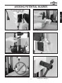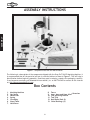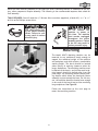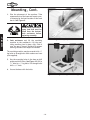
1
MODEL W1671
Mortising Machine
INSTRUCTION MANUAL
Phone: 1-360-734-3482 • On-Line Technical Support: [email protected]
COPYRIGHT © 2002 BY WOODSTOCK INTERNATIONAL, INC. REVISED JANUARY, 2012 (TR)
WARNING: NO PORTION OF THIS MANUAL MAY BE REPRODUCED IN ANY SHAPE OR FORM WITHOUT
THE WRITTEN APPROVAL OF WOODSTOCK INTERNATIONAL, INC.
Printed in China
�����������������������������������������������������������������������
��������������������������������������������������������������
����������������������������������������������������������������������
��������������������������������������������������������������������
������������������������
�����������������������������������������������������������������������
������������������������������������������������������������������������
�������������������������������������������������������������������
�����������������������������������������������������������������
����������������������������������������������������������������������
�����������������������������������������������
����������������������������������������������������������������
��������������������������������������������������������������������
�������
��������������������������������������������������������������������
�����������������������������������������������������������������������
����������������������������������������������������������������������
�������������������������������������
�� ����������������������������
�� ������������������������������������������������������������������
�� ����������������������������������������������������
������������������������������������������������������������������
������������������������������������������������������������������
��������������������������������������������������������������������
���������������������������������������������������������������������
��������������������������
1.
7.
PARTS
USE THE QUICK GUIDE PAGE LABELS TO SEARCH OUT INFORMATION FAST!
MAINTENANCE
6.
OPERATIONS
5.
ADJUSTMENTS
4.
ASSEMBLY
3.
SAFETY
2.
PAGE
INTRODUCTION ............................................................................... 2
ABOUT YOUR NEW MORTISING MACHINE ........................................... 2
WOODSTOCK SERVICE AND SUPPORT ................................................ 2
WARRANTY, RETURNS AND SPECIFICATIONS ....................................... 3
SAFETY ......................................................................................... 4
STANDARD SAFETY INSTRUCTIONS ................................................. 4-5
MORTISING MACHINE SAFETY ......................................................... 5
ELECTRICAL REQUIREMENTS .......................................................... 6
AVOIDING POTENTIAL INJURIES ...................................................... 7
ASSEMBLY INSTRUCTIONS .................................................................. 8
BOX CONTENTS .......................................................................... 8
MOUNTING ............................................................................ 9-10
HAND LEVER ............................................................................. 11
GAS SPRING .............................................................................. 12
WORK TABLE ............................................................................ 13
FENCE ..................................................................................... 13
HOLD DOWN ............................................................................. 14
INSTALLING CHISELS ................................................................... 15
ADJUSTMENTS ............................................................................... 16
GAS SPRING LOCATIONS ............................................................... 16
GAS SPRING PLACEMENT .............................................................. 17
PIVOT FEATURE ......................................................................... 18
FENCE ADJUSTMENTS..............................................................18-19
WIDER STOCK ............................................................................ 19
OPERATIONS ................................................................................. 20
TEST RUN ................................................................................ 20
MAKING A MORTISE .................................................................20-21
MAINTENANCE ............................................................................... 22
GENERAL ................................................................................. 22
FENCE AND CHISELS.................................................................... 22
LUBRICATION ............................................................................ 22
CLOSURE ...................................................................................... 23
PARTS BREAKDOWN AND PARTS LISTS .........................................24-25
YOUR NOTES ............................................................................. 26
INTRODUCTION
Table Of Contents
INTRODUCTION
INTRODUCTION
ABOUT YOUR NEW MORTISING MACHINE
This Shop Fox® Mortising Machine has been specially designed by Woodstock International, Inc. to provide
many years of trouble free service. Close attention to detail, ruggedly built parts and a rigid quality
control program assure safe and reliable operation.
The Model W1671 Mortising Machine features a 1⁄2" drill chuck, a quick-setting handle, an adjustable
depth stop and a reliable rack and pinion elevation system. Combined with a 3⁄4 H.P. motor, a safety
switch with removable key and a cord set, the Shop Fox® Mortising Machine will give years of satisfying
use.
Woodstock International, Inc. is committed to customer satisfaction in providing this manual. It is our
intent to make sure all the information necessary for safety, ease of assembly, practical use and durability of this product be included.
If you should have any comments regarding this manual, please feel free to contact us at:
Woodstock International, Inc.
P.O. Box 2309
Bellingham, WA 98227
[email protected]
WOODSTOCK SERVICE AND SUPPORT
We stand behind our machines! In the event that a defect is found, parts are missing or questions arise
about your machine, please contact Woodstock International Service and Support at 1-360-734-3482 or
[email protected]. Our knowledgeable staff will help you troubleshoot problems, send out
parts or arrange warranty returns.
-2-
Woodstock International, Inc. warrants all SHOP FOX® machinery to be free of defects from workmanship and materials for a period of 2 years from the date of original purchase by the original owner. This
warranty does not apply to defects due directly or indirectly to misuse, abuse, negligence or accidents,
lack of maintenance, or to repair or alterations made or specifically authorized by anyone other than
Woodstock International, Inc.
Woodstock International, Inc. will repair or replace, at its expense and at its option, the SHOP FOX®
machine or machine part which in normal use has proven to be defective, provided that the original
owner returns the product prepaid to the SHOP FOX® factory service center or authorized repair facility
designated by our Bellingham, WA office, with proof of their purchase of the product within 2 years,
and provides Woodstock International, Inc. reasonable opportunity to verify the alleged defect through
inspection. If it is determined there is no defect, or that the defect resulted from causes not within the
scope of Woodstock International Inc.'s warranty, then the original owner must bear the cost of storing
and returning the product.
This is Woodstock International, Inc.'s sole written warranty and any and all warranties that may be
implied by law, including any merchantability or fitness, for any particular purpose, are hereby limited
to the duration of this written warranty. We do not warrant that SHOP FOX® machinery complies with the
provisions of any law or acts. In no event shall Woodstock International, Inc.'s liability under this warranty exceed the purchase price paid for the product, and any legal actions brought against Woodstock
International, Inc. shall be tried in the State of Washington, County of Whatcom. We shall in no event
be liable for death, injuries to persons or property or for incidental, contingent, special or consequential
damages arising from the use of our products.
Every effort has been made to ensure that all SHOP FOX® machinery meets high quality and durability
standards. We reserve the right to change specifications at any time because of our commitment to
continuously improve the quality of our products.
Machine Specifications
Capacities:
Head Travel ..................................................................................................... 9''
Chuck ............................................................................................................1⁄2''
Chisel Shank ........................................................................................... 5⁄8" or 3⁄4''
Hold Down Height ............................................................................ 41⁄2'', 61⁄2'', 81⁄2''
Motor:
Type ...........................................................................TEFC Capacitor Start Induction
Horsepower ............................................................................................... 3⁄4 H.P.
Phase ⁄ Cycle ............................................................................ Single Phase ⁄ 60 Hz
Voltage ........................................................................................................110V
Amps............................................................................................................... 8
R.P.M. ......................................................................................................... 3450
Power Transfer ..................................................................................... Direct Drive
Bearings .................................................... Sealed & Permanently Lubricated Ball Bearing
Switch .....................................................................................Paddle Safety Switch
-3-
INTRODUCTION
WARRANTY, RETURNS AND SPECIFICATIONS
SAFETY
SAFETY FIRST!
READ MANUAL BEFORE OPERATING MACHINE
FAILURE TO FOLLOW INSTRUCTIONS BELOW WILL
RESULT IN PERSONAL INJURY
Indicates an imminently hazardous situation which, if not avoided, WILL
result in death or serious injury.
Indicates a potentially hazardous situation which, if not avoided, COULD
result in death or serious injury.
Indicates a potentially hazardous situation which, if not avoided, MAY
result in minor or moderate injury. It may also be used to alert against
unsafe practices.
NOTICE
This symbol is used to alert the user to useful information about proper
operation of the equipment.
1. Thoroughly read the instruction manual before operating your machine. Learn the applications,
limitations and potential hazards of this machine. Keep manual in a safe, convenient place for future
reference.
2. Keep work area clean and well lighted. Clutter and inadequate lighting invite potential hazards.
3. Ground all tools. If a machine is equipped with a three-prong plug, it must be plugged into a threehole electrical outlet or grounded extension cord. If using an adapter to aid in accommodating a
two-hole receptacle, ground using a screw to a known ground.
4. Wear eye protection at all times. Use safety glasses with side shields or safety goggles, meeting the
national safety standards, while operating this machine.
5. Avoid dangerous environments. Do not operate this machine in wet or open flame environments.
Airborne dust particles could cause an explosion and severe fire hazard.
6. Ensure all guards are securely in place and in working condition.
7. Make sure switch is in the “OFF” position before connecting power to machine.
8. Keep work area clean; free of clutter, grease, etc.
9. Keep children and visitors away. All visitors should be kept a safe distance away while operating
unit.
10. Childproof workshop with padlocks, master switches or by removing starter keys.
11. Disconnect machine when cleaning, adjusting or servicing.
12. Do not force tool. The machine will do a safer and better job at the rate for which it was
designed.
13. Use correct tool. Do not force machine or attachment to do a job for which it was not designed.
-4-
14. Wear proper apparel. Do not wear loose clothing, neck ties, gloves, jewelry, etc.
15. Remove adjusting keys and wrenches. Before turning the machine on, make it a habit to check that
all adjusting keys and wrenches have been removed.
17. Keep proper footing and balance at all times.
18. Do not leave machine unattended; wait until it comes to a complete stop before leaving the
area.
19. Perform machine maintenance and care. Follow lubrication and accessory attachment instructions
in the manual.
20. Keep machine away from open flame. Operating machines near pilot lights and/or open flames
creates a high risk if dust is dispersed in the area. Dust particles and an ignition source may cause
an explosion. Do not operate the machine in high risk areas, including but not limited to, those mentioned above.
Additional Safety Instructions For
Mortising Machines
1.
Do not use Mortising Machine for anything except mortising in wood. Materials such as metals,
plastics and glass can damage the machine resulting in personal injury.
2.
Do not adjust machine or workpiece while running. Wait for spindle to come to a complete stop
and unplug the machine before continuing.
3.
Do not place your hands near the chisel while spindle is in motion.
4.
Always wear a respirator and safety glasses while operating mortising machine. Dust and chips
are created when mortising. Some debris will be ejected becoming eye and breathing hazards.
5.
Never use tools that are in poor condition. Inspect Mortising Machine for free motion of the
head casting, loose drill bit/chisel housing, loose nuts/bolts and unusual sounds before connecting
machine to power and operating. Correct any problems before use.
6.
Chisels are sharp! Always use caution when handling, especially when installing or removing.
7.
Never allow hands to be under installed chisel at any time.
8.
Chisels may become hot during operation. Allow chisels to cool before handling.
9.
If at any time you are experiencing difficulties performing the intended operation, stop using
the machine! Then contact our service department or ask a qualified expert how the operation
should be performed.
10. Always set depth stop to bottom and lock before adjusting quick-setting handle or changing air
spring locations.
11. Habits – good and bad – are hard to break. Develop good habits in your shop and safety will become
second-nature to you.
-5-
SAFETY
16. Use proper extension cord. When using an extension cord, make sure it is in good condition. When
extension cord is 100' and less in length, use those that are rated Hard Service (grade S) or better,
and that have a conductor size of 16 A.W.G. A drop in line voltage, loss of power and overheating
can result when using an undersized cord. The extension cord should have a ground wire and ground
plug pin, as well.
ELECTRICAL REQUIREMENTS
SAFETY
110V Operation
This equipment must be grounded. Verify
that any existing electrical outlet and circuit
you intend to plug into is actually grounded.
If it is not, it will be necessary to run a
separate 12 A.W.G. copper grounding wire
from the outlet to a known ground. Under no
circumstances should the grounding pin from
any three-pronged plug be removed. Serious
injury may occur.
The Shop Fox® W1671 Mortising Machine can
only be operated at 110 volts. The motor supplied with your new Mortising Machine is rated
at 3⁄4 H.P. and will draw approximately 8 amps.
When choosing an outlet for this machine, consider using one with a 10 amp circuit breaker or
fuse. Keep in mind that a circuit being used by
other machines or tools at the same time will
add to the electrical load being applied by the
Mortising Machine. Add up the load ratings of all
machines on the circuit. If this number exceeds
the rating of the circuit breaker or fuse, use a
different outlet.
Extension Cords
When it is necessary to use an extension cord,
use the following guidelines:
•Use cords rated for Hard Service
•Never exceed a length of 100 feet
•Use cords with 14 ga. wire or bigger
•Insure cord has a ground wire and pin
•Do not use cords in need of repair
Grounding
This machine must be grounded! See Figure 1.
The electrical cord for the Model W1671 is supplied with a 3 prong plug. If your outlet does not
accommodate a ground pin, have it replaced by
a qualified electrician or have an appropriate
adapter installed and grounded properly. An
adapter with a grounding wire does not guarantee the machine will be grounded. The ground
source must be verified.
Figure 1. Typical 110V 3-prong plug and outlet.
-6-
AVOIDING POTENTIAL INJURIES
SAFETY
Figure 2. Unplug before changing chisels.
Figure 3. Always clamp workpiece.
Fig. 4. Secure depth stop before removing gas spring.
Figure 5. Remove safety key when not in use.
Figure 6. Never place hands under chisel.
-7-
Fig. 6A. Secure depth stop before adjusting quick-set
handle above. See Fig. 4.
ASSEMBLY
ASSEMBLY INSTRUCTIONS
Figure 7. Components laid out for identification.
The following is a description of the components shipped with the Shop Fox® W1671 Mortising Machine. It
is recommended that all the parts be laid out in a similar fashion to those in Figure 7. This will help in
identification before beginning assembly. Should any part be missing, examine the packaging carefully.
If any key parts are missing call Woodstock International, Inc. at 360-734-3482 or contact on the internet
at: [email protected].
Box Contents
1.
2.
3.
4.
5.
6.
7.
8.
9.
10.
11.
12.
13.
Mortising Machine
Gas Spring
Hand Lever
Spring
Chuck Key
Wood Table
Hold Down
-8-
Fence
4mm, 6mm and 8mm Allen® Wrenches
Fine Adjusting Bracket
Tool Tray
Hold Down Rods (3)
Chisel Bushings (2)
While the main mortising assembly of the Shop Fox® W1671 Mortising Machine is assembled at the factory, other components require assembly. The following is the recommended sequence best suited for
final assembly.
TOOLS REQUIRED: You will need the 4, 5 & 6mm Allen® wrenches (supplied), a hand drill, a 1⁄4" or 5⁄16"
drill bit and a Phillips® screw driver.
Wear safety glasses during the entire assembly
process. Failure to comply may result in serious
personal injury.
Mounting
The Model W1671 Mortising Machine can be
mounted to any workbench sturdy enough to
support the combined weight of the machine
and workpiece and which allows a comfortable
working height. The bench should be located
where plenty of working clearance exists for
larger workpieces. The mortising machine must
be bolted to the bench, and to help avoid a tipping hazard, should be bolted away from the
front edge. The mortising machine has a pivoting feature which allows the head and column
assembly to pivot around the base. For this reason, the machine should be located near enough
to one end of the bench top to allow mortising
long workpieces. See Figure 8.
Figure 8. Machine positioned near edge of bench.
Follow the instructions on the next page to
mount the mortising machine.
-9-
ASSEMBLY
Do not connect the
machine to power at
this time. The machine
must remain unplugged
throughout the entire
assembly process. Failure
to do this may result in
serious personal injury.
Mounting, Cont.
1. Plan the placement of the mortiser. Take
measurements of the base and layout a pencil drawing for the best location on the work
bench. See Figure 9.
ASSEMBLY
The Mortiser represents a
heavy load that must be
lifted from the bottom.
Seek assistance before
beginning assembly.
Figure 9. Layout penciled in.
2. Seek assistance and lift the mortising
machine to the workbench. Lift the mortising machine from its base, only. Slide it
over the pencil layout. Recheck for proper
working clearance and adjust as needed.
The mortising machine may be secured with 5⁄16"
lag bolts or through bolts with washers and nuts
(not supplied).
3. Use the mounting holes in the base as drill
guides and drill holes. See Figure 10. Drill a
1
⁄4" hole for 5⁄16" lag bolts. For through bolts
drill a 5⁄16" hole.
4. Secure the base with the bolts.
Figure 10. Using mounting holes as drill guides.
-10-
Hand Lever
Hub
Clutch
Position depth stop to
touch table and secure
with lock knob before
attaching hand lever.
The head may drop suddenly causing injury.
Spring
Shouldered
Bolt
Figure 11. Assembly break down.
1. Locate the shouldered bolt, clutch and
small spring.
2. Insert the spring into the clutch and place
the clutch on the hub.
3. Secure the spring and clutch using the
shouldered bolt. Insert the bolt and tighten. Refer to Figure 11 for the layout of the
parts.
4. Loosen the setscrew securing the collar
closest to the end of the hand lever and
remove the collar.
5. Insert the end of the hand lever into the
smaller slot in the clutch. Slide the collar
back onto the end of the hand lever and
secure by tightening the setscrew. The
lower collar should be set below the clutch
by 1" to allow working clearances when the
lever is swung out for indexing.
Figure 11A. Secure collar onto hand lever.
The hand lever can be adjusted for height by
moving both of the collars up or down. Adjust
these collars to accommodate the most comfortable height for operation.
-11-
ASSEMBLY
Attaching the hand lever requires the use of the
4 and 5mm Allen® wrenches supplied.
Gas Spring
ASSEMBLY
The gas spring can be secured to 3 different
locations along the side or back of the left column. Each location offers a different range of
motion for the mortising head. In the instructions below, we will cover only the side location. Further explanation will follow in the
Adjustments section.
Position depth stop to
touch table and secure
with lock knob before
indexing the hand lever.
The head may drop suddenly, causing injury.
Figure 12. Indexing handle by swinging out.
1. Adjust the depth stop lever until it touches
the table surface.
2. Lift the head using the hand lever. If necessary, index the lever (Figure 12) to make
multiple turns of the hub so the head moves
to its highest elevation. Be sure to position
the depth stop rod so that it touches the
base of the machine and lock it in place
before indexing the handle. This ensures
the weight of the head casting is supported while adjustments are made.
3. The gas spring ends snap into place over
the ball-end junction. It may be necessary
to compress the gas spring slightly to align
sockets in gas springs with ball-end junction. See Figure 13.
Figure 13. Compressing gas spring to assemble.
-12-
Work Table
1. Secure the wooden work table with the 2
Phillips® head screws provided. See Figure
14.
Fence
1. The fence comes with a micro-adjustable
stop attached to the fence support rod,
which retains a spring. Loosen the setscrew
with the 4mm Allen® provided and remove
the stop but not the spring.
2. Slide the support rod into the mounting
block located between the columns. See
Figure 15.
Figure 15. Slide fence support through block.
3. Replace the micro-adjustable stop and
secure with the setscrew. See Figure 16.
Figure 16. Micro-adjustable stop in position.
-13-
ASSEMBLY
Figure 14. Work table secured with screws.
Hold Down
The hold down acts as a clamp, holding the
workpiece to the table surface. This helps to
keep the workpiece from raising when extracting the chisel after a cut is made. The hold
down must be used.
ASSEMBLY
1. Support the head with the hand lever
and unlock the depth stop lock knob.
Allow depth stop rod to touch the base
surface and secure the rod in place.
2. The hold down support rod has a flat
portion along its length. Place the completely round portion into the fence. Do
not tighten the screw in the fence at
this time.
Figure 17. Bracket in the lowest position.
3. The hold down bracket may be placed
on the support rod in two positions.
If placed on the support rod as in
Figure 17, the bracket will hold down a
workpiece slightly taller than the fence.
When placed in the position shown in
Figure 18, the bracket will hold down
a workpiece that measures 3⁄8" less than
the height of the support rod.
There are 3 hold down support rods supplied
with the mortising machine. The length of
the support rod used will be determined by
the height of the workpiece. More information about using the hold down is detailed in
the section titled Adjustments.
Figure 18. Bracket in the highest position.
-14-
Installing Chisels
Always unplug the mortising machine before
changing chisels. Failure
to do this may result in
serious personal injury.
Select the size needed for your project and follow the instructions below.
1. Support the head with the hand lever
and unlock the depth stop lock knob.
Allow depth stop rod to touch the base
surface and secure the rod in place.
2. Remove the hold down bracket from the
support rod and move the fence to the
back edge of the work table.
4. Slide the end of the chisel housing
into the bushing located just under the
chuck. Make sure the opening in the
chisel face is away from the operator.
WRONG
5. Tighten the cap screw to the side of
the chisel mount with the 5mm Allen®
wrench provided.
Figure 19. Drill bit must extend beyond chisel.
6. Tighten the drill bit into the drill chuck
with the chuck key provided. Make sure
the drilling end of the drill bit is positioned just outside the end of the chisel
housing. See Figure 19.
7. Place a straight, tall board against
fence and adjust the fence until
board touches the back edge of
chisel. Tighten the lock handle for
fence.
the
the
the
the
8. Loosen the cap screw holding the chisel
housing and rotate the chisel until the
back surface is parallel-with the board.
See Figure 20. Tighten the cap screw.
Figure 20. Back edge of chisel parallel with fence.
-15-
ASSEMBLY
3. Protect your hands. Use gloves or wrap
a shop towel around the sharp end of
the chisel.
ADJUSTMENTS
Gas Spring Locations
The gas spring can be positioned in 1 of 3 locations to allow clearance for different board
thicknesses or to mortise a board on edge. To
determine which setting to use, look at the
chart in Figure 21 and find the board thickness
that most closely fits your workpiece. Note the
number that corresponds with that board. This
will be the position number shown in Figure 22.
Follow the instructions on the following page to
place the gas spring in the new location.
8½”
2½”
4½”
ADJUSTMENTS
Figure 21. Maximum board thicknesses.
1
2
3
Figure 22. Gas spring positions.
-16-
Gas Spring Placement
Swinging the handle out will cause the head
casting to fall when the gas spring is removed.
The gas spring supports the weight of the head
casting and the hand lever regulates its height.
However, if the handle is pulled while the gas
spring is removed the head will drop suddenly.
Please read the Caution to the left.
Upon determining which location the gas spring
is to be placed, follow the instructions below.
Figure 23. Snapping gas spring into place.
1. Support the head with the hand lever and
unlock the depth stop lock knob. Allow the
depth stop rod to touch the base surface
and secure the depth stop rod in place.
2. The gas spring ends will snap off of the ball
end junctions. Remove the gas spring.
3. Snap the gas spring into place over the
desired ball-end junction locations. See
Figure 23. It may be necessary to compress
gas spring slightly or to further lift or lower
the head using the handle to align the sockets in the gas springs with the ball-end junctions.
Never make adjustments
to the head when a chisel
is installed into the mortising machine. Serious
injury will occur if the
head drops suddenly.
-17-
ADJUSTMENTS
Position depth stop rod
to touch table and secure
with lock knob before
removing the gas spring.
The head may drop suddenly, causing injury.
Pivot Feature
The head and column assembly can be adjusted
for mortising off of the base. This will allow the
mortising machine to accommodate a larger
workpiece than those previously listed. To
change the position of the head and column
assembly:
1. Support the head with the hand lever and
unlock the depth stop lock knob. Allow the
depth stop rod to touch the base surface
and secure the rod in place.
2. Loosen the two hex nuts in the pivoting
base.
Figure 24. Workpiece clamped to edge of table.
3. Rotate the assembly to the desired angle.
ADJUSTMENTS
4. Tighten the hex nuts.
5. The worktable should be removed before
operating the machine.
Secure the workpiece with clamps before
using the machine. See Figure 24.
Fence Adjustments
The fence is supplied with a fine adjusting
assembly, a spring and a collar. These enable
centering the chisel to the workpiece quickly
and with accuracy.
WRONG
Figure 25. Drill bit must extend beyond chisel.
1. Support the head with the hand lever and
unlock the depth stop lock knob. Allow
depth the stop rod to touch the base surface
and secure the rod in place.
2. Loosen the locking lever for the fence.
3. Use a pencil to mark the mortise on the
workpiece.
4. Install the mortising chisel with the drill bit.
The drill bit must be positioned so the end
extends beyond the chisel body for proper
chip clearance. See Figure 25.
Figure 26. Setting micro-adjusting block.
-18-
5. Place the workpiece against the fence and
position the fence so the chisel is near the
penciled in marks. Lock the fence.
6. Loosen the setscrew holding the micro adjustment block on the fence mounting rod and
move the block until the screw fits into the
back of the support block. See Figure 26 on
the previous page.
7. Unlock the fence and rotate the micro adjustable knob until the chisel lines up withthe
penciled in lines as in Figure 27.
Figure 27. Aligning chisel to marked workpiece.
Wider Stock
1. Remove the mortising chisel and drill bit.
3. Carefully lift the head stock assembly until
pivot base clears the locking studs. Lay the
assembly on its side on the workbench.
4. Remove the 3 cap screws holding the support block to the pivot base as in Figure
28.
Note that the support block is in position A (in
Figure 29) when the block is closest to the fence
and position B when the block is furthest from
the fence.
Figure 28. Repositioning the support block.
5. Reposition the support block to position B.
6. Reattach the support block with the 3 cap
screws.
Reattach the head casting assembly and follow
the instructions above for fence and workpiece
setup.
Figure 29. Support block locations.
-19-
ADJUSTMENTS
2. Loosen and remove the 2 hex nuts on the
top of the pivot base.
OPERATIONS
Test Run
Once assembly is complete and adjustments are
done to your satisfaction, you are ready to test
run the machine.
OPERATIONS
Always wear safety glasses when operating this
Mortising Machine. Failure
to comply may result in
serious personal injury.
Make sure the starting switch is off. The paddle
is down for off. Make sure all the fasteners and
lock handles are tight. Plug in the power cord.
Pull the START paddle. Make sure that your finger is poised over the paddle, Figure 30, just in
case there is a problem. The Mortising Machine
should run smoothly, with little or no vibration
or rubbing noises. Normally, there is some noise
generated by the drill bit turning inside the
chisel. If noise is excessive, it is likely the drill
bit needs to be lowered a little inside the chisel.
Any strange or unnatural noises require you to
stop the machine, wait for it to stop moving,
unplug the machine, investigate and correct the
problem before further operation.
Figure 30. Hand poised over stop paddle.
DO NOT attempt to
investigate or adjust
the machine while it is
running. Wait until the
machine is turned off,
unplugged and all working parts have come to a
stop before proceeding!
If the source of an unusual noise or vibration is
not readily apparent, please contact our service
department for help at 1-360-734-3482 or by
email at: [email protected].
Making A Mortise
1. Support the head with the hand lever and
unlock the depth stop lock knob. Allow the
depth stop rod to touch the base surface
and secure the rod in place.
2. Check the set up of the mortising machine
to ensure head height and range of motion
is sufficient. Also, check fasteners and
locks.
3. Adjust the depth stop rod to correct depth
for producing blind mortises. In Figure 31,
Figure 31. Setting the depth stop to 27⁄8".
-20-
the head is lowered so the chisel rests on the
workpiece. The depth stop rod is adjusted
using a measuring tape, to the desired
depth. Figure 32 shows the chisel being
lowered until the chisel is even with a depth
line on the workpiece. The fence is adjusted
before and after the depth stop is locked.
4. Carefully mark the outline of the mortise
on the workpiece. Align the fence and
workpiece so the chisel aligns with the markings. See section on Fence Adjustments. A
sacrificial board should be used under the
workpiece whenever through-holes are produced to minimize tear out and protect the
work table.
Figure 32. Use penciled line to gauge depth.
5. Test the positioning setup with a piece of
scrap lumber of the same dimensions as the
workpiece. Position the hold down on top of
the workpiece and secure with cap screw.
Do Not mortise without a hold down.
The chisel will become
hot during operation. Use
gloves or wait until chisel
has cooled before removing. Serious personal injury may occur.
5
2
6
3
7
7. Lower the head by pulling the hand lever
down with your right hand. Be sure not to
feed the chisel too fast or too slow. Feeding
too fast can cause the drill bit to clog with
chips causing the motor to slow down and
overheat. Feeding too slow may cause excessive heat, ruining the chisel. However, it is
normal for some discoloring of the chisel to
occur due to heat generated during use.
4
8. When desired depth is achieved, move the
hand lever back to its original position. The
workpiece should remain in place as this is
done.
9. Check the placement of hole on the test piece
and adjust the fence if necessary. Continue
with the actual workpiece when the desired
accuracy of placement is achieved.
Figure 33. Sequence of cuts.
10. When making rectangular mortises, we recommend you follow the sequence of cuts
shown in Figure 33. Please note that cuts 5,
6 and 7 will only use a portion of the chisel
and so the chisel should be positioned over
the center of each space.
-21-
OPERATIONS
1
6. Turn the power ON.
MAINTENANCE
General
Fence And Chisels
The cast iron fence and steel chisels/bits can be
kept rust-free with regular applications of products like Boeshield® T-9. For long term storage
you may want to consider products like Kleen
Bore's Rust Guardit™.
Disconnect power to the
machine when performing any maintenance or
repairs. Failure to do this
may result in serious personal injury.
Lubrication
Since all bearings are sealed and permanently
lubricated, simply leave them alone until they
need to be replaced. Do not lubricate them.
Regular periodic maintenance on your Model
W1671 Mortising Machine will ensure its optimum performance. Make a habit of inspecting
the machine each time you use it. Check for the
following conditions and repair or replace when
necessary.
Loose mounting bolts.
2.
Worn switch.
3.
Worn or damaged cords and plugs.
4.
Any other condition that could hamper the
safe operation of this machine.
Your goal is to achieve adequate lubrication.
Too much lubrication will attract dirt and sawdust. Various parts of your machine could lose
their freedom of movement as a result.
Lubricating Drill Bits
The drill bits for mortising chisels operate under
extreme conditions. A small amount of bees
wax applied to the drill bit can aid in reducing
heat and expelling chips. It is important that a
small amount is used and none is applied to the
chisel. Bees wax coming into contact with the
finished surfaces will impede adhesion of glues
and finishes.
MAINTENANCE
1.
For other items on this machine, such as the
gear, base and columns, an occasional application of light machine oil is all that is necessary.
Before applying lubricant, clean off sawdust and
wood chips.
-22-
CLOSURE
The following pages contain general machine
parts diagrams/lists and warranty/return information for your Shop Fox® Model W1671 Mortising
Machine.
We recommend you keep this manual for
complete information regarding Woodstock
International, Inc.’s warranty and return policy.
If you need additional technical information
relating to this machine, or if you need general
assistance or replacement parts, please contact
the Service Department at 360-734-3482 or [email protected] on the internet.
If you need parts or help in assembling your
machine, or if you need operational information, we encourage you to call our service
department. Our trained service technicians will
be glad to help you.
Additional information sources are necessary to
realize the full potential of this machine. Trade
journals, woodworking magazines, and your
local library are good places to start.
The Model W1671 was specifically designed for
If you have comments dealing specifically with
this manual, please write to us using the address
in the General Information. The specifications,
drawings, and photographs illustrated in this
manual represent the Model W1671 as supplied
when the manual was prepared. However, due
to Woodstock International, Inc.’s policy of
continuous improvement, changes may be made
at any time with no obligation on the part of
Woodstock International, Inc. Whenever possible, though, we send manual updates to all
owners of a particular tool or machine. Should
you receive one, add the new information to this
manual and keep it for reference.
As with all power tools, there is danger
associated with the Model W1671 Mortising
Machine. Use the tool with respect and caution to lessen the possibility of mechanical
damage or operator injury. If normal safety
precautions are overlooked or ignored, injury to the operator or others in the area is
likely.
mortising operations. DO NOT MODIFY AND/OR
USE THIS MORTISING MACHINE FOR ANY OTHER
PURPOSE. Modifications or improper use of this
tool will void the warranty. If you are confused
about any aspect of this machine, DO NOT use it
until all your questions have been answered.
We have included some important safety measures that are essential to this machine’s operation. While most safety measures are generally
universal, we remind you that each workshop is
different and safety rules should be considered
as they apply to your specific situation.
-23-
MAINTENANCE
Keep your shop “Child
Safe.” Always remove the
switch safety key when
Mortising Machine is not
in use. Serious injury may
occur.
70
1B
29B
62A
62B
71
12
14
13
15
3
11
2B
81
8
82
9
35
87
17
88
89
16
4
25
6
85
84
24
7B
5
29A-1
58A
58B
21
58C
18
69
32
56-1
57B
36
56
33
37
37
39
38
53
57A
63
42
50
51
23
44
46
64
55
37
22
19 20
34
52C
52B
52A
45
40
49
48
26
65
60
7A
83
41
PARTS
23
59
86
54
29A
10
67
47
68
-24-
43
27
28
REF PART #
DESCRIPTION
REF PART #
DESCRIPTION
01B X1671001B
02B X1671002B
3
X1671003
4
X1671004
5
X1671005
6
XPSB14M
07A X1671007A
07B X1671007B
8
X1671008
9
X1671009
10
X1671010
11
XPW04M
12
XPB32M
13
X1671013
14
XPS14M
15
XPW03M
16
X1671016
17
XPFH02M
18
X1671018
19
X1671019
20
XPS09M
21
X1671021
22
XPS02M
23
XPRP05M
24
X1671024
25
X1671025
26
X1671026
27
X1671027
28V2 X1671028V2
29A X1671029A
29A-1 X1671029A-1
29B X1671029B
32
X1671032
33
X1671033
34
X1671034
35
X1671035
36
X1671036
37
XPSS16M
38
X1671038
39
X1671039
40
X1671040
41
X1671041
42
XPN25M
43
XPB32M
MOTOR
CHUCK JT MOUNT
CHUCK KEY
HEAD CASTING
LABEL
CAP SCREW M8-1.25 X 20
5⁄8" BUSHING
�" BUSHING
DEPTH STOP ROD
GUIDE BUSHING
STOP PLATE
FLAT WASHER 10MM
HEX BOLT M10-1.5 X 25
HOLDER
PHLP HD SCR M6-1 X 12
FLAT WASHER 6MM
SPECIAL WASHER 6MM
FLAT HD SCR M6-1 X 12
COVER
HINGE
PHLP HD SCR 5-.8 X 10
COVER PLATE
PHLP HD SCR M4-.7 X 12
ROLL PIN 5 X 30
GEAR
GEAR SHAFT
CLUTCH COLLAR
SPRING
SHOULDER BOLT M10-1.5 X 28 V2.11.11
HANDLE
STOP COLLAR
HAND GRIP
COLUMN
RACK COLUMN
LOCK KNOB M8-1.25 X 35
LOCK KNOB M8-1.25 X 20
KNOB M8-1.25 X 56
SETSCREW M8-1.25 X 10
STOP BRACKET
GUIDE BRACKET
ROTARY TABLE TOP
STUD
HEX NUT M14-2
HEX BOLT M10-1.5 X 25
44
45
46
47
48
49
50
51
52A
52B
52C
53
54
55
56
56-1
57A
57B
58A
58B
58C
59
60
62A
62B
63
64
65
67
68
69
70
71
80
81
82
83
84
85
86
87
88
89
FLAT WASHER 9⁄16"
CAP SCREW M10-1.5 X 25
LOCK WASHER 8MM
TABLE
FLAT HD SCR M8-1.25 X 25
BASE
SPRING
COLLAR
ROD
ROD
ROD
CAP SCREW M8-1.25 X 20
HOLD DOWN
FENCE
GAS SPRING
GAS SPRING END
LOWER JUNCTION SCREW
UPPER JUNCTION SCREW
ALLEN WRENCH 4MM
ALLEN WRENCH 5MM
ALLEN WRENCH 6MM
CAP SCREW M6-1 X 25
CAP SCREW M8-1.25 X 25
SWITCH
SWITCH KEY
HEX NUT M6-1
FENCE SUPPORT ROD
CLUTCH
FLAT WASHER 10MM
LOCK WASHER 10MM
HAND/CHISEL WARNING
SAFETY GLASSES WARNING
DEPTH STOP WARNING
COLLAR
FLAT HD SCR M6-1 X 20
O-RING 32 X 3
WOOD SCREW M3 X 12
LID
CAPACITOR 30 MFD
MOTOR FAN
FAN COVER
FLAT WASHER 5MM
PHLP HD SCR M5-.8 X 8MM
PARTS
-25-
XPW16
XPSB13M
XPLW04M
X1671047
XPFH21M
X1671049
X1671050
X1671051
X1671052A
X1671052B
X1671052C
XPSB14M
X1671054
X1671055
X1671056
X1671056-1
X1671057A
X1671057B
XPAW04M
XPAW05M
X1671058C
XPSB06M
XPSB31M
X1671062A
X1671062B
XPN01M
X1671064
X1671065
XPW04M
XPLW06M
X1671069
X1671070
X1671071
X1671080
XPFH06M
X1671082
X1671083
X1671084
X1671085
X1671086
X1671087
XPW02M
XPS05M
Your Notes:
-26-
WARRANTY CARD
Name ___________________________________________________________________________________________
Street __________________________________________________________________________________________
City ____________________________________________________________________State________Zip_________
Phone Number_______________________E-Mail_________________________________FAX___________________
MODEL # ____________________________________________ SERIAL #____________________________________
The following information is given on a voluntary basis and is strictly confidential.
1.
Where did you purchase your Shop Fox® machine?
__________________________________________________________
2.
How did you first learn about us?
___Advertisement
___Mail order Catalog
___World Wide Web Site
9.
10.
___Air Compressor
___Panel Saw
___Band Saw
___Planer
___Mortising Machine
___Power Feeder
___Drum Sander
___Radial Arm Saw
___Dust Collector
___Shaper
___Horizontal Boring Machine
___Spindle Sander
___Jointer
___Table Saw
___Lathe
___Vacuum Veneer Press
___Mortiser
___Wide Belt Sander
___Other__________________________________________________
___Friend
___Local Store
___Other__________________________________________________
CUT ALONG DOTTED LINE
3.
Which of the following magazines do you subscribe to.
___American Woodworker
___Today’s Homeowner
___Cabinetmaker
___WOOD
___Family Handyman
___Wooden Boat
___Fine Homebuilding
___Woodshop News
___Fine Woodworking
___Woodsmith
___Home Handyman
___Woodwork
___Journal of Light Construction
___Woodworker
___Old House Journal
___Woodworker’s Journal
___Popular Mechanics
___Workbench
___Popular Science
___American How-To
___Popular Woodworking
___Other__________________________________________________
4.
11.
12.
Which of the following woodworking/remodeling shows do you watch?
What is your annual household income?
___$20,000-$29,999
___$30,000-$39,999
___$40,000-$49,999
___$50,000-$59,999
6.
7.
8.
13.
___$60,000-$69,999
___$70,000-$79,999
___$80,000-$89,999
___$90,000 +
__________________________________________________________
__________________________________________________________
___50-59
___60-69
___70 +
___8 - 20 Years
___20+ Years
14.
What new accessories would you like Woodstock International to carry?
_________________________________________________________
_________________________________________________________
15.
Do you think your purchase represents good value?
___Yes
16.
How would you rank your woodworking skills?
___Simple
___Intermediate
What machines/supplies would you like to see?
__________________________________________________________
__________________________________________________________
How long have you been a woodworker?
___0 - 2 Years
___2 - 8 Years
Which portable/hand held power tools do you own? Check all that
apply.
___Belt Sander
___Orbital Sander
___Biscuit Joiner
___Palm Sander
___Circular Saw
___Portable Planer
___Detail Sander
___Saber Saw
___Drill/Driver
___Reciprocating Saw
___Miter Saw
___Router
___Other__________________________________________________
What is your age group?
___20-29
___30-39
___40-49
Which benchtop tools do you own? Check all that apply.
___1" x 42" Belt Sander
___6" - 8" Grinder
___5" - 8" Drill Press
___Mini Lathe
___8" Table Saw
___10" - 12" Thickness Planer
___8" - 10" Bandsaw
___Scroll Saw
___Disc/Belt Sander
___Spindle/Belt Sander
___Mini Jointer
___Other__________________________________________________
___Backyard America
___The New Yankee Workshop
___Home Time
___This Old House
___The American Woodworker
___Woodwright’s Shop
___Other__________________________________________________
5.
How many Shop Fox® machines do you own? _____________
What stationary woodworking tools do you own? Check all that apply.
___Advanced
___Master Craftsman
Would you recommend Shop Fox® products to a friend?
___Yes
17.
___No
___No
Comments:________________________________________________
__________________________________________________________
FOLD ALONG DOTTED LINE
Place
Stamp
Here
WOODSTOCK INTERNATIONAL, INC.
P.O. BOX 2309
BELLINGHAM, WA 98227-2309
FOLD ALONG DOTTED LINE
TAPE ALONG EDGES--PLEASE DO NOT STAPLE
High Quality Machines and Tools
Woodstock International, Inc. carries thousands of products designed
to meet the needs of today's woodworkers and metalworkers.
Ask your dealer about these fine products: