1
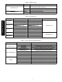
48/50HC04---28
48/50LC04---06
Single ---Package Rooftop Units
with ComfortLink Controls
Economizer Controller (ECB) Accessory
Installation Instructions
PART NUMBERS: CRSRTECB001A00 AND CRMRTECB001A00
TABLE OF CONTENTS
PAGE
SAFETY CONSIDERATIONS . . . . . . . . . . . . . . . . . . . . . . . . . . 1
GENERAL . . . . . . . . . . . . . . . . . . . . . . . . . . . . . . . . . . . . . . . . . 1
ACCESSORIES . . . . . . . . . . . . . . . . . . . . . . . . . . . . . . . . . . . . . 1
INSTALLATION . . . . . . . . . . . . . . . . . . . . . . . . . . . . . . . . . . . . 3
CRSRTECB001A00 with Vertical Economizer
48/50LC04--06 and 48/50HC04--14 Units . . . . . . . . . . . . . . . . 3
CRSRTECB001A00 with Horizontal Economizer
48/50LC04--06 and 48/50HC04--14 Units . . . . . . . . . . . . . . . . 3
CRMRTECB001A00 -- 48/50HC17--28 Units . . . . . . . . . . . . . 4
CONFIGURING THE COMFORTLINK CONTROL . . . . . . . . 5
TROUBLESHOOTING . . . . . . . . . . . . . . . . . . . . . . . . . . . . . . . 5
SAFETY CONSIDERATIONS
Improper installation, adjustment, alteration, service, maintenance,
or use can cause explosion, fire, electrical shock, or other
conditions which may cause personal injury or property damage.
Consult a qualified installer, service agency, or your distributor or
branch for information or assistance. The qualified installer or
agency must use factory--authorized kits or accessories when
modifying this product. Refer to the individual instructions
packaged with kits or accessories when installing.
Follow all safety codes. Wear safety glasses and work gloves. Use
quenching cloth for brazing operations. Have fire extinguisher
available. Read these instructions thoroughly and follow all
warnings or cautions attached to the unit. Consult local building
codes and National Electrical Code (NEC) for special
requirements.
.
Recognize safety information. This is the safety--alert symbol
When you see this symbol on the unit and in instruction manuals,
be alert to the potential for personal injury.
Understand the signal words DANGER, WARNING, CAUTION.
These words are used with the safety--alert symbol. DANGER
identifies the most serious hazards which will result in severe
personal injury or death. WARNING signifies hazards which could
result in personal injury or death. CAUTION is used to identify
unsafe practices which may result in minor personal injury or
product and property damage. NOTE is used to highlight
suggestions which will result in enhanced installation, reliability, or
operation.
Installation and servicing of air-conditioning equipment can be
hazardous due to system pressure and electrical components. Only
trained and qualified service personnel should install, repair, or
service air-conditioning equipment.
IMPORTANT: Do not adjust the damper assembly. The motor
and damper have been pre--set and adjusted for proper operation.
GENERAL
The accessory Economizer Control Board (ECB) package is
required in addition to the Economizer damper accessory kit for
complete economizer operation on ComfortLink Rooftop Units.
Refer to Tables 1 and 2 for specific package contents and usage.
The accessory Economizer Control Board (ECB) package uses
microprocessor based controls in conjunction with the
ComfortLink Main Base Board (MBB) to sequence mechanical
cooling with cool outdoor air (free cooling) to satisfy the cooling
load and minimize energy consumption. Free cooling can be used
alone or in conjunction with mechanical cooling. The control also
provides outdoor air for space ventilation. Minimum damper
position is configurable for this purpose. Additional accessories
may be added for demand controlled ventilation (DCV), indoor air
quality (IAQ) override control, or outdoor air quality (OAQ)
lockout.
The economizer’s ring style outdoor--air temperature (OAT) sensor
is not used; ComfortLink has a probe style OAT factory installed
below the control box. When the outdoor--air temperature is
between two configurable ambient temperatures, the economizer is
allowed to cool. These temperature configurations are the
Economizer High Temperature Lockout (ECL.H) and the
Economizer Low Temperature Lockout (ECL.L). The economizer
will provide cooling when the outdoor temperature is suitable as
defined above by the lockout settings and if there is a cooling
demand. In addition, if an outdoor enthalpy sensor accessory has
been installed, then the enthalpy reading must also be “low” before
economizer cooling can occur.
When free cooling is available, the economizer sequences free
cooling with up to three stages of mechanical cooling to maintain
comfort in the space. When free cooling is not available, the
economizer modulates to an adjustable minimum position to
maintain a supply of fresh air entering the building. Proper
minimum positions must be set per job site requirements.
The barometric relief dampers provide natural building
pressurization control. An optional power exhaust system is
available for jobs requiring greater relief.
ACCESSORIES
The economizer has several field-installed accessory sensors
available to optimize performance. Refer to Table 3 for
field--installed accessories.
Table 1 – Package Contents
PACKAGE NO.
QTY
CRSRTECB001A00
CRMRTECB001A00
CONTENTS
1
Control Board Assembly --- includes Control Board mounted in
sheet metal enclosure with wire harness
4
Self Tap Screws
1
Harness Extension
1
Control Board
5
Screws
Table 2 – Economizer Usage
CRSRTECB / CRMRTECB
UNIT
48/50HC04--06
48/50LC04--06
48/50HC07--12
48/50HC14
48/50HC17--20
48/50HC24--28
DESCRIPTION
ECONOMIZER ACCESSORY
Standard Vertical
CRECOMZR022B00
Standard Horizontal
CRECOMZR026B00
Ultra Low Leak Vertical
CRECOMZR066A00
Standard Vertical
CRECOMZR023B00
Standard Horizontal
CRECOMZR027B00
Ultra Low Leak Vertical
CRECOMZR068A00
Standard Vertical
CRECOMZR063B00
Standard Horizontal
CRECOMZR065B00
Ultra Low Leak Vertical
CRECOMZR070A00
Standard Vert/Horiz
CRECOMZR054B00
Ultra Low Leak Vert/Horiz
CRECOMZR072A00
Standard Vert/Horiz
CRECOMZR055B00
Ultra Low Leak Vert/Horiz
CRECOMZR073A00
CONTROLLER ACCESSORY
CRSRTECB001A00
CRMRTECB001A00
Table 3 – Accessory Sensors Used with Economizers
FUNCTION
Dry Bulb Sensors
Indoor Air Quality (IAQ)
Enthalpy
ACCESSORY SENSOR
DESCRIPTION
33ZCSENOAT
Outdoor Air Sensor --- Bell Box Enclosure
33ZCSENSAT
Duct Supply/Return Air Temperature Sensor
33ZCSENPAT
Primary Air (Duct) Temperature Sensor probe w/conduit box
33ZCSPTCO2LCD ---01
Space Sensor with LCD and built in CO2 Sensor
33ZCSPTCO2---01
Space Sensor with Built in CO2 Sensor
33ZCASPCO2
Duct Mount Aspirator Box for CO2 Sensor
CRCBDIOX005A00
CO2 Sensor with Aspirator Box for duct mount
33ZCT55CO2
Space Sensor with built in CO2 Sensor
33ZCT56CO2
Space Sensor with Setpoint and built in CO2 Sensor
33CSENTHSW
Single Enthalpy Logic Switch with built in Sensor
33CSENTSEN
Return Air Sensor used with 33CSENTHSW
--- ---HH --- ---57AC---077
Single Enthalpy Logic Switch with built in Sensor
--- ---HH ---57AC---078
Return Air Sensor used with --- ---HH --- ---57AC---078
CRENTDIF004A00
Return Air Sensor used with --- ---HH --- ---57AC---078
2
INSTALLATION
9. Inspect the unit to make sure all panels are properly
replaced and secured to the unit.
10. Power can now safely be restored to the unit.
11. The control must be configured to use the economizer
accessory. Go to the Configuring the ComfortLink Control
section in these installation instructions.
12. Once configured, follow normal start up procedure to verify
proper operation.
CRSRTECB001A00 with Vertical Economizer –
48/50LC 04--06 and 48/50HC 04--14 Units
WARNING
ELECTRICAL OPERATION HAZARD
Failure to follow this warning could result in personal
injury or death.
Before installing or servicing unit, always turn off all power
to unit. There may be more than 1 disconnect switch.
Inspect package for correct parts and perform the following steps
for installing the economizer control board.
1. Turn off the unit’s power supply and apply lockout tag.
2. Install economizer damper accessory first. Refer to those
specific instructions when installing it.
3. Remove or unlatch and open the unit filter access panel.
4. Use the included self tapping screws to mount the ECB Box
Enclosure to the top of the economizer damper assembly.
See Fig. 1 for mounting location and orientation.
IMPORTANT: Be sure there is enough slack in the wire harness
to connect to the unit harness and bundle with a wire tie.
ECB Enclosure
C12314
Fig. 1 -- ECB Box Enclosure Mounting
5. Locate and identify the unit side wiring plugs marked
”PL7” and “PL20”. These are part of the standard unit
wiring harness and should be hanging on the left side of the
return air section.
6. Locate and identify the economizer plug marked “PL6”, the
power exhaust wires (TAN and GRAY), and the optional
Enthalpy wire (GRAY). These are part of the economizer
assembly harness.
7. Connect the plugs identified in previous steps to the ECB
harness. See Fig. 2. The plugs are mate and lock and can
only be plugged in one direction, be sure the locking tabs
click into place. Be sure the quick connects make proper
connection.
8. Secure wires with wire ties as needed. Be sure the wires
will not interfere with the moving parts of the economizer.
CRSRTECB001A00 with Horizontal Economizer
– 48/50LC 04--06 and 48/50HC 04--14 Units
!
WARNING
ELECTRICAL OPERATION HAZARD
Failure to follow this warning could result in personal
injury or death.
Before installing or servicing unit, always turn off all power
to unit. There may be more than 1 disconnect switch.
Inspect package for correct parts and perform the following steps
for installing the economizer control board.
1. Turn off the unit’s power supply and apply lockout tag.
2. Install economizer damper accessory first. Refer to those
specific instructions when installing it.
3. Remove the unit filter access panel.
4. Review Fig. 3 and Fig. 4 for ECB box mounting location.
5. Remove one vertical duct opening cover screw and use it to
secure the ECB Box Enclosure to the base pan of the unit
per Fig. 3 and Fig. 4.
6. Locate and identify the unit side wiring plugs marked
”PL7” and “PL20”. These are part of the standard unit
wiring harness and should be resting on top of the
economizer assembly.
7. Locate and identify the economizer plug marked “PL6”, the
power exhaust wires (TAN and GRAY), and the optional
Enthalpy wire (GRAY). These are part of the economizer
assembly harness and should also be on top of the
economizer assembly.
8. Connect the plugs identified in previous steps to the ECB
extension harness. See Fig. 2. The plugs are mate and lock
and can only be plugged in one direction, be sure the
locking tabs click into place. Be sure the quick connects
make proper connection.
9. Route extension harness along the top of the unit (use the
wire trough if unit is equipped with smoke detectors) and
down the right side of the return air section.
10. Connect the extension harness plugs to the ECB harness.
See Fig. 2. The plugs are mate and lock and can only be
plugged in one direction, be sure the locking tabs click into
place. Be sure the quick connects make proper connection.
11. Secure wires with wire ties as needed. Be sure the wires
will not interfere with the moving parts of the economizer.
12. Inspect the unit to make sure all panels are properly
replaced and secured to the unit.
13. Power can now safely be restored to the unit.
14. The control must be configured to use the economizer
accessory. Go to the Configuring the ComfortLink Control
section in these installation instructions.
15. Once configured, follow normal start up procedure to verify
proper operation.
3
CRSRTECB / CRMRTECB
!
Barometric Relief
Dampers
CRSRTECB / CRMRTECB
HVAC
Filters
Mounting
Screws
Outside Air
Damper
ECB
Enclosure
C12315
C12317
Fig. 2 -- Wire Connection Detail
Vertical Duct
Opening Cover
Fig. 4 -- EconoMi$er2 and Controller Installed In Unit
CRMRTECB001A00 -- 48/50HC 17--28 Units
ECB
Enclosure
!
WARNING
ELECTRICAL OPERATION HAZARD
Failure to follow this warning could result in personal
injury or death.
Before installing or servicing unit, always turn off all power
to unit. There may be more than 1 disconnect switch.
C12316
Fig. 3 -- Top View of EconoMi$er2 and Controller
Installation
Inspect package for correct parts and perform the following steps
for installing the economizer control board.
1. Turn off the unit’s power supply and apply lockout tag.
2. Unscrew and remove or unlatch and open the unit control
box panel.
3. Unscrew and remove the inter control box cover (high-voltage cover).
4. Install the economizer board into the control box using the
supplied 5 screws. See Fig. 5. It is important that the screw
be in place and tight to ground the board. Damage to the
board could result if it is not properly grounded.
5. Locate and identify the economizer plugs marked
“ECB--J1,” ECB--J2,” “ECB--J4,” “ECB--J5,” “ECB--J7,”
“ECB--J8,” and “ECB--J9” in the control box. These are
part of the standard unit wiring harness and should be
hanging in around where they would plug into the ECB.
6. Connect the plugs identified in previous step to the
economizer control board plugs J1, J2, J4, J5, J7, J8, and J9.
Be sure to connect the plugs with the proper orientation.
The locking tabs should capture the plug. See Fig. 6.
7. Install the high--voltage cover with screw removed in step 3.
8. Power can now safely be restored to the unit.
4
ECB
C12318
Fig. 5 -- ECB Mounting Location
ECB-J8
RELAYS
ECB-J7
ECB-J9
MOUNTING
SCREW
ECONOMIZER CONTROL BOARD
ECB-J2
CONFIGURING THE COMFORTLINK
CONTROL
The ComfortLink control must be configured for economizer
operation. The default values are for no economizer and IAQ
accessories installed. These configurations are changed through the
Scrolling Marquee display or a Carrier network device. The
configuration parameters and factory default values for economizer
configuration and indoor air quality configuration are shown in
Tables 3.
NOTE: Consult the Controls, Start-Up, Operation, Service and
Troubleshooting Instructions for in-depth instructions on using and
configuring the ComfortLink control. The following instructions
are for the Scrolling Marquee display or Navigator™ accessory.
1. The ComfortLink control must be configured to use the
economizer accessory. A password may be required to edit
the configurations depending on previous settings
configured in the unit. Default password is “1111.”
2. To configure the ComfortLink control, use the arrow keys
to scroll the red LED on the display to the
“Configuration” position and press ENTER .
3. Use the arrow keys to scroll down until the display shows
“ECON.” This is the Economizer Configuration sub-mode.
Press ENTER .
4. The control will display the Economizer Installed (EC.EN)
setting. Press ENTER once to select the EC.EN setting
for configuration. Press ENTER again for “NO” to begin
flashing.
5. Use the arrow keys to change the configuration from “NO”
to “YES,” then press ENTER and ESCAPE to save the
setting.
6. If additional economizer control accessories have been
added or other configuration parameters are to be changed
from the factory defaults, then repeat the following steps:
a. Use the arrow keys to scroll up or down to the
parameter to change. Press ENTER once to select the
setting for configuration.
b. Press ENTER again. The configuration value will
flash.
c. Use the arrow keys to change the configuration value.
d. Press ENTER and ESCAPE to save the setting.
7. Configuration of the ComfortLink control is now complete.
Pressing ESCAPE multiple times will return the display
to the auto-scrolling setting.
8. Close and secure all access doors.
TROUBLESHOOTING
ECB-J1
ECB-J5
ECB-J4
C06245
Fig. 6 -- Economizer Control Board (ECB)
Refer to the Controls, Start-Up, Operation, Service and
Troubleshooting Instructions for more information on the
following topics: Service Test, Diagnostic Alarm Codes and
Possible Causes, Economizer Troubleshooting, and Economizer
Adjustment. See Table 4 for general economizer service analysis.
5
CRSRTECB / CRMRTECB
9. The control must be configured to use the economizer
accessory. Go to the Configuring the ComfortLink Control
section in these installation instructions.
10. Once configured, follow normal start up procedure to verify
proper operation.
11. Inspect the unit to make sure all panels are properly
replaced and secured to the unit.
Table 4 – Economizer Service Analysis
POSSIBLE CAUSE
PROBLEM
Indoor Fan is off.
Damper Does Not Move.
Actuator is unplugged at motor or at economizer board.
CRSRTECB / CRMRTECB
Unit is not configured for economizer.
Outdoor-air temperature is above economizer
high temperature lockout.
Outdoor-air temperature is below economizer
low temperature lockout.
Communication loss to economizer board.
Damper is jammed.
Minimum position is set incorrectly.
Outdoor-air temperature is above economizer
high temperature lockout.
Economizer Operation is Limited
to Minimum Position.
Outdoor-air temperature is below economizer
low temperature lockout.
Outdoor-air thermistor is faulty.
Low suction pressure problem with a compressor.
IAQ is controlling minimum damper position.
Economizer Position is Less Than
Minimum Position.
Unit is in Unoccupied mode.
Economizer Does Not Return to
Unit is operating under free cooling.
Minimum Position.
Outdoor Damper Not Fully Closed
at 0% Commanded Position or Not Economizer actuator is out of calibration.
Fully Open at 100%.
Damper Does Not Close on Power
Damper is jammed.
Loss.
REMEDY
Check for proper thermostat connection.
Unit is not configured for continuous fan
operation and the thermostat is not calling
for heating or cooling.
Unit is in Unoccupied mode and there is
no call for heating or cooling.
Blown fuse (FU1, FU2).
Tripped circuit breaker (CB1, CB2, CB3).
No power to the unit.
Unit is off via CCN command.
Check wiring connections.
Configure unit for economizer per the
instructions.
Adjust the high temperature lockout setting if it is incorrect, otherwise, economizer
is operating correctly.
Adjust the low temperature lockout setting
if it is incorrect, otherwise, economizer is
operating correctly.
Check wiring connections.
Identify the obstruction and safely remove.
Adjust minimum position setting.
Adjust the high temperature lockout setting if it is incorrect, otherwise, economizer
is operating correctly.
Adjust the low temperature lockout setting
if it is incorrect, otherwise, economizer is
operating correctly.
Replace outdoor-air thermistor.
Economizer is operating correctly, identify
compressor problem.
Adjust the IAQ settings if incorrect, otherwise, economizer is operating correctly.
Adjust unit occupied schedule if incorrect,
otherwise, economizer is operating correctly.
Economizer is operating correctly.
Enter Service Test mode and run the Calibrate Economizer (Service
Test→INDP→E.CAL) procedure.
Identify the obstruction and safely remove.
LEGEND
CCN --- Carrier Comfort Networkr
IAQ — Indoor Air Quality
Copyright 2012 Carrier Corp. S 7310 W. Morris St. S Indianapolis, IN 46231
Edition Date: 05/12
Manufacturer reserves the right to change, at any time, specifications and designs without notice and without obligations.
6
Catalog No: IIK---CRSRTECB001---01
Replaces: NEW