1
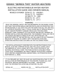
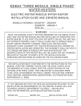
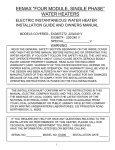
http://waterheatertimer.org/How-to-wire-Tankless-electric-water-heater.html
POWERSTAR PS19T / PS28T, SINGLE PHASE
WATER HEATERS
ELECTRIC INSTANTANEOUS WATER HEATER
INSTALLATION GUIDE AND OWNERS MANUAL
WARNING
READ THE GENERAL SAFETY SECTION BEGINNING ON THE INSIDE COVER
AND THEN THIS ENTIRE MANUAL BEFORE INSTALLING OR OPERATING THIS
WATER HEATER. IF YOU DON’T FOLLOW THE SAFETY RULES, THE UNIT WILL
NOT OPERATE PROPERLY AND IT COULD CAUSE DEATH, SERIOUS BODILY
INJURY AND/OR PROPERTY DAMAGE. READ ALSO THE ENCLOSED
WARRANTY CARD. WARRANTY OF THIS WATER HEATER WILL DEPEND ON
PROPER INSTALLATION AND OPERATION. THE WARRANTY SHALL BE VOID IF
THE DESIGN HAS BEEN ALTERED IN ANY WAY WHATSOEVER. THE
MANUFACTURER OF THIS HEATER WILL NOT BE LIABLE FOR ANY DAMAGES
BECAUSE OF FAILURE TO COMPLY WITH THE INSTALLATION AND
OPERATING INSTRUCTIONS OUTLINED ON THE FOLLOWING PAGES.
THE INSTALLATIONS AND SERVICE MUST BE PERFORMED BY A QUALIFIED
INSTALLER, SERVICE AGENT OR ELECTRICIAN. THE INSTALLATION MUST
CONFORM WITH THE INSTRUCTIONS IN THIS MANUAL; ELECTRIC COMPANY
RULES; AND THE LOCAL CODES, OR IN THE ABSENCE OF LOCAL CODES,
WITH THE LATEST EDITION OF THE NATIONAL ELECTRICAL CODE. UPON
COMPLETION OF THE INSTALLATION, THESE INSTRUCTIONS SHOULD BE
HANDED TO THE OWNER OF THE APPLIANCE FOR FUTURE REFERENCE.
IF YOU REQUIRE ANY HELP OR HAVE ANY QUESTIONS RELATING TO THE
INSTALLATION OR PERFORMANCE OF THIS HEATER, PLEASE CALL OUR
TECHNICAL SERVICE DEPARTMENT TOLL FREE : 1-800-642-3111.
PLEASE HAVE THE INFORMATION LISTED BELOW BEFORE CALLING :
SERIAL NO.
MODEL NO. PS
1
T
INSTALLATION DATE
GENERAL SAFETY
The PS19T and PS28T heaters are designed to take in cold water a nd heat it to temperatures
suitable for normal domestic usage up to a maximum of 140 F(60 C). These models are not
designed to be used as a sanitary booster which requires operating temperatures above 140
F(60 C) or for any recirculating type applications. To obtain optimum performance and energy
savings, these units should be located as near as possible to the point of use.
The units is supplied with compression rings and nuts suitable for direct coupling to standard
1/2” (5/8” outside diameter) copper piping. There is no need for additional screwed fittings and
under no circumstances use a blow torch on pipe while pipe is connected to the heater (serious
damage to the electronic flow switch will result).
Also, ensure that the pipes are clear of installation debris before fitting the heater.
THE PS19T HEATER MUST HAVE TWO DEDICATED INDEPENDENT
CIRCUITS AND THE PS28T MUST HAVE THREE DEDICATED
INDEPENDENT CIRCUITS, USING CORRECTLY RATED WIRES AND
CIRCUIT BREAKERS.
WARNING
FAILURE TO GROUND THE SYSTEM MAY RESULT IN DEATH OR SERIOUS INJURY.
WARNING
IMPROPER INSTALLATION, ADJUSTMENT, ALTERATION, SERVICE OR MAINTENANCE
CAN CAUSE DEATH, SERIOUS BODILY INJURY OR PROPERTY DAMAGE . REFER TO
THIS MANUAL FOR ASSISTANCE OR CONSULT THE LOCAL ELECTRIC UTILITY FOR
FURTHER INFORMATION.
WARNING
WATER HEATERS EQUIPPED FOR ONE VOLTAGE ONLY: THIS WATER HEATER IS
EQUIPPED FOR ONE VOLTAGE TYPE ONLY: CHECK THE RATING PLATE ON THE FRONT
COVER OF UNIT FOR THE CORRECT VOLTAGE. DO NOT USE THIS WATER HEATER WITH
ANY OTHER VOLTAGE OTHER THAN THE ONE SHOWN ON THE MODEL RATING PLATE.
FAILURE TO USE THE CORRECT VOLTAGE CAN CAUSE PROBLEMS WHICH CAN RESULT
IN DEATH, SERIOUS BODILY INJURY, OR PROPERTY DAMAGE. IF YOU HAVE ANY
QUESTIONS OR DOUBTS CONSULT CEC OR YOUR ELECTRIC COMPANY.
WARNING
HAZARD OF ELECTRICAL SHOCK! BEFORE REMOVING THE COVER OR SERVICING THE
WATER HEATER, MAKE SURE THE ELECTRICAL SUPPLY TO THE WATER HEATER IS
TURNED “OFF”. FAILURE TO DO THIS COULD RESULT IN DEATH, SERIOUS BODILY INJURY,
OR PROPERTY DAMAGE.
2
MODEL PS19T
MINIMUM - 8” CLEARANCE ABOVE UNIT
9”
serial #
TERMINAL
BLOCK
ELECTRICAL
HOOK-UP
240/208 V
MOUNTING
HOLES
POWER
INDICATOR
LIGHTS
G L1 L2 L1 L2
10“
TEMPERATURE
ADJUSTMENT
CONTROL
To 2 Independent
circuit breakers
4”
Outlet isolating valveball valve (leave open
just enough to obtain
adequate flow of hot water)
Inlet isolating valveball valve. (Always leave fully
open when unit is in service.)
3
MODEL PS28T
MINIMUM - 8” CLEARANCE ABOVE UNIT
12”
serial #
MOUNTING
HOLES
TERMINAL
BLOCK
ELECTRICAL
HOOK-UP
240/208 V
POWER
INDICATOR
LIGHTS
L1 L2 L1 L2 L1 L2
12 “
TEMPERATURE
ADJUSTMENT
CONTROLS
7’”
Outlet isolating valveball valve (leave open
just enough to obtain
adequate flow of hot water)
Inlet isolating valveball valve. (Always leave fully
open when unit is in service.)
4
To 3 Independent
circuit breakers
I. MOUNTING THE UNIT
1) The unit should be mounted as close to the point of use as possible. For example, directly
beneath the sink is ideal.
Do not install the heater above a faucet or “point of use” because the siphoning effect may
drain the heater which can cause premature element burn out.
2) This unit must only be mounted in a vertical position with the water fittings located at the
bottom of the unit. Mounting other than in the vertical position WILL cause element burn
out and cause permanent damage to the water heater.
3) The cold water inlet is on the right hand side and the hot water outlet is on the left hand side.
Under NO circumstances can these be reversed.
4) Leave a minimum of 8” above the unit for easy replacement of the element.
5) The heater should be fixed to the wall using screws in the fo ur mounting holes at each corner
of the backplate.
NOTE: The heater should be installed below the level of all hot water outlets serviced by this
heater.
NOTE: PRESSURE AND TEMPERATURE RELIEF VALVE
These units are not required by UL to have a Pressure and Temperature Relief
Valve (PTRV). You should check with local codes to find out if one is required in your
area.
If local codes require the use of a temperature and pressure relief valve it should be
installed on the outlet hot water pipe before the outlet ball valve.
DISCLAIMER
As a condition of installing this product in the Commonwealth of Massachusetts a pressure
relief valve shall be installed on the cold water side, by a licensed plumber MGL 142 Section 19
Approval number: P1-09-25
Showers and the whole house, cabin or condo
Lavatory
MODELS: PS19T / PS28T
Shower
Requirements:
Kitchen
About 0.85-2.5 GPM at showering temperature.
Best used when operating one outlet at a time.
Powerstar
Hot outlet
Cold inlet
5
II. PLUMBING HOOK-UP
1) The unit is supplied with compression fittings (Figure 1), USE THESE. DO NOT USE
TAPERED THREADED PIPE FITTINGS AND DO NOT SOLDER TO THE INLET OR
OUTLET. DO NOT USE ANY PIPE DOPE OR TEFLON TAPE WITH THESE
COMPRESSION FITTINGS.
2) Take care to ensure that the pipes are correctly aligned with the inlet and outlet bosses
in order to avoid excessive stress on the heater body molding.
NOTE: When soldering pipe joints remove heater from the wall. Serious damage can occur
if any soldering is done while pipes are connected to the heater.
Run water through the supply pipe to remove all debris from the pipe before
connecting the heater. Failure to do so could cause damage to the flow switch.
3) Install isolating valves (full flow ball valve type) on both inlet and outlet pipes. This allows unit
to be isolated for maintenance purposes.
4) When all plumbing is complete, fully check the system for water leaks at all the plumbing
connections. If a leak is present take corrective action. If the leak is at a compression fitting,
slowly tighten the compression nut until it stops. Fully open both inlet and outlet BALL VALVES.
Run all the hot water outlets fed by this heater one at a time, for a minute or two, until the water
flow is continuous, free from “gulping” and from all visible air pockets.
COLD INLET
FILTER SCREEN
Figure 1
HOT OUTLET
COMPRESSION
FITTING
DO NOT SOLDER
COLD INLET
COMPRESSION
FITTING
DO NOT SOLDER
NOTE:
ALL MOUNTING AND PLUMBING MUST BE COMPLETE BEFORE YOU
PROCEED WITH ELECTRICAL HOOK-UP.
TEST THE INSTALLATION FOR LEAKS BEFORE CONNECTING THE
ELECTRICAL SUPPLY.
6
III. ELECTRICAL HOOK-UP
WARNING
BEFORE BEGINNING ANY WORK ON THE ELECTRICAL INSTALLATION,
BE SURE THE SWITCH AT MAIN BREAKER PANEL IS “OFF” TO AVOID
ANY DANGER OF ELECTRICAL SHOCK.
MODEL TYPE OUTPUT / kW VOLTAGE / V AMPERAGE
PS19T
19
*240
2 X 40
PS28T
28
*240
3 X 40
* Units rated of 240 V can operate at 220 V or 208V with reduced output.
The output will vary in accordance with the following ratios:
volts
output ratio
208 volts 220 volts
.75
.84
240 volts
1.0
This unit must have its own independent circuits. (For PS19T use 2 SETS of UL listed 2 conductor
and ground core copper wire cable of the appropriate size protected by 2 separate and independent
correctly rated Double Pole breakers. See Figure 2). (For PS28T use 3 SETS of UL listed 2
conductor and ground core copper wire cable of the appropriate size, minimum 8GA wire size,
protected by 3 separate and independent correctly rated Double Pole breakers. See Figure 3).
Applies for 208, 220 or 240 V. Wire entry into the unit must be made through the hole provided in
the flange on the bottom.
The “live” wires should be connected to the slots in the terminal block marked L1 and L2. The
ground lead must be connected to the slot marked GND. GROUND MUS T BE BROUGHT TO
THE “GROUND” AT THE CIRCUIT BREAKER PANEL.
Figure 2
2 Separate and independent
correctly rated Double pole
breakers (240/208 Volts)
Figure 3
ON
ON
ON
OFF
OFF
ON
OFF
ON
OFF
OFF
ON
ON
ON
OFF
OFF
OFF
ON
OFF
Circuit Breaker Panel
ON
OFF
Circuit Breaker Panel
3 Separate and independent
correctly rated Double pole
breakers (240/208 Volts)
DANGER
FAILURE TO GROUND THE SYSTEM MAY RESULT IN DEATH OR SERIOUS INJURY.
7
IV COMMISSIONING YOUR HEATER
IMPORTANT
BEFORE SWITCHING “ON” THE POWER AT THE MAIN CIRCUIT BREAKER PANEL
MAKE SURE THAT THE HOT WATER CIRCUIT IS FREE OF AIR POCKETS OR ELSE
PREMATURE FAILURE OF THE ELEMENT WILL OCCUR. TO DO THIS OPEN ALL HOT
WATER OUTLETS ONE AT A TIME FOR A MINUTE OR TWO UNTIL THE WATER FLOW
IS CONTINUOUS AND FREE FROM “GULPING” AND FREE FROM VISIBLE AIR POCKETS.
1) Open fully both inlet and outlet valves at the heater.
2) Open fully the greatest hot water flowing outlet in the syste m. If the outlet is a “single lever”
mixer type turn to the hottest position. Run for one minute to clear all the air from the system.
3) Slowly close OUTLET ball valve until the water flow from the faucet just starts to reduce.
NOTE: This process has two effects. One, any air in the system will be purged out. Two, the
heater units will be pressurized at the supply pressure. This will prevent the elements burning
when energized.
(Note: Keep water flowing while carrying out the procedures outlined below.)
OPERATING UNIT AND SETTING WATER TEMPERATURE
a) Flow enough hot water to activate unit. The indicator light on the black flow control board
should illuminate.
b) Further increase the hot water flow and the indicator light o n the clear thermostatic board
to the left of the black board should illuminate. Note: This light should pulse On and Off at
first and after about 20- 30 seconds it should stay fully on.
c) Further increase the hot water flow and the indicator light o n the next clear thermostatic
board (PS28T model only) should illuminate. Note: This light should pulse On and Off at
first and after about 20- 30 seconds it should stay fully on.
d) Set (PS19T) thermostat to achieve the desired outlet temperature.
Set both (PS28T) thermostats to the same position to achieve the desired outlet temp.
e) The thermostat is now set and the water temperature will alwa ys be the same when the
indicator light is pulsing.
f) Increasing water flow (above the flow rate at which the thermostatic control is no longer
effective) will reduce the water temperature.
8
If a lower temperature is required for the PS19T, turn the temperature adjustment screw
counter-clockwise about 1/8 of a turn (See pages 3 & 4 for adjustment location). Wait 15-20
seconds and check the temperature at the fixture. Repeat this process until the desired
temperature has been achieved.
For PS28T model try to adjust the 2 temperature adjustment screws by about the same
amount so that the lights pulse at the same rate. If you have reduced the temperature
considerably from the 140 F setting, you could now open up the o utlet ball valve slightly to achieve
a higher rate of flow.
When the indicator light is on continuously, the unit is emitting full power. When it is pulsing, the
unit is modulating the power to achieve the temperature set by means of the temperature
adjustment screw.
In order to obtain good control at “single lever” mixer type faucets (single spout) the cold water
supply to the faucet should be restricted to give approximately the same flow rate of cold water
to the faucet as the hot water coming from your Powerstar heater. The simplest method of
doing this is by partially closing the cold water valve under the sink.
MAXIMUM TEMPERATURE RISE CHART ( 0F )
Add your inlet water temperature to the degree rise
to get the output temperature
MODEL
FLOW RATE ( GAL. PER MIN. )
1 1.5
2 2.5
3 3.5
4
PS19T
92
74
54
43
----
----
----
PS28T
78*
88
75
61
54
55
----
*At a 1 gallon per minute flow rate, only 2 of 3
elements in the PS28T will initiate. The 3 rd
element initiates with a slightly greater flow rate.
9
TROUBLESHOOTING
SYMPTOM: NO HEAT INDICATOR LIGHT OFF
Solution 1) ELECTRIC SUPPLY IS OFF
Turn on the main circuit breaker. NOTE: If unit has been out of operation, first make sure that
the hot water circuit is free of all air pockets or else premature failure of the element will occur.
Solution 2) INSUFFICIENT WATER FLOW
Insure that the minimum flow rate of 0.8 gpm to switch on your heater is met. 0.8 gpm is
equivalent to filling a quart container in 18 seconds. Also check that the inlet filter screen is
clear from any debris. This is located in the brass inlet boss (see Fig 1).
Solution 3) CROSSOVER IN PLUMBING
Cold water mixing with the hot outlet flow can back pressure the heater, test by isolating the
Heater. Shut off the cold inlet supply to unit and open a hot water tap. There should be no flow.
Solution 4) WATER CONNECTIONS ARE REVERSED
Cold water inlet = right side, hot water outlet = left side.
Solution 5) ELEMENT BURNED OUT
TURN OFF THE MAIN BREAKER!
Using an ohmmeter test the resistance of the heating element across
the two threaded termination rods on top of the element. The
resistance reading should be under 10 ohms. If the resistance is
much greater than this value, call CEC for a replacement element.
SYMPTOM: NO HEAT OR LOW TEMPERATURE WITH
INDICATOR LIGHT ON
Solution 1) WATER FLOW TOO HIGH
Reduce the water flow by using an outlet ball valve. See page 9 for temperature rise at various
flow rates.
Solution 2) INCORRECT POWER SUPPLY
Make sure that the unit is connected to the voltage supply specifiedon the rating label on the the
front cover of the unit and no other.
Solution 3) ELEMENT BURNED OUT
TURN OFF THE MAIN BREAKER!
Repeat the steps from Solution 5 above.
Solution 4)THERMOSTAT ADJUSTMENT SCREW NOT TURNED UP
Turn thermostat adjustment screw(s) clockwise in small increments until the indicator light(s)
remain on. Take care not to force the screw past its stop position.
10
PS19T REPLACEMENT PARTS DIAGRAM
serial #
TRIAC - EX 18
REPLACEMENT HEATER
CORE ASSEMBLY
EX630 - 9.5 KW @ 240 V
Terminal Block
electrical hook-up
240/208 V
G L1 L2 L1 L2
BLACK FLOW
CONTROL BOARD
EX 101/240
CLEAR
THERMOSTATIC
CIRCUIT BOARD
EX 100/240
INLET FILTER SCREEN
EX 65
To 2 Independent
circuit breakers
INLET
CEC, 340 Mad River Park, Waitsfield, VT 05673
11
800-642-3111
PS28T REPLACEMENT PARTS DIAGRAM
serial #
TRIAC - EX 18
REPLACEMENT HEATER
CORE ASSEMBLY
EX630 - 9.5 KW @ 240 V
TERMINAL
BLOCK
ELECTRICAL
HOOK-UP
240 V
BLACK FLOW
CONTROL
BOARD
EX 101/240
L1 L2 L1 L2 L1 L2
CLEAR
THERMOSTATIC
CIRCUIT BOARD
EX 100/240
INLET FILTER SCREEN
EX 65
INLET
CEC, 340 Mad River Park, Waitsfield, VT 05673
12
To 3 Independent
circuit breakers
800-642-3111
POWERSTAR •
LIMITED 10 YEAR WARRANTY
COVERAGE
THE MANUFACTURER THROUGH ITS
DISTRIBUTOR CONTROLLED ENERGY CORP.,
(hereinafter CEC) guarantees this water heater to
the Owner (hereinafter "Owner") of the water heater
at the original installation location against defects in
material and workmanship for the periods specified
below.
WARRANTY PERIOD
1.
2.
3.
The Heat Modules - If the original heat module(s)
leaks within ten (10) years from the date of original
installation of the water heater, because of a defect
in material or workmanship, CEC will furnish to such
Owner a new heater of the then prevailing
comparable model.
Any Component Part Other than The Heat
Modules - If any other component part (other than
the heat modules) proves to be defective in material
or workmanship within one (1) year from the date of
original installation of the water heater, CEC will
furnish the Owner with a replacement of the
defective part(s).
Verification of Date of Original Installation - When
Owner cannot verify or document the original date of
installation, the warranty period begins on the date of
manufacture marked on the serial number tag affixed
to water heater.
EXCLUSIONS
1.
2.
3.
THIS LIMITED WARRANTY SHALL BE THE
EXCLUSIVE WARRANTY MADE BY THE
MANUFACTURER AND IS MADE IN LIEU OF ALL
OTHER WARRANTIES, EXPRESSED OR IMPLIED
(WHETHER WRITTEN OR ORAL), INCLUDING,
BUT NOT LIMITED TO, WARRANTIES OF
MERCHANTABILITY AND FITNESS FOR A
PARTICULAR PURPOSE.
Manufacturer shall not be liable for any incidental,
consequential, special or contingent damages or
expenses arising, directly or indirectly, from any
defect in the water heater or the use of the water
heater.
Manufacturer shall not be liable for any water
damage arising, directly or indirectly, from any defect
in the water heater component part(s) or from its
use.
4. manufacturer shall not be liable under this warranty
if:
a) The water heater or any of its
component parts has been subject to
misuse, alteration, neglect or
accident, or
b) The water heater has not been
installed in accordance with the
applicable local plumbing and/or
building code(s) and/or regulation(s),
or
c) The water heater has not been
installed in accordance with the printed
manufacturer's instructions, or
d) The water heater is not
continuously supplied with potable
water.
5. The OWNER and not the Manufacturer or his
representative shall be liable for and shall pay for all
field charges for labor or other expenses incurred in the
removal and/or repair of the product or any expense
incurred by the owner in order to repair the product.
SOME STATES DO NOT ALLOW THE EXCLUSION
OR LIMITATION OF INCIDENTAL OR
CONSEQUENTIAL DAMAGES, SO THE ABOVE
LIMITATION OR EXCLUSION MAY NOT APPLY TO
YOU. THIS WARRANTY GIVES YOU SPECIFIC
LEGAL RIGHTS AND YOU MAY ALSO HAVE OTHER
RIGHTS WHICH MAY VARY FROM STATE TO
STATE.
NOTE: A water heater should be installed in such a
manner that if it should leak, the resulting flow of water
will not cause damage to the area in which it is installed.
HOW THE OWNER CAN SECURE SERVICE OR
MAKE A CLAIM
1. Owner should contact the dealer who sold the water
heater covered by this warranty or
2. Owner should submit the warranty claim directly to
CEC at the address listed below, and they will arrange
for the handling of the claim
3. Whenever any inquiry or service request is made, be
sure to include the water heater model number the date
of manufacture, date of installation, Dealer's name and
the watts and voltage.
4. When returning the water heater or component
part(s), they must be individually tagged and identified
with the Returned Goods Authorization # issued by CEC
and shipped prepaid to CEC.
04/02