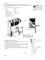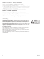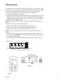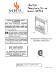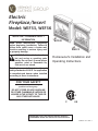
1
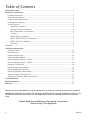
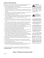
Electric
Fireplace/Insert
Model: WEF33, WEF36
INSTALLER / CONSUMER SAFETY
INFORMATION
Read these instructions completely
before beginning installation. Failure to
follow them could cause a heater malfunction resulting in serious injury and/
or property damage.
WARNING: All electric heaters have
hot and arcing or sparking parts
inside. Do not use it in areas where
gasoline, paint or flammable liquids are or are stored.
This fireplace meets the construction and
safety standards of H.U.D. for application
in manufactured homes when installed
according to these instructions.
WEF36
WEF33
Homeowner's Installation and
Operating Instructions
WEF33 36 cover
FOR YOUR SAFETY
Service must be performed by a
qualified service agency.
DO NOT STORE OR USE GASOLINE
OR OTHER FLAMMABLE VAPORS OR
LIQUIDS IN THE VICINITY OF THIS OR
ANY OTHER APPLIANCE.
C
US
INSTALLER: Leave this manual with the appliance.
CONSUMER: Retain this manual for future reference.
68D5301 2/13 Rev. 4
Table of Contents
Safety Information.................................................................................................................. 3
Installation Instructions
Fireplace Dimensions.......................................................................................................... 4
Fireplace Parts Identification................................................................................................ 4
Electrical Specifications....................................................................................................... 4
Locating Your Fireplace....................................................................................................... 5
Install Fireplace.................................................................................................................... 6
Installing in a Mantel...................................................................................................... 6
New Construction or Renovation..................................................................................... 6
Existing Fireplace Installation......................................................................................... 6
Framing.......................................................................................................................... 7
Nailing Flange Installation.............................................................................................. 7
WEF33, WEF36 120V AC Installation............................................................................... 8
WEF36 240V AC Installation............................................................................................ 8
Finishing........................................................................................................................ 8
Operation.................................................................................................................................. 9
Cleaning & Maintenance
Cleaning Firebox................................................................................................................ 10
Replacing Ember Strip........................................................................................................ 10
Replacing Log.................................................................................................................... 10
Replacing Heater/Blower.................................................................................................... 11
Electrical Wiring Diagram - WEF33..................................................................................... 12
Electrical Wiring Diagram - WEF36..................................................................................... 13
Replacing Transformer....................................................................................................... 14
Replacing Main Control Board............................................................................................ 14
Replacing Backlight LED Strip............................................................................................. 14
Replacing Settings Control Board....................................................................................... 14
Replacing Flame Generation LED........................................................................................ 15
Cleaning or Replacing Back Screen (Glass).......................................................................... 15
Troubleshooting.................................................................................................................... 16
Replacement Parts................................................................................................................ 17
Warranty................................................................................................................................ 19
Thank you and congratulations on your purchase of an Vermont Castings Group electric fireplace.
IMPORTANT: Read all instructions and warnings carefully before starting installation. Failure to follow these instructions may result in a possible electric shock, fire hazard and will void the warranty.
Please Read the Installation & Operating Instructions
Before Using This Appliance
68D5301
Safety Information
When using electric heaters, basic precautions should always be followed to reduce
the risk of fire, electric shock and injury to person, including the following:
1. Read all instructions before using this appliance.
2. Keep combustible materials, such as furniture, pillows, bedding, papers, clothes
and curtains away from front of heater.
3. This heater is hot when in use. To avoid burns, do not allow bare skin to touch
hot surfaces. The grille directly in front of heater outlet becomes hot during heater
operation.
4. Extreme caution is necessary when any heater is used by or near children or
invalids and whenever heater is left operating and unattended.
5. Always unplug heater when not in use.
6. Do not operate any heater with a damaged cord or plug or if heater malfunctions
or has been dropped or damaged in any way. Return heater to authorized service
facility for examination, electrical or mechanical adjustment or repair.
7. Do not use outdoors.
8. This heater is not intended for use in bathrooms, laundry areas and similar indoor
locations. Never locate heater where it may fall into a bathtub or other water container.
9. Do not run cord under carpeting. Do not cover cord with throw rugs, runners or the
like. Arrange cord away from traffic area and where it will not be tripped over.
10. To disconnect heater, turn controls to OFF before removing plug from outlet.
11. Do not insert or allow foreign objects to enter any ventilation or exhaust opening
as this may cause an electric shock or fire or damage the heater.
12. To prevent possible fire, do not block air intakes in any manner. Do not use on soft
surfaces, like a bed, where openings may become blocked.
13. Always use properly grounded, fused and polarized outlets.
14. A heater has hot and arcing or sparking parts inside. Do not use it in areas where
gasoline, paint or flammable liquids or vapors are used or stored.
15. Use this heater only as described in this manual. Any other use not recommended
by the manufacturer may cause fire, electric shock or injury to persons.
16. Avoid the use of an extension cord because the extension cord may overheat and
cause a risk of fire. However, if you have to use an extension cord, the cord should
be No. 14AWG minimum size and rated not less than 1875 watts.
17. Always use ground fault protection where required by electrical codes.
18. Always disconnect power before performing any cleaning, maintenance or relocation of heater.
19. To prevent a possible fire, do not burn wood or other materials in this heater.
20. To prevent electric shock or fire, always use a certified electrician should new
circuits or outlets be required.
21. When transporting or storing heater, keep in a dry place.
22. Control panel door gets hot during heater operation. Open door by pressing on
right corner. A spring magnet will disengage. Pull door down to open.
WARNING:
Improper installation,
adjustment, alteration, service or maintenance
can cause injury or property
damage. Refer to this manual. For assistance or additional information, consult a
qualified installer.
CAUTION: Do not
expose the heater
to the elements
(such as rain, etc.).
— Do not place clothing or
other flammable material on
or near firebox. Never place
any objects on the fireplace.
— Carefully supervise young
children when they are in the
room with the fireplace.
— Fireplace becomes very
hot when running. Keep children and adults away from
hot surfaces to avoid burns
or clothing ignition. Fireplace
will remain hot for a time after shutdown. Allow surfaces
to cool before touching.
— Do not install fireplace
directly on carpet or similar
surface which may restrict
air circulation beneath unit.
NOTE: This heater must
be electrically wired and
grounded in accordance
with local codes or, in the
absence of local codes, with
National Electric Code ANSI/
NFPA 70-latest edition or the
Canadian Electric Code,
CSA C22.1 as appropriate.
This heater has been tested in accordance with the CSA Standards for fixed and
location-dedicated electric room heaters in the United States. All components are UL
or CSA safety certified.
Save These Instructions
68D5301
Installation Instructions
• WEF Fireplace Dimensions
226M” (578 mm)
226M” (578 mm)
10”
(254 mm)
10”
(254 mm)
3356” (841 mm)
3756O” (953 mm)
3356” (841 mm)
3556O” (902 mm)
34”
(864 mm)
32(6”
(835 mm)
WEF36 WEF33
Figure 1
NOTE: This heater must
be electrically wired and
grounded in accordance
with local codes or, in the
absence of local codes,
with National Electric Code
ANSI/NFPA 70-latest edition or the Canadian Electric Code, CSA C22.1 as
appropriate.
Electrical Specifications
Voltage
Total Amps
Total Watts
Heater Rating
WEF33
WEF36
120V AC, 60 Hz
120/240V AC, 60 Hz
15
15 / 20
685301
WEF 33/36 dims 1500 / 3000
1500
1400 Watts
2800 Watts
• WEF Fireplace Parts Identification
Control
Panel Door
Remote Hide
Handle
Magnetic
Catch
ON/OFF
Power Switch
Heat Vents
(behind doors)
Power
Heater
Front Glass
Rear Glass
(Screen)
Heater
Control
Flame Control
Flame
Ember
Backlight
Backlight Control
Ember Control
Remote
Figure 2
WEF36 Shown
Log Set
FP2569
68D5301
CAUTION: The unit's
power supply cord
• Unpacking and Testing
must be connected to
a properly grounded and proWEF33
Carefully remove unit from box. Prior to permanently installing unit, test to make sure tected 120 Volt outlet. Always
use ground fault protection
unit operates properly. To do this, plug unit's power cord into a conveniently located
where required by the electri120 Volt grounded outlet.
cal code.
WARNING: Do not
WEF36
operate the unit if it is
Carefully remove unit from box. Prior to permanently installing unit, test to make sure
damaged or has malunit operates properly. Unit does not come with the power cord installed. Unit must
functioned. If you suspect the
be hard-wired to either a 120/60 or 240/60 volt supply.
unit is damaged, return the unit
to an authorized service facil• Locating Your Fireplace
ity for examination, electrical
or mechanical adjustment or
This electric fireplace can be installed in a mantel, framed into a wall or installed
into an existing fireplace. If installing into a mantel, follow mantel's assembly instruc- repair.
tions. Figure 3 illustrates a variety of ways the heater may be located in a room. The
WARNING: Due to
heater may be installed directly on the floor or raised on a hearth.
high temperatures,
)
59 22”
m
m
)
Corner Mantel
Installation
44
” (
11
18
m
m
(5
3156” (791 mm)
3156” (791 mm)
Wall Mantel
Installation
Framed
into
Wall or
Existing
Fireplace
FP2388
Figure 3
FP2388 WEF33/36
locate fireplace
68D5301
this heater should
be located out of traffic. Keep
combustible materials such as
furniture, pillows, bedding, papers, clothes and curtains at
least 3 feet (914 mm) from the
front of the heater.
WARNING:
Never
locate this heater
where it may fall into
a bathtub or other water container.
NOTICE: Minimum and maximum clearances must be maintained at all times. Illustrations
throughout these instructions
reflect typical installation and
are for design purposes only.
Actual installations may vary
slightly due to individual preferences.
WARNING: To prevent contact with sagging or loose insulation, the heater must
not be installed against vapor
barrier or exposed insulation.
Localized overheating could
occur and a fire could result.
CAUTION: Do not
expose the heater to
the elements (such
as rain, etc.)
CAUTION:
Wear
gloves and safety
glasses for protection
during installation and maintneance.
• Install Fireplace
Select a suitable location that is not susceptible to moisture and is a safe distance
from drapes, furniture and high traffic areas.
NOTE: Follow all national and local electrical codes. This insert can be installed into
either an existing fireplace or as a new construction/renovation.
• Installing in a Mantel
1. Assemble mantel according to mantel instructions.
2. Locate mantel near a wall (or corner depending on mantel type) close to a power
source. You may have to alter base boards to fit mantel flush against wall.
3. Insert fireplace into front of mantel. Be careful not to scratch finish on base.
Fireplace will fit flush against front of mantel.
4. Plug fireplace into power source. Push mantel with fireplace into final location.
NOTE: The Vermont Castings Group Barrington Cabinet Mantel Model series BWC300,
BWC400 and BWC500 are specially designed to comply with all mantel temperature
requirements. Any custom-built mantel must comply with all clearance requirements
shown in this instruction manual.
• Existing Fireplace Installation
1. Thoroughly clean out existing fireplace and hearth area.
2. Seal all drafts, vents or ash clean-outs with fiberglass insulation. Seal flue. Once
sealed, close damper to stop debris from falling onto unit.
3. If existing firebox is susceptible to moisture, cap top of chimney flue to prevent
infiltration of water.
NOTE: It is strongly advised that you hire a qualified professional to undertake this
step in order to prevent personal injury. Once flue is capped, chimney is no longer
suitable for wood burning.
NOTE: Do no install this unit into a fireplace that is prone to dampness; the area of
installation must be dry.
4. Plan the power supply. If an existing grounded outlet is near fireplace, power
cord can run along front of fireplace. If cord is not long enough to reach outlet,
a grounded extension cord minimum 14 AWG and rated to a minimum of 1875
watts, may be used. If you plan to cut or drill a hole in existing fireplace for wiring, it is best to hire a professional to do this step in order to prevent personal
injury. To reduce the risk of fire, do not run power cord under rugs, carpets, etc.
Arrange power supply cord away from high traffic areas where it may pose a tripping hazard.
• New Construction or Renovation
1. Select a location away from combustible materials such as curtains or drapes,
furniture, bedding, paper, etc.
2. Mark desired location on floor and store unit in a safe, dry and dust free location.
3. Frame in an opening leaving at least 1/4" (6 mm) around the edge of the unit
(refer to Framing). Any new wiring must be done in compliance with local and
national codes and other applicable regulations in order to reduce the risk of fire,
electric shock or other injuries. Therefore, it is strongly recommended that you
hire a professional to complete any such work.
4. Plan your power supply route. Refer to Step 4 Existing Fireplace Installation.
WARNING - RISK
OF FIRE! The power cord must not be
pinched or against a sharp
edge. Secure cord to avoid
tripping or snagging to reduce
the risk of fire, electric shock
or personal injury.
— Do not run cord under carpeting. Do not cover cord with
throw rugs, runners or the
like. Arrange cord away from
traffic areas and where it will
not be tripped over.
WARNING - RISK
OF FIRE! To prevent
a possible fire, do
not block air intake or exhaust
in any manner. Do not use on
soft surfaces where openings
may become blocked.
WARNING - RISK
OF FIRE! Do not
blow or place insulation against the firebox.
WARNING: If the
information in these
instructions is not
followed exactly, a fire or explosion may result causing
property damage, personal
injury or death.
— Do not store or use gasoline or other flammable vapors in the vicinity of this or
any other heater.
WARNING: The solid fuel/gas fireplace
has been converted
for use with an electric insert
and cannot be used for original fuels unless all original
parts have been replaced and
the fireplace has been reapproved by the authority having jurisdiction.
68D5301
• Framing
Figure 4 shows a typical framing of the heater using combustible materials. All
required clearances to combustibles must be adhered to. Header height is measured
from the base of the heater.
CAUTION: Provide
adequate
clearances around the
air openings and adequate
accessibility clearances for
servicing and proper operations.
Tools and building supplies required for installation:
• Saw
•
• Pliers
•
• Hammer
•
• Philips screwdriver •
• Framing materials •
• Tape measure
• Wall-finishing materials
• Caulking material
Square
Gloves
Level
Surround
Electric drill/bits
12”
10"
8”
Figure 4
11”
6”
106M”
4”
956O”
256O”
856M”
7”
6”
Top of Fireplace
Opening
3256O”
FP2390
FP2570
3456O”
1056O”
NOTE: The height that a combustible mantel is fitted above the
heater is dependent on the height
of the front selected. The minimum
height is 1" above the front.
FP2390
mantel depth
• Nailing Flange Installation
FP2570
1. The fireplace has an adjustable
nailing flange that will accommodate wall
framing
installations from 1/2" to 1Z\x" thick.
2. Secure the nailing flange to the framing member. It is recommended to
remove the front face of the fireplace when nailing the flange to the wall.
Refer to the cleaning and maintenance section.
3. The nailing flange can be adjusted front to back by loosening the screw
that secures the nailing flange to the fireplace. Do not remove the screw
completely.
Adjustable
Nailing Flange
Figure 5
FP2571
68D5301
• WEF33 and WEF36 - 120V AC Installation
Once the site has been prepared, your fireplace can be installed.
1. Make sure power switch is in the OFF position.
2. Plug fireplace into a 15-amp/120 Volt, grounded outlet. For WEF36, you will need
to purchase WEFCORD and connect to the wiring as a 120 volt AC, before plugging into a 15 amp/120 volt, grounded outlet.
3. Push fireplace insert so trim is against finished mantel or wall surface.
• WEF36 - 240V AC Installation
1. Loosen the screw securing the junction box cover and remove cover.
2. Complete the wiring following the wiring diagram on the box or in the homeowner's manual.
3. Make sure this wiring has a dedicated 20 amp fuse.
4. Place all connectors inside the fireplace and replace junction box cover.
• Finishing
Combustible Finishing Material - Materials made of or surfaced with wood, compressed paper, plant fibers, plastics or any material capable of igniting and burning,
whether flame proofed or not, plastered or unplastered (this includes drywall).
Noncombustible Finishing Material - Materials which will not ignite and burn. Such
materials are those consisting entirely of steel, iron, brick, tile, concrete, slate, glass
or plasters or combinations thereof or have a fire rating of zero.
WARNING: Control panel door on
this heater cannot,
in any way, be covered as it
may create a fire hazard.
• Finishing Checklist
Power supply service must be completed prior to finishing to avoid reconstruction.
Grilles and air openings cannot be covered under any circumstances.
NOTE: The heater is a zero clearance fireplace and may be finished with combustible or noncombustible finishing materials.
When using paint or lacquer to finish the mantel, they must be heat resistant to prevent discoloration.
68D5301
Operation
The controls are located behind the hinged control panel door. If using heater, control
panel door will be hot during and immediately after operation. Open door by pressing
on right side. A spring magnet will push door forward. Pull door down to open.
1. Plug in electric fireplace or if hard-wired to 240V AC, turn switch on.
2. Turn on lighted power switch. Figure 6
3. Adjust Flame/Ember/Backlight/Heater to desired settings using the control pad on
fireplace (Figure 6) or remote control. Figure 7. Figure 8 shows fireplace settings
available. Default settings are circled. Press control pad or remote control buttons
once and release to adjust settings.
NOTE: When on, ember bed will lighten and darken automatically to simulate real
embers.
The heater is pre-set to the following temperatures.
• High will shut off when room reaches approximately 86°F (30°C).
• Medium will shut off when room reaches approximately 79°F (26°C).
• Low will shut off when room reaches approximately 72°F (22°C).
NOTE: Fan on heater will continue to run for 5-7 seconds after heater has been
turned off.
4. When using remote control, aim remote at sensor located in center of unit just
above the log set. IMPORTANT: This remote control must remain within 20 feet (6
m) of fireplace to be effective.
5. When power switch is turned off, fireplace settings go back to default. Figure 8
Figure 6
Power
Heater
Flame
Ember
Backlight
FP2391
Heater Control
Flame
Control
Ember
Control
Lighted Power
Switch
Backlight Control
FP2391
controls
Fireplace Settings
(Default settings are circled)
POWER
FLAME
EMBER
HEATER
Off
Low Medium
High
FLAME
Off
Low
Medium
High
EMBER
Off
Low
Medium
High
BACKLIGHT
Off
Low High
Figure 8
BACKLIGHT HEATER
Figure 7
68D5301
FP2392
Remote control
Cleaning & Maintenance
To service electric fireplace, it may be necessary to remove it from the mantel or enclosure in which it is installed. Allow unit to cool completely before cleaning or servicing.
• Cleaning Firebox
1. Open control panel door by pressing on right side. a spring magnet will push door
forward. Pull door down to open.
2. Remove two (2) screws holding front trim in place. Pull gently to remove trim.
Figure 9. There are magnets on the lower portion of trim. Figure 9
3. With gloves and safety glasses in place, remove four (4) screws from glass retainer brackets. Figure 9
4. Carefully remove front glass and brackets. Figure 10
5. Using a brush vacuum attachment, gently clean compartment.
6. After cleaning compartment, replace front glass, brackets and trim.
WARNING:
Always disconnect
power and allow
the heater to cool before
performing any cleaning,
maintenance or relocation
of this heater. Turn controls
to OFF and remove plug
from outlet or turn off circuit
breaker to heater.
Trim
• Replacing Log
1. Follow Steps 1 through 4 of 'Cleaning Firebox'.
2. Remove screws from each side of log securing log to sides
and remove log. Figure 11
3. Install new log using screws removed in Step 2.
4. Replace front glass and brackets.
5. Replace trim.
• Replacing Ember Strip
1. Follow Steps 1 and 2 of 'Replacing Log'.
2. Locate ember LED strip, Figure 11. Disconnect wire (right
side).
3. Remove ember LED strip by squeezing top of standoffs
and discard.
4. Connect new ember LED strip using existing standoffs.
5. Reconnect wire to LED strip.
10
FP2573
replace log
68D5301
6. Follow Steps 3 through 5 of 'Replacing Log'.
• Replacing Heater/Blower
1.
2.
3.
4.
5.
6.
7.
8.
Follow Steps 1 through 4 of 'Cleaning Firebox'.
Remove screws from around top panel of firebox. Figure 12
There are several wires attached to the top panel. Carefully lift top panel.
Disconnect heater/blower wires from main circuit board.
Remove screws holding heater/blower to top panel. Figure 12
Remove brackets from heater/blower. Figure 13. Save brackets and screws.
To remove heater from blower, remove four (4) screws (2 per side).
If replacing blower, remove screws from brackets on blower. Figure 13. Install
brackets to new blower.
9. Replace blower or heater. Replace screws removed in Step 7.
10. Hold heater/blower with brackets in place against top panel and replace screws
removed in Step 5.
11. Reconnect wires to main circuit board. Figure 15 or 16
12. Replace glass with brackets and top panel.
Screws Securing
13. Replace trim.
Heater/ Blower
Top Panel
Screws
Figure 12
FP2396
Brackets
Figure 13
FP2396
remove top panel
Figure 14
Blower
Heater
FP2398
FP2397
FP2397
remove brackets
68D5301
FP2398
separate blower heater
11
• Electrical Wiring Diagram - WEF33
Any electrical repairs or rewiring of this unit should be carried out by a licensed
electrician in accordance with national and local codes.
FP2574
WEF33 wiring
Figure 15
WEF33 Wiring Diagram
WARNING: Disconnect Power Before Servicing
If repairing or
replacing
any
electrical component or wiring, the original
wire routing, color coding and securing locations
must be followed.
Any
electrical
re-wiring of this
appliance must be
done by a qualified electrician. This wiring must
be done in accordance
with local codes and/or
in Canada with the current CSA C22.1 Canadian
Electrical Code, and for US
installations, the National
Electrical Code ANSI/NFPA
NO 70.
12
68D5301
• Electrical Wiring Diagram - WEF36
Any electrical repairs or rewiring of this unit should be carried out by a licensed
electrician in accordance with national and local codes.
Figure 16
WEF36 Wiring Diagram
WARNING: Disconnect Power Before Servicing
FP2575
WEF36 wiring
68D5301
If repairing or
replacing
any
electrical component or wiring, the original
wire routing, color coding and securing locations
must be followed.
Any
electrical
re-wiring of this
appliance must be
done by a qualified electrician. This wiring must
be done in accordance
with local codes and/or
in Canada with the current CSA C22.1 Canadian
Electrical Code, and for US
installations, the National
Electrical Code ANSI/NFPA
NO 70.
13
• Replacing Transformer
1. Follow Steps 1 through 3 in 'Replacing Heater/Blower'.
2. Disconnect transformer wires from control board.
3. Remove screws and nuts from firebox surround to remove
transformer. Figure 17
4. Remove and discard transformer.
5. Place new transformer against inside of firebox surround and
replace screws and nuts removed in Step 3.
6. Reconnect transformer wires to control board. Refer to Wiring
Diagram, Figure 15 or 16.
7. Replace glass with brackets, and top panel.
8. Replace trim.
Figure 17
Transformer
Nuts
Screws
FP2400
• Replacing Main Control Board
1.
2.
3.
4.
5.
Follow Steps 1 through 3 in 'Replacing Heater/Blower'.
Disconnect wires to main control board.
Squeeze top of standoffs to remove main control board and discard.
Gently push new control board onto standoffs to install.
Reconnect wires to main control board. Refer to Wiring Diagram,
Figure 15 or 16.
6. Replace glass with brackets and top panel.
7. Replace trim.
Transformer
Main Control
Board
Figure 18
• Replacing Backlight LED Strip
1.
2.
3.
4.
5.
Follow Steps 1 and 3 in 'Replacing Heater/Blower'.
Disconnect wires from main control board.
Squeeze top of standoffs to remove backlight LED strip and discard.
Place new backlight LED strip onto standoffs and push gently.
Connect wires to main control board. Refer to Wiring Diagram, Figure 15
or 16.
6. Replace glass with brackets and top panel.
Standoffs
FP2400
remove transformer
FP2401
FP2401
Figure 19
Standoffs
remove control board
Backlight
LED Strip
FP2402
• Replacing Settings Control Board
1.
2.
3.
4.
Follow Steps 1 through 3 in 'Replacing Heater/Blower'.
Disconnect wires from main control board.
Remove screws from bracket to remove settings control board.
Place new settings control board into position making sure each control
is aligned with slot in panel. Install using screws from Step 3. DO NOT
overtighten. This will damage control board.
5. Reconnect wires to main control board. Refer to Wiring Diagram, Figure
15 or 16.
6. Replace glass with brackets and top panel.
7. Replace trim.
Figure 20
Screws
FP2402
replace backlight LEDSettings
Control
Board
FP2403
68D5301
14
FP2403
• Replacing Flame Generation LED
1.
2.
3.
4.
5.
Follow Steps 1 through 4 in 'Cleaning Firebox'.
Remove screws securing log to either side of base. Remove log. Figure 11
Remove screws from sides and back of bottom panel of firebox.
Gently lay unit on its back.
White Wire
There are several wires attached to bottom panel. Carefully
remove panel.
6. Disconnect wires from motor and LED drum assembly.
7. Remove screws from bottom panel to remove assembly.
Figure 21
8. Hold LED drum assembly in place on bottom panel and
replace screws.
9. Reattach wires to motor and LED drum. NOTE: LED drum
Screws
wires are polarity sensitive and must be connected correctly.
White wire plugs onto left terminal and red wire plugs onto
right terminal. Motor wires can be connected to either terminal.
10. Replace fireplace bottom panel. Set fireplace upright and
replace screws.
11. Replace log, glass and brackets.
12. Reinstall fireplace and replace trim.
• Cleaning or Replacing Rear Glass (Screen)
Red Wire
LED Drum
Assembly
Motor
FP2404a
FP2404a
flame LED drum
1. The glass is cleaned in the factory during assembly. During shipment, installation,
handling, etc., glass surface may collect dust particles. These can be removed by
buffing lightly with a clean damp cloth (water only). Glass should be completely
dried with a lint free cloth or paper towel.
2. In the event of glass breakage, vacuum all remaining glass pieces with a shop
vac. DO NOT VACUUM WHILE PIECES ARE HOT. Replace glass only with
replacement part specifically for this heater. Never substitute material. Only fully
tempered soda lime safety glass may be used on this heater.
3. To access glass to clean or replace, follow Steps 1 and 7 in 'Replacing Flame
Generation LED'. Set aside bottom panel.
4. Using gloves, gently remove glass panel by sliding it toward you. There is a rubber bumper on each corner of glass.
5. Clean glass as instructed in Step 1 or replace glass.
6. Using gloves, reinstall glass by gently sliding, smooth side toward fireplace front,
into brackets on either side that hold glass in place.
7. Replace log base.
8. Follow Steps 11 and 14 in 'Replacing Flame Generation LED'.
68D5301
15
Troubleshooting
Problem
1. Fireplace turns off
and will not turn
on.
Possible Cause
1. Fireplace has overheated
and safety devise has caused
thermal switch to disconnect
or home circuit breaker has
opened.
Solution
1. Reset switch by turning main
power switch off and waiting 5
minutes then turning it back on
or reset circuit breaker.
2. Flame is not moving.
1. Loose wiring.
1. Inspect wiring for loose connections.
2. Call a qualified service technician to replace flame motor.
3. Flame is not visible.
1. Wiring is loose.
1. Disconnect from power source
and inspect wiring for loose
connections and repair or
replace if necessary.
4. Log set and/or ember is not glowing.
1. Wiring is loose.
1. Disconnect from power source
and inspect wiring for loose
connections and repair or
replace if necessary.
5. Flame sputters/
flashes.
1. Flame motor is defective.
1. Call a qualified service technician to replace flame motor.
2. Disconnect power. Follow
steps to replace flame generation LED. Clean contacts with
dry cloth.
6. Remote control
does not work.
1. Low batteries.
2. Flame motor defective.
2. Flame generation contacts
dirty/obstructed.
2. Not aiming control correctly.
3. Defective remote control and
/or sensor.
7. Fireplace will not
come on when
switch is flipped to
ON.
1. Fireplace is not plugged in to
an electrical outlet.
2. Control failure.
8. Heater does not
provide heat when
turned on.
1. Thermal switch has been
tripped.
3. Breaker tripped.
2. Circuit breaker has been
tripped.
3. Wiring is loose.
4. Heater is defective.
5. Thermostat cycled off.
16
WARNING: Turn
off appliance and
allow to cool before
servicing. Only a qualified
service person should service and repair heater.
1. Replace AAA batteries in
remote control.
2. Aim control at sensor located
directly behind glass screen in
center of unit just above logs.
3. Replace remote control and/or
sensor.
1. Check plug.
2. Call a qualified service technician.
3. Reset breaker.
1. Turn unit off and unplug unit
for 5 minutes. Plug back in and
turn unit on. If plug cannot be
reached, follow directions for
tripped circuit breaker.
2. Turn off circuit breaker that
supplies electricity to unit.
Wait 5 minutes then flip circuit
breaker back on.
3. Disconnect from power source
and inspect wiring for loose
connections and repair or
replace if necessary.
4. Replace heater.
5. Change to higher setting.
68D5301
Replacement Parts
Vermont Castings Group reserves the right to make changes in design, materials, specifications, prices and discontinue colors and products at
any time, without notice.
WEF33, WEF36 Electric Fireplace
Ref. Description
1.
2.
3.
4.
5.
6.
7.
8.
Blower (Motor and Fan)
Rear Glass (Screen)
Log Set
Flame Effect Mirror
Handles
Main Control Board and Standoffs (5)
Transformer
Heater
68D5301
Qty.
1
1
1
1
2
1
1
1
WEF33
68D5101
68D5202
68D5203
68D5204
68D5105
68D5106
68D5107
68D5108
WEF36
68D5201
68D5202
68D5203
68D5204
68D5105
68D5206
68D5207
68D5208
17
WEF33, WEF36 Electric Fireplace
Ref. Description
9. Settings Control Board
10. LED Drum Assembly
11. LED Ember Strip
12. Remote Control
13. Remote Control Sensor
14. Power Cord
15. ON/OFF Switch
16. Front Glass
17. Control Panel Door (black)
18. Top (black)
19. Front Trim
20. Magnetic Catch
21. LED Back Light
22. Nailing Flange Bracket
Parts Available - not shown
Wire - LED Drum Motor
Wire - LED Drum Lighting
Wire - Ember Bed
Wire - Back Light
Thermocouple
18
Qty.
1
1
1
1
1
1
1
1
1
1
1
1
1
2
WEF33
68D5109
68D5210
68D5111
68D5112
68D5113
68D5114
68D5115
68D5216
68D5226
68D5218
68D5219
68D5120
68D5225
68D5214
WEF36
68D5109
68D5210
68D5111
68D5112
68D5113
-68D5212
68D5216
68D5217
68D5213
68D5215
68D5120
68D5225
68D5220
1
1
1
1
1
68D5221
68D5222
68D5223
68D5224
68D5125
68D5221
68D5222
68D5223
68D5224
68D5125
68D5301
WARRANTY
BASIC WARRANTY
Vermont Castings Group warrants the components and materials in your electric fireplace to be free
from manufacturing and material defects for a period of one year from date of installation. After installation, if any of the components manufactured by Vermont Castings Group in the electric fireplace are
found to be defective in materials or workmanship, Vermont Castings Group will, at its option, replace
or repair the defective components at no charge to the original owner. Vermont Castings Group will also
pay for reasonable labor costs incurred in replacing or repairing such components for a period of one
year from the date of installation.
Any products presented for warranty repair must be accompanied by a dated proof of purchase.
This warranty will be void if the electric fireplace is not installed by a qualified installer in accordance
with the installation instructions. The warranty will also be void if the electric fireplace is not operated
and maintained according to the operating instructions supplied with the electric fireplace, and does not
extend to 1. damage by accident, neglect, misuse, abuse, alteration, negligence of others, including the
installation thereof by unqualified installers 2, the costs of removal, reinstallation or transportation of
defective parts on the electric fireplace, or 3. incidental or consequential damage. All service work must
be performed by an authorized service representative.
This warranty is expressly in lieu of other warranties, express or implied, including the warranty of
merchantability of fitness for purpose and of all other obligations or liabilities. Vermont Castings Group
does not assume for it any other obligations or liability in connection with the sale or use of the electric
fireplace. In states that do not allow limitations on how long an implied warranty lasts, or do not allow
exclusion of indirect damage, those limitations of exclusions may not apply to you. You may also have
additional rights not covered in this warranty.
Vermont Castings Group reserves the right to investigate any and all claims against the Limited Lifetime
Warranty and decide upon method of settlement.
IF WARRANTY SERVICE IS NEEDED...
1. Contact your supplier. Make sure you have your warranty, your sales receipt and the model/serial
number of your Vermont Castings Group product.
2. DO NOT ATTEMPT TO DO ANY SERVICE WORK YOURSELF.
68D5301
19
Vermont Castings Group
149 Cleveland Drive • Paris, Kentucky 40361
www.vermontcastingsgroup.com
20
68D5301