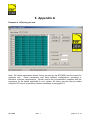
1
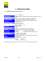
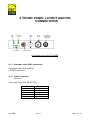
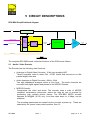
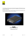
The information contained in this manual remains the property of RF Central and may not be used, disclosed or reproduced in any other form whatsoever without the prior written permission of RF Central. RF Central reserves the right to alter the equipment and specification appertaining to the equipment described in this manual without notification. RFX-BRK OPERATORS MANUAL Copyright 2006 RF Central RFX-BRK Issue 1 page 1 of 19 CONTENTS 1 2 3 4 5 6 7 8 9 GENERAL SAFETY INFORMATION............................................................................3 1.1 Health & Safety......................................................................................................4 1.2 Maximum RF Power Density Limits.......................................................................5 1.3 Issue Status...........................................................................................................5 INTRODUCTION ..........................................................................................................6 SPECIFICATIONS........................................................................................................7 3.1 RFX-BRK Transmitter Specifications.....................................................................7 FRONT PANEL LAYOUT AND PIN CONNECTIONS ..................................................8 4.1.1 Analogue video (BNC connector) ...................................................................8 4.1.2 Audio Connector.............................................................................................8 4.1.3 Power and Data Connector ............................................................................9 4.1.4 RF O/P ...........................................................................................................9 CIRCUIT DESCRIPTIONS .........................................................................................10 5.1 Audio / Video Encoder.........................................................................................10 5.2 COFDM Modulator ..............................................................................................11 5.3 Power Amplifier ...................................................................................................11 5.4 Maintenance of the RFX-BRK .............................................................................11 CONFIGURING THE TRANSMITTER........................................................................12 6.1 Status Monitoring.................................................................................................12 6.2 Preset configuration rotary selector switch ..........................................................12 6.3 Remote set-up of the 16 preset configurations. ...................................................13 PREPARING FOR OPERATION ................................................................................16 7.1 The RFX-BRK Transmitter ..................................................................................16 7.1.1 Antennas ......................................................................................................16 7.1.2 Transmitter checks .......................................................................................16 7.2 The Receiving Equipment ...................................................................................16 7.3 Transmitter / Receiver tests.................................................................................17 Appendix A .................................................................................................................18 Example of 16 Factory pre-sets..................................................................................18 Appendix B .................................................................................................................19 RFX-BRK Issue 1 page 2 of 19 1 GENERAL SAFETY INFORMATION The information that follows, together with local site regulations, must be studied by personnel concerned with the operation or maintenance of the equipment, to ensure awareness of potential hazards. WARNING- RF Power Hazard : High levels of RF power are present in the unit. Exposure to RF or microwave power can cause burns and may be harmful to health. Switch off supplies before removing covers or disconnecting any RF cables, and before inspecting damaged cables or antennas. Avoid standing in front of high gain antennas (such as a dish) and never look into the open end of a waveguide or cable where RF power may be present. Users are strongly recommended to return any equipment that requires RF servicing to RF Central. WARNING- GaAs / BeO Hazard : Certain components inside the equipment contain Gallium Arsenide and Beryllium Oxide that are toxic substances. Whilst safe to handle under normal circumstances, individual components must not be cut, broken apart, incinerated or chemically processed. In the case of Beryllium Oxide, a white ceramic material, the principal hazard is from the dust or fumes which are carcinogenic if ingested, inhaled or entering damaged skin. Please consult your local authority before disposing of these components. CAUTION- Tantalum Capacitors : When subjected to reverse or excess forward voltage, ripple current or temperature these components may rupture and could potentially cause personal injury. CAUTION : This system contains MOS devices. Electro-Static Discharge (ESD) precautions should be employed to prevent accidental damage. RFX-BRK Issue 1 page 3 of 19 1.1 Health & Safety Exposure to Non Ionising (RF) Radiation/Safe Working Distances The safe working distance from a transmitting antenna may be calculated from the relationship: D= √ PT. GR 4π.w in which D = safe working distance (metres) PT = transmitter or combiner power output (watts) GR = antenna gain ratio = anti log (gain dBi ÷10) w = power density (watts/square metre) The RF power density value is determined by reference to safety guidelines for exposure of the human body to non-ionising radiation. It is important to note that the guidelines adopted differ throughout the world and are from time-to-time re-issued with revised guidelines. For RF Central use, a maximum power density limit of 1w/m² is to be applied when calculating minimum safe working distances. Appendix A refers. Important Note: It must be remembered that any transmitting equipment radiating power at frequencies of 100 KHz and higher, has the potential to produce thermal and athermal effects upon the human body. To be safe: a) Operators should not stand or walk in front of any antenna, nor should they allow anyone else to do so. b) Operators should not operate any RF transmitter or power amplifier with any of its covers removed, nor should they allow anyone else to do so. Worked examples Antenna Type OMNI HELIX PARABOLIC DISH Gain (dBi) 4 20 35 Gain Ratio 2.5 100 3,162 Transmitter Power 2W 4W 1 1 4 5.6 22.5 32 10W 1.5 9 50 30W 2.5 15.5 87 MINIMUM SAFE DISTANCE (METRES) RFX-BRK Issue 1 page 4 of 19 1.2 Maximum RF Power Density Limits The RF Radiation Power Density limit figure recommended by RF Central is based upon guideline levels published in: a. IEEE standard C95.1 1999 - IEEE Standard for Safety Levels with respect to Human Exposure to Radio Frequency Electromagnetic Fields, 3 KHz to 300 GHz. b. Guidelines for Limiting Exposure to Time-varying Electric, Magnetic & Electromagnetic Fields (up to 300 GHz) published in 1998 by the Secretariat of the International Commission on Non-Ionising Radiation Protection (ICNIRP). Both documents define guideline RF power density limits for "Controlled" and "Uncontrolled" environments. An uncontrolled environment is defined as one in which the person subjected to the RF radiation may be unaware of and has no control over the radiation energy received. The uncontrolled environment conditions can arise, even in the best regulated operations and for this reason the limits defined for the uncontrolled environment have been assumed for the RF Central recommended limit. Documents a) and b) also show the RF power density guidelines to be frequency dependent. Different power density / frequency characteristics are presented in the two documents. To avoid complexity and to avoid areas of uncertainty, RF Central recommends the use of a single power density limit across the frequency range 100 KHz to 300 GHz. The 1w/m² power density limit we recommend satisfies the most stringent of the guidelines published to date. Footnote: The IICNIRP document may be freely downloaded from the internet at www.icnirp.de/emfgdl (PDF file). 1.3 Issue Status Issue Issue 1 RFX-BRK Date 6 Jan. 2006 th Changes first issue Issue 1 page 5 of 19 2 INTRODUCTION The RF Central RFX-BRK ultra compact transmitter is designed for all applications, both indoor and outdoor, in which a very small light weight transmitter is essential to the operation. The unit features a comprehensive range COFDM modulation formats, QPSK 16QAM, 64QAM. Set-up of the unit – e.g. RF channel, MPEG coding profile, COFDM modulation format – is via the 16 position rotary switch on the front panel. PC software is supplied to allow RF channel and COFDM modulation parameters to be pre-programmed for each of the 16 preset positions. The transmitter is a single miniature unit that contains a MPEG2 video encoder, audio encoder, COFDM modulator, RF power amplifier and power supplies, all of which are mounted on a single printed circuit broad inside the case. The transmitter is designed to accept analogue video (NTSC or PAL) and 2 analogue audios at line level. Powering is +9 to 18 VDC. The unit can be used with a variety of RF Central antennas: ”F1 patch”, a small low profile antenna which matches the ultra compact features of the transmitter Omni antennas are typically used for ground based fixed and mobile operations, or helicopter air to ground Low profile antennas are used for up-linking ground to air, or on-board linking Helix antennas offer increased gain and directivity Fan-beam antennas offer increased gain and 90 degree sector coverage. GPS steered antenna, for helicopter air to ground Parabolic antennas offer the highest gain, and longest operational range At the receive site a range of RF Central digital receivers may be used. Please consult the separate RF Central manual for information detailing the operation of receivers. RFX-BRK Issue 1 page 6 of 19 3 SPECIFICATIONS 3.1 RFX-BRK Transmitter Specifications Frequency Band Tuning Range Frequency Selection Transmit Power Transmit Antenna Modulation Modulation Modes Data Rate Bandwidth Encoding Options Latency Video Input Audio Input Remote set-up Power Requirement Size Weight Environmental 1.99 – 2.50GHz band 500MHz standard bandwidth. Wider bandwidths available to special order Up to 16 pre-set channels, user editable in 0.5MHz steps 100mW or higher, subject to customer requirements Interfaces with the complete range of RF Central antennas COFDM DVB-T 2k QPSK, 16QAM, 64QAM FEC: 1/2 2/3 3/4 5/6 7/8 Guard interval: 1/32 1/16 1/8 1/4 4.98 to 24 Mbit/s 8MHz MPEG 2: 4:2:0 high quality video (DVB standard) Selectable to less than 7 frames minimum, Tx to Rx Analogue: Composite video (PAL/NTSC) Analogue: 1 x stereo/ 2 x mono inputs, line level via USB port and PC software 9 – 18VDC (10W at 12VDC) 148mm (L) x 99mm (W) x 20mm (H) (excluding connectors) 400g (14.12oz) Temperature: -4° to +122°F Altitude: 14,500 ft. Humidity: 95% long term Specifications may alter at the discretion of RF Central or to meet customer specific requirements. RFX-BRK Issue 1 page 7 of 19 4 FRONT PANEL LAYOUT AND PIN CONNECTIONS PA LED DC Power LED RF output Audio inputs Video input Combined DC input and USB port Config select Front panel view of the RFX-BRK 4.1.1 Analogue video (BNC connector) Composite video, PAL or NTSC. 75Ω BNC connector 4.1.2 Audio Connector Line level 5 Pin Lemo Plug ECG.1B.305.CLN Pin 1 2 3 4 5 RFX-BRK Function 0V (Screen) Ch1 + Ch1 Ch2 + Ch2 - Issue 1 page 8 of 19 4.1.3 Power and Data Connector Dual purpose connector: DC input USB data port Connector Type: 4 pin LEMO connector EGG.OB.304.CLN Input range: 10V to 18V DC. Pin 1 2 3 4 Function +12V 0V Cont. RXD Cont. TXD Note: operators are recommended to use the USB Data cable supplied by RF Central to connect from the RFX-BRK to the PC. 4.1.4 RF O/P Connector Type: RFX-BRK 50Ω SMA Issue 1 page 9 of 19 5 CIRCUIT DESCRIPTIONS RFX-BRK Simplified block diagram DC in Power supply Encoder Composite video Video/ audio processing Analogue audio 1, 2 I2S Transport stream MPEG coder COFDM modulator RF Power amplifier TX RF out Power supply USB port CDT TX Simplified block diagram The complete RFX-BRK board; individual functions of the PCB are as follows: 5.1 Audio / Video Encoder The Encoder has the following main functions : • Analogue to Digital Video Converter, 10 bit over sampling ADC Takes Composite Video in either PAL / NTSC format and converts to an 8bit parallel digital video bus. • Audio Analogue to Digital Converter, 48kHz, 24 bit Two high impedance analogue inputs at Line level. The audio channels are converted into digital signals and passed to the MPEG2 Encoder. • MPEG2 Encoder Compresses the video and audio. The encoder uses a suite of MPEG2 compliant compression techniques, where the data bit rate is reduced by processing over multiple picture frames. The RFX-BRK MPEG encoder operates at MP@ML (4.2.0) only. Low data rates down to 4 Mbps, can be achieved. The encoding parameters are loaded into the encoder at power up. These are selected by the ‘preset’ rotary switch position. See 6.2 RFX-BRK Issue 1 page 10 of 19 • DC Power Supplies DC/DC converters are used to generate the various supplies from the incoming 9-18V battery supply. These include 2.5, 3.3V, 5V, 8V and 1.2V. 5.2 COFDM Modulator The normal scheme of COFDM modulation adopted by RF Central for the RFX-BRK is 2k carriers with 8MHz RF band-width. The COFDM modulator has been designed to take its input from the MPEG2 encoder. This Transport stream is then modulated directly to the output frequency band (e.g. 2GHz). This method reduces the occurrence of inter-modulated harmonic frequencies, requires less upconvertors, and results in a smaller size for the RFX-BRK transmitter. The modulator is automatically configured to match the data rate of the MPEG2 Encoder as defined by the selected parameter set. See paragraph 6.2 5.3 Power Amplifier The function of the power amplifier is to amplify the signal from the COFDM modulator to a suitable level for transmission via the SMA-type connector into the antenna. The amplifier is required to be highly linear to accommodate the multiple carrier signal formats employed for digital system operation, with very low distortion (low inter-modulation between carriers). The nominal output power is +20dBm (100mW) (band specific) The status of the PA is provided by an LED to monitor RF output level (blue), see paragraph 6.1 5.4 Maintenance of the RFX-BRK To ensure good RF practice, when power is applied to the RFX-BRK, always make sure that there is a suitable load or antenna connected to the RF output. There are no field replaceable parts on the unit PCB. If a fault occurs with the board, please contact RF Central for technical assistance. RFX-BRK Issue 1 page 11 of 19 6 CONFIGURING THE TRANSMITTER 6.1 Status Monitoring There are two status LEDs on the front panel of the unit Power LED Green = DC power is applied to the unit. Flashing = normal operation PA LED Blue = the PA is on. 6.2 Preset configuration rotary selector switch The front panel rotary selector switch allows selection of the 16 preset configurations which are loaded into the unit. Each RFX-BRK transmitter is pre-programmed with factory defaults for each of the 16 preset positions. The standard defaults are shown in appendix A (paragraph 8). These can be edited and updated at any time using RF Central proprietary software through a USB port and PC or Lap Top computer. The following operating parameters may be set: RF channel (TX operating frequency in 0.5MHz steps) MPEG encoder bit rate COFDM modulator operating mode QPSK, 16QAM, 64QAM Viterbi FEC rate Guard interval RFX-BRK Issue 1 page 12 of 19 6.3 Remote set-up of the 16 preset configurations. PC software is supplied to allow each of the 16 preset rotary switch positions to be preprogrammed according the operator's desired RF channel and COFDM modulation parameters. The RFX-BRK transmitter is connected to the PC via the combined DC/USB Lemo connector. When connecting to the PC the user is recommended to use the USB data cable supplied by RF Central which is fitted with the correct Lemo connector - see 4.1.3. The required sequence when re-programming the profile information into the RFX-BRK transmitter is as follows: • Connect the power/data Lemo connector into the RFX-BRK. • Switch on the power to the transmitter. • Connect the USB lead to the PC. • Start the programming software by double clicking on the file MiniDigiTXConfig.exe. • If required change the software for the correct comm. port by selecting the tab Comms Settings. RFX-BRK Issue 1 page 13 of 19 To re-configure the 16 sets of profile parameters: • Select the tab Mini TX Config. • To open a profile already stored on the PC click File/Load Profiles , and choose/open the required .pf file in the normal Windows manner • Similarly, to open the file already stored in the RFX-BRK TX click TX unit/Get Profiles RFX-BRK Issue 1 page 14 of 19 To modify a profile double click the required profile number, this opens the Profile Edit Form • Modify the frequency by typing into the box, and change the modulation, code rate and guard interval from the drop down list. • Store each profile as it is updated. • repeat for other profiles as required • on completion select the Close button • To save the new profile to the computer click File/Save Profiles • To save the new profile to the RFX-BRK transmitter click TX Unit/Set Profiles RFX-BRK Issue 1 page 15 of 19 7 PREPARING FOR OPERATION EQUIPMENT PREPARATION Before leaving the equipment base to undertake an operation it is recommended that the following equipment checks be made. 7.1 The RFX-BRK Transmitter 7.1.1 Antennas The unit can be used with a variety of RF Central antennas: ”F1 patch”, a small low profile antenna which matches the ultra compact features of the transmitter Omni antennas are typically used for ground based fixed and mobile operations, or helicopter air to ground Low profile antennas are used for uplinking ground to air, or on-board linking Helix antennas offer increased gain and directivity Fan-beam antennas offer increased gain and 90 degree sector coverage. GPS steered antenna, for helicopter air to ground Parabolic antennas offer the highest gain, and longest operational range Full details are given in the RF Central Antennas data sheet 7.1.2 Transmitter checks The transmitter may be powered from an external AC/DC PSU, or by batteries. Check that any batteries to be used are fully charged and that an emergency spare battery is available and fully charged. Confirm that the correct pre-set RF channel and modulator operating mode is selected by the rotary switch on the front panel. 7.2 The Receiving Equipment The RFX-BRK mini transmitter may be used with a variety of RF Central digital receivers. Full details on the operation of the receiver are given in the associated manuals. When used with the RFX-BRK transmitter, the receiving equipment produces two audio channels, analogue and AES3 digital, together with SDI and composite video monitoring port. The RFX-RMR receiver also has an ASI output. RFX-BRK Issue 1 page 16 of 19 Check that audio, video, triax, AC and DC cables of sufficient total length and are in good condition. If extension cables are necessary ensure that the connectors are compatible and of good quality to avoid problems at site. Check that the receiving antenna/Receiver interfaces are clean and free from dust and other unwanted materials. If tripods are to be used to mount the equipment, make sure that some means of securing the tripod or of weighting it down is provided. Gusty wind conditions may put installations at risk, particularly when parabolic antenna dishes are to be used. Make sure that all batteries to be used are fully charged and, whenever possible, provide a spare with cable to connect it to the receiver. Check that the receiver channel frequencies are compatible with those of the RFX-BRK Transmitter. The receiver is labelled with channel number and frequency information. 7.3 Transmitter / Receiver tests Whenever practical, set up the system and trial it before leaving for site to ensure that all components of the system are working. Checking at base, where adjustments and corrective actions can be made, will pay off when setting up at site. RFX-BRK Issue 1 page 17 of 19 8 Appendix A Example of 16 Factory pre-sets Note: The above parameters denote factory pre-sets for the RFX-BRK and are issued for guidance only. Some transmitters may have different configurations according to individual customer requirements. Please consult the documentation supplied with the equipment for the details applicable to your system. All factory pre-sets may be edited using the RF Central proprietary software mentioned in paragraph 6.3 RFX-BRK Issue 1 page 18 of 19 9 Appendix B Table of DVB-T non-hierarchical bit rates Modulation Code rate QPSK 1/2 2/3 3/4 5/6 7/8 16-QAM 1/2 2/3 3/4 5/6 7/8 1/32 12.1 16.1 18.1 20.1 21.1 1/16 11.7 15.6 17.6 19.5 20.5 1/8 11.1 14.7 16.6 18.4 19.4 1/4 9.95 13.3 14.9 16.6 17.4 1/2 2/3 3/4 5/6 7/8 1/32 18.1 24.1 27.1 30.2 31.7 1/16 17.6 23.4 26.3 29.3 30.7 1/8 16.6 22.1 24.9 27.6 29.0 1/4 14.9 19.9 22.4 24.9 26.1 64-QAM RFX-BRK Bit rate (Mbit/s) at each guard interval (symbol fraction) 1/32 1/16 1/8 1/4 6.03 5.85 5.53 4.98 8.04 7.81 7.37 6.64 9.05 8.78 8.29 7.46 10.1 9.76 9.22 8.29 10.6 10.2 9.68 8.71 Issue 1 page 19 of 19