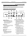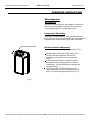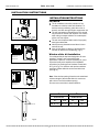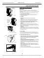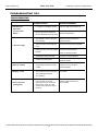
1
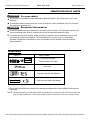
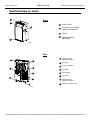
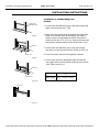
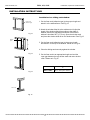
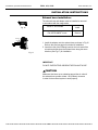
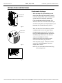
TAB LE AIR CO ND ITIO NER
INSTALLATION, OPERATION
& MAINTENANCE MANUAL
Portable Room Air Conditioner
PS-81A
PS-101A
PS-121A
French version of this manual is available on our website
Heat Controller, Inc. • 1900 Wellworth Ave. • Jackson, MI 49203 • (517)787-2100 • www.heatcontroller.com
PS-81, 101, 121A
Installation, Operation & Maintenance
Heat Controller, Inc.
TABLE OF CONTENTS
SAFETYPRECAUTIONS
PRECAUTIONS
SAFETY
Safety
.......................................................................................................................................3
Safetyrules
rules.......................................................................................................................3
Operating
conditions
.........................................................................................................................3
Operating conditions.........................................................................................................3
Electrical information..........................................................................................................................4
Electrical information.........................................................................................................4
IDENTIFICATION
IDENTIFICATIONOF
OFPARTS
PARTS
Accessories .......................................................................................................................................4
Accessories.......................................................................................................................4
Identification of parts..........................................................................................................................5
Identification of parts.........................................................................................................5
AIR
AIR CONDITIONER
CONDITIONERFEATURES
FEATURES
Electronic control operating instructions ...........................................................................................6
Electronic control operating instructions............................................................................6
OPERATING
OPERATINGINSTRUCTIONS
INSTRUCTIONS
Operating instructions .......................................................................................................................8
Operating instructions.......................................................................................................8
INSTALLATION
INSTALLATIONINSTRUCTIONS
INSTRUCTIONS
Location
............................................................................................................................................9
Location.............................................................................................................................9
Window slider kit installation ............................................................................................................9
Windowhose
slider
kit installation.............................................................................................9
Exhaust
installation
................................................................................................................12
Condensate
drainage
......................................................................................................................13
Exhaust hose
installation.
................................................................................................12
Condensate drainage......................................................................................................13
CARE AND MAINTENANCE
CARE
MAINTENANCE
Care
and AND
maintenance
....................................................................................................................14
Care and maintenance....................................................................................................14
TROUBLESHOOTING TIPS
TROUBLESHOOTING
TIPS
Trouble
shooting ..............................................................................................................................15
Trouble shooting..............................................................................................................15
2
PS-81, 101, 121A
Heat Controller, Inc.
Installation, Operation & Maintenance
SAFETY PRECAUTIONS
Safety rules
W
To prevent injury to the user or other people and property damage, the following instructions must be
followed. Incorrect operation due to ignoring the instructions may cause harm or damage.
!
Always do this
Never do this
Do not operate your air conditioner in a damp/
humid room such as a bathroom or laundry room.
Do not touch the unit with wet or damp hands or
to avoid electrical shock.
Do not remove any cover panels.
Never use this appliance if it is not working properly,
or if it has been dropped or damaged.
Never use the plug to start and stop the unit. Always
use the switch on the control panel.
Do not cover or obstruct the inlet or outlet grilles.
Do not use hazardous chemicals to clean or allow
them to come into contact with the unit.
Do not use the unit in the presence of inflammable
substances or vapors such as alcohol, insecticides,
gasoline, etc.
Do not use this product for functions other than
those described in this instruction manual.
Your air conditioner should be used in such a way
that it is protected from moisture. e.g. condensation,
splashed water, etc. Do not place or store your air
conditioner where it can fall or be pulled into water
or any other liquid. Unplug immediately if water
enters unit.
Always transport use and store your air conditioner
in a vertical, upright position on a stable, level
surface.
Turn off the product when not in use.
Always contact a qualified servicer to make
repairs. If the supply cord is damaged it must be
repaired by an authorized servicer.
Keep a clearance of at least 1 ft. (30cm) around
the unit, away from walls, furniture and curtains.
If the air conditioner is knocked over during use,
turn off the unit and unplug from the main power
supply immediately.
Do
ap
To
an
W
Be
on
To
in
gro
pro
Acc
Save Energy
Use the unit in the recommended room size - see carton.
Locate the unit where furniture or other objects cannot obstruct the air flow.
Keep blinds/curtains closed during the sunniest part of the day.
Keep the filters clean.
Keep doors and windows closed to keep cool air in and warm air out.
Operating conditions
The air conditioner must be operated within the temperature range indicated below:
MODE
ROOM TEMPERATURE
COOL
62-95 F (17-35OC)
DRY
55-95 F (13-35 C)
O
O
Ch
the
NOT
O
Suggested tools for window kit installation
1. Screwdriver(medium size Phillips)
2. Tape measure or ruler
3. Knife or scissors
4. Saw(In the event that the window kit needs to be cut down in size because
the window is too narrow for direct installation)
3
Installation, Operation & Maintenance
PS-81, 101, 121A
Heat Controller, Inc.
IDENTIFICATION OF PARTS
WARNING
For your safety
Do not store or use gasoline or other flammable substances/vapors in the vicinity of this or any other
appliance.
To avoid fire hazard or electric shock, do not use an extension cord or an adaptor plug. Do not remove
any prong from the power cord.
WARNING
Electrical Infor mation
Be sure the electrical service is adequate for the model you have chosen. This information can be found
on the name/rating plate, which is located on the side of the cabinet and behind the grille.
To minimize shock and fire hazards, proper grounding is important. Your air conditioner must be used
in a properly grounded wall receptacle. If the wall receptacle you intend to use is not adequately
grounded or protected by a time delay fuse or circuit breaker, have a qualified electrician install the
proper receptacle.
Accessories
PARTS :
PARTS NAME :
Exhaust hose and Apaptor
Window Slider Kit and bolt
Foam seal
TEMP
FAN
HIGH
MED
LOW
TIMER ON
TIMER OFF
ON/OFF FAN SPEED
ECONOMY
RESET LOCK
FOLLOW
LED
ME
DISPLAY TURBO
SET TEMPERATURE( C)
AUTO
COOL
DRY
HEAT
ION
SWING
MODE
Remote Controller and Batteries
Drain hose and drain hose adaptor
Check all the accessories are included in the package and please refer to the installation instructions for
their usage.
NOTE: All the illustrations in this manual are for explanation purposes only. Your air conditioner
may be slightly different. The actual shape of parts, accessories, unit, etc. shall prevail.
4
PS-81, 101, 121A
Heat Controller, Inc.
Installation, Operation & Maintenance
IDENTIFICATION OF PARTS
1
Front
2
4
1
Control Panel
2
Horizontal Louver Blade
(swings automatically)
3
Casters
4
Carrying Handles
(both sides)
3
N
C
O
Fig.1
Rear
6
7
9
10
Upper Air Filter
(Behind the grille)
7
Air Outlet
8
Power cord outlet
9
Air intake
10 Drain Outlet
11
8
6
12
13
Fig.2
11
Air intake
12
Lower Air Filter
(Behind the grille)
13
Bottom tray drain outlet
5
5
PS-81, 101, 121A
Installation, Operation & Maintenance
Heat Controller, Inc.
AIR CONDITIONER FEATURES
ELECTRONIC CONTROL OPERATING INSTRUCTIONS
Before you begin, thoroughly familiarize yourself with the functions control panel and remote
controller.
The unit can be controlled by the unit control panel alone or with the remote controller .
NOTE: This manual does not include Remote Controller Operations, see the <<Remote
Controller Instruction>> packed with the unit for details.
OPERATION PANEL OF THE AIR CONDITIONER
8
6
7
6
Remote signal receptor
SWING
AUTO
HI
COOL
DRY
F
TIMER ON
MODE
MED
SLEEP
TIMER OFF
FAN
1
C
3
2
4
FAN
LOW
5
Fig.3
6
1 MODE select button
Selects the appropriate operating mode.
Each time you press the button, a mode
is selected in a sequence that goes from
AUTO, COOL, DRY, and FAN. The mode
indicator light illuminates under the
selected mode settings Fig.3.
UP(
) and DOWN( ) button
Used to adjust (increasing/decreasing)
O
O
temperature settings(2 F/1 C increments)
O
O
in a range of (62 F)17 C to (88OF)30OC or
the TIMER setting in a range of 0~24hrs.
NOTE: The control is capable of displaying
temperature in degrees Fahrenheit or degrees
Celsius. To convert from one to the other, press
and hold the Up and Down buttons at the same
time, for 3 seconds.
2 TIMER button
Used to initiate the AUTO ON start time and
AUTO OFF stop time program, in conjunction
with the
and
buttons.
7
3 POWER button
Power switch on/off.
4 SLEEP button
Used to initiate the SLEEP operation.
5 FAN button
Controls the fan speed. Each time the fan button
is pressed, a different fan speed is selected in a
sequence as follows: LOW, MED, HI and AUTO.
When AUTO mode is selected, all of the fan
indicator lights turn off.
6
LED Display
Shows the set temperature in " OC " or
O
" F" and the Auto-timer settings.
While in DRY or FAN modes, it displays
the room temperature.
Error codes and protection code:
E1- Room temperature sensor errorUnplug the unit and plug it back in.
If error repeats, call for service.
E2- Evaporator temperature sensor errorUnplug the unit and plug it back in.
If error repeats, call for service.
E4- Display panel communication errorUnplug the unit and plug it back in.
If error repeats, call for service.
P1- Bottom tray is full - Connect the
drain hose and drain the collected
water away. If error repeats, call
for service.
Heat Controller, Inc.
PS-81, 101, 121A
Installation, Operation & Maintenance
OPERATING INSTRUCTIONS
8 SWING button
Used to initiate the automatic swing function.
When the swing mode is on, press the swing
button to stop the lover at the desired angle.
Pressing and holding the button can restart
the auto swing function.
FAN operation
- Press the "MODE" button until the
"FAN " indicator light comes on.
- Press the "FAN SPEED" button to
select the desired fan speed. The
temperature cannot be adjusted.
- Do not connect the duct to window.
Operating Instructions
TIMER operation
COOL operation
- Press the "MODE" button until the "COOL"
indicator light comes on.
- Press the ADJUST buttons “p” or “q” to
select the desired room temperature.
- Press the "FAN SPEED" button to select the
desired fan speed.
-
-
DRY operation
- Press the "MODE" button until the "DRY" indicator
light comes on.
- Under this mode, you cannot change the fan speed or
adjust the temperature. The fan motor operates at
LOW speed automatically.
- Keep windows and doors closed for the best
dehumidifying effect.
- Do not connect the duct to window.
AUTO operation
-
-
-
-
-
When you set the air conditioner in AUTO
mode, it will automatically select cooling,
or fan only operation depending on what
temperature you have selected in relation
to the actual room temperature.
The air conditioner will control room
temperature automatically around the
temperature point set by you.
Under AUTO mode, you can not
change the fan speed.
-
When the unit is on, press the
Timer button, the TIMER OFF
indicator light illuminates. It indicates that the Auto Stop program is
initiated.
When the unit is off, press the
Timer button, the TIMER ON indicator light illuminates. It indicates that
the Auto Start program is initiated.
Press or hold the UP or DOWN
buttons to change the time by
0.5 hour increments, up to 10 hours,
then at 1 hour increments up to 24
hours. The control will count down
the time remaining until start.
The selected time will register in 5
second and the system will automatically revert back to display the
previous temperature setting.
Turning the unit ON or OFF at any
time or adjusting the timer setting
to 0.0 will cancel the Auto Start/
Stop timed program.
When an error or malfunction (E1 or E2)
occurs, the Auto Start/Stop timed
program will also be cancelled.
SLEEP operation
By pressing the sleep button, the selected
temperature will increase(cooling) or decrease
O
O
(heating) by 2 F/1 C over 30 minutes. The
temperature will then increase(cooling) by another
2OF/1OC after an additional 30 minutes.
This new temperature will be maintained for
7 hours before it returns to the originally selected
temperature. This ends the Sleep mode
and the unit will continue to operate as
originally programmed.
NOTE: This feature is unavailable under
FAN or DRY mode.
7
Installation, Operation & Maintenance
PS-81, 101, 121A
Heat Controller, Inc.
OPERATING INSTRUCTIONS
Other features
Auto-Restart
If there is a loss of power, once power is restored,
the unit will automatically reset in the last mode
it was operating prior to the power failure.
Compressor Time Delay
After the unit has stopped, it can not be restarted
for 3 minutes. This is to protect the unit’s compressor.
Operation will automatically start after 3 minutes.
Swing automatically
Air flow direction adjustment
The louver can be adjusted automatically. Fig. 4.
When power is ON, the louver opens fully.
Use the SWING button on the remote
controller to stop the louver at a desired
angle.
If the louver is placed in a position which
would affect the cooling process of the air
conditioner, it will automatically change the
swing direction.
If you press the SWING button for more
than 2 seconds, the auto swing feature will
stop. The louver swings as shown in Fig. 4.
2)
Fig.4
se
nother
ected
8
PS-81, 101, 121A
Heat Controller, Inc.
Installation, Operation & Maintenance
INSTALLATION INSTRUCTIONS
INSTALLATION INSTRUCTIONS
Location
B
The air conditioner should be placed on a firm
foundation to minimize noise and virbration. For
safe and secure positioning, place the unit on a
smooth, level floor strong enough to support the unit.
The unit has casters to aid placement, but it should
only be rolled on smooth, flat surfaces. Use caution
when rolling on carpet surfaces. Do not attempt to
roll the unit over objects.
The unit must be placed within reach of a properly
rated grounded socket.
Never place any obstacles around the air inlet or
outlet of the unit.
Allow 1ft.-3ft.(30cm to 100cm) of space from the
wall with for efficient air-conditioning. (Fig.5)
A
Fig.5
A:1ft.-3ft.(30cm-100cm) B: 1ft.( 30cm)
Horizontal
window
Window slider kit Installation
Window Slider Kit
Minimum: A
Maximum: B
Fig.6
Horizontal
window
Your window slider kit has been designed to fit most
standard "Vertical" and "horizontal"window
applications. However, it may be necessary for you to
improvise/modify some aspects of the installation
procedures for certain types of windows. Please refer
to Fig. 6 & Fig.7 for minimum and maximum window
openings. Window slider kit can be fixed with a bolt
(see Fig.7a).
Note: If the window opening is less than the mentioned
minimum length of the window slider kit, cut the one
with a hole in it to fit the window opening.
Do never cut out the hole in window slider kit.
Window Slider Kit
Minimum: A
Maximum: B
Fig.7
A
Minimum
cm
in.
26-9/16 67.5
bolt
Window slider kit
Fig.7a
9
B
Maximum
cm
in.
48-1/2 123
PS-81, 101, 121A
Installation, Operation & Maintenance
INSTALLATION INSTRUCTIONS
Installation in a double-hung sash
window
Foam seal A
(adhesive type)
or
a
e unit.
ould
ution
t to
Fig.8
erly
or
he
Heat Controller, Inc.
1. Cut the foam seal (adhesive type) to the proper length and
attach it to the window stool. Fig.8
2. Attach the window slider kit to the window stool. Adjust the
length of the window slider kit according to the width of
window, shorten the adjustable window kit if the width of
window is less than 26.5” (67.5 cm). Open the window sash
and place the window slider kit on the window stool. Fig.9
Window kit
3. Cut the foam seal (adhesive type) to the proper length
and attach it on the top of the window. Shown as in Fig.10
C
4. Close the window sash securely against the window.
Window stool
ost
Fig.9
5. Cut the foam seal to an appropriate length and seal the
open gap between the top window sash and outer window
sash. Shown as in Fig.11.
u to
efer
ow
lt
Window kit
C
Window stool
ioned
ne
Min-max.
Fig.10
Foam seal
Fig.11
10
26.5”~ 48.5” (67.5-123 cm)
PS-81, 101, 121A
Heat Controller, Inc.
Installation, Operation & Maintenance
INSTALLATION INSTRUCTIONS
Installation in a sliding sash window
Foam seal A
(adhesive type)
Fig.12
1. Cut the foam seal (adhesive type) to the proper length and
attach it to the window frame. See Fig.12.
2. Attach the window slider kit to the window stool. Adjust the
length of the window slider kit according to the width of
window, shorten the adjustable window kit if the width of
window is less than 26.5” (67.5 cm). Open the window sash
and place the window slider kit on the window stool. See Fig.13.
Window
panel
C
3. Cut the foam seal (adhesive type) to the proper length
and attach it on the top of the window. Shown as in Fig.14.
4. Close the sliding sash securely against the window.
Fig.13
5. Cut the foam seal to an appropriate length and seal the
open gap between the top window sash and outer window
sash. Shown as in Fig.15.
C
Fig.14
Min-max.
Foam seal
Fig.15
11
26.5”~ 48.5” (67.5-123 cm)
h
g.13.
Installation, Operation & Maintenance
PS-81, 101, 121A
Heat Controller, Inc.
INSTALLATION INSTRUCTIONS
Exhaust hose installation:
The exhaust hose and adaptor must be installed or removed
in accordance with the usage mode.
COOL or AUTO mode
Fig.16
FAN, OR DEHUMIDIFY mode
Install
Remove
Hole seat
Hook
Fig.17
1. Install the adaptor onto the exhaust hose as shown in Fig.16.
Refer to the previous pages for window kit installation.
2. Insert the hook of the Exhaust hose into the hole seat of the
air outlet and slide down the Exhaust hose along the arrow
direction (See Fig.17) for installation.
IMPORTANT:
DO NOT OVER EXTEND OR BEND THE EXHAUST HOSE
CAUTION:
Make sure that there are no obstacles around the air outlet of
the exhaust hose provide at least 1.5ft.(500mm) clearance
in order for the exhaust system to work properly.
12
PS-81, 101, 121A
Heat Controller, Inc.
Installation, Operation & Maintenance
INSTALLATION INSTRUCTIONS
Condensate drainage:
Remove the
drain plug
While operating in Dry (dehumidifying) mode,
remove the drain plug from the back of the unit,
install the drain connector (5/8” universal female
mender) with 3/4” hose(locally purchased).
For the models without drain connector, just
attach the drain hose to the hole. Place the open
end of the hose directly over the drain area in your
basement floor. Please refer to Fig.18 & 19.
Fig.18
-
R
s
t
i
d
When the water level of the bottom tray reaches
a predetermined level, the unit beeps 8 times,
Continuous
drain hose
the digital display area shows "P1". At this time
the air conditioning/dehumidification process will
immediately stop. However, the fan motor will
continue to operate(this is normal).
Carefully move the unit near a drain location,
remove the bottom drain plug and let the
water drain away (Fig.20). Restart the machine
until the "P1" symbol disappears. If the error
Fig.19
repeats, call for service.
NOTE: Be sure to reinstall the bottom drain plug
before using the unit.
Band
Fig.20
13
13
PS-81, 101, 121A
Installation, Operation & Maintenance
Heat Controller, Inc.
CARE AND MAINTENANCE
Air filter
(slide out)
ode,
e unit,
female
).
ust
Fig.21
he open
ea in your
CARE AND MAINTENANCE
IMPORTANT:
1) Be sure to unplug the unit before cleaning or servicing.
2) Do not use gasoline, paint thinner or other chemicals to clean
the unit.
3) Do not wash the unit directly under a tap or using a hose.
It may cause electrical danger.
4) If the power cord is damaged, it should be repaired by
an authorized servicer.
1. Air filter
19.
Remove the
screw and
take the air
inlet grille
down
aches
es,
time
-
ss will
Fig.22
will
-
on,
chine
or
Remove the air filter
out from the grille
n plug
Fig.23
Power cord
Band
Clean the air filter at least once every two weeks.
Removal
This unit has two filters. Grasp the upper filter tab(Fig.21),
,,
,,
pull the filter out then up . Remove the lower filter by
,,
,,
loosening the screw, taking down the air inlet grille, then
removing the air filter as shown in Fig.22 & 23.
Cleaning
Wash the air filter by immersing it gently in warm water
O
O
(about 104 F/40 C) with a neutral detergent. Rinse the filter
and dry it in a shady place.
Installation
Insert the upper air filter from upward after cleaning, attach
the lower air filter on the air inlet grille, then reinstall the grille
by using the screw.
2. Unit cabinet
- Use a lint-free damp cloth with neutral detergent to clean
the unit enclosure. Finished by drying with a dry clean cloth.
3. Unit storage when not in use
-
Fig.24
-
Remove the rubber plug at the back of the unit and attach
a hose to the drain outlet. Place the open end of the hose
directly over the drain area in your basement floor
(See Fig.19 & 20).
Remove the plug from the bottom drain outlet, all the water
in the bottom tray will drain out (See Fig.23).
Keep the appliance running in FAN mode for half a day in
a warm room to dry the appliance inside and prevent mold
from forming.
Stop the appliance and unplug it, wrapped the cord and
bundle it with the buckle (Fig.24). Remove the batteries from
the remote controller.
Clean the air filter and reinstall it.
Unscrew the exhaust hose and pull out for uninstallation(Fig.25).
Fig.25
14
14
PS-81, 101, 121A
Heat Controller, Inc.
Installation, Operation & Maintenance
TROUBLESHOOTING TIPS
TROUBLESHOOTING
PROBLEM
POSSIBLE CAUSES
SUGGESTED REMEDIES
1. Unit does not
- P1 appears in the display window
Drain the water in the bottom tray.
Start when
Pressing on/off
Button
- Room temperature is lower than
the set temperature.(Cooling mode)
- The windows or doors in the room
are not closed.
2. Not cool enough
- There are heat sources inside the
Remove the heat sources if possible.
room.
blocked.
Connect the duct and make
sure it can function properly.
- Temperature setting is too high.
Decrease the set temperature.
- Air filter is blocked by dust.
Clean the air filter.
- The ground is not level or not flat
Place the unit on a flat, level
enough.
5. Gurgling sound
Make sure all the windows and
doors are closed.
- Exhaust air duct is not connected or
4. Noisy or vibration
Reset the temperature.
ground if possible.
- The sound comes from the flowing
It is normal.
of the refrigerant inside the
air-conditioner.
6. Power shut off at
Heating mode
- The automatic over heat
protection function. When the
temperature at the air outlet
O
O
exceed 70 C/158 F,th e de vice
will st op.
15
Switch on again after the unit
has cool down.
3-2013
04/2009