1
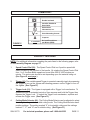
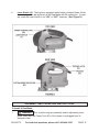
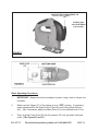
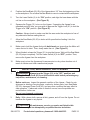
ORBITAL JIGSAW
LASER GUIDED
Model 92772
OPERATING INSTRUCTIONS
®
3491 Mission Oaks Blvd., Camarillo, CA 93011
Visit our Web site at: http://www.harborfreight.com
TO PREVENT SERIOUS INJURY,
READ AND UNDERSTAND ALL WARNINGS
AND INSTRUCTIONS BEFORE USE.
Copyright© 2005 by Harbor Freight Tools®. All rights reserved. No portion of this
manual or any artwork contained herein may be reproduced in any shape or form
without the express written consent of Harbor Freight Tools.
For technical questions, please call 1-800-444-3353.
PRODUCT SPECIFICATIONS
E194601
Item
Electrical Requirements
Speed Rating
Stroke Length
Description
120 VAC / 60 Hz / 5.5 Amps.
Power Switch Type: Lock On, Push Button.
Laser Switch Type: ON/OFF Push Button.
Laser Power: 2 “AAA” Batteries (not included).
Power Plug Type: 2 Prong, Polarized.
500 to 3,000 SPM (Strokes Per Minute).
11/16” With 4-Stage Orbital Action Settings.
Saw Blades
Variable Speed Control
Bevel Adjustment
Maximum Cutting Depth
Weight
Qty. 2 @ 4” x 10 TPI, Qty. 1 @ 3-1/4” x 25 TPI
6-Position Dial Switch.
0-45 Degrees Left / 0-45 Degrees Right.
2-1/2” @ 90° (Wood) / 1/4” @ 90° (Steel).
4.75 Pounds.
UNPACKING
When unpacking, check to make sure all the parts shown on the Parts List on page 16
are included. If any parts are missing or broken, please call Harbor Freight Tools at the
number shown on the cover of this manual as soon as possible.
SAVE THIS MANUAL
You will need this manual for the safety warnings and precautions, assembly, operating,
inspection, maintenance and cleaning procedures, parts list and assembly diagram.
Keep your invoice with this manual. Write the invoice number on the inside of the front
cover. Keep this manual and invoice in a safe and dry place for future reference.
GENERAL SAFETY RULES
WARNING!
READ AND UNDERSTAND ALL INSTRUCTIONS
Failure to follow all instructions listed below may result in
electric shock, fire, and/or serious injury.
SAVE THESE INSTRUCTIONS
WORK AREA
1.
Keep your work area clean and well lit. Cluttered benches and dark areas
invite accidents.
2.
Do not operate power tools in explosive atmospheres, such as in the
presence of flammable liquids, gases, or dust. Power tools create sparks
SKU 92772
For technical questions, please call 1-800-444-3353
PAGE 2
which may ignite the dust or fumes.
3.
Keep bystanders, children, and visitors away while operating a power tool.
Distractions can cause you to lose control. Protect others in the work area from
debris such as chips and sparks. Provide barriers or shields as needed.
ELECTRICAL SAFETY
1.
Grounded tools must be plugged into an outlet properly installed and
grounded in accordance with all codes and ordinances. Never remove the
grounding prong or modify the plug in any way. Do not use any adapter
plugs. Check with a qualified electrician if you are in doubt as to whether
the outlet is properly grounded. If the tools should electrically malfunction or
break down, grounding provides a low resistance path to carry electricity away
from the user.
2.
Double insulated tools are equipped with a polarized plug (one blade is
wider than the other). This plug will fit in a polarized outlet only one way. If
the plug does not fit fully in the outlet, reverse the plug. If it still does not
fit, contact a qualified electrician to install a polarized outlet. Do not
change the plug in any way. Double insulation
eliminates the need for the
three wire grounded power cord and grounded power supply system.
3.
Avoid body contact with grounded surfaces such as pipes, radiators,
ranges, and refrigerators. There is an increased risk of electric shock if your
body is grounded.
4.
Do not expose power tools to rain or wet conditions. Water entering a power
tool will increase the risk of electric shock.
5.
Do not abuse the Power Cord. Never use the Power Cord to carry the tools
or pull the Plug from an outlet. Keep the Power Cord away from heat, oil,
sharp edges, or moving parts. Replace damaged Power Cords immediately. Damaged Power Cords increase the risk of electric shock.
6.
When operating a power tool outside, use an outdoor extension cord
marked “W-A” or “W”. These extension cords are rated for outdoor use, and
reduce the risk of electric shock.
PERSONAL SAFETY
1.
Stay alert. Watch what you are doing, and use common sense when operating a power tool. Do not use a power tool while tired or under the influence of drugs, alcohol, or medication. A moment of inattention while operating power tools may result in serious personal injury.
SKU 92772
For technical questions, please call 1-800-444-3353
PAGE 3
2.
Dress properly. Do not wear loose clothing or jewelry. Contain long hair.
Keep your hair, clothing, and gloves away from moving parts. Loose
clothes, jewelry, or long hair can be caught in moving parts.
3.
Avoid accidental starting. Be sure the Power Switch is off before plugging
in. Carrying power tools with your finger on the Power Switch, or plugging in
power tools with the Power Switch on, invites accidents.
4.
Remove adjusting keys or wrenches before turning the power tool on. A
wrench or a key that is left attached to a rotating part of the power tool may result
in personal injury.
5.
Do not overreach. Keep proper footing and balance at all times. Proper
footing and balance enables better control of the power tool in unexpected
situations.
6.
Use safety equipment. Always wear eye ANSI approved safety impact eye
goggles. Dust mask, non-skid safety shoes, hard hat, or hearing protection
must be used for appropriate conditions.
TOOL USE AND CARE
1.
Use clamps (not included) or other practical ways to secure and support
the workpiece to a stable platform. Holding the work by hand or against your
body is unstable and may lead to loss of control.
2.
Do not force the tool. Use the correct tool for your application. The correct
tool will do the job better and safer at the rate for which it is designed.
3.
Do not use the power tool if the Power Switch does not turn it on or off.
Any tool that cannot be controlled with the Power Switch is dangerous and must
be replaced.
4.
Disconnect the Power Cord Plug from the power source before making any
adjustments, changing accessories, or storing the tool. Such preventive
safety measures reduce the risk of starting the tool accidentally.
5.
Store idle tools out of reach of children and other untrained persons. Tools
are dangerous in the hands of untrained users.
6.
Maintain tools with care. Keep tools clean and dry. Properly maintained
tools with a sharp cutting edge are less likely to bind and are easier to control.
Do not use a damaged tool. Tag damaged tools “Do not use” until repaired.
SKU 92772
For technical questions, please call 1-800-444-3353
PAGE 4
7.
Check for misalignment or binding of moving parts, breakage of parts, and
any other condition that may affect the tool’s operation. If damaged, have
the tool serviced before using. Many accidents are caused by poorly maintained tools.
8.
Use only accessories that are recommended by the manufacturer for your
model. Accessories that may be suitable for one tool may become hazardous
when used on another tool.
SERVICE
1.
Tool service must be performed only by qualified repair personnel. Service
or maintenance performed by unqualified personnel could result in a risk of injury.
2.
When servicing a tool, use only identical replacement parts. Follow
instructions in the “Inspection, Maintenance, And Cleaning” section of this
manual. Use of unauthorized parts or failure to follow maintenance instructions
may create a risk of electric shock or injury.
SPECIFIC SAFETY RULES
1.
Hold tool by insulated gripping surfaces when performing an operation
where the cutting tool may contact hidden wiring or its own cord. Contact
with a “live” wire will make exposed metal parts of the tool “live” and shock the
operator.
2.
Maintain a safe working environment. Keep the work area well lit. Make sure
there is adequate surrounding workspace. Always keep the work area free of
obstructions, grease, oil, trash, and other debris. Do not use the Jigsaw in areas
near flammable chemicals, dusts, and vapors. Do not use this product in a damp
or wet location.
3.
Maintain labels and nameplates on the Jigsaw. These carry important information. If unreadable or missing, contact Harbor Freight Tools for a replacement.
4.
When using the Jigsaw, always maintain a firm grip on the tool with both
hands.
5.
Do not use the Jigsaw if it has been dropped, damaged, left outdoors, or
immersed in liquid.
6.
To avoid electrical shock, do not pull or carry the Jigsaw by its Power Cord
or pull the Power Cord around sharp corners or edges. Do not unplug the
Jigsaw by pulling on the Power Cord. Keep the Power Cord away from heated
surfaces.
7.
To avoid electrical shock, do not handle the Power Cord Plug or the Jigsaw
with wet hands.
SKU 92772
For technical questions, please call 1-800-444-3353
PAGE 5
8.
Always turn off the Jigsaw and unplug the tool from its electrical outlet
before changing accessories or performing any inspection, maintenance,
or cleaning procedures.
9.
Avoid unintentional starting. Make sure you are prepared to begin work
before turning on the Jigsaw.
10.
Never leave the Jigsaw unattended when it is plugged into an electrical
outlet. Make sure to unplug it from its electrical outlet before leaving the work
area.
11.
To avoid accidental injury, always wear heavy duty work gloves when
changing Saw Blades.
12.
Make sure the workpiece is free from nails and any other foreign objects
which can damage the Saw Blade.
13.
Always check to make sure there are no electrical wires or cables in the
cutting path of the workpiece.
14.
Keep your body positioned to either side of the Saw Blade, but not in line
with the Saw Blade. “Kickback” can cause the Saw to jump backwards.
15.
Causes and operator prevention of “kickback”: Kickback is a sudden reaction to a pinched, bound, or misaligned Saw Blade, causing an uncontrolled
Saw to lift up and out of the workpiece toward the operator. When the Saw Blade
is pinched or bound tightly by the kerf closing down, the Saw Blade stalls and the
Motor reaction drives the tool rapidly toward the operator. If the Saw Blade
becomes twisted or misaligned in the cut, the teeth at the front edge of the Saw
Blade can dig into the top surface of the workpiece, causing the Saw Blade to
climb out of the kerf and jump back toward the operator. Kickback is a result of
tool misuse and/or incorrect operating procedures or conditions and can
be minimized by taking proper precautions as given below:
A. Maintain a firm grip with both hands on the Saw, and position your body
and arm to allow you to resist kickback forces.
B. When the Saw Blade is binding, or when interrupting a cut for any
reason, release the Trigger and hold the Saw motionless in the workpiece until the Saw Blade comes to a complete stop. Never attempt to
remove the Saw from the workpiece or pull the Saw backward while the Saw
Blade is in motion or kickback can occur.
C. When restarting the Saw in the workpiece, center the Saw Blade in the
kerf and check that the saw teeth are not engaged into the workpiece.
If the Saw Blade is binding, it may walk up or kickback from the workpiece
SKU 92772
For technical questions, please call 1-800-444-3353
PAGE 6
as the Saw is restarted.
D. Support large panels to minimize the risk of Saw Blade pinching and
kickback. Large panels tend to sag under their own weight. Supports must
be placed under the panel on both sides, near the line of cut and near the
edge of the panel.
E. Do not use a dull or damaged Saw Blade. Unsharpened or improperly
set Saw Blades produce a narrow kerf causing excessive friction, Saw Blade
binding and kickback.
F. Make sure all Saw adjustments are tight and secure before making a cut.
If Saw adjustments shift while cutting, it may cause binding and kickback.
G. Use caution when making a pocket cut into existing walls or other blind
areas. The Saw Blade may cut objects that can cause kickback. Also,
check to make sure there are no electrical wires or cables in the cutting path.
16.
Before using the Jigsaw, make sure the Saw Blade is properly mounted on
the tool. Make sure the Saw Blade is balanced, and is not cracked or bent.
17.
The Saw Blade will become hot while cutting. Allow the Saw Blade to
completely cool before touching.
18.
Allow the Saw Blade to stroke at full speed before feeding it into the
workpiece. Do not force the Saw Blade into the workpiece when cutting. Apply
moderate pressure, allowing the Saw Blade to cut without being forced. When
turning off the Saw, allow the Saw Blade to stop on its own. Do not press against
the Saw Blade to stop it.
19.
Turn off the Saw and allow the Saw Blade to stop on its own if the Saw
Blade is to be backed out of an uncompleted cut.
20.
Industrial applications must follow OSHA requirements.
21.
Do not stare directly at the Laser beam. A hazard may exist if you deliberately
stare into the beam. Never aim the Laser beam at any person, animal, or an
object other than the workpiece.
22.
Make sure the Laser beam is aimed at a sturdy workpiece without reflective
surfaces. Reflective surfaces are not suitable for Laser applications, as the
reflective surface may direct the Laser beam back at the operator, causing potential eye damage.
23.
Do not attempt to alter the Laser (55) or replace it with a different type. Doing so
SKU 92772
For technical questions, please call 1-800-444-3353
PAGE 7
may result in hazardous radiation exposure.
24.
Remove all adjusting wrenches before turning on the Jigsaw. A wrench that
is left attached to a moving part of the tool may result in personal injury.
25.
Use safety equipment. Always wear ANSI approved safety impact eye goggles
when operating the Jigsaw. A dust mask, non-skid safety shoes, hardhat, and
hearing protection must be used for appropriate conditions.
26.
Use the right tool or attachment for the right job. Do not attempt to force a
small tool or attachment to do the work of a larger industrial tool or attachment.
There are certain applications for which this product was designed. It will do the
job better and more safely at the rate for which it was intended. Do not modify
this product, and do not use this product for a purpose for which it was not intended.
27.
Always turn off the Jigsaw and unplug the Power Cord from its electrical
outlet before changing accessories or performing inspection, maintenance,
or cleaning procedures.
28.
WARNING! Some dust created by power sanding, sawing, grinding, drilling, and other construction activities, contain chemicals known (to the State of
California) to cause cancer, birth defects or other reproductive harm. Some
examples of these chemicals are: lead from lead-based paints, crystalline silica
from bricks and cement or other masonry products, arsenic and chromium from
chemically treated lumber. Your risk from these exposures varies, depending on
how often you do this type of work. To reduce your exposure to these chemicals:
work in a well ventilated area, and work with approved safety equipment, such as
those dust masks that are specially designed to filter out microscopic particles.
(California Health & Safety Code 25249.5, et seq.)
29.
WARNING! People with pacemakers should consult their physician(s)
before using this product. Operation of electrical equipment in close proximity to
a heart pacemaker could cause interference or failure of the pacemaker.
30.
WARNING! The warnings, precautions, and instructions discussed in this
manual cannot cover all possible conditions and situations that may occur. The
operator must understand that common sense and caution are factors, which
cannot be built into this product, but must be supplied by the operator.
SAVE THESE INSTRUCTIONS
SKU 92772
For technical questions, please call 1-800-444-3353
PAGE 8
GROUNDING
WARNING!
Improperly connecting the grounding wire can result in the risk of electric
shock. Check with a qualified electrician if you are in doubt as to whether the
outlet is properly grounded. Do not modify the power cord plug provided with
the tool. Never remove the grounding prong from the plug. Do not use the
tool if the power cord or plug is damaged. If damaged, have it repaired by
a service facility before use. If the plug will not fit the outlet, have a proper
outlet installed by a qualified electrician.
DOUBLE INSULATED TOOLS: TOOLS WITH TWO PRONG PLUGS
1.
Tools marked “Double Insulated” do not require grounding. They have a special
double insulation system which satisfies OSHA requirements and complies with
the applicable standards of Underwriters Laboratories, Inc., the Canadian
Standard Association, and the National Electrical Code. (See Figure B.)
2.
Double insulated tools may be used in either of the 120 volt outlets shown in the
following illustration. (See Figure A.)
FIGURE A
EXTENSION CORDS
1.
Grounded tools require a three wire extension cord. Double Insulated tools
can use either a two or three wire extension cord.
2.
As the distance from the supply outlet increases, you must use a heavier gauge
extension cord. Using extension cords with inadequately sized wire causes a
SKU 92772
For technical questions, please call 1-800-444-3353
PAGE 9
serious drop in voltage, resulting in loss of power and possible tool damage.
(See Figure B.)
3.
The smaller the gauge number of the wire, the greater the capacity of the cord.
For example, a 14 gauge cord can carry a higher current than a 16 gauge cord.
(See Figure B.)
4.
When using more than one extension cord to make up the total length, make
sure each cord contains at least the minimum wire size required.
(See Figure B.)
5.
If you are using one extension cord for more than one tool, add the nameplate
amperes and use the sum to determine the required minimum cord size.
(See Figure B.)
6.
If you are using an extension cord outdoors, make sure it is marked with the
suffix “W-A” (“W” in Canada) to indicate it is acceptable for outdoor use.
7.
Make sure your extension cord is properly wired and in good electrical condition.
Always replace a damaged extension cord or have it repaired by a qualified
electrician before using it.
8.
Protect your extension cords from sharp objects, excessive heat, and damp or
wet areas.
RECOMMENDED MINIMUM WIRE GAUGE FOR EXTENSION CORDS*
(120 VOLT)
NAMEPLATE
AMPERES
(At Full Load)
0-2.0
2.1-3.4
3.5-5.0
5.1-7.0
7.1-12.0
12.1-16.0
16.1-20.0
EXTENSION CORD LENGTH
25
50
75
FEET
FEET
FEET
18
18
18
18
18
18
18
18
16
18
16
14
16
14
12
14
12
10
12
10
*Based on limiting the line voltage drop
to five volts at 150% of the rated amperes.
100
FEET
18
16
14
12
10
-
150
FEET
16
14
12
12
-
FIGURE B
SKU 92772
For technical questions, please call 1-800-444-3353
PAGE 10
SYMBOLOGY
Double Insulated
Canadian Standards
Association
Underwriters
Laboratories, Inc.
V~
A
no
FIGURE C
xxxx/min.
Volts Alternating Current
Amperes
No Load Revolutions
per Minute (RPM)
PRODUCT FEATURES
NOTE: For additional information regarding the parts listed in the following pages, refer
to the Assembly Diagram on page 17.
1.
Speed Control Dial (20): The Speed Control Dial is a 6-position speed dial
switch located on the top/front of the handle. By rotating the Speed Control Dial
from 1 to 6, the Saw Blade speed can be set from 500 to 3,000 strokes per
minute. The stroke rate should be set depending upon the material being cut.
(See Figure D, next page.)
2.
Trigger (21): The variable speed Trigger is operated manually simply by squeezing
the Trigger to turn on the Jigsaw and releasing pressure on the Trigger to turn off
the Jigsaw. (See Figure D.)
3.
Trigger Lock (61): The Jigsaw is equipped with a Trigger Lock mechanism. To
operate the tool for extended periods of time squeeze and hold the Trigger, then
depress the Trigger Lock. To unlock the Trigger Lock mechanism, squeeze and
release the Trigger once. (See Figure D.)
4.
Cutting Mode Selector (46): The Cutting Mode Selector can be adjusted to select
the straight cutting mode or orbital cutting mode. The Cutting Mode Selector has 4
position settings. The setting marked “0” is for straight cutting and the settings
marked “I”, “II”, and “III” are for orbital cutting. (See Figure D.)
SKU 92772
For technical questions, please call 1-800-444-3353
PAGE 11
5.
Laser Switch (4): The Jigsaw is equipped with a battery powered Laser Guide
that is designed to aid alignment of the Saw Blade with the cutting line. To operate, push the Laser Switch to its “ON” or “OFF” positions. (See Figure D.)
ASSEMBLY AND OPERATING INSTRUCTIONS
To Install A Saw Blade:
1.
WARNING! Prior to performing any assembly and/or adjustment procedures, make sure the Power Cord (43) of the Jigsaw is unplugged from its
electrical outlet.
SKU 92772
For technical questions, please call 1-800-444-3353
PAGE 12
2.
IMPORTANT: When installing a Saw Blade (59, 60), make sure the teeth of the
Saw Blade face to the front of the tool. (See Figure E.)
3.
Slide the Blade Guard (9) up to expose the Blade Guide Assembly (38).
(See Figure E.)
4.
Slightly loosen the two Hex Screws (16) on the Blade Guide Assembly (38).
(See Figure E.)
5.
Insert the Saw Blade (59, 60) upward into the Blade Guide Assembly (38), and
retighten the two Hex Screws (16) to secure the Saw Blade in place. Then, make
sure to lower the Blade Guard (9) to its original position. (See Figure E.)
To Install Batteries For The Laser Guide:
1.
Remove the Battery Compartment Lid (57) on the front of the Jigsaw to
expose the Battery Compartment. Install two “AAA” size Batteries (not included)
in the Compartment, making sure to match the polarity of contacts as indicated in
the Compartment. Then, reattach the Battery Compartment Lid.
(See Figure F, next page.)
To Adjust The Bevel Of Cut:
1.
The Base Plate (41) can be tilted to cut any angle between 0 and 45 degrees
right and left. To do so, loosen the Hex Screw (16). Rotate the Base Plate right
or left to the desired angle of cut. Then, retighten the Hex Screw (16).
(See Figure G, next page.)
SKU 92772
For technical questions, please call 1-800-444-3353
PAGE 13
OPEN BATTERY COMPARTMENT LID
(57)
INSTALL TWO
“AAA” BATTERIES
(not included)
FIGURE F
Basic Operating Procedures:
1.
IMPORTANT: Always secure the workpiece in place, using a vise or clamps (not
included).
2.
Make sure the Trigger (21) of the Jigsaw is in its “OFF” position. If necessary,
make adjustments to the Speed Control Dial (20) and Cutting Mode Selector
(46). Also if necessary, adjust the Base Plate (41) for the desired bevel of cut.
3.
Then, plug the Power Cord (43) into the nearest 120 volt, grounded, electrical
outlet. (See Figures D and G.)
SKU 92772
For technical questions, please call 1-800-444-3353
PAGE 14
4.
Position the Saw Blade (59, 60) of the Jigsaw about 1/2” from the beginning cut line
on the workpiece. Do not allow the Saw Blade to come in contact with the workpiece.
5.
Turn the Laser Switch (4) to its “ON” position, and align the laser beam with the
cut line on the workpiece. (See Figure D.)
6.
Squeeze the Trigger (21) to turn on the Jigsaw. If operating the Jigsaw for an
extended period of time, you may wish to depress the Trigger Lock (61) to lock the
Trigger in its “ON” position. (See Figure D.)
Caution: Always check to make sure that the area under the workpiece is free of
any obstruction before making the cut.
7.
Allow the Saw Blade (59, 60) to stroke at full speed before feeding it into the
workpiece.
8.
Make sure to hold the Jigsaw firmly with both hands, as torque from the Motor will
cause the tool to twist. Then, slowly make the cut . (See Figure D.)
9.
When finished, release the Trigger (21) to stop the Jigsaw. Wait until the Saw Blade
(59, 60) stops completely. Turn the Laser Switch (4) to its “OFF” position. Then,
remove the Jigsaw from the workpiece.
10.
Make sure to store the Jigsaw and its accessories in a dry, clean location out of
reach of children and other unauthorized people.
INSPECTION, MAINTENANCE, AND CLEANING
1.
WARNING! Always turn the Trigger (21) to its “OFF” position, and
unplug the Power Cord (43) from its electrical outlet before performing any
inspection, maintenance, or cleaning.
2.
Before each use: Inspect the general condition of the Jigsaw. Check for misalignment or binding of moving parts, cracked or broken parts, bent Saw Blade
(59, 60), damaged Power Cord (43), and any other condition that may affect its
safe operation. If abnormal noise or vibration occurs, have the problem corrected before further use.
Do not use damaged equipment.
3.
Daily: With a clean cloth, remove all dirt, grease, and oil from the Jigsaw. Do not
immerse the Jigsaw in any liquids.
4.
CAUTION! All maintenance, service, or repairs not listed in this
manual are only to be attempted by a qualified service technician.
SKU 92772
For technical questions, please call 1-800-444-3353
PAGE 15
PLEASE READ THE FOLLOWING CAREFULLY
THE MANUFACTURER AND/OR DISTRIBUTOR HAS PROVIDED THE PARTS LIST AND ASSEMBLY
DIAGRAM IN THIS MANUAL AS A REFERENCE TOOL ONLY. NEITHER THE MANUFACTURER OR
DISTRIBUTOR MAKES ANY REPRESENTATION OR WARRANTY OF ANY KIND TO THE BUYER THAT HE
OR SHE IS QUALIFIED TO MAKE ANY REPAIRS TO THE PRODUCT, OR THAT HE OR SHE IS QUALIFIED
TO REPLACE ANY PARTS OF THE PRODUCT. IN FACT, THE MANUFACTURER AND/OR DISTRIBUTOR
EXPRESSLY STATES THAT ALL REPAIRS AND PARTS REPLACEMENTS SHOULD BE UNDERTAKEN BY
CERTIFIED AND LICENSED TECHNICIANS, AND NOT BY THE BUYER. THE BUYER ASSUMES ALL
RISK AND LIABILITY ARISING OUT OF HIS OR HER REPAIRS TO THE ORIGINAL PRODUCT OR
REPLACEMENT PARTS THERETO, OR ARISING OUT OF HIS OR HER INSTALLATION OF REPLACEMENT
PARTS THERETO.
PARTS LIST
Part #
1
2
3
4
5
6
7
8
9
10
11
12
13
14
15
16
17
18
19
20
21
22
23
24
25
26
27
28
29
30
31
SKU 92772
Description
Left Half Housing
Slip Gutter
Roller
Laser Switch
Shell
Screw (ST4.2 x 19)
Screw (ST4.2 x 37)
Name Plate
Blade Guard
Ring Dowel
Ring
Washer Board (4)
Axle
Wiring Spring
Guide Roller
Hex Screw (M4 x 15)
Square Nut
Cord Guard
Brush Holder
Speed Control Dial
Trigger
Bearing (607-2Z)
Rotor
Bearing (608-2Z)
Stator
Center Support
Balance Patch
Balance Blade
Axle (P4 x 13.8)
Gear
Guide Case
Part #
32
33
34
35
36
37
38
39
40
41
42
43
44
45
46
47
48
49
50
51
52
53
54
55
56
57
58
59
60
61
Description
Axle Bearing
Washer Board (6)
Slide Mass
Support
Washer Board (5)
Slide Rod
Blade Guide Assembly
Blade Clamp
Washer Board
Base Plate
Screw (ST4.2 x 16)
Power Cord
Right Half Housing
Name Plate
Cutting Mode Selector
Top Cover
Cord Clip
Negative Pole
Positive Electrode
Screw (ST3 x 10)
Battery (not included)
Laser Socket
Screw (ST3 x 10)
Laser
Screw (M3 x 8)
Battery Compartment Lid
Cover
Saw Blade (Qty. 2 @ 4” x 10 TPI)
Saw Blade (Qty. 1 @ 3-1/4” x 25 TPI)
Trigger Lock
For technical questions, please call 1-800-444-3353
PAGE 16
PARTS LIST & ASSEMBLY DIAGRAM
59: 4” x 10 TPI Saw Blades not shown.
60: 3-1/4” x 25 TPI Saw Blade not shown.
61: Trigger Lock not shown.
NOTE:
Some parts are listed and shown for illustration purposes only,
and are not available individually as replacement parts.
SKU 92772
For technical questions, please call 1-800-444-3353
PAGE 17