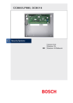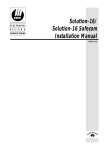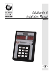
1
CC880/LP880, SC8016
Quick Reference Guide
EN
Solution-16,
Solution-16 Safecom
CC880/LP880, SC8016 | Quick Reference Guide | Notices
Copyright Notice
Notice of Liability
Unless otherwise indicated, this publication is the
copyright of Bosch Security Systems Pty Ltd
(“Bosch”). All rights are reserved.
This material is designed for use by tradespeople
with expertise in the installation of this product.
Persons without appropriate expertise should seek
assistance before attempting installation.
You may download a single copy of this publication.
By downloading the publication you agree that you
will: (i) only use the publication for your own
reference; (ii) not commercially exploit or charge any
person for the use of the publication; and (iii) not
modify the publication in any way without the prior
written permission of Bosch.
Except as specified above or where authorised by the
Copyright Act 1968 (Cth), no part of this publication
may be reproduced, transmitted, modified or stored,
in any form or by any means, without the prior
written permission of Bosch.
Bosch Security Systems | 6/04 | 4998152461B
EN | 2
While care has been taken in the preparation of this
material, Bosch Security Systems Pty Ltd and its
representatives will not be responsible to any person
or entity for any loss or damage directly or indirectly
caused by information in, or any omission from, this
material.
Bosch Security Systems Pty Ltd reserves the right to
make changes to features and specifications of its
products at any time without prior notification.
CC880/LP880, SC8016 | Quick Reference Guide | Table of Contents
Contents
1.
1.1
1.2
1.3
Overview ........................................................... 6
Introduction....................................................... 6
Programming..................................................... 6
Programming Using a Codepad ..................... 6
2.
Codepad Indicators .......................................... 7
3.
Programming Option Bits................................ 7
4.
4.1
4.1.1
4.1.2
4.1.3
4.1.4
4.3.8
4.3.9
4.3.10
4.3.11
4.3.12
4.3.13
4.3.14
4.3.15
4.3.16
4.3.17
4.3.18
4.3.19
4.3.20
4.3.21
4.3.22
4.3.23
4.3.24
Programming Commands ............................... 7
Arming the System (On).................................. 8
AWAY Mode.................................................... 8
STAY Mode 1................................................... 8
STAY Mode 2................................................... 8
Arm All Areas in AWAY Mode
(Partitioning)...................................................... 8
Disarming the System (Off) ............................. 8
AWAY Mode.................................................... 8
STAY Mode 1................................................... 8
STAY Mode 2................................................... 8
Disarm All Areas (Partitioning)....................... 8
Isolating Zones .................................................. 8
Standard Isolating............................................. 8
Code to Isolate.................................................. 8
Set First Test Report......................................... 8
Event Memory Recall ...................................... 8
Walk Test Mode ............................................... 8
Satellite Siren Service Mode ........................... 8
Telephone Monitor Mode (Toggle
On/Off) .............................................................. 8
Add a User Code.............................................. 9
Delete a User Code (V1.10) ............................ 9
Delete a User Code (V1.20+) ......................... 9
Change Domestic Telephone Numbers......... 9
Turn Outputs On/Off ...................................... 9
Set Date and Time............................................ 9
Day Alarm – Toggle On/Off (V1.10) ............ 9
Day Alarm – Toggle On/Off (V1.20+).......... 9
STAY Mode 2 Zones - Program ..................... 9
Fault Analysis .................................................... 9
Modem Call (Alarm Link)............................... 9
Latching Outputs (Reset) ................................. 9
Codepad ID/Buzzer Tone ............................. 10
Test Report...................................................... 10
Speaker Test .................................................... 10
Bell Test ........................................................... 10
Strobe Test (Toggle On/Off) ......................... 10
5.
5.1
5.1.1
Programming Parameters .............................. 10
Telephone Programming ............................... 10
Primary Telephone Number ......................... 10
4.2
4.2.1
4.2.2
4.2.3
4.2.4
4.3
4.3.1
4.3.2
4.3.3
4.3.4
4.3.5
4.3.6
4.3.7
Bosch Security Systems | 6/04 | 4998152461B
5.1.2
5.1.3
5.1.4
5.1.5
5.1.6
5.1.7
5.1.8
5.1.9
5.1.10
5.2
5.2.1
5.2.2
5.2.3
5.2.4
5.2.5
5.3
5.4
5.4.1
5.4.2
5.4.3
5.4.4
5.4.5
5.4.6
5.4.7
5.4.8
5.4.9
5.4.10
5.4.11
5.4.12
5.5
5.5.1
5.5.2
5.5.3
5.5.4
5.6
5.7
5.8
5.9
5.10
5.10.1
5.10.2
5.11
5.11.1
5.11.2
5.12
5.12.1
5.12.2
5.12.3
5.12.4
EN | 3
Secondary Telephone Number..................... 10
Call Back Telephone Number ...................... 10
Dialling Format............................................... 10
Handshake Tone ............................................ 10
Transmission Format...................................... 10
Transmission Speed ....................................... 10
Subscriber ID Number For Area 1 .............. 10
Installer Code.................................................. 10
Ring Count...................................................... 11
User Code Programming............................... 11
User Codes...................................................... 11
Authority Level Descriptions for
User Codes...................................................... 11
Auxiliary Codes.............................................. 11
Authority Level Descriptions for Auxiliary
Codes ............................................................... 12
User Code Retries .......................................... 12
EOL Resistor Value ....................................... 12
Zones Programming....................................... 12
Day Alarm Zones ........................................... 12
Zones................................................................ 12
Zone Types...................................................... 14
Zone Options .................................................. 14
Dialler Channel .............................................. 14
Zone Pulse Count ........................................... 14
Zone Pulse Count Time................................. 14
Event Code ..................................................... 14
Zone Bypass (Zone 1 to 8)............................. 14
Zone Bypass (Zone 9 to 16)........................... 14
Zone Trouble (Zone 1 to 8)........................... 14
Zone Trouble (Zone 9 to 16)......................... 14
Codepad Programming ................................. 15
Codepad Duress ............................................. 15
Codepad Panic................................................ 15
Access Denied (Code Retries)....................... 15
Codepad Lockout Time................................. 15
AC Fail ............................................................ 15
Low Battery..................................................... 15
Program Altered Code................................... 15
Sensor Watch (V1.10 to V1.31, V1.32) ....... 15
Reports Programming.................................... 15
Open/Close Reports for Area 1 ................... 15
Test Report Time (Automatic)...................... 15
PET Pager Programming............................... 16
PET Pager Network Password ...................... 16
PET Pager ID Number .................................. 16
Outputs Programming ................................... 16
Outputs ............................................................ 16
Output Event Types....................................... 17
Polarity (Modes) ............................................. 18
Time Base........................................................ 18
CC880/LP880, SC8016 | Quick Reference Guide | Table of Contents
5.12.5
5.12.6
5.12.7
5.13
5.13.1
5.13.2
5.13.3
5.13.4
5.13.5
5.13.6
5.13.7
5.13.8
5.14
5.15
5.16
5.16.1
5.16.2
5.16.3
5.16.4
5.17
5.17.1
5.17.2
5.17.3
5.18
5.18.1
5.18.2
5.19
5.19.1
5.19.2
5.19.3
5.19.4
5.19.5
5.19.6
5.19.7
5.20
5.20.1
5.20.2
5.20.3
5.20.4
5.21
5.22
5.22.1
5.22.2
5.22.3
5.23
5.23.1
5.23.2
Time Base Multiplier...................................... 18
One Shot Mode .............................................. 18
Pulsing Mode .................................................. 18
Entry and Exit Time Programming.............. 18
Entry Time 1 ................................................... 18
Entry Time 2 ................................................... 18
Entry Time 3 ................................................... 19
Entry Time 4 ................................................... 19
Exit Time for AWAY Mode ......................... 19
Entry Time for STAY Mode 1...................... 19
Entry Time for STAY Mode 2...................... 19
Entry Guard Time for STAY Modes
1 and 2 ............................................................. 19
Sensor Watch Time ........................................ 19
System Date (V1.10, V1.20+) ....................... 19
Auto Arming Time Programming ................ 19
Auto Arming Time ......................................... 19
Auto Arming Pre-Alert Time ........................ 19
Time Output Pre-Alert Time......................... 19
Auto Operation of the Timed Output.......... 19
Siren Programming ........................................ 20
Siren Run Time (V1.10 to V2.03,
V2.04+)............................................................ 20
Siren Sound Rate ............................................ 20
Swinger Shutdown Count for Siren and
Dialler (V1.10 to V1.37, V1.40).................... 20
Dialler Options Programming....................... 20
Dialler Options 1 ............................................ 20
Dialler Options 2 ............................................ 20
System Options Programming ...................... 20
System Options 1............................................ 20
System Options 2............................................ 20
System Options 3............................................ 20
System Options 4 (V1.10 only)..................... 20
System Options 4 (V1.20+) ........................... 20
System Options 5 (V1.37+) ........................... 20
System Options 6 (V1.33+) ........................... 20
Consumer Options Programming ................ 21
Consumer Options 1 (V1.10, V1.20+)......... 21
Consumer Options 2 ...................................... 21
DTMF Command Module Options ............. 21
Expansion Board Options (V1.10,
V1.20)............................................................... 21
Telephone Line Fail Options ........................ 21
Open/Close Reports Programming.............. 21
Open/Close Reports for Area 2.................... 21
Open/Close Reports for Area 3.................... 21
Open/Close Reports for Area 4.................... 21
Subscriber ID Programming ......................... 21
Subscriber ID Number for Area 2................ 21
Subscriber ID Number for Area 3................ 21
Bosch Security Systems | 6/04 | 4998152461B
EN | 4
5.23.3
5.24
5.24.1
5.24.2
5.24.3
5.24.4
5.25
5.26
5.27
5.28
5.28.1
5.28.2
5.28.3
5.28.4
5.28.5
5.28.6
5.28.7
5.29
5.30
5.31
5.32
Subscriber ID Number for Area 4................ 21
Zone Allocations Programming.................... 21
Zone Allocations for Area 1.......................... 21
Zone Allocations for Area 2.......................... 22
Zone Allocations for Area 3.......................... 22
Zone Allocations for Area 4.......................... 22
User Code Area Assignment......................... 22
Serial Printer Baud Rate ................................ 22
Dialler Lockout Count (V1.40+) .................. 22
Safecom Programming................................... 22
Safecom – RF Fail (V2.00+).......................... 22
Safecom – Telco Fail (V2.00+) ..................... 22
Safecom – RF Jamming (V2.00+) ................ 22
Safecom – RF Jamming Delay (V2.00+) ..... 22
Safecom RF Supervision Time (V2.02+)..... 22
Safecom Reporting Options (V2.00+) ......... 22
Safecom Interface Serial Number................. 22
Ring Burst Time (V2.04, V2.05+) ................ 23
Carrier Sync Options ..................................... 23
Default Options .............................................. 23
System Time ................................................... 23
6.
6.1
6.4
Connections .................................................... 24
Connection for Momentary or Latching
Keyswitch ........................................................ 24
Connections for Split EOL Resistors for 16
Zone Operation .............................................. 24
Connections for Split EOL Resistors for 16
Zone Operation Using N/O Contacts ......... 25
Codepad Connections (Partitioning)............ 25
7.
7.1
7.2
Wiring Diagrams ............................................ 27
Safecom Interface ........................................... 27
Component Overlays..................................... 28
6.2
6.3
Figures
Figure 1:
Figure 2:
Figure 3:
Figure 4:
Figure 5:
Figure 6:
Figure 7:
Figure 8:
Figure 9:
Connection for Momentary or Latching
Keyswitch ................................................. 24
Connections for Split EOL Resistors for
16 Zone Operation.................................. 24
Connections for Split EOL Resistors for
16 Zone Operation Using N/O
Contacts.................................................... 25
Code Connections (Partitioning) –
Master Plus Four Areas .......................... 25
Code Connections (Partitioning) – Four
Areas ......................................................... 26
Safecom Interface.................................... 27
Component Overlay 1............................ 28
Component Overlay 2............................ 29
Solution-16 Wiring Diagram.................. 30
CC880/LP880, SC8016 | Quick Reference Guide | Table of Contents
Tables
Table 1:
Table 2:
Table 3:
Table 4:
Table 5:
Table 6:
Table 7:
Quick Guide to Programming ................. 6
Codepad Indicators................................... 7
Programming Option Bits ........................ 7
Installer’s Programming Commands....... 7
Telephone Monitor Mode........................ 9
Fault Analysis............................................. 9
Codepad ID/Buzzer Tone...................... 10
Bosch Security Systems | 6/04 | 4998152461B
EN | 5
CC880/LP880, SC8016 | Quick Reference Guide | 1. Overview
1.
Overview
1.1
Introduction
Thank you for choosing the Solution Ultima 880
Model CC488 control panel for your installation.
You will find this system extremely flexible, reliable,
and easy to use. The quick reference guide supplied
with the system provides users with enough basic
information to wire, configure, and program the
system. Due to the systems many programmable
features and options, obtain the complete Installation
Manual that provides detailed information on system
options, functions, and programming methods.
1.2
Programming
The programming options of the system are stored in
a non-volatile EPROM. This memory holds all
information during a total power loss and can be
changed as many times as required.
The entire programming sequence consists of
entering a location number and changing the data as
required.
Use the following methods to program the system:
•
Codepad
•
Hand Held Programmer
•
Alarm Link Software
1.3
Programming Using a Codepad
The system must be disarmed (with no active alarm)
to program the system. If there is an active alarm or
the system is armed, enter the code for User 1
(Default = 2580) followed by the [#] key. User Code
1 is the Master Code factory default.
To enter installer’s programming mode, enter the
installer code (Default = 1234) followed by the [#]
key. Two beeps sound and both the STAY and
AWAY indicators flash simultaneously to indicate
that you entered programming mode. The codepad
indicators display the current data programmed in
LOCATION 000 (first location of the Primary
Telephone Number).
Bosch Security Systems | 6/04 | 4998152461B
EN | 6
To move to another programming location, enter the
location number followed by the [#] key. The data in
the new location is displayed using the codepad
indicators. (For example, if you entered [3 4 #], the
system jumps to LOCATION 034, the beginning of
the Subscriber ID Number for Receiver 1.)
To move to the next location, press the [#] key. This
steps you to the next location. The data in the next
location is displayed using the codepad indicators.
(For example, if you are currently positioned at
LOCATION 034, pressing the [#] key takes you to
LOCATION 035.)
To step back one location, press the [*] key. (For
example, if you are currently positioned at
LOCATION 35, pressing the [*] key takes you back
to LOCATION 34.)
To change data in the current location, enter the new
value (0 to 15) followed by the [*] key. This stores the
new data into the location. (For example, if you enter
the value [1 4 *], both the Zone 4 indicator and the
MAINS indicator display to represent the new data
value.)
To move to the next location, press the [#] key. The
data in the next location displays.
To exit Installer’s Programming Mode, enter
[9 6 0 #]. Two beeps sound and the STAY and
AWAY indicators no longer display. The system
returns to the disarmed state and is ready for use.
Table 1 displays a quick guide to programming:
Table 1:
Quick Guide to Programming
Task
Enter Installer’s
Programming Mode
Exit Installer’s Programming
Mode
Step to next location
Step back one location
Program new data into
location
Jump to another location
Keys to Press
[1 2 3 4 #]
[9 6 0 #]
[#]
[*]
[Data][*] (Data = 0 to 15)
[Location Number][#]
CC880/LP880, SC8016 | Quick Reference Guide | 2. Codepad Indicators
2.
Codepad Indicators
Table 2:
Data
Value
0
1
2
3
4
5
6
7
8
9
10
11
12
13
14
15
3.
Codepad Indicators
Zone 1
Indicator
Zone 2
Indicator
Zone 3
Indicator
Zone 4
Indicator
Zone 5
Indicator
Zone 6
Indicator
Zone 7
Indicator
Zone 8
Indicator
MAINS
Indicator
X
X
X
X
X
X
X
X
X
X
X
X
X
X
X
X
X
X
X
X
X
Programming Option Bits
Use option bits to program any combination of the
four different options in one location by adding the
options together. Programming a zero disables all
four options.
Example
Table 3:
4.
Programming Commands
Installer programming commands, displayed in Table
4, can only be used when you enter Installer’s
Programming Mode. Enter the command followed
by the [#] key.
Table 4:
If you only want options 1, 2, and 4, at LOCATION
177, add the numbers together. The total is the
number to program: 1 + 2 + 4 = 7.
Option
1
2
4
8
EN | 7
Command
958
Programming Option Bits
Description
Dialler reporting functions allowed.
Remote arming using telephone allowed.
Answering machine bypass only when armed.
Bell 103 used for FSK format
(Disabled = CCITT V21).
959
960
961
962
963
964
965
966
999
Bosch Security Systems | 6/04 | 4998152461B
Installer’s Programming Commands
Description
Enable/disable zone status (hand held
programmer required).
Test programming key.
Exit Installer’s Programming Mode.
Default system back to factory settings.
Copy panel memory to programming key.
Copy programming key to panel memory.
Erase programming key.
Default system for domestic dialling
format.
Enable/disable automatic stepping of
locations when programming.
Display software version (hand held
programmer required).
CC880/LP880, SC8016 | Quick Reference Guide | 4. Programming Commands
4.1
4.1.1
Arming the System (On)
AWAY Mode
Press and hold the [#] key until two beeps are heard.
Or
Enter your code followed by the [#] key (for
example, [2 5 8 0 #]).
4.1.2
STAY Mode 1
Press and hold the [*] key until two beeps are heard.
Or
Enter your code followed by the [*] key (for example,
[2 5 8 0 *]).
4.1.3
STAY Mode 2
Press and hold the [0] key until two beeps are heard.
4.1.4
Arm All Areas in AWAY Mode
(Partitioning)
Enter your code followed by [0] and then the [#] key
(for example, [2 5 8 0 *]).
Use this code to arm all areas that the code is
assigned simultaneously to in AWAY Mode without
arming each area individually.
4.2
4.2.1
Disarming the System (Off)
AWAY Mode
Enter your code followed by the [#] key (for
example, [2 5 8 0 #]).
4.2.2
STAY Mode 1
Press and hold the [*] key until two beeps are heard
(only if no alarm).
Or
Enter your code followed by the [#] key (for
example, [2 5 8 0 #]).
4.2.3
STAY Mode 2
Press the [0] key until two beeps are heard (only if no
alarm).
4.3
EN | 8
Isolating Zones
4.3.1
Standard Isolating
1. Press the [*] key twice.
2. Enter the zone number you want isolated
followed by the [*] key.
Repeat Step 2 if more than one zone must be
isolated.
3. Press the [#] key to exit when finished.
4.3.2
Code to Isolate
1. Press the [*] key once.
2. Enter your user code.
3. Enter the zone number you want isolated
followed by the [*] key.
Repeat Step 2 if more than one zone must be
isolated.
4. Press the [#] key to exit when finished.
4.3.3
Set First Test Report
1. Enter the four character Installer Code followed
by [2] and the [#] key (for example,
[1 2 3 4 2 #]).
2. Enter the number of days (0 to 99) to wait until
the first test report followed by the [#] key.
4.3.4
Event Memory Recall
Enter the four character Installer Code or Master
Code followed by [3] and the [#] key (for example,
[1 2 3 4 8 #]).
The last 40 events (non-partitioned) or last ten events
(partitioned) are displayed in reverse order (for
example, most recent to least recent).
4.3.5
Walk Test Mode
1. Enter the four character Installer Code or Master
Code followed by [4] and the [#] key (for
example, [1 2 3 4 4 #]).
2. Test each zone as required.
3. Press the [#] key to exit.
4.3.6
Satellite Siren Service Mode
Or
Enter the Installer Code followed by [5] and the [#]
key (for example, [1 2 3 4 5 #]).
Enter your code followed by the [#] key (for
example, [2 5 8 0 #]).
4.3.7
4.2.4
1.
Disarm All Areas (Partitioning)
Enter your code followed by [0] and then the [#] key
(for example, [2 5 8 0 *]).
Use this code to disarm all areas that the code is
assigned simultaneously without disarming each area
individually.
Bosch Security Systems | 6/04 | 4998152461B
2.
3.
Telephone Monitor Mode (Toggle
On/Off)
Enter the four character Installer Code followed
by [7] and the [#] key (for example,
[1 2 3 4 7 #]).
Press and hold the [9] key until two beeps sound
to send a Test Report.
When complete, repeat Step 1 to turn the
Telephone Monitor Mode off.
CC880/LP880, SC8016 | Quick Reference Guide | 4. Programming Commands
Table 5:
Zone LED
1
2
3
4
5
None
Telephone Monitor Mode
Dialling Event
Telephone line seized
Dialling telephone number
Handshake received
Data being sent
Kiss-off received
Released telephone line
4.3.8
Add a User Code
1. Enter the four character Master Code followed
by [1] and the [#] key (for example,
[2 5 8 0 1 #]).
2. Enter the user number you want to add/change
followed by the [#] key.
3. Enter the new code followed by the [#] key.
4.3.9
Delete a User Code (V1.10)
1. Enter the four character Master Code followed
by [1] and the [#] key (for example,
[2 5 8 0 1 #]).
2. Enter the user number you want to delete
followed by the [#] key.
3. Press the [#] key to delete the user code.
4.3.10
Delete a User Code (V1.20+)
1. Enter the four character Master Code followed
by [1] and the [#] key (for example,
[2 5 8 0 1 #]).
2. Enter the user number you want to delete
followed by the [#] key.
3. Press the [*] key to delete the user code.
4.3.11
Change Domestic Telephone Numbers
1. Enter the four character Master Code followed
by [2] and the [#] key (for example,
[2 5 8 0 2 #]).
2. Enter the digits for the telephone number.
3. If more than one telephone number, press the [*]
key and repeat Step 2, or press the [#] key to
exit.
4.3.12
Turn Outputs On/Off
1. Enter the four character Master Code followed
by [5] and the [#] key (for example,
[2 5 8 0 5 #]).
2. Enter the output number (1 to 5) that you want to
toggle on or off.
3. Press the [#] key to toggle on or the [*] key to
toggle off.
4. Press the [#] key to exit.
Bosch Security Systems | 6/04 | 4998152461B
EN | 9
4.3.13
Set Date and Time
1. Enter the four character Master Code followed
by [6] and the [#] key (for example,
[2 5 8 0 6 #]).
2. Enter the day (DD), month (MM), and year (YY)
followed by the hour (HH) and minute (MM).
3. Press the [#] key to exit.
4.3.14
Day Alarm – Toggle On/Off (V1.10)
Enter the four character Master Code followed by [7]
and the [#] key (for example, [2 5 8 0 7 #]).
4.3.15
Day Alarm – Toggle On/Off (V1.20+)
Press and hold the [4] key until two beeps are heard.
4.3.16
STAY Mode 2 Zones - Program
1. Enter the four character Master Code followed
by [8] and the [#] key (for example,
[2 5 8 0 8 #]).
2. Enter the zone number you want the system to
automatically isolate followed by the [*] key.
Repeat if more than one zone must be
automatically isolated when armed in STAY
Mode 2.
3. Press the [#] key to exit.
4.3.17
Fault Analysis
1. Press and hold the [5] key until two beeps are
heard.
2. Zone indicators display fault conditions (see
Table 6).
3. Press [#] key to exit.
Table 6:
Zone LED
1
2
3
4
5
6
7
8
4.3.18
Fault Analysis
FAULT Condition
Battery low
Date/time reset
Sensor watch fail
Horn speaker fail
Telephone line fail
EPROM fail
Fuse fail
Communication fail
Modem Call (Alarm Link)
Press and hold the [6] key until two beeps sound.
4.3.19
Latching Outputs (Reset)
Press and hold the [7] key until two beeps sound.
CC880/LP880, SC8016 | Quick Reference Guide | 5. Programming Parameters
4.3.20
Codepad ID/Buzzer Tone
1. Press and hold the [8] key until the desired
buzzer tone is reached.
If the system is partitioned, the codepad displays
a number to identify which area the codepad
belongs to (see Table 7).
2. Press the [#] key to exit.
Table 7:
Codepad ID/Buzzer Tone
5.1.4
4.3.21
Codepad Assignment
Area 1
Area 2
Area 3
Area 4
Master Partitioned Codepad
Test Report
Press and hold the [9] key until two beeps sound.
4.3.22
Speaker Test
Press and hold the [1] key until two beeps sound. The
speaker sounds for two seconds.
4.3.23
Bell Test
Press and hold the [2] key until two beeps sound. The
piezo sounds for 2 seconds.
4.3.24
Strobe Test (Toggle On/Off)
Press and hold the [3] key until three beeps sound to
turn the strobe on.
Or
Press and hold the [3] key until two beeps sound to
turn the strobe off.
5.
Programming Parameters
Shaded rows indicate default values.
5.1
5.1.1
Telephone Programming
Primary Telephone Number
000 to 015
Location
0
Default
0 = 10 and telephone termination = 0
Anywhere else 0 = 0
5.1.2
Secondary Telephone Number
Location 016 to 031
0
Default
0 = 10 and telephone termination = 0
Anywhere else 0 = 0
5.1.3
Call Back Telephone Number
Location 032 to 047
0
Default
0 = 10 and telephone termination = 0
Anywhere else 0 = 0
Bosch Security Systems | 6/04 | 4998152461B
Dialling Format
Location 048
1 Australian DTMF
2 Australian decadic
3 Alternate DTMF and decadic (Aust)
4 International DTMF
5 Reversed decadic
6 Alternate DTMF and reversed decadic
5.1.5
Zone LED
1
2
3
4
7
EN | 10
Handshake Tone
Location 049
1 HI-LO handshake (contact ID)
2 1400 Hz (Ademco TX @ 1900 Hz)
3 2300 Hz (Sescoa TX @ 1800 Hz)
4 No handshake
5 Pager
5.1.6
Transmission Format
Location 050
1
Contact ID
2
4 + 2 expressed
3
4 + 2 pulsed
4
4 + 2 pulsed + checksum
5
4 + 1 pulsed + universal
6
4 + 1 pulsed expanded
7
3 + 1 pulsed universal
8
3 + 1 pulsed expanded
9
Reserved
10 Reserved
11 Domestic
12 Basic pager
13 Reserved
14 PET alpha pager
15 Synthesised voice
5.1.7
Location
1
2
3
4
5
6
5.1.8
Location
Default
5.1.9
Location
Transmission Speed
051
1 pulse/second
10 pulses/second
15 pulses/second
20 pulses/second
20 pulses/second FDL
40 pulses/second
Subscriber ID Number For Area 1
052 to 055
0
Installer Code
056 to 062
Location
056
057
058
059
060
061
062
Default
1
2
3
4
15
15
15
CC880/LP880, SC8016 | Quick Reference Guide | 5. Programming Parameters
5.1.10
Ring Count
Location
Default
0
1 to 13
14
15
5.2
063
8
Panel will not answer
Number of rings until panel answers
Answering machine bypass 2 (V1.37+)
Answering machine bypass 1
User Code Programming
5.2.1
Location
User Codes
064 to 319
Location
Default
064
2
065
5
066
8
067
0
068 to 070
15
Authority Level* 071
8
072 to 078
15
User Code 2
Authority Level* 079
0
080 to 086
15
User Code 3
Authority Level* 087
0
088 to 094
15
User Code 4
Authority Level* 095
0
096 to 102
15
User Code 5
Authority Level* 103
0
104 to 110
15
User Code 6
Authority Level* 111
0
112 to 118
15
User Code 7
Authority Level* 119
0
120 to 126
15
User Code 8
Authority Level* 127
0
128 to 134
15
User Code 9
Authority Level* 135
0
136 to 142
15
User Code 10
Authority Level* 143
0
144 to 150
15
User Code 11
Authority Level* 151
0
152 to 158
15
User Code 12
Authority Level* 159
0
160 to 166
0
User Code 13
Authority Level* 167
0
168 to 174
15
User Code 14
Authority Level* 175
0
176 to 182
15
User Code 15
Authority Level* 183
0
184 to 190
15
User Code 16
Authority Level* 191
0
192 to 198
15
User Code 17
Authority Level* 199
0
200 to 206
15
User Code 18
Authority Level* 207
0
* See Section 5.2.2 Authority Level Descriptions for
User Codes for Authority Level descriptions.
User Code 1
Bosch Security Systems | 6/04 | 4998152461B
5.2.1
EN | 11
User Codes (continued)
Location
064 to 319
Location
Default
208 to 214
15
User Code 19
Authority Level* 215
0
216 to 222
15
User Code 20
Authority Level* 223
0
224 to 230
15
User Code 21
Authority Level* 231
0
232 to 238
15
User Code 22
Authority Level* 239
0
240 to 246
15
User Code 23
Authority Level* 247
0
248 to 254
15
User Code 24
Authority Level* 255
0
256 to 262
0
User Code 25
Authority Level* 263
0
264 to 270
15
User Code 26
Authority Level* 271
0
272 to 278
15
User Code 27
Authority Level* 279
0
280 to 286
15
User Code 28
Authority Level* 287
0
288 to 294
15
User Code 29
Authority Level* 295
0
296 to 302
15
User Code 30
Authority Level* 303
0
304 to 310
15
User Code 31
Authority Level* 311
0
312
0
User Code 32
313 to 318
15
Authority Level* 319
1
* See Section 5.2.2 Authority Level Descriptions for
User Codes for Authority Level descriptions.
5.2.2
Authority
Level
0
1
2
4
6
8
12
5.2.3
Location
Authority Level Descriptions for
User Codes
Description
Arm/disarm
Arm only
Patrolman code
Arm/disarm + Code required to isolate
Patrolman code + Code required to isolate
Master code + Arm/disarm
Master code + Arm/disarm + Code required
to isolate
Auxiliary Codes
320 to 335
Location
Default
320 to 326
15
Auxiliary Code 1
Authority Level* 327
2
328 to 334
15
Auxiliary Code 2
Authority Level* 335
2
* See Section 5.2.4 Authority Level Descriptions for
Auxiliary Codes for Authority Level descriptions.
CC880/LP880, SC8016 | Quick Reference Guide | 5. Programming Parameters
5.2.4
Authority Level Descriptions for
Auxiliary Codes
Authority
Level
1
2
3
4
5
6
7
5.2.5
Location
Operate when the system is armed
Operate when the system is disarmed
Operate when the system is armed or
disarmed
Operate always as long as no alarm
memories are present
Operate if armed and no alarm memories
are present
Operate if disarmed and no alarm memories
are present
Operate if armed or disarmed and no alarm
memories are present
338
6
Unlimited code retries
Number of incorrect code retries
EOL Resistor Value
Location 339
1
1K
2
1K5
3
2K2
4
3K3
5
3K9
6
4K7
7
5K6
8
6K8
9
10K
10 12K
11 22K
12 Reserved
13 Reserved
14 Reserved
15 Split EOL (3K3/6K8)
5.4
Zones Programming
5.4.1
Day Alarm Zones
Location
1
2
4
8
Zone 1
Zone 2
Zone 3
Zone 4
1
2
4
8
Zone 5
Zone 6
Zone 7
Zone 8
Zones
340 to 467
Description
User Code Retries
Location
Default
0
1 to 15
5.3
5.4.2
336 to 337
Location
336
Default
1
337
0
Bosch Security Systems | 6/04 | 4998152461B
EN | 12
Zone 1 (Default = Delay – 1)
Zone Type
Zone Options
Zone Pulse Count
Zone Pulse Count Time
Event Code Hundreds Digit
Event Code Tens Digit
Event Code Units Digit
Dialler Channel
Zone 2 (Default = Handover)
Zone Type
Zone Options
Zone Pulse Count
Zone Pulse Count Time
Event Code Hundreds Digit
Event Code Tens Digit
Event Code Units Digit
Dialler Channel
Zone 3 (Default = Handover)
Zone Type
Zone Options
Zone Pulse Count
Zone Pulse Count Time
Event Code Hundreds Digit
Event Code Tens Digit
Event Code Units Digit
Dialler Channel
Zone 4 (Default = Handover)
Zone Type
Zone Options
Zone Pulse Count
Zone Pulse Count Time
Event Code Hundreds Digit
Event Code Tens Digit
Event Code Units Digit
Dialler Channel
Zone 5 (Default = Handover)
Zone Type
Zone Options
Zone Pulse Count
Zone Pulse Count Time
Event Code Hundreds Digit
Event Code Tens Digit
Event Code Units Digit
Dialler Channel
Location
Default
340
341
342
343
344
345
346
347
2
0
0
0
1
3
0
1
348
349
350
351
352
353
354
355
1
0
0
0
1
3
0
1
356
357
358
359
360
361
362
363
1
0
0
0
1
3
0
1
364
365
366
367
368
369
370
371
1
0
0
0
1
3
0
1
372
373
374
375
376
377
378
379
1
0
0
0
1
3
0
1
CC880/LP880, SC8016 | Quick Reference Guide | 5. Programming Parameters
5.4.2
5.4.2
Zones (continued)
Location
340 to 467
Zones (continued)
Location
Location
Zone 6 (Default = Instant)
Zone Type 380
Zone Options 381
Zone Pulse Count 382
Zone Pulse Count Time 383
Event Code Hundreds Digit 384
Event Code Tens Digit 385
Event Code Units Digit 386
Dialler Channel 387
Zone 7 (Default = Instant)
Zone Type 388
Zone Options 389
Zone Pulse Count 390
Zone Pulse Count Time 391
Event Code Hundreds Digit 392
Event Code Tens Digit 393
Event Code Units Digit 394
Dialler Channel 395
Zone 8 (Default = 24 hr. Burglary)
Zone Type 396
Zone Options 397
Zone Pulse Count 398
Zone Pulse Count Time 399
Event Code Hundreds Digit 400
Event Code Tens Digit 401
Event Code Units Digit 402
Dialler Channel 403
Zone 9 (Default = Instant)
Zone Type 404
Zone Options 405
Zone Pulse Count 406
Zone Pulse Count Time 407
Event Code Hundreds Digit 408
Event Code Tens Digit 409
Event Code Units Digit 410
Dialler Channel 411
Zone 10 (Default = Instant)
Zone Type 412
Zone Options 413
Zone Pulse Count 414
Zone Pulse Count Time 415
Event Code Hundreds Digit 416
Event Code Tens Digit 417
Event Code Units Digit 418
Dialler Channel 419
Bosch Security Systems | 6/04 | 4998152461B
340 to 467
Default
0
0
0
0
1
3
0
1
0
0
0
0
1
3
0
1
12
0
0
0
1
3
3
1
0
0
0
0
1
3
0
1
0
0
0
0
1
3
0
1
EN | 13
Zone 11 (Default = Instant)
Zone Type
Zone Options
Zone Pulse Count
Zone Pulse Count Time
Event Code Hundreds Digit
Event Code Tens Digit
Event Code Units Digit
Dialler Channel
Zone 12 (Default = Instant)
Zone Type
Zone Options
Zone Pulse Count
Zone Pulse Count Time
Event Code Hundreds Digit
Event Code Tens Digit
Event Code Units Digit
Dialler Channel
Zone 13 (Default = Instant)
Zone Type
Zone Options
Zone Pulse Count
Zone Pulse Count Time
Event Code Hundreds Digit
Event Code Tens Digit
Event Code Units Digit
Dialler Channel
Zone 14 (Default = Instant)
Zone Type
Zone Options
Zone Pulse Count
Zone Pulse Count Time
Event Code Hundreds Digit
Event Code Tens Digit
Event Code Units Digit
Dialler Channel
Zone 15 (Default = Instant)
Zone Type
Zone Options
Zone Pulse Count
Zone Pulse Count Time
Event Code Hundreds Digit
Event Code Tens Digit
Event Code Units Digit
Dialler Channel
Location
Default
420
421
422
423
424
425
426
427
0
0
0
0
1
3
0
1
428
429
430
431
432
433
434
435
0
0
0
0
1
3
0
1
436
437
438
439
440
441
442
443
0
0
0
0
1
3
0
1
444
445
446
447
448
449
450
451
0
0
0
0
1
3
0
1
452
453
454
455
456
457
458
459
0
0
0
0
1
3
0
1
CC880/LP880, SC8016 | Quick Reference Guide | 5. Programming Parameters
5.4.2
Location
5.4.3
Zone Type
0
1
2
3
4
5
6
7
8
9
10
11
12
13
14
15
Option
1
2
4
8
5.4.5
Option
1
2
3
4
5.4.6
Option
Location
Default
460
461
462
463
464
465
466
467
0
0
0
0
1
3
0
1
Zone Types
Description
Instant
Handover
Delay-1
Delay-2
Delay-3
Delay-4
Instant (auto isolated in STAY Mode 1)
Handover (auto isolated in STAY Mode 1)
Delay-1 (auto isolated in STAY Mode 1)
Delay-2 (auto isolated in STAY Mode 1)
Delay-3 (auto isolated in STAY Mode 1)
Delay-4 (auto isolated in STAY Mode 1)
24-hour burglary
24-hour fire
Chime
Not used
Zone Options
Description
Lockout siren
Lockout dialler
Silent alarm
Sensor watch
Dialler Channel
Description
Group 1 (Area 1)
Group 2 (Area 2)
Group 3 (Area 3)
Group 4 (Area 4)
Zone Pulse Count Time
0
1
2
3
4
5
6
7
20 ms Loop
Response Time
(seconds)
0.5
1
2
3
4
5
10
15
5.4.8
Event Code
340 to 467
Zone 16 (Default = Instant)
Zone Type
Zone Options
Zone Pulse Count
Zone Pulse Count Time
Event Code Hundreds Digit
Event Code Tens Digit
Event Code Units Digit
Dialler Channel
5.4.4
5.4.7
Zones (continued)
Bosch Security Systems | 6/04 | 4998152461B
Option
8
9
10
11
12
13
14
15
150 ms Loop
Response Time
(seconds)
20
30
40
50
60
90
120
200
The three-digit event code describes the zone
function when reporting in Contact ID format (for
example, entry/exit, tamper, perimeter, and so on).
Refer to the Installation Manual for a full list of
available Contact ID codes. When the system reports
in a format other than Contact ID, the event code is
programmed as follows:
•
Hundreds Digit = Alarm Restore Report (0 =
Alarm Restore Disabled)
•
Tens Digit = Alarm Report
•
Units Digit = Channel Code (0 = Disabled)
5.4.9
Location
Zone Bypass (Zone 1 to 8)
468 to 469
Bypass Report
Bypass Restore Report
5.4.10
Location
Location
Location
Location
470
471
Default
9
9
Zone Trouble (Zone 1 to 8)
472 to 473
Trouble Report
Trouble Restore Report
5.4.12
Default
9
9
470 to 471
Bypass Report
Bypass Restore Report
5.4.11
Location
468
469
Zone Bypass (Zone 9 to 16)
Location
472
473
Default
9
9
Zone Trouble (Zone 9 to 16)
474 to 475
Zone Pulse Count
Use to program the number of pulses (0 to 15)
needed to register within the pulse count time to
activate an alarm.
EN | 14
Trouble Report
Trouble Restore Report
Location
474
475
Default
9
9
CC880/LP880, SC8016 | Quick Reference Guide | 5. Programming Parameters
5.5
5.5.1
Contact ID Event Code
Hundreds
Tens
Units
Dialler Channel
476
477
478
479
1
2
1
1
Location
Default
480 to 483
Contact ID Event Code
Hundreds
Tens
Units
Dialler Channel
5.5.3
480
481
482
483
1
2
0
1
Access Denied (Code Retries)
Location
Contact ID Event Code
Hundreds
Tens
Units
Dialler Channel
5.9
5.5.4
Location
Default
484
485
486
487
4
2
1
1
Codepad Lockout Time
Location
Location
640
Default
0
641
0
Location
Default
488
489
490
491
3
0
1
1
Location
Default
492
493
494
495
3
0
9
1
Low Battery
Location
492 to 495
Contact ID Event Code
Hundreds
Tens
Units
Dialler Channel
Bosch Security Systems | 6/04 | 4998152461B
496
497
498
499
3
0
6
0
Location
Default
500
501
502
503
3
8
3
1
Location
Default
500
501
502
503
3
0
7
1
Reports Programming
Location
Open/Close Reports for Area 1
504 to 505
Open Report
Close Report
Location
488 to 491
Contact ID Event Code
Hundreds
Tens
Units
Dialler Channel
Contact ID Event Code
Hundreds
Tens
Units
Dialler Channel
5.10.2
AC Fail
Default
500 to 503 (V1.10 to V1.31)
Contact ID Event Code
Hundreds
Tens
Units
Dialler Channel
500 to 503 (V1.32)
Location
5.10.1
640 to 641
Increments of 1 seconds
(0 seconds to 15 seconds)
Increments of 16 seconds
(0 seconds to 240 seconds)
Location
Location
5.10
Location
Sensor Watch (V1.10 to V1.31,
V1.32)
484 to 487
Contact ID Event Code
Hundreds
Tens
Units
Dialler Channel
5.7
Default
Codepad Panic
Location
496 to 499
476 to 479
Location
5.5.2
Program Altered Code
Location
Codepad Duress
Location
5.6
5.8
Codepad Programming
EN | 15
Location
504
505
Default
8
9
Test Report Time (Automatic)
506 to 513
Location
Hour of day (tens digit)
506
Hour of day (units digit)
507
Minute of day (tens digit)
508
Minute of day (units digit)
509
Repeat interval (tens digit)
510
Repeat interval (units digit)
511
Expansion code
512
Test Report options
513
1 Test Reports Only When Armed
2 Test Reports On All Areas
Default
0
0
0
0
0
0
9
0
CC880/LP880, SC8016 | Quick Reference Guide | 5. Programming Parameters
5.11
PET Pager Programming
5.11.1
5.12.1 Outputs (continued)
Location
PET Pager Network Password
Location
514 to 529
Location
Default
514
7
515
0
516
6
517
1
518
7
519
3
520
7
521
3
522
7
523
7
524
6
525
4
526 to 529
0
Telecom expects to see the password “passwd” sent
before the message is transmitted. The password is
programmed using ASCII text.
5.11.2
PET Pager ID Number
The Pager ID Number locations store the unique
number that allows the network to identify individual
pagers. When programming the system to report
using SMS messaging to a mobile phone, enter the
mobile phone number as the PET pager ID number.
To program the Pager ID Number, enter the decimal
characters that represent the Pager ID Number.
Remember to substitute a ten for a zero and to
terminate the number with a zero as you would if
you were programming the telephone numbers.
Location
Default
5.12
530 to 539
0
Outputs Programming
5.12.1
Location
Outputs
540 to 623
Output 1 (Default = EDMSAT)
Event Code
Event Code
Polarity
Time Base
Time Base Multiplier
Time Base Multiplier
Output 2 (Default = EDMSAT)
Event Code
Event Code
Polarity
Time Base
Time Base Multiplier
Time Base Multiplier
Location
Default
540
541
542
543
544
545
0
0
0
0
0
0
546
547
548
549
550
551
0
0
0
0
0
0
Bosch Security Systems | 6/04 | 4998152461B
EN | 16
540 to 623
Location
Default
Strobe Output (Default = Smoke Detector Reset)
Event Code 552
0
Event Code 553
1
Polarity 554
10
Time Base 555
2
Time Base Multiplier 556
0
Time Base Multiplier 557
3
Output 4 (Default = Strobe)
Event Code 558
2
Event Code 559
0
Polarity 560
1
Time Base 561
0
Time Base Multiplier 562
0
Time Base Multiplier 563
0
Output 5 (Default = Sirens Running)
Event Code 564
1
Event Code 565
15
Polarity 566
1
Time Base 567
0
Time Base Multiplier 568
0
Time Base Multiplier 569
0
Output 6 (Default = Codepad – Entry/Exit + D Alarm)
Event Code 570
0
Event Code 571
12
Polarity 572
2
Time Base 573
1
Time Base Multiplier 574
0
Time Base Multiplier 575
1
Output 7 (Default = Area 1 in Alarm – Siren)
Event Code 576
5
Event Code 577
2
Polarity 578
6
Time Base 579
3
Time Base Multiplier 580
1
Time Base Multiplier 581
0
Output 8 (Default = Area 1 in Alarm – Strobe)
Event Code 582
5
Event Code 583
2
Polarity 584
6
Time Base 585
3
Time Base Multiplier 586
6
Time Base Multiplier 587
0
Output 9 (Default = Area 2 in Alarm – Siren)
Event Code 588
5
Event Code 589
3
Polarity 590
6
Time Base 591
3
Time Base Multiplier 592
1
Time Base Multiplier 593
0
CC880/LP880, SC8016 | Quick Reference Guide | 5. Programming Parameters
5.12.1 Outputs (continued)
Location
540 to 623
Location
Default
Output 10 (Default = Area 2 in Alarm – Strobe)
Event Code 594
5
Event Code 595
3
Polarity 596
6
Time Base 597
3
Time Base Multiplier 598
6
Time Base Multiplier 599
0
Output 11 (Default = Area 3 in Alarm – Siren)
Event Code 600
5
Event Code 601
4
Polarity 602
6
Time Base 603
3
Time Base Multiplier 604
1
Time Base Multiplier 605
0
Output 12 (Default = Area 3 in Alarm – Strobe)
Event Code 606
5
Event Code 607
4
Polarity 608
6
Time Base 609
3
Time Base Multiplier 610
6
Time Base Multiplier 611
0
Output 13 (Default = Area 4 in Alarm – Siren)
Event Code 612
5
Event Code 613
5
Polarity 614
6
Time Base 615
3
Time Base Multiplier 616
1
Time Base Multiplier 617
0
Output 14 (Default = Area 4 in Alarm – Strobe)
Event Code 618
5
Event Code 619
5
Polarity 620
6
Time Base 621
3
Time Base Multiplier 622
6
Time Base Multiplier 623
0
5.12.2
Event
Code
0 0
0 0
0 0
0 1
0 2
0 3
0 4
0 4
0 5
0 6
0
0
0
7
8
9
Output Event Types
Description
EDMSAT – Satellite siren (output 1 only)
EDMSTU – Secuitel (output 2 only)
Serial printer (output 3 only)
System armed
System disarmed
Armed in STAY Mode
Pre-arming alert (V1.10)
Armed in AWAY (V1.20+)
Pre-arming alert (V1.20+)
Exit warning (all zones sealed) and entry
warning
Exit warning
Exit warning finished
Kiss-off after end of exit time
Bosch Security Systems | 6/04 | 4998152461B
5.12.2 Output Event Types (continued)
Event
Code
0 10
0 11
0 12
0 13
0 14
0 15
1 0
1 1
1 2
1 3
1 4
1 5
1 6
1 7
1 8
1 9
1 10
1 11
1 12
1 13
1 14
1 15
2 0
2 1
2 2
2 3
2 4
2 5
2 6
2 7
2 8
2 9
2 10
2 11
2 12
2 13
2 14
2 15
3 0
3 1
3 2
3 3
3 4
3 5
3 6
3 7
3 8
3 9
3 10
3 11
3 12
3 13
Description
Reserved
Entry warning
Entry warning and day alarm resetting
Reserved
Day alarm (resetting)
Day alarm (latching)
Day alarm enabled (V1.20+)
Timed output
Pre-alert warning for timed output
Reserved
AC fail
Low battery
Horn speaker fail
Sensor watch alarm
Codepad medical alarm (V1.37+)
Codepad fire alarm (V1.37+)
Codepad panic alarm
Codepad duress alarm
Access denied (code retries)
Speaker beeps (V1.37+)
Reserved
Sirens running
Strobe
Silent alarm
Alarm in STAY Mode
Alarm in AWAY Mode
Reserved
Fire alarm (resetting)
Fire alarm (latching)
Fire alarm (verification)
Remote control 1
Remote control 2
Remote control 3
Remote control 4
Auxiliary code 1
Auxiliary code 2
Telephone line fail
Communications fail after three attempts
Communications fail
Dialler disabled
Dialler active (on-line)
Ring detect (V1.37+)
Reserved
Mimic zone 1
Mimic zone 2
Mimic zone 3
Mimic zone 4
Mimic zone 5
Mimic zone 6
Mimic zone 7
Mimic zone 8
Mimic zone 9
EN | 17
CC880/LP880, SC8016 | Quick Reference Guide | 5. Programming Parameters
5.12.2 Output Event Types (continued)
Event
Code
3 14
3 15
4 0
4 1
4 2
4 3
4 4
4 5
4 6
4 7
4 8
4 9
4 10
4 11
4 12
4 13
4 14
4 15
5 0
5 1
5 2
5 3
5 4
5 5
5 6
5 7
5 8
5 9
5 10
5 11
5 12
5 13
5 14
5 15
6 0
6 1
6 2
6 3
Description
Mimic zone 10
Mimic zone 11
Mimic zone 12
Mimic zone 13
Mimic zone 14
Mimic zone 15
Mimic zone 16
Chime
Zone not sealed
Reserved
Reserved
Reserved
Area 1 – zone unsealed
Area 2 – zone unsealed
Area 3 – zone unsealed
Area 4 – zone unsealed
Reserved
Reserved
Reserved
AC main 50 Hz/60 Hz
Area 1 in alarm
Area 2 in alarm
Area 3 in alarm
Area 4 in alarm
Area 1 armed
Area 2 armed
Area 3 armed
Area 4 armed
Area 1 disarmed
Area 2 disarmed
Area 3 disarmed
Area 4 disarmed
Any areas armed
Any areas disarmed
Area 1 codepad data terminal
Area 2 codepad data terminal
Area 3 codepad data terminal
Area 4 codepad data terminal
5.12.3
Polarity (Modes)
Option
0
1
2
3
4
5
6
7
8
9
10
11
12
13
Description
Disabled
Normally open, going low
Normally open, pulsing low
Normally open, one shot low
Normally open, one shot low (reset)
Normally open, one shot low (re-trigger)
Normally open, latching low
Reserved
Normally low, going open
Normally low, pulsing open
Normally low, one shot open
Normally low, one shot open (reset)
Normally low, one shot open (re-trigger)
Normally low, latching open
5.12.4
Time Base
Option
1
2
3
4
Description
200 ms
1 second
1 minute
1 hour
5.12.5
Time Base Multiplier
Enter a value between 01 and 99.
5.12.6
One Shot Mode
When you program the output polarity as one shot,
the time base is multiplied by the time base
multiplier. For example, if the time base = 2 and the
multiplier = 05, the output operates for 10 seconds.
5.12.7
Pulsing Mode
When you program the output polarity as pulsing,
the time base becomes the ON time and the
multiplier becomes the OFF time. The OFF time is
the time base x the multiplier. For example, if you
want the output to pulse 1 second ON and 5 seconds
OFF, you would program the time base as one and
the multiplier as five.
5.13
Entry and Exit Time Programming
5.13.1
Location
Entry Time 1
624 to 625
Increments of 1 second
(0 seconds to 15 seconds)
Increments of 16 seconds
(0 seconds to 240 seconds)
5.13.2
Location
Location
624
Default
10
625
0
Location
626
Default
4
627
1
Entry Time 2
626 to 627
Increments of 1 seconds
(0 seconds to 15 seconds)
Increments of 16 seconds
(0 seconds to 240 seconds)
Bosch Security Systems | 6/04 | 4998152461B
EN | 18
CC880/LP880, SC8016 | Quick Reference Guide | 5. Programming Parameters
5.13.3
Entry Time 3
Location
628 to 629
Increments of 1 seconds
(0 seconds to 15 seconds)
Increments of 16 seconds
(0 seconds to 240 seconds)
5.13.4
Default
14
629
1
630 to 631
Increments of 1 seconds
(0 seconds to 15 seconds)
Increments of 16 seconds
(0 seconds to 240 seconds)
5.13.5
Location
630
Default
8
631
2
Exit Time for AWAY Mode
Location
632 to 633
Increments of 1 seconds
(0 seconds to 15 seconds)
Increments of 16 seconds
(0 seconds to 240 seconds)
5.13.6
Location
632
Default
12
633
3
Increments of 1 seconds
(0 seconds to 15 seconds)
Increments of 16 seconds
(0 seconds to 240 seconds)
5.13.7
Location
634
Default
12
635
3
636 to 637
Increments of 1 seconds
(0 seconds to 15 seconds)
Increments of 16 seconds
(0 seconds to 240 seconds)
5.13.8
Location
636
Default
12
637
3
Entry Guard Time for STAY Modes 1
and 2
Location
638 to 639
Increments of 1 seconds
(0 seconds to 15 seconds)
Increments of 16 seconds
(0 seconds to 240 seconds)
Location
638
Default
12
639
3
Sensor Watch Time
Location
642 to 643
Increments of 1 seconds
(0 seconds to 15 seconds)
Increments of 16 seconds
(0 seconds to 240 seconds)
5.16
Location
642
Default
0
643
0
Bosch Security Systems | 6/04 | 4998152461B
Location
644
Default
1
645
1
646
647
648
649
0
1
9
5
Location
644
645
646
647
648
649
Default
0
1
0
1
9
5
Auto Arming Time Programming
Auto Arming Time
650 to 653
Hour of the day (tens digit)
Hour of the day (units digit)
Minute of the day (tens digit)
Minute of the day (units digit)
5.16.2
Entry Time for STAY Mode 2
Location
Day of the month (tens digit)
Day of the month (units digit)
Month of the year (tens digit)
Month of the year (units digit)
Current year (tens digit)
Current year (units digit)
Location
634 to 635
644 to 649 (V1.10)
Day of the week
(Sun = 1, Sat = 2)
Month of the year
(Jan = 1, Dec = 12)
Day of the month (tens digit)
Day of the month (units digit)
Current year (tens digit)
Current year (units digit)
644 to 649 (V1.20+)
Location
5.16.1
Entry Time for STAY Mode 1
Location
System Date (V1.10, V1.20+)
Location
Location
628
Entry Time 4
Location
5.14
5.15
EN | 19
Location
Default
0
1 to 15
5.16.3
Location
Default
0
1 to 15
5.16.4
Location
Location
650
651
652
653
Default
0
0
0
0
Auto Arming Pre-Alert Time
654
5
No pre-alert time
Pre-alert time in minutes
Time Output Pre-Alert Time
655
5
No pre-alert time
Pre-alert time in minutes
Auto Operation of the Timed Output
656 to 659
Hour of the day (tens digit)
Hour of the day (units digit)
Minute of the day (tens digit)
Minute of the day (units digit)
Location
656
657
658
659
Default
0
0
0
0
CC880/LP880, SC8016 | Quick Reference Guide | 5. Programming Parameters
5.17
Siren Programming
5.17.1
Siren Run Time (V1.10 to V2.03, V2.04+)
Location
Default
0
1 to 15
Location
Default
0
1 to 15
5.17.2
Siren Sound Rate
Location
Default
0
15
5.17.3
Location
Default
0
1 to 15
5.18.1
661
7
Slowest frequency
Fastest frequency
Swinger Shutdown Count for Siren and
Dialler (V1.10 to V1.37, V1.40)
Location
Default
0
1 to 15
5.18
660 (V1.10 to V2.03)
10
No siren time
Siren time in minutes
660 (V2.04+)
5
No siren time
Siren time in minutes
662 (V1.10 to V1.37)
0
No lockout
Number of times siren/dialler operate until
lockout
662 (V1.40)
0
No lockout
Number of times siren operate until lockout
Dialler Options Programming
Dialler Options 1
663
Location
1 Dialler reporting functions allowed (disabled in
V2.00, also disable Safecom)
2 Remote arming via telephone allowed
4 Upload/download via alarm link allowed
8 Terminate alarm link session on alarm
5.18.2
Dialler Options 2
664
Location
0
Default
1 Open/close reports only after alarm
2 First to open/last to close reporting (partitioned
systems only)
4 Open/Close Reports in STAY Mode allowed
8 Answering machine bypass only when armed
(V1.31+)
5.19
5.19.1
System Options Programming
System Options 1
665
Location
1 Forced arming allowed
2 Smart lockout allowed
4 Horn speaker monitor
8 Horn speaker beeps allowed
Bosch Security Systems | 6/04 | 4998152461B
5.19.2
EN | 20
System Options 2
666
Location
1 Keyswitch interface, night arm station, or RE005
installed
2 Handover delay to be sequential
4 Codepad panic to be silent
8 Access denied (code retries/codepad tamper) to be
silent
5.19.3
System Options 3
667
Location
0
Default
1 Area 1 codepad connected to main data terminal
2 Modem module required for alarm link operation
4 AC fail after 1 hour (Disabled = after 2 minutes)
8 Pulse count handover allowed
5.19.4
System Options 4 (V1.10 only)
668
Location
0
Default
1 Delay audible alarm until communication complete
2 Reset alarm outputs from any area (partitioned
systems only)
4 Auto arm in AWAY mode
8 Auto arm in STAY mode 1
5.19.5
System Options 4 (V1.20+)
668
Location
0
Default
1 Delay audible alarm until communication complete
2 Reset alarm outputs from any area (partitioned
systems only)
4 Ignore AC mains fail (V1.30+)
8 Auto arm in STAY Mode 1
5.19.6
Location
System Options 5 (V1.37+)
897
0
Default
1
Send Test Report at end of siren time
2
Power up in disarmed state (re-boot)
4
Internal crystal to keep time (V1.40+)
8
Reserved
5.19.7
System Options 6 (V1.33+)
898
Location
1
Busy tone detection for domestic dialling allowed
2
Kiss-off detection for domestic dialling allowed
4
Extend acknowledge time from 30 seconds to
60 seconds
8
If battery failed, restrict battery test only on arming
(V1.35+)
CC880/LP880, SC8016 | Quick Reference Guide | 5. Programming Parameters
5.20
5.20.1
Consumer Options Programming
Consumer Options 1 (V1.10, V1.20+)
669 (V1.10 only)
Location
1 Entry guard time in STAY Mode
2 Audible alarm in STAY Mode allowed
4 User code required to isolate zones
8 Codepad Extinguish Mode allowed
669 (V1.20+)
Location
1 STAY LED to display day alarm on/off status
2 Audible alarm in STAY Mode allowed
4 AUX LED to display dialler on-line (partitioned
codepad only)
8 Codepad Extinguish Mode allowed
5.20.2
DTMF Command Module Options
671
Location
0
Default
1 Access to installer’s programming mode allowed
2 Installer code functions allowed
4 Disarming and auxiliary code functions allowed
8 Master code functions allowed
5.20.4
Telephone Line Fail Options
673
Location
0
Default
1
Display FAULT indicator if telephone line fails
2* Sound alarm when system is armed if telephone
line fails
4* Sound alarm when system is disarmed if telephone
line fails
*
Options 2 and 4 must be used in conjunction with Option
1 (for example, program a 1, 3, 5, or 7).
5.22
Open/Close Reports Programming
5.22.1
Open/Close Reports for Area 2
Location
674 to 675
Consumer Options 2
670
Location
1 User Code + 0 + AWAY function to arm/disarm all
areas allowed
2 Single button arming allowed (AWAY/STAY Modes
1 and 2)
4 Single button disarming allowed (STAY Modes 1
and 2)
8 Alarm reset memory on disarm
5.20.3
5.21
Expansion Board Options (V1.10, V1.20)
672 (V1.10)
Location
0
Default
1
Zone expansion board installed
2
Output expansion board installed
4
Momentary keyswitch input
8
Latching keyswitch input
672 (V1.20)
Location
0
Default
1
Zone expansion board installed
2
Output expansion board installed
3
Momentary keyswitch input
4
Latching keyswitch input
5
Momentary arm in AWAY Mode
6
Momentary arm in STAY Mode 1
7
Momentary arm in STAY Mode 2
8
Momentary disarm
9
Momentary arm area 4
10 Momentary disarm area 4
11 Momentary arm/disarm area 4
12 Latching arm/disarm area 4
Bosch Security Systems | 6/04 | 4998152461B
EN | 21
Open Report
Close Report
5.22.2
676 to 677
Open Report
Close Report
5.22.3
Location
676
677
Default
0
0
Open/Close Reports for Area 4
Location
678 to 679
Open Report
Close Report
Location
678
679
Default
0
0
Subscriber ID Programming
5.23.1
Subscriber ID Number for Area 2
Location
Default
5.23.2
680 to 683
0
Subscriber ID Number for Area 3
Location
Default
5.23.3
684 to 687
0
Subscriber ID Number for Area 4
Location
Default
5.24
Default
0
0
Open/Close Reports for Area 3
Location
5.23
Location
674
675
688 to 691
0
Zone Allocations Programming
5.24.1
Location
Zone Allocations for Area 1
692 to 699
Zone 1 LED – Area 1 Codepad
Zone 2 LED – Area 1 Codepad
Zone 3 LED – Area 1 Codepad
Zone 4 LED – Area 1 Codepad
Zone 5 LED – Area 1 Codepad
Zone 6 LED – Area 1 Codepad
Zone 7 LED – Area 1 Codepad
Zone 8 LED – Area 1 Codepad
Location
692
693
694
695
696
697
698
699
Default
0
0
0
0
0
0
0
0
CC880/LP880, SC8016 | Quick Reference Guide | 5. Programming Parameters
5.24.2
700 to 707
Zone 1 LED – Area 2 Codepad
Zone 2 LED – Area 2 Codepad
Zone 3 LED – Area 2 Codepad
Zone 4 LED – Area 2 Codepad
Zone 5 LED – Area 2 Codepad
Zone 6 LED – Area 2 Codepad
Zone 7 LED – Area 2 Codepad
Zone 8 LED – Area 2 Codepad
5.24.3
Default
0
0
0
0
0
0
0
0
Location
708
709
710
711
712
713
714
715
Default
0
0
0
0
0
0
0
0
716 to 723
Zone 1 LED – Area 4 Codepad
Zone 2 LED – Area 4 Codepad
Zone 3 LED – Area 4 Codepad
Zone 4 LED – Area 4 Codepad
Zone 5 LED – Area 4 Codepad
Zone 6 LED – Area 4 Codepad
Zone 7 LED – Area 4 Codepad
Zone 8 LED – Area 4 Codepad
Location
716
717
718
719
720
721
722
723
Default
0
0
0
0
0
0
0
0
User Code Area Assignment
724 to 755
Location
User Code 1 to 32
0 User code not assigned
1 User code assigned to Area 1
2 User code assigned to Area 2
4 User code assigned to Area 3
8 User code assigned to Area 4
5.26
Serial Printer Baud Rate
756
Location
1
300 baud
2
600 baud
3
1200 baud
4
2400 baud
5.27
Dialler Lockout Count (V1.40+)
Location
Default
0
1 to 15
760 to 763
Contact ID Event Code
Hundreds
Tens
Units
Dialler Channel (Point ID = 30
Hexadecimal/48 decimal)
5.28.2
Location
Zone Allocations for Area 4
Location
Location
Safecom – RF Fail (V2.00+)
757
0
No lockout
Number of times dialler operates until
lockout
Bosch Security Systems | 6/04 | 4998152461B
Location
Location
Default
0
1 to 15
5.28.5
Location
Default
0
1 to 15
5.28.6
760
761
762
763
3
5
3
1
Location
Default
764
765
766
767
3
5
1
1
Safecom – RF Jamming (V2.00+)
768 to 771
Contact ID Event Code
Hundreds
Tens
Units
Dailler Channel (Point ID = 32
Hex./50 decimal)
5.28.4
Default
764 to 767
Contact ID Event Code
Hundreds
Tens
Units
Dialler Channel (Point ID = 31
Hex./49 decimal)
5.28.3
Location
Safecom – Telco Fail (V2.00+)
708 to 715
Zone 1 LED – Area 3 Codepad
Zone 2 LED – Area 3 Codepad
Zone 3 LED – Area 3 Codepad
Zone 4 LED – Area 3 Codepad
Zone 5 LED – Area 3 Codepad
Zone 6 LED – Area 3 Codepad
Zone 7 LED – Area 3 Codepad
Zone 8 LED – Area 3 Codepad
5.24.4
Safecom Programming
5.28.1
Location
700
701
702
703
704
705
706
707
Zone Allocations for Area 3
Location
5.25
5.28
Zone Allocations for Area 2
Location
EN | 22
Location
Default
768
769
770
771
3
4
4
1
Safecom – RF Jamming Delay (V2.00+)
772
0
No RF jamming delay
RF jamming delay in minutes
Safecom RF Supervision Time (V2.02+)
773
10
No RF supervision time
RF supervision time in minutes
Safecom Reporting Options (V2.00+)
896
Location
1
Safecom communication reporting disabled
2
Arming from ST1000 base allowed
4
Disarming from ST100 base allowed
8
Reserved
5.28.7
Safecom Interface Serial Number
The eight-digit serial number of the Safecom
interface board can be read in the locations below.
Location
Default
920 to 927
0
CC880/LP880, SC8016 | Quick Reference Guide | 5. Programming Parameters
5.29
Ring Burst Time (V2.04, V2.05+)
Location
846 to 847 (V2.04)
Increments of 5 ms
(0 ms to 75 ms)
Increments of 80 ms
(0 ms to 1200 ms)
846 to 847 (V2.05+)
Location
Increments of 5 ms
(0 ms to 75 ms)
Increments of 80 ms
(0 ms to 1200 ms)
Location
846
Default
0
847
0
Location
846
Default
4
847
6
5.30
Carrier Sync Options
Location
Default
1 to 15
5.31
899
9
100 ms to 1.5 seconds
(increments of 100 ms)
Default Options
Location
Default
0
15
5.32
900
0
Defaulting system allowed
Defaulting system disabled
System Time
Location
901 to 904
Hour of the day (tens digit)
Hour of the day (units digit)
Minute of the day (tens digit)
Minute of the day (units digit)
Bosch Security Systems | 6/04 | 4998152461B
EN | 23
Location
901
902
903
904
Default
0
0
0
0
CC880/LP880, SC8016 | Quick Reference Guide | 6. Connections
6.
Connections
6.1
Connection for Momentary or Latching Keyswitch
EN | 24
Figure 1: Connection for Momentary or Latching Keyswitch
1
1 = Momentary or latching keyswitch
To enable the connection for a momentary or
latching keyswitch on the above diagram, refer to
“LOCATION 672” under Expansion Board Type to
program these options.
6.2
Connections for Split EOL Resistors for 16 Zone Operation
Figure 2: Connections for Split EOL Resistors for 16 Zone Operation
GND
+12V
+12V
8
Z8
Z7
Z6
Z5
GND
+12V
Z4
Z3
Z2
Z1
6
8
6
8
6
8
6
1
7
2
3
4
5
7
+12V
7
1=
2=
3=
4=
Standard eight zone (3K3) configuration
3K3 EOL Zone 1
16 Zone (3K3/6K8) configuration
6K8 EOL Zone 9
Bosch Security Systems | 6/04 | 4998152461B
5 = If N/O switches are used, both zones will trip if
either N/O switch is closed.
6 = N/O
7 = N/C
8 = EOL
CC880/LP880, SC8016 | Quick Reference Guide | 6. Connections
6.3
EN | 25
Connections for Split EOL Resistors for 16 Zone Operation Using N/O Contacts
Figure 3: Connections for Split EOL Resistors for 16 Zone Operation Using N/O Contacts
1
1
9
4
2
6
2
6
4
3
3
5
7
10
8
1=
2=
3=
4=
5=
6.4
8
8
+12 V
Zone input
Zone
EOL 3K3
EOL 1K
6 = EOL 6K8
7 = EOL 4K7
8 = N/O
9 = N/C
10 = 4K7
Codepad Connections (Partitioning)
Figure 4: Code Connections (Partitioning) – Master Plus Four Areas
6
1
1=
2=
3=
4=
5=
6=
6
6
2
Master codepad
Area 1 codepad
Area 2 codepad
Area 3 codepad
Area 4 codepad
DATA
Bosch Security Systems | 6/04 | 4998152461B
3
6
6
4
5
Program the following locations for the Area
Addressable (CP500A) codepads to
function correctly:
OUT1 – Location 540 = 6; Location 541 = 0
OUT2 – Location 546 = 6; Location 547 = 1
OUT3 – Location 552 = 6; Location 553 = 2
OUT4 – Location 558 = 6; Location 559 = 3
CC880/LP880, SC8016 | Quick Reference Guide | 6. Connections
EN | 26
Figure 5: Code Connections (Partitioning) –Four Areas
5
1
1=
2=
3=
4=
5=
5
2
Area 1 codepad
Area 2 codepad
Area 3 codepad
Area 4 codepad
DATA
Bosch Security Systems | 6/04 | 4998152461B
5
5
3
4
Program the following locations for the Area
Addressable (CP500A) codepads to
function correctly:
Location 667, enable Option 1 – Main codepad to
display data for Area 1.
OUT1 – Location 540 = 6; Location 541 = 1
OUT2 – Location 546 = 6; Location 547 = 2
OUT3 – Location 552 = 6; Location 553 = 3
CC880/LP880, SC8016 | Quick Reference Guide | 7. Wiring Diagrams
7.
Wiring Diagrams
7.1
Safecom Interface
EN | 27
Figure 6: Safecom Interface
2
1
JP2
JP6
SOLUTION-16
SAFECOM
INTERFACE
3
TERM1
INT
+12V
EXT
JP3
4
1 = Pins for radio connection
2 = Connect to command module’s terminal
3 = Connecting pins for expander/channel output
board
Bosch Security Systems | 6/04 | 4998152461B
JP5
02
01
RECEIVE
TRANSMIT
5
4 = Power supply select. Join +12 V with INT for
power from PCB or EXT for external +12 V
power.
5 = Data transmission LED. Indicates the data
receiving and transmitting.
CC880/LP880, SC8016 | Quick Reference Guide | 7. Wiring Diagrams
7.2
EN | 28
Component Overlays
Figure 7: Component Overlay 1
1
2
3
4
7
6
5
9
8
10
12
11
13
14
15
16
1=
2=
3=
4=
5=
Termination for phone line
Line fault module (note polarity)
Socket for telecom lead connection
DTMF command module (note polarity)
Voice module, modem module, or phone
amplifier (not polarity)
6 = Optional 8 zone expander/8 channel output
board plugs
7 = Zone termination strip
8 = Default switch
Bosch Security Systems | 6/04 | 4998152461B
17
9 = Relay contact
10 = Battery consumption LED (When illuminated,
indicates power is being drawn from the
battery.)
11 = Remove link for dry contact
12 = Output termination strip
13 = Programming key or programmer plugs
14 = Battery input
15 = Plug pack input (Bosch Security Systems
TF008)
16 = 3 A battery fuse
17 = 1 A accessory fuse (for external equipment)
CC880/LP880, SC8016 | Quick Reference Guide | 7. Wiring Diagrams
EN | 29
Figure 8: Component Overlay 2
1
2
4
3
6
5
7
8
9
11
10
12
14
13
15
16
1=
2=
3=
4=
5=
6=
7=
8=
9=
Termination for phone line
Line fault module (note polarity)
Receive/Transmit
Socket for telecom lead connection
Voice module, modem module, phone amplifier,
or direct link cable (note polarity)
Zone termination strip
Default switch
Relay contact
Battery consumption LED (when illuminated,
indicates power is being drawn from the
battery)
Bosch Security Systems | 6/04 | 4998152461B
17
10 = Remove link for dry contact
11 = Output termination strip
12 = Programming key or programmer plugs in here
13 = Battery charge globe remains fully illuminated
until the battery is 100% charged
14 = Battery input
15 = Plug pack input (Bosch Security Systems
TF008)
16 = 3 A battery fuse
17 = 1 A accessory fuse (for external equipment)
CC880/LP880, SC8016 | Quick Reference Guide | 7. Wiring Diagrams
EN | 30
Figure 9: Solution-16 Wiring Diagram
1
2
19
5
3
4
3
4
3
4
6
7
8
4
3
11
10
9
12
13
14
15
16
17
12
13
1 = 605 Plug
2 = 1 (Green) - Internal phone line
5 (Yellow) - Internal phone line
2 (Black) - Telecom line (street)
6 (Red) - Telecom line (street)
3 and 4 - Not used
3 = Power to external equipment: 12 V, 1 A
4 = Detector
5 = Link between 12 V and COM
6 = Siren or screamer
7 = 8 Ω speaker
8 = Strobe
Bosch Security Systems | 6/04 | 4998152461B
18
9 = Satellite Siren
10 = Data output for Bosch Security Systems
11 = Smoke detector
12 = Yellow
13 = Green
14 = Red
15 = Black
16 = Codepad
17 = Battery 12 V 6.5 Ah
18 = 18 VAC 1.3 A plug pack (TF008)
19 = Phone line
CC880/LP880, SC8016 | Quick Reference Guide | 7. Wiring Diagrams
Notes:
Bosch Security Systems | 6/04 | 4998152461B
EN | 31
Bosch Security Systems
25 Huntingwood Drive
Huntingwood, 2148
Australia
Phone: +612 9672 1777
Facsimile: +612 9672 1717
© 2004 Bosch Security Systems
4998152461B
920049Q
Issue 2.42