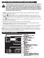
1
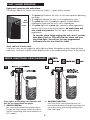
IRON SOFT PLUS™ SERIES
Water Conditioners
Installation Instructions & Owner’s Manual
CAUTION: The manufacturer does not recommend the use of any
resin cleaners. Please refer to page 6 in this manual or the warning
label on the back of the brine tank.
TABLE OF CONTENTS:
Installation Instructions
Page 3-4
Start-up Procedures
Page 5-6
Programming the Iron Soft Plus Timer
Page 6-8
Light/Alarm Operation
Page 9
Water Conditioner Flow Diagrams
Page 9-10
Troubleshooting
Page 11-12
Parts & Assembly Diagrams
Page 13-18
Blank
Page 19
Capacity & Physical Specifications
Page 20
YOUR WATER TEST
Hardness
Iron
pH
*Nitrates
Manganese
Sulphur
Total Dissolved Solids
gpg
ppm
number
ppm
ppm
yes/no
*Over 10 ppm may be harmful for human consumption. Water
conditioners do not remove nitrates or coliform bacteria, this
requires specialized equipment.
Your Iron Soft Plus Series water conditioners are precision built, high quality products. These units will deliver
conditioned water for many years to come, when installed and operated properly. Please study this manual
carefully and understand the cautions and notes before installing. This manual should be kept for future
reference. If you have any questions regarding your water conditioner, contact your local dealer.
PRE-INSTALLATION INSTRUCTIONS:
Although the Iron Soft Plus Series Water Conditioner is shipped complete, some assembly may be required.
1. After unboxing the unit, please note that on most models the control valve is installed on the tank. If not,
remove “split flange” from control valve adapter base, remove cardboard tank shim. Inspect “O” Ring on
top of flange and grease with silicone provided. Place valve (shipped in a separate box) on adapter base.
The valve is “keyed” and will only attach one way. Using split flange, attach control valve to tank.
CAUTION: The “split flange” should secure the valve with the top of the flange
facing up. Please note “top” on the split flange.
2. Install the chlorine generator on the brine valve (Fig. 3) by inserting 3/8" tube and tightening the
nut. Plug generator’s electrical end into receiving adapter from the back plate. Do not install brine
line at this time.
CAUTION: Never grab onto the generator to move unit. This will result in
cracking the valve body.
3. Install meter and bypass, if ordered, (Fig. 3) using silicone grease provided on “O” Rings.
Extra “O” Rings have also been provided in case a tear occurs during installation.
NOTE: Meter should be installed between the control valve and the bypass with the meter
“turbine” being installed on the outlet side of the control valve (Fig.3).
4. Secure both the meter and the bypass using the clips provided.
NOTE: There will be some up and down “play” and should not be of concern since
the “O” Rings will seal and no leaks should occur.
INSTALLATION INSTRUCTIONS:
IMPORTANT: In the following installation instructions various types of plumbing pipe are recommended.
These types may or may not be approved for your local plumbing codes. All plumbing must be installed
according to local plumbing codes.
1. A selection site should be chosen for your conditioner. If you have a well system, this would be
after the pressure tank but before the hot water heater (Fig. 1). If you have city water, install the
softener on the inlet line to the building before the hot water heater (Fig. 2).
NOTE: Try to locate the softener as close to a drain (floor drain, sump pump, etc.) as possible.
WELL WATER INSTALLATION
MUNICIPAL INSTALLATION
Figure 1
Figure 2
3
2. Notice on the casting, the inlet and outlet
markings, make sure the incoming water is
plumbed to the inlet and outlet is plumbed to
service (Fig. 3). Your water softener must be
installed with a bypass valve. If your conditioner is
not equipped with one, make a provision in the
plumbing system for a bypass to be installed.
IMPORTANT: Make sure the water is turned
off and pressure is released before a cut is made
into plumbing system. At this time you should
also make provisions for hard water lines to
outside tap and anywhere else desired.
TOP VIEW
3. To “bypass” your water conditioner, turn valves
A & B to the bypass open position (Fig. 3.). This
will supply unconditioned water to the house.
4. Check local plumbing code for approved piping.
The size diameter of pipe should be equal to the size
opening of the casting or larger.
Figure 3
5. In the brine tank there is a piece of flexible brine tube.
This tube runs from the brine flow control assembly (in the
brine tank, Fig. 4) to the chlorine generator, located on the
control head. Remove chlorine generator from valve and
insert tubing into generator, fitting firmly; pull on tubing
making sure it is secure. Do not attach other end to the
brine tank, as this will be covered in start-up procedures.
Reattach generator to valve, making sure clip is secure.
NOTE: Brine line should go into elbow
approximately 3/4".
6. The drain line must be connected from the drain line
flow control (Fig. 4), to a floor drain, sump pump, etc.
This pipe is not provided with your water conditioner
and is the responsibility of the installer. Check your local
plumbing code for approved piping. In any case, it should
be of adequate inside diameter to allow for proper
drainage. Secure pipe to flow control and run to drain.
Figure 4
CAUTION: Make sure the drain, drain control and clip are attached securely to
the control valve before start up.
IMPORTANT: A 2" air gap is required on the drain line.
7. Notice the elbow protruding from the brine tank. It is recommended to run a line from this elbow to
the drain. This is a precautionary step in case of brine tank overflow. A separate line should be run.
CAUTION: Never connect the brine tank overflow line and drain line together;
however, the same drain may be used.
4
START-UP PROCEDURES FOR ELECTRONIC CONTROLLER:
•
•
•
•
After installation is complete, rotate bypass handles to bypass mode (see “Valves Closed” in Fig.3).
Turn on water and check for leaks.
Fully open a cold water faucet — preferably a laundry sink or bathtub with no aerator.
Allow water to run until clear to rid pipes of debris which may have occurred during installation.
NOTE: The system regeneration sequence for the Iron Soft Plus Conditioner.
Backwash
Regenerate (Brine)
Rapid Rinse
Fill
Service
The system is now ready for filling with water. For the purpose of filling the softener, leave the unit
in the bypass position until the 2nd step, then repeat steps 1-6 with the unit full. Do not open the
bypass at this time, it will be filled in the backwash position. Once the unit is filled with water
(step 2), then open the bypass.
1. With the softener in the bypass mode (“Bypass valve,” Fig. 3) and the control valve in normal
operation where the display shows either the time of day or the gallons remaining:
Manually add 5 GALLONS of water to the regenerant tank.
NOTE: If too much water is put into the brine tank during softener startup, it could result in a salty
water complaint after the first regeneration.
During the first regeneration the unit will draw out the initial volume of brine/regenerant and refill
it with the correct preset amount.
2. Press and hold the
button for 5 seconds.
NOTE: You will hear a click, indicating the valve will go into regeneration. There is a 10-second
delay until the motor starts to advance, the unit is now in the backwash position. Once motor has
stopped, open inlet handle (“Valve B,” Fig. 3) of the bypass valve very slightly allowing water to
fill the tank slowly in order to expel air. Once air is expelled and water is running at drain, open
inlet to control.
CAUTION: If water flows too rapidly it could result in loss of media to the
drain. When the water is flowing steadily to the drain without the presence
of air, slowly open the inlet valve. Check that the drain can receive the flow
of water. Restore power.
3. Connect brine line to brine tank. Press
button again to put the valve into BRINE position.
Display will flash No. 2 until position is reached. Check the brine line for section. Verify that water is
being drawn from regenerant tank with no air leaks or bubbles in the brine line. There should be a
slow flow to the drain.
4. Press
button and place unit into rinse position. Display will flash No.3 until position is reached.
Check drain line to be secure and see that drain can receive the flow of water. There should be a rapid
flow to the drain. Unplug transformer to keep the valve in the RINSE position. Allow to run until clear
and without air. While the unit is rinsing, load the brine tank with water softener salt.
5
START-UP PROCEDURES FOR ELECTRONIC CONTROLLER CONT’D:
CAUTION: Damage or destruction to the media may occur if salts containing additives
are used with the Iron Soft Plus models. Most “solar” and/or “block” salts do not
contain additives detrimental to this unit. If unsure, please check with manufacturer.
Many “pellet” or “cube” type salts are formulated with cleaning agents or additives
which can cause harm to the media. Salt manufacturers do not always list additives in
their products. Please check with salt manufacturers for any cleaning agents, binders
or phosphate material added to salt.
NOTE: The manufacturer does recommend the brine tank be cleaned once a year to discard
accumulated dirt from the salt.
5. Press the
button and place unit into the brine tank fill position. Check to verify that the
regenerant tank is filling at a rate of 1/2 gallon per minute. Check Brine line connections for leaks.
NOTE: See page 18, Safety Float Assembly, Item No. 2, for location of 1/2 gpm Refill Flow Control.
6. Press
button again, valve will cycle back to the normal operating position with the time of day
and gallons remaining displayed.
7. Repeat steps 1-6 and now check the various cycles for proper operation.
8. Once the cycle operation has been verified, place bypass valve in the normal operating mode
(“Valves Open,” Fig. 3) by opening the outlet bypass handle.
9. Go to laundry tub or bathtub faucet, preferably a faucet without an aerator, and turn on the cold water,
let the water run. Note the color of water coming from faucet. If discolored let water run until clear.
NOTE: At no time should there be “large particles” of media noticed at faucet or laundry tub. If this
is seen, immediately shut off water and bypass system as this could be an indication of a distributor
failure. Contact manufacturer or distributor for assistance.
TIMER DISPLAY DESCRIPTION:
6
TIMER OPERATION:
Set Time of Day
When the timer is In Service, push either the Set Up or Set Down button once to adjust the Time
of Day by one digit. Push and hold to adjust by several digits.
Manually Initiating a Regeneration
1. When timer is In Service, press the Extra Cycle button for five seconds to force a manual regeneration.
NOTE: You will hear a click, indicating the valve will go into regeneration. There is a 10-second
delay until the motor starts to advance.
2.
3.
4.
5.
6.
7.
The timer reaches Regeneration Cycle Step #1.
Press the Extra Cycle button once to advance valve to Regeneration Cycle Step #2
Press the Extra Cycle button once to advance valve to Regeneration Cycle Step #3
Press the Extra Cycle button once to advance valve to Regeneration Cycle Step #4
Press the Extra Cycle button once to advance valve to Regeneration Cycle Step #5
Press the Extra Cycle button once more to advance the valve back to In Service
(if
(if
(if
(if
active).
active).
active).
active).
Timer Operation During Regeneration
In the Regeneration Cycle step display, the timer shows the current regeneration step number the
valve is advancing to, or has reached, and the time remaining in that step. The step number that
displays flashes until the valve completes driving to this regeneration step position. Once all
regeneration steps are complete, the timer returns to In Service and resumes normal operation.
Example:
Less than 10 Minutes Remaining
in Regen Step #1
Press the Extra Cycle button during a Regeneration Cycle
to immediately advance the valve to the next cycle step
position and resume normal step timing.
Start a Regeneration Tonight
With metered delayed timers, press the Extra Cycle button momentarily. The In Service indicator
dot flashes and starts a Regeneration tonight at the programmed Regeneration Time.
Day Regeneration Timer
During normal operation the Time of Day display is visible at all times. The timer operates normally
until the number of days since the last regeneration reaches the Regeneration Day Override setting.
Once this occurs, a regeneration cycle is initiated at the preset Regeneration Time.
Flow Meter Equipped Timer
During normal operation the Time of Day display alternates with the Volume Remaining display
(gallons or m3).
— As treated water is used, the Volume Remaining display counts down from the calculated
system capacity to zero or (----). When this occurs a Regeneration Cycle begins or delays
to the set Regeneration Time.
— Water flow through the valve is indicated by the Flow Dot that flashes in a direct relationship
to flow rate.
7
PROGRAMMING THE ELECTRONIC CONTROLLER:
1. Enter 3200NT Programming Mode
Press and hold both the Set Up and Set Down buttons for five (5)
seconds to enter Programming Mode. When the program mode is
entered, the program light illuminates.
2. Set Feed Water Hardness
The feed water hardness setting displays only if the Regeneration
Type is set to Meter Immediate or Meter Delayed.
— Press the Set Up and Set Down buttons to set the amount
of feed water hardness (in grains/gallon). The system
automatically calculates treated water capacity based
on the feed water hardness and the system capacity.
— Press the Extra Cycle button to proceed to the next step.
3. Set Regeneration Time
A non-flashing colon between two sets of numbers identifies the
Regeneration Time display. Set the desired time of day that you
want Regeneration to occur.
— Press the Set Up and Set Down buttons to adjust this value.
— Press the Extra Cycle button to proceed to the next step.
4. Set Regeneration Day Override
Use this display to set the maximum amount of time (in days) the
unit can be In Service without a Regeneration.
NOTE: The manufacturer has preset this to every 6 days.
— For System 4 Time Clock regeneration mode, the system
regenerates at the time set in Step 4 after the number of
days programmed in this step.
— For all other System Types (4 Meter Immediate, 4 Meter
Delayed, 5, 6, 7, 9), the system regenerates after the number
of days programmed in this step unless the meter initiates a
Regeneration cycle earlier.
— Press the Extra Cycle button to proceed to the next step.
Timer programming is complete and exits from the
Programming Mode. Normal operation resumes.
8
LIGHT /ALARM OPERATION:
Light panel operation with audio alarm:
On the right side of the control valve there are 3 lights — green, yellow and red.
Red
Yellow
Green
1. The green light indicates the unit is in the service position delivering
soft water.
2. The red light indicates the unit is in the regeneration cycle.
3. The yellow light with the red light indicates a failed chlorine
regeneration signal and the unit is still in regeneration.
4. The yellow light with a green light indicates a failed regeneration
and the unit is now in the service position. An audio alarm will
also sound every minute. This will signal a failed chlorine
regeneration.
To stop the alarm simply unplug the unit, wait 5 seconds,
then plug it back in. This will clear the alarm and clear
the yellow light. You will not lose any programmed
information on the Iron Soft Plus timer.
Check salt level in brine tank:
If salt level is low this will trigger the yellow light and alarm. Remember to always keep salt above
water level. If salt level is good, contact dealer or refer to the troubleshooting section in this manual.
WATER CONDITIONER FLOW DIAGRAMS:
2
1
Green light is on indicating service position and
that the last regeneration was proper.
1. SERVICE POSITION:
Raw water enters control head and flows down
through the Zeolite mineral, removing hardness
and iron (neutralizing acidic water conditions on
ISP-1 models).
2. BACKWASH POSITION:
Raw water enters control head and flows into
lower distributor upward through mineral bed and
out to drain, lifting and cleaning turbid particles
from Zeolite bed.
9
WATER CONDITIONER FLOW DIAGRAMS:
3a
3b
3a. BRINE RINSE POSITION:
Raw water enters control head flowing through
the injector, drawing brine from the brine tank.
Microprocessor turns on the chlorine generator
allowing brine and chlorine to flow through the
Zeolite mineral, sanitizing and regenerating the
water conditioner.
3b. SLOW RINSE POSITION:
Chlorine generator is turned off, raw water enters
control head and flows down through the Zeolite
mineral, rinsing chlorine and brine to drain.
5
4
4. RAPID RINSE POSITION:
Chlorine generator is off. Raw water enters
control head and flows down through the Zeolite
mineral, rinsing any excess brine to drain.
5. BRINE TANK FILL POSITION:
Water enters control head to self-clean injector
while flowing back to refill the brine tank. Unit
will deliver soft water in this position.
10
TROUBLESHOOTING GUIDE:
PROBLEM
CAUSE
CORRECTION
A. electrical service to unit has been
interrupted
1. Softener fails
B. timer is defective
to regenerate
2. Hard water
C. power failure
C. reset time of day
D. timer programming bad
D. check programming and reset
A. bypass valve is open
A. close bypass valve
B. no salt in brine tank
B. add salt to brine tank and maintain
salt level above water level
C. injector screen plugged
C. clean injector screen
D. insufficient water flowing into
brine tank
D. check brine tank fill time and clean
brine line flow control if plugged
E. hot water tank hardness
E. repeated flushing of the hot water
tank as required
F. leak at distributor tube
F. make sure distributor tube is not
cracked, check “O” Ring and tube pilot
G. internal valve leak
G. replace seals and spacers and/or
piston
H. flow meter jammed
H. remove obstruction from meter
I. flow meter cable disconnected
J. improper programming
A. improper salt setting
3. Unit used too
B. excessive water in brine tank
much salt
4. Loss of water
pressure
5. Loss of
mineral
through
drain line
A. assure permanent electrical service
(check fuse, plug, pull chain or
switch)
B. replace timer
I. check meter cable connection to
timer and meter
J. reprogram the control for proper
regeneration type, inlet hardness,
capacity or flow meter size
A. check salt usage and salt setting
B. see problem no. 7
C. improper programming
C. check programming, reset
A. iron buildup in line to water
conditioner
A. clean line to water conditioner
B. iron buildup in water conditioner
B. clean control head and increase
frequency of regeneration
C. inlet of control plugged due to
foreign material broken loose
from pipes
C. remove piston and clean
control head
A. air in water system
B. drain line flow control too large
11
A. assure that well system has proper
air eliminator control — check for
dry well condition
B. check flow control —
change if needed
PROBLEM
6. Iron in
conditioned
water
7. Excessive
water in
brine tank
CAUSE
CORRECTION
A. fouled mineral bed
A. check backwash, brine draw and
brine tank fill — increase frequency
of regeneration
A. plugged drain line flow control
A. clean flow control
B. brine valve failure
B. replace brine valve
C. improper programming
C. check program — reset
D. replace complete safety float
assembly
D. faulty air check or safety float
A. plugged drain line flow control
A. clean flow control
B. plugged injector system
B. clean injector and screen
C. timer not cycling
C. replace timer
8. Salty water in
D. foreign material in brine valve
service lines
D. replace brine valve seat and
clean valve
E. foreign material in brine line
flow control
E. clean brine line flow control
F. low water pressure
F. raise water pressure
A. drain line flow control is plugged
A. clean drain line flow control
B. clean injector and port behind
injector
C. clean screen
B. injector is plugged
C. injector screen plugged
9. Softener fails
to draw brine D. line pressure is too low
—
E. internal control leak
Yellow Light
F. improper programming
Indication
D. increase line pressure to 25 psi
E. change seals, spacers and piston
assembly
F. check programming — reset
G. probes scaled in chlorine generator
G. clean or replace chlorine generator
H. drawing air during regeneration
H. check brine line connections
I. electrical malfunction
I. replace board or wire harness
10. Control
A. broken or shorted micro-switch
cycles
continuously B. faulty cam operation
A. determine if switch or timer is
faulty and replace
B. replace or reinstall cam
C. internal control leak
A. check time program and
positioning of control
B. remove power head assembly
and inspect bore, remove foreign
material and check control in
various regeneration positions
C. replace seals and piston assembly
D. drive motor jammed in
regeneration
D. replace seals and piston, drive
motor, check for broken gears
A. valve not programming correctly
11. Drain flows B. foreign material in control head
continuously
12
REPLACEMENT PARTS:
PLASTIC BYPASS ASSEMBLY
Item No.
Part No.
1
2
3
4A
4B
FP9452K83
FP13255
FP13314
FP18706
FP13708
FP13708-40
FP13708-45
FP18706-02
FP41027-01
FP41026-01
FP19620-01
FP40636
Description
O-ring - 119
Mounting clip
Screw, hex washer head, 8-18x5/8
Yoke, plastic 1” NPT
Yoke, 3/4” brass
Yoke, 1” sweat
Yoke, 3/4” sweat
Yoke, 3/4” NPT plastic
Yoke, stainless 3/4” NPT
Yoke, stainless 1” NPT
Yoke assembly, 3/4”, right angle, 90°
Yoke, 1-1/4” NPT brass
ASSEMBLY
FP60049
ELECTRONIC METER ASSEMBLY
Item No.
Part No.
1
2
3
4
5
FP13314
FP19569
FP19797
FP9452K83
FP19791-01
Description
Screw, hex washer, 8-18 x 5/8”
Flow meter clip
Meter body assembly, 3/4” turbin
O-ring meter body
Flow meter harness assembly
13
Plastic bypass assembly
REPLACEMENT PARTS:
14
REPLACEMENT PARTS:
CONTROL VALVE ASSEMBLY
Item No.
Part No.
1
FP19328
2510 valve body 1"
FP12090
3.5 GPM DLFC button
2
FP10757
End spacer
FP12091
4.0 GPM DLFC button
3
FP10545
Seal ring
FP12092
5.0 GPM DLFC button
4
FP11451
Spacer
FP12408
7.0 GPM DLFC button
5
FP15168
Piston
FP12087
2.0 GPM DLFC button
6
FP14309
Piston rod retainer
FP17814
6.0 GPM DLFC button
7
FP14452
Piston rod
21
FP11183
DLFC seal o-ring
8
FP10209
Seal quad ring
22
FP60705-00
9
FP40078
Seal o-ring end plug
23
FP12338
1/2" DLFC drain fitting
10
FP10598
End plug
24
FP19936
Base seal
11
FP14805
Injector body gasket
25
FP19322
2510 adapter base
12
FP17776
Injector body plastic
26
FP19197
Slip ring
13
FP10227
Injector screen
27
FP18303
Tank o-ring
14
FP10914-1
Injector throat #1 white
28
FP13304
Distributor o-ring
FP10914-2
Injector throat #2 blue
29
FP13030
Distributor o-ring retainer
FP10914-3
Injector throat #3 yellow
30
FP60503
2510 clamp assembly
FP10914-4
Injector throat #4 green
31
FP19998
Clamp pivot
FP10913-1
Injector nozzle #1 white
32
FP40057
Clamp screw
FP10913-2
Injector nozzle #2 blue
FP10913-3
Injector nozzle #3 yellow
FP10913-4
Injector nozzle #4 green
15
Description
Item No.
Part No.
Description
Flow control housing
16
FP10229
Injector cover gasket
101
FP60011-090
17
FP11893
Injector cover
102
CV100-1A
#1 injector replacement kit
18
FP10692
Injector cover screw
CV100-2A
#2 injector replacement kit
19
FP18312
DLFC retainer clip
CV100-3A
#3 injector replacement kit
20
FP12085
1.2 GPM DLFC button
CV100-4A
#4 injector replacement kit
FP12086
1.5 GPM DLFC button
103
FP60121
Ring & seal replacement kit
FP12088
2.4 GPM DLFC button
104
FP60090
Piston assembly kit
FP12089
3.0 GPM DLFC button
105
FP10598
End plug replacement kit
15
Brine valve assembly
REPLACEMENT PARTS:
16
REPLACEMENT PARTS:
POWER HEAD ASSEMBLY
No.
Part No.
1
FP40264
Back plate
Description
2
FP17967
Fitting, liquid tight
3
FP17845-02
4
FP10300
Screw
5
FP41062
3200NT timer assembly
6
FP60219-02
7
FP15742
Screw cover
8
FP12576
Cam, drive STF518
9
FP10909
Pin, cam
10
FP14923
Screw, switch
11
FP10302
Insulator
12
FP10218
Microswitch
13
FP10231
Screw, motor bracket
14
FP41544
Motor, 110V 60 Hz
15
FP12777
Cam, brine cam
16
FP10338
Pin, roll
17
FP19849
Screw, switch
18
FP13547
Cord strain relief
19
FP40941
Drive wire harness
20
FP10896
Microswitch
Pin, hinge
Cover assembly, black w/ clear window
17
REPLACEMENT PARTS:
CHLORINATOR BOARD ASSEMBLY
SAFETY FLOAT ASSEMBLY
Item No.
Part No.
Description
1
2
3
4
5
6
7
CH4650-01
CH4655
CH4615
CH4640-32
CH4500-48
CH4600
CH4600-50
100
CH4700-27WR-1
.5 GPM safety float a/c assembly
CG21840CB1C00
BS-17A
CH1018
CH1030-34.5
CH7016
CG2191-81
18 x 40 black brine tank
3/8" brine line 6' assembly
2 piece overflow set
Brine well 4"
Brine well cap
Brine tank cover
474 safety elbow 3/8"
474 .5 GPM flow control
Elbow locking clip
474 float assembly 32" w/ grommets
474 aircheck assembly 1/2" x 48"
474 safety brine valve w/ 3/8" elbow
474 safety brine valve .5 GPM
18
Item No.
Part No.
1
FP40154-01
2
FP42038
3
WR00020LF
4
WR00040
5
WR00030CA
Description
Harness, 2510 chlorinator
Bracket, circuit board, wtr rght
Chlorinator circuit board
24V dual transformer
Chlorine generator
K
N
A
BL
19
CAPACITY
&
PHYSICAL SPECIFICATIONS:
MODEL
Capacity:
(Grains/Lbs. NaCI)
1
Maximum
Medium
Minimum
Amount of Media (Cu. Ft.)
Maximum Water Hardness (GPG)
2
Maximum Iron (PPM)
3
Minimum pH Required
4
Total pH Adjusted Water at Continuous Flows
5
Peak Flow Rate (GPM @ P-PSI)
Continuous Flow Rate (GPM @ P-PSI)
Water Pressure Range (PSI)
Water Temp. (ºF)
Electrical Requirements (volts-hertz)
Pipe Size
Total Dimensions:
Media Tank
Brine Tank
1
2
ISP1-1044
ISP1-1054
ISP1-1354
ISP2-1044
ISP2-1054
ISP2-1354
11,800 @ 12.4
11,400 @ 9.3
7,300 @ 3.2
1.0
20
8.0
6.5
630
19 @ 15.0
9.0 @ 5.0
25-100
33-100
110-50/60
1"
10"W x 52"H
18"W x 40"H
22,600 @ 15.9
20,700 @ 12.4
16,400 @ 6.1
1.5
30
10.0
6.0
252
17 @ 15.0
8.0 @ 5.0
25-100
33-100
110-50/60
1"
10"W x 62"H
18"W x 40"H
36,900 @ 21.2
33,600 @ 15.9
28,300 @ 9.5
2.5
40
15.0
6.0
432
19 @ 15.0
9.0 @ 5.0
25-100
33-100
110-50/60
1"
13"W x 62"H
18"W x 40"H
20,300 @ 12.4
19,100 @ 9.3
11,100 @ 3.2
1.0
40
8.0
7.0
NA
19 @ 15.0
9.0 @ 5.0
25-100
33-100
110-50/60
1"
10"W x 52"H
18"W x 40"H
34,800@ 15.9
32,000 @ 12.4
22,900 @ 6.1
1.5
60
10.0
7.0
NA
17 @ 15.0
8.0 @ 5.0
25-100
33-100
110-50/60
1"
10"W x 62"H
18"W x 40"H
60,300 @ 26.5
48,300 @ 15.9
28,200 @ 9.3
2.5
80
15.0
7.0
NA
19 @ 15.0
9.0 @ 5.0
25-100
33-100
110-50/60
1"
13"W x 62"H
18"W x 40"H
All ISP Water Conditioners are pre-factory set at medium salting. Note: influent waters must be at
least 3 GPG hardness and 80 TDS. A calcite or corsex unit may be needed for correct operation.
Iron removal may vary depending on form of iron, pH and other local conditions. On waters
that are pre-chlorinated or where other pre-oxidation occurs, an iron precipitate can form
that is too small to be filtered.
3
The pH listed is the minimum for the influent water.
4
This is the minimum number of gallons at the continuous flow rate corrected
to a 7 pH.The actual amount of pH adjusted water may be greater.
5
Unit not tested for capacity at these flow rates. Water quality may vary.
Height
Width
Length
Manufactured by Water-Right, Inc. • 1900 Prospect Court • Appleton, WI 54914 • Phone: 920-739-9401 • Fax: 920-739-9406
LIT-ISP Manual 250