1
Agilent 75000 Series B
Agilent E1343A, E1344A, E1345A, E1347A,
E1355A and E1356A
Relay Multiplexers
Service Manual
Copyright © Agilent Technologies, Inc. 2005
Printed in Malaysia
Contents
E1343A/44A/45A/47A/55A/56A Service Manual
Warranty . . . . . . . . . .
Safety Symbols . . . . . .
WARNINGS . . . . . . . .
Declaration of Conformity .
Reader Comment Sheet . .
Manual Overview . . . . .
Manual Content . . . . . .
.
.
.
.
.
.
.
.
.
.
.
.
.
.
.
.
.
.
.
.
.
.
.
.
.
.
.
.
.
.
.
.
.
.
.
.
.
.
.
.
.
.
.
.
.
.
.
.
.
.
.
.
.
.
.
.
.
.
.
.
.
.
.
.
.
.
.
.
.
.
.
.
.
.
.
.
.
.
.
.
.
.
.
.
.
.
.
.
.
.
.
.
.
.
.
.
.
.
.
.
.
.
.
.
.
.
.
.
.
.
.
.
.
.
.
.
.
.
.
.
.
.
.
.
.
.
.
.
.
.
.
.
.
.
.
.
.
.
.
.
.
.
.
.
.
.
.
.
.
.
.
.
.
.
.
.
.
.
.
.
.
.
.
.
.
.
.
.
.
.
.
.
.
.
.
.
.
.
.
.
.
.
.
.
.
.
.
.
.
.
.
.
.
.
.
.
.
.
.
.
.
.
.
.
.
.
.
.
.
.
.
.
.
.
.
.
.
.
.
.
.
.
.
.
3
4
4
5
7
9
9
Chapter 1. General Information . . . . . . . . . . . . . . . . . . . . . . . . . . . . . . . . 11
Introduction . . . . . . . . . . . . . . . . . .
Safety Considerations . . . . . . . . . . . . .
WARNINGS . . . . . . . . . . . . . . . .
CAUTIONS . . . . . . . . . . . . . . . .
Relay Life . . . . . . . . . . . . . . . . . . .
Loading and Switching Frequency Effects .
End-of-Life Detection . . . . . . . . . . .
Replacement Strategy . . . . . . . . . . .
Multiplexer Descriptions . . . . . . . . . . .
E1343A/44A Descriptions . . . . . . . . .
E1345A/47A Descriptions . . . . . . . . .
E1355A/56A Descriptions . . . . . . . . .
Multiplexer Specifications . . . . . . . . .
Multiplexer Environment . . . . . . . . . .
Multiplexer Serial Numbers . . . . . . . .
Multiplexer Options . . . . . . . . . . . .
Schematics and Component Locators . . .
Recommended Test Equipment . . . . . . . .
Inspection/Shipping . . . . . . . . . . . . . .
Initial Inspection . . . . . . . . . . . . . .
Shipping Guidelines . . . . . . . . . . . .
.
.
.
.
.
.
.
.
.
.
.
.
.
.
.
.
.
.
.
.
.
.
.
.
.
.
.
.
.
.
.
.
.
.
.
.
.
.
.
.
.
.
.
.
.
.
.
.
.
.
.
.
.
.
.
.
.
.
.
.
.
.
.
.
.
.
.
.
.
.
.
.
.
.
.
.
.
.
.
.
.
.
.
.
.
.
.
.
.
.
.
.
.
.
.
.
.
.
.
.
.
.
.
.
.
.
.
.
.
.
.
.
.
.
.
.
.
.
.
.
.
.
.
.
.
.
.
.
.
.
.
.
.
.
.
.
.
.
.
.
.
.
.
.
.
.
.
.
.
.
.
.
.
.
.
.
.
.
.
.
.
.
.
.
.
.
.
.
.
.
.
.
.
.
.
.
.
.
.
.
.
.
.
.
.
.
.
.
.
.
.
.
.
.
.
.
.
.
.
.
.
.
.
.
.
.
.
.
.
.
.
.
.
.
.
.
.
.
.
.
.
.
.
.
.
.
.
.
.
.
.
.
.
.
.
.
.
.
.
.
.
.
.
.
.
.
.
.
.
.
.
.
.
.
.
.
.
.
.
.
.
.
.
.
.
.
.
.
.
.
.
.
.
.
.
.
.
.
.
.
.
.
.
.
.
.
.
.
.
.
.
.
.
.
.
.
.
.
.
.
.
.
.
.
.
.
.
.
.
.
.
.
.
.
.
.
.
.
.
.
.
.
.
.
.
.
.
.
.
.
.
.
.
.
.
.
.
.
.
.
.
.
.
.
.
.
.
.
.
.
.
.
.
.
.
.
.
.
.
.
.
.
.
.
.
.
.
.
.
.
.
.
.
.
.
.
.
.
.
.
.
.
.
.
.
.
.
.
.
.
.
.
.
.
.
.
.
.
.
.
.
.
.
.
.
.
.
.
.
.
.
.
.
.
.
.
.
.
.
.
.
.
.
.
.
.
.
.
.
.
.
.
.
.
.
.
.
.
.
.
.
.
.
.
.
.
.
.
.
.
.
.
.
.
.
.
.
.
.
.
.
.
11
12
12
13
14
14
14
15
15
15
15
15
16
16
16
16
16
17
17
17
19
Chapter 2. Verification Tests . . . . . . . . . . . . . . . . . . . . . . . . . . . . . . . . . . 21
Introduction . . . . . . . . . . .
Test Conditions & Procedures
Performance Test Record . . .
Verification Test Examples .
Functional Verification Test . . .
Procedure . . . . . . . . . .
Example . . . . . . . . . . .
Operation Verification Test . . .
Performance Verification Tests .
Wiring the Test Fixture . . . .
Performance Test Record . . . .
Test Limits . . . . . . . . . .
Measurement Uncertainty . .
E1343A/44A/45A/47A/55A/56A Service Manual
.
.
.
.
.
.
.
.
.
.
.
.
.
.
.
.
.
.
.
.
.
.
.
.
.
.
.
.
.
.
.
.
.
.
.
.
.
.
.
.
.
.
.
.
.
.
.
.
.
.
.
.
.
.
.
.
.
.
.
.
.
.
.
.
.
.
.
.
.
.
.
.
.
.
.
.
.
.
.
.
.
.
.
.
.
.
.
.
.
.
.
.
.
.
.
.
.
.
.
.
.
.
.
.
.
.
.
.
.
.
.
.
.
.
.
.
.
.
.
.
.
.
.
.
.
.
.
.
.
.
.
.
.
.
.
.
.
.
.
.
.
.
.
.
.
.
.
.
.
.
.
.
.
.
.
.
.
.
.
.
.
.
.
.
.
.
.
.
.
.
.
.
.
.
.
.
.
.
.
.
.
.
.
.
.
.
.
.
.
.
.
.
.
.
.
.
.
.
.
.
.
.
.
.
.
.
.
.
.
.
.
.
.
.
.
.
.
.
.
.
.
.
.
.
.
.
.
.
.
.
.
.
.
.
.
.
.
.
.
.
.
.
.
.
.
.
.
.
.
.
.
.
.
.
.
.
.
.
.
.
.
.
.
.
.
.
.
.
.
.
.
.
.
.
.
.
.
.
.
.
.
.
.
.
.
.
.
.
.
.
.
.
.
.
.
.
.
.
.
.
.
.
.
.
.
.
.
.
.
.
.
.
.
.
.
.
.
.
.
.
.
.
.
.
.
.
.
.
.
.
.
.
.
.
.
.
.
.
.
.
.
.
.
.
.
.
.
.
.
.
.
.
.
.
.
.
.
.
.
.
.
.
.
.
.
.
.
.
.
.
.
.
.
.
.
.
.
21
21
21
21
22
22
22
22
23
23
37
37
37
Contents 1
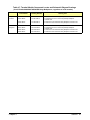
Chapter 3. Replaceable Parts . . . . . . . . . . . . . . . . . . . . . . . . . . . . . . . . . . 41
Introduction . . . . . . . . . . . . . . . . . . . . . . . . . . . . . . . . . . . . . . . . 41
Replaceable Parts List . . . . . . . . . . . . . . . . . . . . . . . . . . . . . . . . . . . 41
Parts Locators . . . . . . . . . . . . . . . . . . . . . . . . . . . . . . . . . . . . . . . 46
Chapter 4. Service . . . . . . . . . . . . . . . . . . . . . . . . . . . . . . . . . . . . . . . . 49
Introduction . . . . . . . . . . . . . . . . . . . . . . .
Equipment Required . . . . . . . . . . . . . . . . .
Service Aids . . . . . . . . . . . . . . . . . . . . .
E1343A/44A Multiplexer Descriptions . . . . . . .
E1345A/47A Multiplexer Descriptions . . . . . . .
E1355A/56A Strain Gage Multiplexer Descriptions
Troubleshooting Techniques . . . . . . . . . . . . . .
Identifying the Problem . . . . . . . . . . . . . . .
Making Visual Checks . . . . . . . . . . . . . . . .
Testing the Multiplexer . . . . . . . . . . . . . . . .
Repair and Maintenance Guidelines . . . . . . . . . . .
ESD Precautions . . . . . . . . . . . . . . . . . . .
Soldering Printed Circuit Boards . . . . . . . . . . .
Post-Repair Safety Checks . . . . . . . . . . . . . .
Component Locators and Schematic Diagrams . . . . .
.
.
.
.
.
.
.
.
.
.
.
.
.
.
.
.
.
.
.
.
.
.
.
.
.
.
.
.
.
.
.
.
.
.
.
.
.
.
.
.
.
.
.
.
.
.
.
.
.
.
.
.
.
.
.
.
.
.
.
.
.
.
.
.
.
.
.
.
.
.
.
.
.
.
.
.
.
.
.
.
.
.
.
.
.
.
.
.
.
.
.
.
.
.
.
.
.
.
.
.
.
.
.
.
.
.
.
.
.
.
.
.
.
.
.
.
.
.
.
.
.
.
.
.
.
.
.
.
.
.
.
.
.
.
.
.
.
.
.
.
.
.
.
.
.
.
.
.
.
.
.
.
.
.
.
.
.
.
.
.
.
.
.
.
.
.
.
.
.
.
.
.
.
.
.
.
.
.
.
.
.
.
.
.
.
.
.
.
.
.
.
.
.
.
.
.
.
.
.
.
.
.
.
.
.
.
.
.
.
.
.
.
.
.
.
.
.
.
.
.
.
.
.
.
.
.
.
.
.
.
.
.
.
.
.
.
.
.
.
.
.
.
.
.
.
.
.
.
.
.
.
.
.
.
.
49
49
49
50
51
53
56
56
57
58
59
59
59
59
60
Appendix A. Verification Tests - C Programs . . . . . . . . . . . . . . . . . . . . . . . . . 63
Example: Self-Test . . . . . . . . . . . . . . . . . . . . . . . . . . . . . . . . . . . 63
Example: Closed Channel Resistance Test . . . . . . . . . . . . . . . . . . . . . . 64
Example: DC Isolation Test . . . . . . . . . . . . . . . . . . . . . . . . . . . . . . 68
Appendix B. Backdating Information . . . . . . . . . . . . . . . . . . . . . . . . . . . . . 71
Introduction . . . . . . . . . . . . . . . . . . . . . . . . . . . . . . . . . . . . . . . . 71
Replaceable Parts List . . . . . . . . . . . . . . . . . . . . . . . . . . . . . . . . . . . 71
Parts Locators . . . . . . . . . . . . . . . . . . . . . . . . . . . . . . . . . . . . . . . 78
2 Contents
E1343A/44A/45A/47A/55A/56A Service Manual
Certification
Agilent Technologies, Inc. certifies that this product met its published specifications at the time of shipment from the factory. Agilent
Technologies further certifies that its calibration measurements are traceable to the United States National Institute of Standards and
Technology (formerly National Bureau of Standards), to the extent allowed by that organization’s calibration facility, and to the calibration facilities of other International Standards Organization members.
Warranty
This Agilent Technologies product is warranted against defects in materials and workmanship for a period of one year from date of
shipment. Duration and conditions of warranty for this product may be superseded when the product is integrated into (becomes a part
of) other Agilent products. During the warranty period, Agilent Technologies will, at its option, either repair or replace products which
prove to be defective.
For warranty service or repair, this product must be returned to a service facility designated by Agilent Technologies. Buyer shall prepay shipping charges to Agilent and Agilent shall pay shipping charges to return the product to Buyer. However, Buyer shall pay all
shipping charges, duties, and taxes for products returned to Agilent from another country.
Agilent warrants that its software and firmware designated by Agilent for use with a product will execute its programming instructions
when properly installed on that product. Agilent does not warrant that the operation of the product, or software, or firmware will be uninterrupted or error free.
Limitation Of Warranty
The foregoing warranty shall not apply to defects resulting from improper or inadequate maintenance by Buyer, Buyer-supplied products or interfacing, unauthorized modification or misuse, operation outside of the environmental specifications for the product, or improper site preparation or maintenance.
The design and implementation of any circuit on this product is the sole responsibility of the Buyer. Agilent does not warrant the
Buyer’s circuitry or malfunctions of Agilent products that result from the Buyer’s circuitry. In addition, Agilent does not warrant any
damage that occurs as a result of the Buyer’s circuit or any defects that result from Buyer-supplied products.
NO OTHER WARRANTY IS EXPRESSED OR IMPLIED. AGILENT TECHNOLOGIES SPECIFICALLY DISCLAIMS THE IMPLIED WARRANTIES OF MERCHANTABILITY AND FITNESS FOR A PARTICULAR PURPOSE.
Exclusive Remedies
THE REMEDIES PROVIDED HEREIN ARE BUYER’S SOLE AND EXCLUSIVE REMEDIES. AGILENT TECHNOLOGIES
SHALL NOT BE LIABLE FOR ANY DIRECT, INDIRECT, SPECIAL, INCIDENTAL, OR CONSEQUENTIAL DAMAGES,
WHETHER BASED ON CONTRACT, TORT, OR ANY OTHER LEGAL THEORY.
Notice
The information contained in this document is subject to change without notice. AGILENT TECHNOLOGIES MAKES NO WARRANTY OF ANY KIND WITH REGARD TO THIS MATERIAL, INCLUDING, BUT NOT LIMITED TO, THE IMPLIED WARRANTIES OF MERCHANTABILITY AND FITNESS FOR A PARTICULAR PURPOSE. Agilent shall not be liable for errors
contained herein or for incidental or consequential damages in connection with the furnishing, performance or use of this material.
This document contains proprietary information which is protected by copyright. All rights are reserved. No part of this document
may be photocopied, reproduced, or translated to another language without the prior written consent of Agilent Technologies, Inc.
Agilent assumes no responsibility for the use or reliability of its software on equipment that is not furnished by Agilent.
U.S. Government Restricted Rights
The Software and Documentation have been developed entirely at private expense. They are delivered and licensed as "commercial
computer software" as defined in DFARS 252.227-7013 (Oct 1988), DFARS 252.211-7015 (May 1991) or DFARS 252.227-7014
(Jun 1995), as a "commercial item" as defined in FAR 2.101(a), or as "Restricted computer software" as defined in FAR 52.227-19 (Jun
1987) (or any equivalent agency regulation or contract clause), whichever is applicable. You have only those rights provided for such Software and Documentation by the applicable FAR or DFARS clause or the Agilent standard software agreement for the product involved.
E1343A, E1344A, E1345A, E1347A, E1355A and E1356A Relay Multiplexers Service Manual
Edition 4
Copyright © 2005 Agilent Technologies, Inc. All Rights Reserved.
E1343A/44A/45A/47A/55A/56A Service Manual
3
Documentation History
All Editions and Updates of this manual and their creation date are listed below. The first Edition of the manual is Edition 1. The Edition number increments by 1 whenever the manual is revised. Updates, which are issued between Editions, contain replacement pages
to correct or add additional information to the current Edition of the manual. Whenever a new Edition is created, it will contain all of
the Update information for the previous Edition. Each new Edition or Update also includes a revised copy of this documentation history page.
Edition 1 (Part Number E1345-90011). . . . . . . . . . . . . . . . . . . . . . October 1993
Edition 2 (Part Number E1345-90012). . . . . . . . . . . . . . . . . . . . . . . . . June 1996
Edition 3 (Part Number E1345-90013). . . . . . . . . . . . . . . . . . . . . . . . . June 1997
Edition 4 (Part Number E1345-90013) . . . . . . . . . . . . . . . . . . . September 2005
Edition 4 (Part Number E1345-90013) . . . . . . . . . . . . . . . . . . September 2012
Safety Symbols
Instruction manual symbol affixed to product. Indicates that the user must refer to the
manual for specific WARNING or CAUTION information to avoid personal injury
or damage to the product.
Indicates the field wiring terminal that must
be connected to earth ground before operating the equipment—protects against electrical shock in case of fault.
or
Frame or chassis ground terminal—typically connects to the equipment’s metal
frame.
Alternating current (AC).
Direct current (DC).
Indicates hazardous voltages.
WARNING
Calls attention to a procedure, practice, or
condition that could cause bodily injury or
death.
CAUTION
Calls attention to a procedure, practice, or condition that could possibly cause damage to
equipment or permanent loss of data.
WARNINGS
The following general safety precautions must be observed during all phases of operation, service, and repair of this product.
Failure to comply with these precautions or with specific warnings elsewhere in this manual violates safety standards of design,
manufacture, and intended use of the product. Agilent Technologies, Inc. assumes no liability for the customer’s failure to
comply with these requirements.
Ground the equipment: For Safety Class 1 equipment (equipment having a protective earth terminal), an uninterruptible safety earth
ground must be provided from the mains power source to the product input wiring terminals or supplied power cable.
DO NOT operate the product in an explosive atmosphere or in the presence of flammable gases or fumes.
For continued protection against fire, replace the line fuse(s) only with fuse(s) of the same voltage and current rating and type.
DO NOT use repaired fuses or short-circuited fuse holders.
Keep away from live circuits: Operating personnel must not remove equipment covers or shields. Procedures involving the removal
of covers or shields are for use by service-trained personnel only. Under certain conditions, dangerous voltages may exist even with the
equipment switched off. To avoid dangerous electrical shock, DO NOT perform procedures involving cover or shield removal unless
you are qualified to do so.
DO NOT operate damaged equipment: Whenever it is possible that the safety protection features built into this product have been impaired, either through physical damage, excessive moisture, or any other reason, REMOVE POWER and do not use the product until
safe operation can be verified by service-trained personnel. If necessary, return the product to an Agilent Technologies Sales and Service Office for service and repair to ensure that safety features are maintained.
DO NOT service or adjust alone: Do not attempt internal service or adjustment unless another person, capable of rendering first aid
and resuscitation, is present.
DO NOT substitute parts or modify equipment: Because of the danger of introducing additional hazards, do not install substitute
parts or perform any unauthorized modification to the product. Return the product to an Agilent Technologies Sales and Service Office
for service and repair to ensure that safety features are maintained.
4
E1343A/44A/45A/47A/55A/56A Service Manual
Declaration of Conformity
Declarations of Conformity for this product and for other Agilent products may be downloaded from the Internet. There are two methods to obtain
the Declaration of Conformity:
•
Go to http://regulations.corporate.agilent.com/DoC/search.htm . You can then search by product number to find the latest Declaration
of Conformity.
• Alternately, you can go to the product web page (e.g., www.agilent.com/find/E1343A), click on the Document Library tab then
scroll down until you find the Declaration of Conformity link.
Notes
6
E1343A/44A/45A/47A/55A/56A Service Manual
What’s in This Manual
Manual Overview
This manual shows how to service the E1343A, E1344A, E1345A, E1347A,
E1355A, and E1356A Relay Multiplexers. Consult the
E1343A/E1344A/E1345A/E1347A User’s Manual for additional
information on installing, configuring, and operating the E1343A, E1344A,
E1345A and E1347A. Consult the E1355A/E1356A Strain Gage
Multiplexer User’s Manual for additional information on installing,
configuring, and operating the E1355A and E1356A. Consult the
appropriate mainframe user’s manual for information on configuring and
operating the mainframe.
Manual Content
Chap
Title
Content
1
General Information
Provides a basic description and lists the test equipment required
for service.
2
Verification
Tests
Functional verification, operation verification, and
performance verification tests.
3
Replaceable
Parts
Lists replaceable parts for multiplexers as follows:
E1343A w/Serial Number 3131A00852 and higher
E1344A w/Serial Number 3131A00512 and higher
E1345A w/Serial Number 2934A07622 and higher
E1347A w/Serial Number 2934A03663 and higher
E1355A w/Serial Number 3035A00331 and higher
E1356A w/Serial Number 3035A00457 and higher.
4
Service
Procedures to aid in fault isolation and repair of the multiplexers.
Appx A
Verification Tests C Programs
Provides C Program Examples to do the Verification Tests in Chapter 2.
Appx B
Backdating
Information
Lists replaceable parts for multiplexers as follows:
E1343A w/Serial Number 2934A00001 through 3131A00851
E1344A w/Serial Number 2934A00001 through 3131A00511
E1345A w/Serial Number 2934A00001 through 2934A07621
E1347A w/Serial Number 2934A00001 through 2934A03662
E1355A w/Serial Number 2934A00001 through 3035A00330
E1356A w/Serial Number 2934A00001 through 3035A00456 .
E1343A/44A/45A/47A/55A/56A Service Manual
What’s In This Manual 9
Notes
10 What’s In This Manual
E1343A/44A/45A/47A/55A/56A Service Manual
Chapter 1
General Information
Introduction
This manual contains information required to test, troubleshoot, and repair
the following Agilent relay multiplexers:
• E1343A 16-Channel High Voltage Relay Multiplexer
• E1344A 16-Channel High Voltage & Thermocouple Compensated
•
•
•
•
Relay Multiplexer
E1345A 16-Channel Relay Multiplexer
E1347A 16-Channel Thermocouple Compensated Relay Multiplexer
E1355A 8-Channel 120-Ohm Relay Multiplexer
E1356A 8-Channel 350-Ohm Relay Multiplexer.
Refer to the respective module’s User’s Manual for information on
programming and configuring these modules.
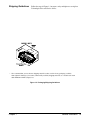
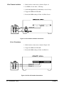
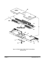
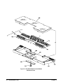
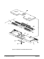
Figure 1-1 shows a typical layout for each of the relay multiplexers. Each
multiplexer consists of a component assembly and a terminal module. The
Agilent E1345A, E1347A, E1355A, and E1356A multiplexers use the same
component assembly, but each multiplexer uses a unique terminal module.
The Agilent E1343 and E1344 multiplexers use a different component
assembly.
Figure 1-1. Relay Multiplexer Assemblies
Chapter 1
General Information 11
Safety Considerations
These products are Safety Class I instruments provided with a protective
earth terminal when installed in the mainframe. Check the mainframe,
multiplexer, and all related documentation for safety markings and
instructions before operation or service.
Refer to the WARNINGS on page 4 in this manual for a summary of safety
information. Safety information for preventive maintenance, testing, and
service follows and is also found throughout this manual.
WARNINGS
WARNING
This section contains WARNINGS which must be followed for your
protection when performing equipment maintenance or repair.
SERVICE-TRAINED PERSONNEL ONLY. The information in this
manual is for service-trained personnel who are familiar with
electronic circuitry and are aware of the hazards involved. To
avoid personal injury or damage to the instrument, do not
perform procedures in this manual or do any servicing unless
you are qualified to do so.
CHECK MAINFRAME POWER SETTINGS. Before applying
power, verify that the mainframe setting matches the line
voltage and that the correct fuse is installed. An uninterruptible
safety earth ground must be provided from the main power
source to the supplied power cord set.
GROUNDING REQUIREMENTS. Interruption of the protective
(grounding) conductor (inside or outside the mainframe) or
disconnecting the protective earth terminal will cause a
potential shock hazard that could result in personal injury.
(Grounding one conductor of a two-conductor outlet is not
sufficient protection.)
IMPAIRED PROTECTION. Whenever it is likely that instrument
protection has been impaired, the mainframe must be made
inoperative and be secured against any unintended operation.
REMOVE POWER IF POSSIBLE. Some procedures in this
manual may be performed with power supplied to the
mainframe while protective covers are removed. Energy
available at many points may, if contacted, result in personal
injury. (If maintenance can be performed without power applied,
the power should be removed.)
12 General Information
Chapter 1
WARNING
USING AUTOTRANSFORMERS. If the mainframe is to be
energized via an autotransformer (for voltage reduction) make
sure the common terminal is connected to neutral (that is, the
grounded side of the main’s supply).
CAPACITOR VOLTAGES. Capacitors inside the mainframe may
remain charged even when the mainframe has been
disconnected from its source of supply.
USE PROPER FUSES. For continued protection against fire
hazard, replace the line fuses only with fuses of the same
current rating and type (such as normal blow, time delay, etc.).
Do not use repaired fuses or short-circuited fuseholders.
WIRING INSULATION. To prevent electrical shock, all wires to
the channel connections must be insulated to at least 120 V rms
(170 V peak).
CAUTIONS
CAUTION
This section contains CAUTIONS which must be followed to avoid damage
to the equipment when performing instrument maintenance or repair.
MAXIMUM VOLTAGE/CURRENT. The maximum voltage that
may be applied between High (H), Low (L), and Guard (G)
terminals is 170VDC or 120Vrms (170Vpeak) for the E1345A,
E1347A, E1355A, and E1356A modules. The maximum voltage
that may be applied between High (H), Low (L), and Guard (G)
terminals is 250VDC or ACrms (354Vpeak) for the E1343A or
E1344A. The maximum current is 50 mA (non-conductive) per
channel. The maximum power per channel is 1 VA.
STATIC ELECTRICITY. Static electricity is a major cause of
component failure. To prevent damage to the electrical
components in the multiplexers, observe anti-static techniques
whenever working on a multiplexer.
Chapter 1
General Information 13
Relay Life
Electromagnetic relays are subject to normal wear-out. Relay life depends
on several factors. Two factors are loading and switching frequency effects.
Loading and
Switching
Frequency Effects
Relay Load. In general, higher power switching reduces relay life. In
addition, capacitive/inductive loads and high inrush currents (e.g., when
turning on a lamp or motor) reduce relay life. Exceeding the specified
maximum inputs can cause catastrophic failure.
Switching Frequency. Relay contacts heat up when switched. As the
switching frequency increases, the contacts have less time to dissipate heat.
The resulting increase in contact temperature reduces relay life.
End-of-Life
Detection
A preventive maintenance routine can prevent problems caused by
unexpected relay failure. The end-of-the life of a relay can be determined
using one or more of the following methods. The best method (or
combination of methods), as well as the failure criteria, depends on the
application in which the relay is used.
Check Contact Resistance. As a relay begins to wear out, its contact
resistance will increase. When the resistance exceeds a pre-determined
value, the relay should be replaced. Typically, a relay should be replaced
when the contact resistance exceeds 2.0Ω.
Check Stability of Contact Resistance. The stability of relay contact
resistance decreases with age. Using this method, the contact resistance is
measured several (5-10) times, and the variance of the measurements is
determined. An increase in the variance indicates deteriorating performance.
Replace Relays after Defined Number of Operations. Relays can be
replaced after a predetermined number of contact closures. However, this
method requires knowledge of the applied load and life specifications for
the applied load. For the multiplexers, maximum relay life is specified to be
108 operations at no load or 107 operations at rated load.
14 General Information
Chapter 1
Replacement
Strategy
NOTE
The replacement strategy also depends on the application. If some relays are
used more often, or at higher load, than the others, the relays can be
individually replaced as needed. If all of the relays see similar loads and
switching frequencies, then replace the entire circuit board when the relay
end-of-life approaches. The sensitivity of the application should be weighed
against the cost of replacing relays with some useful life remaining.
Relays that wear out normally or fail due to misuse should not be considered
defective and are not covered by the product’s warranty.
Multiplexer Descriptions
The relay multiplexers are "instruments" in the slots of a VXIbus
mainframe. As such, a multiplexer is assigned an error queue, input and
output buffers, and a status register.
NOTE
Instruments are based on the logical addresses of the plug-in modules. Refer
to the configuration guide provided with your system for information on
setting the addresses to create an instrument.
E1343A/44A
Descriptions
Both modules provide sixteen 3-wire or eight 4-wire multiplexer channels
and can switch voltages up to 250VDC or VACrms. The E1344A provides
a thermistor reference junction on the terminal card for thermocouple
measurements. Both modules use the E1343A relay component module but
they have different terminal card assemblies.
E1345A/47A
Descriptions
The E1345A and E1347A multiplexers provide multiplexing for up to 16
channels (channels 00 through 15). Each channel has HIGH (H), LOW (L),
and GUARD (G) connections. The two multiplexers are identical, except
that the E1347A terminal card assembly adds a thermistor for temperature
measurement applications.
E1355A/56A
Descriptions
The E1355A and E1356A strain gage multiplexers (when used with a
multimeter) provide static and dynamic strain measurement capabilities.
Each multiplexer provides switching (multiplexing) for up to 8 channels
(channels 00 through 07). Each channel has HIGH (H), LOW (L), GUARD
(G), +E, -E1, and -E2 connections. The two multiplexers are identical,
except that the E1355A uses 120Ω bridge resistors, and the E1356A uses
350Ω bridge resistors.
Chapter 1
General Information 15
Multiplexer
Specifications
Multiplexer
Environment
Refer to the individual module’s User’s Manual for specifications. These
specifications are the performance standards or limits against which the
instrument may be tested.
The recommended operating environment for the relay multiplexers is:
Environment
Multiplexer Serial
Numbers
Multiplexer Options
Schematics and
Component
Locators
16 General Information
Temperature
o
o
Humidity
Operating
0 C to +55 C
<65% relative (0oC to +40oC)
Storage and
Shipment
-40oC to +75oC
<65% relative (0oC to +40oC)
Multiplexers covered by this manual are identified by a serial number prefix
listed on the title page. The serial number plate is located on the backplane
connector. If the serial number prefix of your instrument is greater than the
one listed on the title page, a Manual Update (as required) will explain how
to adapt this manual to your instrument.
There are no electrical or mechanical options available for the E1343A,
E1344A, E1345A, E1347A, E1355A, E1356A Relay Multiplexers.
Component locators and schematics for the multiplexers are packaged with
this manual. Most of them are located in the back of this manual in plastic
sleeves for convenient storage. Refer to the tables at the end of Chapter 4
for a listing of what is included and where to find it.
Chapter 1
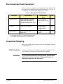
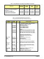
Recommended Test Equipment
Table 1-1 lists the test equipment recommended for testing, adjusting, and
servicing the relay multiplexers. Essential requirements for each piece of
test equipment are described in the Requirements column.
Table 1-1. Recommended Test Equipment
Instrument
Requirements
Recommended
Model
Use*
Controller, HP-IB
HP-IB compatibility as defined by
IEEE Standard 488-1987 and the
identical ANSI Standard MC1.1:
SH1, AH1, T2, TE0, L2, LE0, SR0,
RL0, PP0, DC0, DT0, and C1, 2, 3, 4,
5.
HP 9000 Series 300
or
IBM compatible PC with
BASIC
F,O,
P,T
Mainframe
Compatible with multiplexer
E1300A, E1301A,
E1302A or E1401B/T,
E1421B (requires
E1406A)
F,O,
P,T
Digital Multimeter
2-wire ohms (up to 1 GΩ)
4-wire ohms
3458A or
34401A
O,P,T
* F = Functional Verification, O = Operation Verification Tests,
P = Performance Verification Tests, T = Troubleshooting
Inspection/Shipping
This section contains initial (incoming) inspection and shipping guidelines
for the multiplexers.
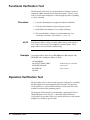
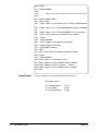
Initial Inspection
WARNING
Chapter 1
Use the steps in Figure 1-2 as guidelines to perform initial inspection of a
relay multiplexer. Performance Verification tests are optional.
To avoid possible hazardous electrical shock, do not perform
electrical tests if there are signs of shipping damage to the
shipping container or to the instrument.
General Information 17
Figure 1-2. Initial (Incoming) Inspection Guidelines
18 General Information
Chapter 1
Shipping Guidelines
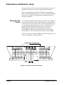
Follow the steps in Figure 1-3 to return a relay multiplexer to an Agilent
Technologies Sales and Service Office.
1. Prepare the Multiplexer
* Remove user wiring from terminal block
* Attach tag to module/pod that identifies
- Owner
- Model Number/Serial Number
- Service required
* Place tagged device in approved anti-static bag
2. Package the Multiplexer
* Place packaged multiplexer in shipping carton*
* Place 75 to 100 mm (3 to 4 inches) of shockabsorbing material around the multiplexer.
* Seal the shipping carton securely.
* Mark the shipping carton FRAGILE.
3. Ship the Multiplexer to Agilent Technologies
* Place address label on shipping carton
* Send carton to Agilent Technologies
* We recommend that you use the same shipping materials as those used in factory packaging (available
from Agilent Technologies). For other (commercially-available) shipping materials, use a double-wall carton
with minimum 2.4 MPa (350 psi) test.
Figure 1-3. Packaging/Shipping Guidelines
Chapter 1
General Information 19
Notes
20 General Information
Chapter 1
Chapter 2
Verification Tests
Introduction
This chapter describes the verification tests for the E1343A, E1344A,
E1345A, E1347A, E1355A, E1356A Relay Multiplexers. The three levels
of test procedures described in this chapter are used to verify that the
modules:
• are functional (Functional Verification Test)
• meet selected testable specifications (Operation
Verification)
• meet all testable specifications (Performance Verification)
Test Conditions &
Procedures
See Table 1-1 for test equipment requirements. You should complete the
Performance Verification tests at least once a year. For heavy use or severe
operating environments, perform the tests more often. The verification tests
assume that the person performing the tests understands how to operate the
mainframe, the multiplexers, and the specified test equipment. The test
procedures do not specify equipment settings for test equipment except in
general terms. It is assumed that a qualified, service-trained technician will
select and connect the cables, adapters, and probes required for the test.
Performance Test
Record
The results of each Performance Verification test may be recorded in
Table 2-2, "Performance Test Record," at the end of this chapter. You
may photocopy this form, if desired.
Verification Test
Examples
Each verification test procedure includes an example program that performs
the test. All example programs assume the following configuration:
•
•
•
•
•
Chapter 2
HP 9000 Series 200/300 computer
HP BASIC programming language
Multiplexer address 70914
Multiplexer card number 1
3458A Digital Multimeter (DMM)
Verification Tests 21
Functional Verification Test
The Functional Verification Test for the multiplexer modules consists of
sending the *IDN? command and checking the response. This test can be
used to verify that the multiplexer is connected properly and is responding
to a basic command.
Procedure
1. Verify that the multiplexer is properly installed in mainframe
2. Verify that the mainframe has passed its power-on test.
3. Send *IDN? to the multiplexer (see example following)
4. The return should be as follows (revision number may vary):
HEWLETT-PACKARD,SWITCHBOX,0,A.06.00
NOTE
Example
If the primary address setting, secondary address setting, or the interface
select code is set incorrectly, the multiplexer will not respond. Verify
proper address selection before troubleshooting.
An example follows which uses an HP 9000 Series 300 computer with
HP BASIC and a multiplexer address of 70914.
10 DIM A$[100]
20 OUTPUT 70914;"*IDN?"
30 ENTER 70914;A$
40 PRINT A$
50 END
!Send the ID query command
!Get response
!Print response
Operation Verification Test
The procedures in this section are used to provide a high level of confidence
that the multiplexer is meeting published specifications. The Operation
Verification Test is a subset of the Performance Verification Tests and is
suitable for checkout after performing repairs.
The Operation Verification Test is performed by completing the Closed
Channel Resistance Test (Test 2-1) as described in the Performance
Verification Test procedures. This test is usually sufficient to verify that the
multiplexer is meeting its specifications.
22 Verification Tests
Chapter 2
Performance Verification Tests
The procedures in this section are used to test the multiplexer’s electrical
performance using the specifications as the performance standards.
There are two performance verification tests for the relay multiplexers:
Test 2-1: Closed-Channel Resistance Test, and Test 2-2: DC Isolation Test.
These tests are suitable for incoming inspection, troubleshooting, and
preventive maintenance.
Wiring the Test
Fixture
A test fixture is required for the Performance Verification Tests. Figure 2-1
shows typical connections using a terminal module (aka "terminal block")
for the test fixture. You may want to order an extra terminal module to use
as a test fixture so that you don’t have to re-wire each time the tests are
performed. The E1345A terminal module may be used to test the
E1343A/45A/55A and 56A. The terminal module part number is
E1345-80001. The E1347A terminal module may be used to test the
E1344A and 47A. The terminal module part number is E1347-80001.
However, in most cases the E1345-80001 is adequate for testing any or all
of the relay multiplexer component modules.
Figure 2-1. Typical Test Fixture Connections
Chapter 2
Verification Tests 23
Test 2-1: Closed Channel Resistance Test
This test verifies that all relay contacts meet the closed-channel resistance
specification for the multiplexer. If the closed-channel resistance of any
relay contact is greater than 2Ω, the relay should be replaced. This test uses
the test fixture (see Figure 2-1).
Measuring Protection
Resistors
NOTE
Since there are 100Ω protection resistors (R20 through R31) in the relay
paths, measure the protection resistor values to begin this test. The values of
the protection resistors are then subtracted from the measured path
resistance to determine the relay contact resistance. To measure the
protection resistor values, set the 3458A DMM to 4-wire ohms, autorange
and measure each resistor value with the DMM (see Figure 2-2). Record the
measured values in Table 2-1.
On the E1343A and E1344A, Resistors R22, R25, R28, and R31 are 1.0kΩ
resistors.
Figure 2-2. Typical Resistance Measurement Connections
Table 2-1. Measured Protection Resistor Values
Resistor
Measured Value (Ω)
Resistor
Measured Value (Ω)
R20
R21
R22
___________________
___________________
___________________
R26
R27
R28
___________________
___________________
___________________
R23
R24
R25
___________________
___________________
___________________
R29
R30
R31
___________________
___________________
___________________
24 Verification Tests
Chapter 2
Chs 00 - 07 and 90
HI Measurements
1. Make Hardware Connections
– Turn mainframe power OFF
– Connect DMM leads as shown in Figure 2-3
– Turn mainframe power ON
Figure 2-3. Ch 0-7 and 90 HI Measurements Connections
2. Measure Channel 00 HI Resistance
Send *RST to multiplexer
Send CLOS (@nn00) to close chan 00, where nn = card #
Trigger the DMM with TRIG SGL and note reading
Send OPEN (@nn00) to open channel 00
Subtract measured value of R20 from DMM reading
Enter the result in Table 2-2 for Channel 00 HI
3. Repeat for Channels 01 - 07 HI and Channel 90 HI
–
–
–
–
–
–
– Repeat steps 1 and 2 for channels 01 - 07 HI and 90 HI
– Use CLOS (@nncc) and OPEN (@nncc), where nn =
card # and cc = channel # (omit leading zeroes in nn)
– For Channel 90 HI, subtract combined value of R20 + R26
Ch 00 - 07 and 90
LO Measurements
1. Make Hardware Connections
– Turn mainframe power OFF
– Connect DMM leads as shown in Figure 2-4
– Turn mainframe power ON
2. Measure Channel 00 LO Resistance
–
–
–
–
–
–
Chapter 2
Send *RST to multiplexer
Send CLOS (@nn00) to close chan 00, where nn = card #
Trigger the DMM with TRIG SGL and note reading
Send OPEN (@nn00) to open channel 00
Subtract measured value of R21 from DMM reading
Enter the result in Table 2-2 for Channel 00 LO
Verification Tests 25
Figure 2-4. Ch 0-7 and 90 LO Measurement Connections
3. Repeat for Channels 01 - 07 LO and Channel 90 LO
– Repeat steps 1 and 2 for channels 01 - 07 LO and 90 LO
– Use CLOS (@nncc) and OPEN (@nncc), where nn =
card # and cc = channel # (omit leading zeroes in nn)
– For Channel 90 LO, subtract combined value of R21 + R27
Ch 00 - 07 and 90
GU Measurements
1. Make Hardware Connections
– Turn mainframe power OFF
– Connect DMM leads as shown in Figure 2-5
– Turn mainframe power ON
Figure 2-5. Ch 00-07 and 90 GU Measurements Connections
2. Measure Channel 00 GU Resistance
–
–
–
–
–
–
26 Verification Tests
Send *RST to multiplexer
Send CLOS (@nn00) to close chan 00, where nn = card #
Trigger the DMM with TRIG SGL and note reading
Send OPEN (@nn00) to open channel 00
Subtract measured value of R22 from DMM reading
Enter the result in Table 2-2 for Channel 00 GU
Chapter 2
3. Repeat for Channels 01 - 07 GU and Channel 90 GU
– Repeat steps 1 and 2 for channels 01 - 07 GU and 90 GU
– Use CLOS (@nncc) and OPEN (@nncc), where nn =
card # and cc = channel # (omit leading zeroes in nn)
– For Channel 90 GU, subtract combined value of R22 + R28
Ch 08 - 15 and 91 - 92
HI Measurements
1. Make Hardware Connections
– Turn mainframe power OFF
– Connect DMM leads as shown in Figure 2-6
– Turn mainframe power ON
Figure 2-6. Ch 08-15 and 91-92 HI Measurements Connections
2. Measure Channel 08 HI Resistance
Send *RST to multiplexer
Send CLOS (@nn08) to close chan 08, where nn = card #
Trigger the DMM with TRIG SGL and note reading
Send OPEN (@nn08) to open channel 08
Subtract measured value of R23 from DMM reading
Enter the result in Table 2-2 for Channel 08 HI
3. Repeat for Channels 09 - 15 HI and Channels 91-92 HI
–
–
–
–
–
–
– Repeat steps 1 and 2 for channels 09 - 15 HI and 91 - 92 HI
– Use CLOS (@nncc) and OPEN (@nncc), where nn =
card # and cc = channel # (omit leading zeroes in nn)
– For Channel 91 HI, subtract combined value of R23 + R29
– For Channel 92 HI, subtract combined value of R23 + R26
Ch 08 - 15 and 91 - 92
LO Measurements
1. Make Hardware Connections
– Turn mainframe power OFF
– Connect DMM leads as shown in Figure 2-7
– Turn mainframe power ON
Chapter 2
Verification Tests 27
Figure 2-7. Chs 08-15 and 91-92 LO Measurements Connections
2. Measure Channel 08 LO Resistance
Send *RST to multiplexer
Send CLOS (@nn08) to close chan 08, where nn = card #
Trigger the DMM with TRIG SGL and note reading
Send OPEN (@nn08) to open channel 08
Subtract measured value of R24 from DMM reading
Enter the result in Table 2-2 for Channel 08 LO
3. Repeat for Channels 09 - 15 LO and Channels 91 - 92 LO
–
–
–
–
–
–
– Repeat steps 1 and 2 for channels 09 - 15 LO and 91 - 92 LO
– Use CLOS (@nncc) and OPEN (@nncc), where nn =
card # and cc = channel # (omit leading zeroes in nn)
– For Channel 91 LO, subtract combined value of R24 + R30
– For Channel 92 LO, subtract combined value of R24 + R27
Ch 08 - 15 and 91 - 92
GU Measurements
1. Make Hardware Connections
– Turn mainframe power OFF
– Connect DMM leads as shown in Figure 2-8
– Turn mainframe power ON
Figure 2-8. Chs 08-15 and 91-92 GU Measurements Connections
28 Verification Tests
Chapter 2
2. Measure Channel 08 GU Resistance
Send *RST to multiplexer
Send CLOS (@nn08) to close chan 08, where nn = card #
Trigger the DMM with TRIG SGL and note reading
Send OPEN (@nn08) to open channel 08
Subtract measured value of R25 from DMM reading
Enter the result in Table 2-2 for Channel 08 GU
3. Repeat for Channels 09 - 15 GU and Channels 91 - 92 GU
–
–
–
–
–
–
– Repeat steps 1 and 2 for channels 09 - 15 GU and 91- 92 GU
– Use CLOS (@nncc) and OPEN (@nncc), where nn =
card # and cc = channel # (omit leading zeroes in nn)
– For Channel 91 GU, subtract combined value of R25 + R31
– For Channel 92 GU, subtract combined value of R25 + R28
Example: Closed
Channel Resistance
Test
NOTE
The following program performs a Closed Channel Resistance Test on
Channels 00 - 15 and 90 - 92 HI, LO, and GU. If the contact resistance for a
channel is >2.0 Ω, the program displays the message "Resistance for
Channel chan Relay is >2.0 Ohms" and stops.
Since small measurement variations occur when measuring the protection
resistors, the program returns "0.00" if the calculated resistance is <0 Ω.
10
20
30
! RE-SAVE "CLOS_TEST"
ASSIGN @Dmm TO 722
ASSIGN @Mux TO 70914
40 DISP CHR$(129)
50 DIM R(20:31),Value0(8,2),Value1(9,2),Result0(8,2), Result1(9,2),
Path$(2)[2]
60 DATA HI,LO,GU
70 READ Path$(*)
80
!
90
100 !
!Measure protection resistors
110 PRINT "Measure Protection Resistors R20 - R31 "
120 PRINT TABXY(1,3)," 1. Turn mainframe power OFF"
130 PRINT TABXY(1,4)," 2. Remove E1345A Component Assembly
from mainframe"
140 PRINT TABXY(1,5)," 3. Set DMM for 4-wire ohms (OHMF) function
"
150 DISP " Press Continue when ready to measure protection resistors "
160 PAUSE
170 CLEAR SCREEN
180 FOR I=20 TO 31
190
PRINT TABXY(1,4),"Connect DMM leads (4-wire) to resistor R";I
Continued on Next Page
Chapter 2
Verification Tests 29
200 PRINT TABXY(1,5),"Measure resistor R";I;"value (in Ohms)"
210 INPUT " Enter resistor value (in Ohms), then press Continue ",R(I)
220 NEXT I
230
240
250
260
CLEAR SCREEN
PRINT "Install Component Assembly and Test Fixture "
PRINT
PRINT " 1. Turn Mainframe power OFF"
270
280
290
300
PRINT "
PRINT "
PRINT "
PRINT "
2. Install E1345A Component Assembly into Mainframe "
3. Attach Test Fixture to Component Assembly"
4. Turn Mainframe power ON "
5. Press Continue when ready to begin testing "
310 PAUSE
320 CLEAR SCREEN
330 !
! Measure Channels 00-07 and Channel 90 (HI, LO, and GU)
340
350 !
360 OUTPUT @Dmm;"PRESET NORM;FUNC OHMF"
370 OUTPUT @Mux;"*RST"
380 FOR K=0 TO 2
390 PRINT TABXY(1,1),"Channel 00-07 and Channel 90 ";Path$(K);"
Measurements
"
400 PRINT TABXY(1,3),"Connect DMM Sense and Input HI leads to
COMMON ";Path$(K)
410 PRINT TABXY(1,4),"Connect DMM Sense and Input LO leads to
VOLTAGE SENSE ";Path$(K)
420 DISP " Press Continue when connections are complete "
430 PAUSE
440 CLEAR SCREEN
450
460
470
480
FOR I=0 TO 8
IF I<8 THEN J=I+100
IF I=8 THEN J=190
OUTPUT @Mux;"CLOS (@"&VAL$(J)&")"
490
OUTPUT @Dmm;"TRIG SGL"
500
510
ENTER @Dmm;Value0(I,K)
OUTPUT @Mux;"OPEN (@"&VAL$(J)&")"
520
IF I<8 AND K=0 THEN Result0(I,K)=Value0(I,K)-R(20)
530
540
550
560
IF I<8 AND K=1 THEN Result0(I,K)=Value0(I,K)-R(21)
IF I<8 AND K=2 THEN Result0(I,K)=Value0(I,K)-R(22)
IF I=8 AND K=0 THEN Result0(I,K)=Value0(I,K)-(R(20)+R(26))
IF I=8 AND K=1 THEN Result0(I,K)=Value0(I,K)-(R(21)+R(27))
570
580
IF I=8 AND K=2 THEN Result0(I,K)=Value0(I,K)-(R(22)+R(28))
IF Result0(I,K)<0. THEN Result0(I,K)=0.
590
IF Result0(I,K)>2.0 THEN
Continued on Next Page
30 Verification Tests
Chapter 2
600
610
620
PRINT "Resistance for Channel";I;"Relay is >2.0 Ohms"
PAUSE
END IF
630 NEXT I
640 IF K<2 THEN
650
PRINT "Measurements complete for Channels 00 - 07 and 90
";Path$(K)
660
DISP " Press Continue for Channels 00 - 07 and 90 ";Path$(K+1);"
measurements "
670
PAUSE
680 ELSE
690
PRINT " Measurements complete for Channels 00 - 07 and 90
";Path$(K)
700
DISP " Press Continue for Channels 08 - 15 and 91-92 tests "
710
PAUSE
720 END IF
730 NEXT K
740 !
750
!Measure Channels 08-15 and Channels 91-92 (HI, LO, and GU)
760 !
770 OUTPUT @Mux;"*RST"
780 CLEAR SCREEN
790 FOR K=0 TO 2
800 PRINT TABXY(1,1),"Channels 08-15 and Channels 91-92
";Path$(K);" Measurements
"
810 PRINT TABXY(1,3),"Connect DMM Sense and Input HI leads to
COMMON ";Path$(K)
820 PRINT TABXY(1,4),"Connect DMM Sense and Input LO leads to
CURRENT SOURCE ";Path$(K)
830 DISP " Press Continue when connections are complete "
840 PAUSE
850 CLEAR SCREEN
860
870
880
890
FOR I=0 TO 9
IF I<8 THEN J=I+108
IF I=8 THEN J=191
IF I=9 THEN J=192
900
OUTPUT @Mux;"CLOS (@"&VAL$(J)&")"
910
920
OUTPUT @Dmm;"TRIG SGL"
ENTER @Dmm;Value1(I,K)
930
OUTPUT @Mux;"OPEN (@"&VAL$(J)&")"
940
950
960
970
IF I<8 AND K=0 THEN Result1(I,K)=Value1(I,K)-R(23)
IF I<8 AND K=1 THEN Result1(I,K)=Value1(I,K)-R(24)
IF I<8 AND K=2 THEN Result1(I,K)=Value1(I,K)-R(25)
IF I=8 AND K=0 THEN Result1(I,K)=Value1(I,K)-(R(23)+R(29))
980
IF I=8 AND K=1 THEN Result1(I,K)=Value1(I,K)-(R(24)+R(30))
Continued on Next Page
Chapter 2
Verification Tests 31
990
1000
1010
IF I=8 AND K=2 THEN Result1(I,K)=Value1(I,K)-(R(25)+R(31))
IF I=9 AND K=0 THEN Result1(I,K)=Value1(I,K)-(R(23)+R(26))
IF I=9 AND K=1 THEN Result1(I,K)=Value1(I,K)-(R(24)+R(27))
1020
1030
1040
1050
IF I=9 AND K=2 THEN Result1(I,K)=Value1(I,K)-(R(25)+R(28))
IF Result1(I,K)<0. THEN Result1(I,K)=0.
IF Result1(I,K)>2.0 THEN
PRINT "Resistance for Channel";I;"Relay is >2.0 Ohms"
1060
1070
1080
1090
PAUSE
END IF
NEXT I
IF K<2 THEN
1100
PRINT "Measurements complete for Channels 08 - 15 and 91 92 ";Path$(K)
1110
DISP " Press Continue for Channels 08 - 15 and 91 - 92
";Path$(K+1);" measurements "
1120
PAUSE
1130 ELSE
1140
PRINT "Measurements complete for Channels 08 - 15 and 91 92 ";Path$(K)
1150
DISP " Press Continue to display measurement results "
1160
PAUSE
1170
CLEAR SCREEN
1180 END IF
1190 NEXT K
1200 !
1210
! Display Relay Contact Resistances
1220 !
1230 Format:IMAGE 3(12X,D.2D,12X,D.2D,12X,D.2D,/)
1240 PRINT TABXY(1,1),"Channels 00-15 and 90-92 Relay Contact
Resistances "
1250 PRINT TABXY(1,3),"Channel HI (OHMS) LO (OHMS)
GU
(OHMS)"
1260 PRINT
1270 PRINT USING Format;Result0(*)
1280 FOR I=0 TO 8
1290
IF I<8 THEN PRINT TABXY(2,5+I),I
1300 IF I=8 THEN PRINT TABXY(3,13),"90"
1310 NEXT I
1320 PRINT USING Format;Result1(*)
1330 FOR J=8 TO 17
1340 IF J<16 THEN PRINT TABXY(2,J+1),J
1350 IF J=16 THEN PRINT TABXY(3,J+1),"91"
1360 IF J=17 THEN PRINT TABXY(3,J+1),"92"
1370 NEXT J
1380 END
32 Verification Tests
Chapter 2
Typical Results
Channel
HI (OHMS)
LO (OHMS)
GU (OHMS)
0
1
2
3
4
5
6
7
90
8
9
10
11
12
13
14
15
91
92
0.51
0.49
0.48
0.42
0.52
0.52
0.49
0.46
0.49
0.47
0.51
0.43
0.45
0.50
0.48
0.52
0.43
0.44
0.50
0.35
0.31
0.41
0.39
0.41
0.35
0.40
0.36
0.40
0.35
0.36
0.33
0.39
0.41
0.41
0.36
0.41
0.38
0.40
0.61
0.59
0.57
0.61
0.55
0.59
0.60
0.54
0.55
0.60
0.61
0.55
0.58
0.60
0.55
0.54
0.51
0.55
0.61
Test 2-2: DC Isolation Test
This test verifies that sufficient DC isolation exists at various points on the
multiplexer. DC Isolation is checked from HI to Chassis, HI to LO, and HI
to GU (GUARD). This test uses the test fixture (see Figure 2-1).
NOTE
Chapter 2
The DMM used should be capable of measuring at least 1 GΩ. If the DMM
indicates an overload, record the reading as >Rmax, where Rmax is the
highest resistance that the DMM can measure. For example, if the DMM is
an 3458A, a typical return for an overload is 1.E+38 and the entry in Table
2-2 should be >1.2 GΩ.
Verification Tests 33
HI to Chassis Isolation
1. Make hardware connections as shown in Figure 2-9
2. Set DMM to 2-wire ohms, 1 GΩ range
3. Send CLOS (@nn00:nn15, nn90:nn93) to close all relays
4. Trigger the DMM with TRIG SGL
5. Record the DMM reading on Table 2-2 (HI to Chassis)
Figure 2-9. HI to Chassis Isolation Connections
HI to LO Isolation
1. Make hardware connections as shown in Figure 2-10
2. Trigger the DMM with TRIG SGL
3. Record the DMM reading on Table 2-2 (HI to LO)
Figure 2-10. HI to LO Isolation Connections
34 Verification Tests
Chapter 2
HI to GU Isolation
1. Make hardware connections as shown in Figure 2-11
2. Trigger the DMM with TRIG SGL
3. Record the DMM reading on Table 2-2 (HI to GU)
Figure 2-11. HI to GU Isolation Connections
Example: DC Isolation
Test
This example performs DC Isolation Tests for HI to Chassis, HI to LO, and
HI to GU (GUARD).
10 !RE-SAVE "DC_ISOL"
20 ASSIGN @Dmm TO 722
30 ASSIGN @Mux TO 70914
40 DISP CHR$(129)
50
60
70
80
DIM Conn$(5)[10]
DATA CHASSIS, LO, GU, CHASSIS, COMMON LO, COMMON GU
READ Conn$(*)
OUTPUT @Dmm;"OHM 1E9"
90
100
110
120
PRINT "Equipment Connections "
PRINT
PRINT " 1. Turn Mainframe power OFF"
PRINT " 2. Install E1345A Component Assembly into Mainframe "
130 PRINT " 3. Attach Test Fixture to Component Assembly"
140 PRINT " 4. Turn Mainframe power ON"
150 PRINT " 5. Press Continue when ready to begin testing "
Continued on Next Page
Chapter 2
Verification Tests 35
160 PAUSE
170 CLEAR SCREEN
180 !
190
200 !
! Measure DC Isolation (HI to Chassis, HI to LO, HI to GU)
210 OUTPUT @Mux;"*RST"
220 FOR I=0 TO 2
230 PRINT TABXY(1,1),"DC Isolation HI to ";Conn$(I);" Measurements
"
240 PRINT TABXY(1,3),"1. Connect DMM INPUT HI lead to COMMON
HI"
250 PRINT TABXY(1,4),"2. Connect DMM INPUT LO to ";Conn$(I+3)
260 DISP " Press Continue when connections are complete "
270 PAUSE
280 CLEAR SCREEN
290
300
OUTPUT @Mux;"CLOS (@100:115,190:193)"
OUTPUT @Dmm;"TRIG SGL"
310 ENTER @Dmm;Value(I)
320 NEXT I
Typical Result
330
340
350
360
DISP " Press Continue to display measurement results "
PAUSE
CLEAR SCREEN
PRINT TABXY(1,1),"DC Isolation Tests "
370
380
390
400
PRINT TABXY(1,3),"HI to CHASSIS (Ohms)";Value(0)
PRINT TABXY(1,4),"HI to LO (Ohms) ";Value(1)
PRINT TABXY(1,5),"HI to GUARD (Ohms) ";Value(2)
END
A typical result for an overload on all three measurements is :
DC Isolation Tests
HI to Chassis(Ohms)
HI to LO (Ohms)
HI to GUARD (Ohms)
36 Verification Tests
1.E+38
1.E+38
1.E+38
Chapter 2
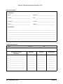
Performance Test Record
Table 2-2, "Performance Test Record," is a form you may copy and use to
record performance verification test results for the multiplexers. Table 2-2
shows multiplexer test limits, DMM measurement uncertainty, and test
accuracy ratio (TAR) values.
Test Limits
Measurement
Uncertainty
Closed Channel
Resistance Test
Test limits are defined for relay closed channel resistance and DC isolation
using the specifications in the individual module’s User’s Manual. The relay
contact resistance and DC isolation specifications are single-ended, meaning
that there is an upper limit OR a lower limit, but not both. In Table 2-2, the
Minimum or Maximum column is blank for a single-sided test.
For the performance verification tests in this manual, measurement
uncertainties are calculated based on the 3458A Digital Multimeter.
The measurement uncertainty shown in Table 2-2 is the accuracy of the
3458A using 90-day specifications. The calculations follow.
Conditions:
• 4-wire ohms function, 10 Ω range
• 90-day specifications
• Worst-case reading = 2.0 Ω
M.U. = (15 ppm of Reading + 5 ppm of Range)
= (15×10−6 ⋅ 2.0 + 5×10−6 ⋅ 10) (Ω)
_
= _________
8.0×10⁻⁵ Ω
DC Isolation Test
Conditions:
• 2-wire ohms function, 1 GΩ range
• 90-day specifications
• Worst-case reading = 1.2 GΩ (highest resistance that can
be measured with the 3458A)
M.U. = (0.5% of Reading + 10ppm of Range)
= (0.005 ⋅ 1.2×109 + 10×10−6 ⋅ 1×109) (Ω)
6
________
Ω
_
= 6.0×10
Test Accuracy Ratio
(TAR)
Chapter 2
Test Accuracy Ratios (TAR) are not defined for single-sided measurements,
so all closed-channel resistance and DC isolation measurements show NA
(Not Applicable) in the TAR column.
Verification Tests 37
Table 2-2. Performance Test Record (Page 1 of 3)
General Information
Test Facility:
Name_______________________________________
Report No._________________________________
Address_____________________________________
Date______________________________________
City/State____________________________________
Customer__________________________________
Phone______________________________________
Tested by__________________________________
Special Notes:
____________________________________________________________________________________________
____________________________________________________________________________________________
____________________________________________________________________________________________
____________________________________________________________________________________________
____________________________________________________________________________________________
____________________________________________________________________________________________
Test Equipment Record
Model ________________________________ Report No. ___________________ Date __________________
Test Equipment Used:
Description
Model No.
Trace No.
Cal Due Date
1._______________________________
_____________
_____________
_____________
2. ______________________________
_____________
_____________
_____________
3. ______________________________
_____________
_____________
_____________
4. ______________________________
_____________
_____________
_____________
5. ______________________________
_____________
_____________
_____________
6. ______________________________
_____________
_____________
_____________
7. ______________________________
_____________
_____________
_____________
38 Verification Tests
Chapter 2
Table 2-2. Performance Test Record (Page 2 of 3)
Test No/Description
Minimum*
Value
Measured Value
(V)
Maximum Measurement
Value
Uncert
Test Acc
Ratio (TAR)
2-1. Closed Channel Resistance (Values in Ohms)
HI Path Resistance
Channel 00
Channel 01
Channel 02
Channel 03
Channel 04
Channel 05
__________________
__________________
__________________
__________________
__________________
__________________
2.0
2.0
2.0
2.0
2.0
2.0
8.00E-5
8.00E-5
8.00E-5
8.00E-5
8.00E-5
8.00E-5
NA
NA
NA
NA
NA
NA
Channel 06
Channel 07
Channel 08
Channel 09
Channel 10
Channel 11
Channel 12
__________________
__________________
__________________
__________________
__________________
__________________
__________________
2.0
2.0
2.0
2.0
2.0
2.0
2.0
8.00E-5
8.00E-5
8.00E-5
8.00E-5
8.00E-5
8.00E-5
8.00E-5
NA
NA
NA
NA
NA
NA
NA
Channel 13
Channel 14
Channel 15
Channel 90
Channel 91
Channel 92
__________________
__________________
__________________
__________________
__________________
__________________
2.0
2.0
2.0
2.0
2.0
2.0
8.00E-5
8.00E-5
8.00E-5
8.00E-5
8.00E-5
8.00E-5
NA
NA
NA
NA
NA
NA
LO Path Resistance
*Single-sided specification - Minimum value does not apply
Chapter 2
Verification Tests 39
Table 2-2. Performance Test Record (Page 3 of 3)
Test
No/Description
Minimum*
Value
Measured Value (V)
Maximum*
* Value
Meas
Uncert
Test Acc
Ratio
(TAR)
2-1. Closed Channel Resistance (Values in Ohms) (cont’d)
GU Path Resistance
Channel 00
Channel 01
Channel 02
Channel 03
Channel 04
Channel 05
___________________
___________________
___________________
___________________
___________________
___________________
2.0
2.0
2.0
2.0
2.0
2.0
8.00E-5
8.00E-5
8.00E-5
8.00E-5
8.00E-5
8.00E-5
NA
NA
NA
NA
NA
NA
Channel 06
Channel 07
Channel 08
Channel 09
Channel 10
Channel 11
Channel 12
___________________
___________________
___________________
___________________
___________________
___________________
___________________
2.0
2.0
2.0
2.0
2.0
2.0
2.0
8.00E-5
8.00E-5
8.00E-5
8.00E-5
8.00E-5
8.00E-5
8.00E-5
NA
NA
NA
NA
NA
NA
NA
Channel 13
Channel 14
Channel 15
Channel 90
Channel 91
Channel 92
___________________
___________________
___________________
___________________
___________________
___________________
2.0
2.0
2.0
2.0
2.0
2.0
8.00E-5
8.00E-5
8.00E-5
8.00E-5
8.00E-5
8.00E-5
NA
NA
NA
NA
NA
NA
6.0E6
6.0E6
6.0E6
NA
NA
NA
2-2. DC Isolation (Values in Ohms)
HI to CHASSIS
HI to LO
HI to GU
1E9
1E9
1E9
__________________
__________________
__________________
*Single-sided specification - Minimum value does not apply
**Single-sided specification - Maximum value does not apply
40 Verification Tests
Chapter 2
Chapter 3
Replaceable Parts
Introduction
This chapter contains information on ordering replaceable parts for the
E1343A/44A/45A/47A/55A/56A Relay Multiplexers with specific
serial number ranges. The tables provide the following information:
• Table 3-1 lists assembly and terminal module part numbers for the relay
multiplexers.
• Table 3-2 lists replaceable parts for the following multiplexers:
E1345A with serial number
E1347A with serial number
E1355A with serial number
E1356A with serial number
2934A07622
2934A03663
3035A00331
3035A00457
or higher
or higher
or higher
or higher.
• Table 3-3 lists replaceable parts for the following high-voltage
multiplexers:
E1343A with serial number 3131A00852 or higher
E1344A with serial number 3131A00512 or higher.
• Table 3-4 shows reference designators for parts in Tables 3-2 and 3-3.
To order a part listed in Tables 3-2 and 3-3, specify the Agilent
part number and the quantity required. Send the order to your nearest Agilent
Technologies Sales and Service Office.
NOTE
If your multiplexer has a serial number lower than what is listed above, see
Appendix B, "Backdating Information," for replaceable parts ordering information.
Replaceable Parts List
See the Parts Locator diagram (Figure 3-1) for locations of replaceable parts.
See Table 3-1 for replacement part numbers for the Component Assemblies
and Terminal Modules. A relay multiplexer consists of a Component
Assembly and a Terminal Module.
A Terminal Module consists of a Terminal Card and a Terminal Case
Assembly. For example, to order an E1345A Terminal Module, use
E1345-80001. To order only the Terminal Card, use E1345-66510.
To order only the Terminal Case Assembly, use E1300-84401.
Chapter 3
Replaceable Parts 41
Table 3-1. Relay Multiplexer Assembly/Terminal Module Part Numbers
Multiplexer
Component
Assembly
Terminal
Module
Terminal
Card
Terminal
Case
Assy
E1343A 16-Channel High-Voltage Relay Mux
E1344A 16-Channel High-Voltage Relay
Mux with TC
E1345A 16-Channel Mux
E1347A 16-Channel Mux w/TC
E1355A 120-Ohm Strain Relay Mux
E1356A 350-Ohm Strain Relay Mux
E1343-66201
E1343-66201
E1343-80001
E1344-80001
E1345-66510
E1347-66510
E1300-84401
E1300-84401
E1345-66201
E1345-66201
E1345-66201
E1345-66201
E1345-80001
E1347-80001
E1355-80001
E1356-80001
E1345-66510
E1347-66510
E1355-66510
E1356-66510
E1300-84401
E1300-84401
E1300-84401
E1300-84401
Table 3-2. E1345A/47A/55A/56A Replaceable Parts
(see applicable serial number ranges on first page of this chapter)
Reference
Designator
Part
Number
Qty
Part Description
ASSEMBLIES/TERMINAL MODULES/CABLES
E1345-66201
E1345-80001
E1347-80001
E1355-80001
E1356-80001
1
1
1
1
1
ASSEMBLIES/TERMINAL MODULES
COMPONENT ASSEMBLY
E1345A TERMINAL MODULE
E1347A TERMINAL MODULE
E1355A TERMINAL MODULE
E1356A TERMINAL MODULE
E1326-61601
E1326-61604
E1326-61611
E1300-61605
E1400-61605
1
1
1
1
1
CABLES
RIBBON CABLE 6-PIN 3-IN E1326B TO RLY MUXS
RBN CBL 6-PIN 21-IN E1326A (INT) TO RLY MUXS
RBN CBL 6-PIN 20-IN E1326B (INT) TO RLY MUXS
RBN CABLE 6-PIN 2-IN RLY MUXS TO RLY MUXS
RBN CABLE 6-PIN 2.5-IN RLY MUXS TO RLY MUXS
COMPONENT ASSY (E1345-66201)
(Common to E1345/47/55/56 Relay Muxs)
See Figure 3-1
BRK1-BRK2
LBL1
LBL2
F1-F2
0050-2183
E1300-84308
E1300-84312
2110-0936
2
1
1
2
CASTING-ZN P.C. BOARD HOLDER
LBL LOGO B SIZE
ID PLATE VXI (P & P)
FUSE-SUBMINIATURE 4A 125V SMT
J1
J2
K100-K115
K90-K93
1252-1596
1252-3712
0490-1707
2
1
20
CONN-POST TYPE 2.54-PIN-SPCG 96-CONTACT
CONN-POST TYPE .100-PIN-SPCG 12-CONTACT
RELAY-REED 3A 500MA 110VAC 5VDC-COIL 5VA
MP1-MP2
P1
PNL1
1400-1546
1252-1596
E1345-00202
2
1
BRACKET PC BOARD HOLDER; BLACK; EXTR
CONN-POST TYPE 2.54-PIN-SPCG 96-CONTACT
PNL-RR RLY MUXR
SCR1-SCR2
SCR3-SCR4
SHD1
SW1
SW2
0515-0444
0515-1968
E1300-80601
3101-3142
3101-3148
2
2
1
1
1
SCREW-MACH PHD M2.5 X 0.45 8MM-LG HD
SCREW PHM 2.5 X 11 PAN - HD
SHIELD SAFETY - PLASTIC
SWITCH-DIP 8-1A SMTV 0.25A 24 VDC
SWITCH-DIP 4-1A SMT 0.05A 6 VDC
42 Replaceable Parts
Chapter 3
Table 3-2. E1345A/47A/55A/56A Replaceable Parts (cont’d)
Reference
Designator
Part
Number
Qty
Part Description
TERMINAL MODULES
A1
CS
A1
CS
E1345-80001
1
E1345A TERMINAL MODULE (See Figure 3-2)
E1345-66510
E1300-84401
1
1
TERMINAL CARD - 16 CH RLY MUX
CASE - TERMINAL MODULE ASSY
E1347-80001
1
E1347A TERMINAL MODULE (See Figure 3-2)
E1347-66510
E1300-84401
1
1
TERMINAL CARD - 16 CH T/C MUX
CASE - TERMINAL MODULE ASSY
E1355-80001
A1
CS
A1
CS
Chapter 3
E1355A TERMINAL MODULE (See Figure 3-3)
E1355-66510
E1300-84401
1
1
TERMINAL CARD - 120 OHM STRAIN RLY MUX
CASE - TERMINAL MODULE ASSEMBLY
E1356-80001
1
E1356A TERMINAL MODULE (See Figure 3-3)
E1356-66510
E1300-84401
1
1
TERMINAL CARD - 350 OHM STRAIN RLY MUX
CASE - TERMINAL MODULE ASSY
Replaceable Parts 43
Table 3-3. E1343A/44A Replaceable Parts
(see applicable serial number ranges on first page of this chapter)
Reference
Designator
Part
Number
Qty
Part Description
ASSEMBLIES/TERMINAL MODULES/CABLES
E1343-66201
E1343-80001
E1344-80001
1
1
1
ASSEMBLIES/TERMINAL MODULES
COMPONENT ASSEMBLY
E1343A TERMINAL MODULE
E1344A TERMINAL MODULE
E1326-61601
E1326-61604
E1326-61611
E1300-61605
E1400-61605
1
1
1
1
1
CABLES
RIBBON CABLE 6-PIN 3-IN E1326B TO RLY MUXS
RBN CBL 6-PIN 21-IN E1326A (INT) TO RLY MUXS
RBN CBL 6-PIN 20-IN E1326B (INT) TO RLY MUXS
RBN CABLE 6-PIN 2-IN RLY MUXS TO RLY MUXS
RBN CABLE 6-PIN 2.5-IN RLY MUXS TO RLY MUXS
COMPONENT ASSY (E1343-66201)
(common to both E1343A/44A Relay Muxs)
See Figure 3-1
BRK1-BRK2
LBL1
LBL2
F1 - F2
0050-2183
E1300-84308
E1300-84312
2110-0936
2
1
1
2
CASTING-ZN P.C. BOARD HOLDER
LBL LOGO B SIZE
ID PLATE VXI (P & P)
FUSE-SUBMINIATURE 4A 125V SMT
J1
J2
K100-K115
K90-K93
1252-1596
1252-3712
0490-1584
2
1
20
CONN-POST TYPE 2.54-PIN-SPCG 96-CONTACT
CONN-POST TYPE .100-PIN-SPCG 12-CONTACT
RELAY-REED 3A 2A 350VAC 5VDC-COIL 5VA
MP1-MP2
P1
PNL1
1400-1546
1252-1596
E1343-00202
2
1
BRACKET PC BOARD HOLDER; BLACK; EXTR
CONN-POST TYPE 2.54-PIN-SPCG 96-CONTACT
PNL-RR MUXR 16CH
SCR1-SCR2
SCR3-SCR4
SHD1
SW1
SW2
0515-0444
0515-1968
E1300-80601
3101-3142
3101-3148
2
2
1
1
1
SCREW-MACH PHD M2.5 X 0.45 8MM-LG - HD
SCREW PHM 2.5 X 11 PAN - HD
SHIELD SAFETY - PLASTIC
SWITCH-DIP 8-1A SMTV 0.25A 24 VDC
SWITCH-DIP 4-1A SMT 0.05A 6 VDC
TERMINAL MODULES
A1
CS
A1
CS
E1343-80001
1
E1343A TERMINAL MODULE (See Figure 3-2)
E1345-66510
E1300-84401
1
1
TERMINAL CARD - 16 CH RLY MUX
CASE - TERMINAL MODULE ASSY
E1344-80001
1
E1344A TERMINAL MODULE (See Figure 3-2)
E1347-66510
E1300-84401
1
1
TERMINAL CARD - 16 CH T/C MUX
CASE - TERMINAL MODULE ASSY
44 Replaceable Parts
Chapter 3
Table 3-4. Reference Designators
Reference Designators
Chapter 3
A
assembly
PCB
printed circuit board
BRK
bracket
PNL
panel
C
capacitor
Q
transistor
CR
diode
R
resistor
CS
case
RP
resistor pack
F
fuse
RT
thermistor probe
J
electrical connector (jack)
SCR
screw
JM
jumper
SHD
shield
K
relay
SW
switch
LBL
label
TB
terminal module (block)
MP
mechanical part
U
integrated circuit
P
electrical connector (plug)
Replaceable Parts 45
Parts Locators
Figures 3-1 through 3-3 show locations of replaceable parts for the E1343A,
E1344A, E1345A, E1347A, E1355A, and E1356A Relay Multiplexers with
serial numbers that fall within a specific range. (See applicable serial
number ranges on the first page of this chapter.) See Table 3-4 for
Reference Designators. Schematic diagrams are provided at the back of this
manual.
Figure 3-1. Component Assembly Parts
46 Replaceable Parts
Chapter 3
Figure 3-2. E1343A, E1344A, E1345A, E1347A Terminal Module
Mechanical Parts
Chapter 3
Replaceable Parts 47
Figure 3-3. E1355A/E1356A Terminal Module
Mechanical Parts
48 Replaceable Parts
Chapter 3
Chapter 4
Service
Introduction
This chapter contains generic service information for the multiplexers.
Also included are troubleshooting, repair, and maintenance guidelines.
Refer to the tables at the end of this chapter for information on the Parts
Locator, Component Locator and Schematic Diagram drawings included
with this manual.
WARNING
Do not perform any of the service procedures shown unless
you are a qualified, service-trained technician and have read the
WARNINGS and CAUTIONS in Chapter 1.
Equipment
Required
Equipment required for multiplexer troubleshooting and repair is listed in
Table 1-1, "Recommended Test Equipment." Any equipment that satisfies
the requirements given in the table may be substituted. To avoid damage to
the screw head slots, use a T8 Torx driver to remove the front panel handles.
Service Aids
See Chapter 3, "Replaceable Parts," or Appendix B, "Backdating
Information," for descriptions and locations of the replaceable parts,
depending on the serial number of your multiplexer. Service notes, manual
updates, and service literature for the multiplexers may be available through
Agilent Technologies. For information, contact your nearest Agilent
Technologies Sales and Service Office.
Chapter 4
Service 49
E1343A/44A
Multiplexer
Descriptions
The E1343A 16-Channel High Voltage Relay Multiplexer and the E1344A
16-Channel High Voltage Relay Multiplexer (with thermocouple
compensation) modules consist of an E1343A component assembly (part
number E1343-66201) and a terminal module. Each multiplexer provides
switching (multiplexing) of up to 16 channels (channels 00 to 15). Each
channel has HIGH (H), LOW (L), and GUARD (G) connections. See Figure
4-1 for a block diagram of these modules.
The component assembly is the same for the E1343A and E1344A. The
only difference between the two component assemblies is their module ID
jumper settings. The E1343A uses an E1343-80001 terminal assembly and
the E1344A uses an E1344-80001 terminal assembly.
Component Assembly
Description
The E1343A Component Assembly consists of 16 channel relays and four
tree switch relays. The channel relay switches are separated into two banks,
Bank 0 (channels 00 through 07) and Bank 1 (channels 08 to 15). Each bank
has its own common H, L, and G terminals that connect to the channel
switches.
The Bank 0 channel switches also connect to the AT Tree Switch Terminals
(on the terminal module) via the AT Tree Switch (Channel 90) and three
protection resistors (R26, R27, and R28). The Bank 1 channel switches
connect to the BT Tree Switch terminals (on the terminal module) via the
BT Tree Switch (Channel 91) and three protection resistors (R29, R30, and
R31).
The AT2 Tree Switch (Channel 92) connects Bank 1 channels to the AT
Tree Switch. For the E1347A only, the RT Tree Switch (Channel 93)
connects the thermistor (on the terminal module) to the Bank 1 channel
common. This allows measurement of the thermistor to compensate for
temperature measurements made with thermocouples.
The AT Tree Switch connects to the H, L, and G connections on the Analog
Bus Connector and the BT Tree Switch connects to the I+, I-, and IG
connections on the Analog Bus Connector. The Analog Bus Connector
provides direct channel connections between multiple multiplexer modules
and connections between a multiplexer module and E1326/E1411
multimeters.
Each Bank 0 and Bank 1 Common line and AT and BT Tree Switch line has
a 100Ω resistor in series to provide relay contact protection. The Analog
Bus Connector also has six 100Ω resistor in series to provide current
protection.
Terminal Module
Description
50 Service
The terminal module provides connections from user devices to the
multiplexer. The terminal module also provides connections for
multimeters, voltmeters, counters, and other measuring devices. For the
E1344A only, a thermistor is mounted on the terminal module.
Chapter 4
Terminal module connections include H, L, and G terminals for Channels
00 - 15, Bank 0 and Bank 1 Commons, and the AT and BT Tree Switches.
In addition, each channel H line has a jumper on the terminal module that
can be removed to add filter components, attenuators, or current shunts.
E1345A/47A
Multiplexer
Descriptions
The E1345A 16-Channel Relay Multiplexer and the E1347A 16-Channel
Thermocouple Relay Multiplexer modules consist of an E1345A
component assembly ( E1345-66201) and a terminal module. Each
multiplexer provides switching (multiplexing) of up to 16 channels
(channels 00 to 15). Each channel has HIGH (H), LOW (L),
and GUARD (G) connections. See Figure 4-1 for a block diagram of these
modules.
The component assembly is the same for the E1345A and E1347A.
The only difference between the two component assemblies is their jumper
settings. The E1345A has an E1345-80001 terminal module and the
E1347A has an E1347-80001 terminal module.
Component Assembly
Description
The E1345A Component Assembly consists of 16 channel relays and four
tree switch relays. The channel relay switches are separated into two banks,
Bank 0 (channels 00 through 07) and Bank 1 (channels 08 to 15). Each bank
has its own common H, L, and G terminals that connect to the channel
switches.
The Bank 0 channel switches also connect to the AT Tree Switch Terminals
(on the terminal module) via the AT Tree Switch (Channel 90) and three
protection resistors (R26, R27, and R28). The Bank 1 channel switches
connect to the BT Tree Switch terminals (on the terminal module) via the
BT Tree Switch (Channel 91) and three protection resistors (R29, R30, and
R31).
The AT2 Tree Switch (Channel 92) connects Bank 1 channels to the AT
Tree Switch. For the E1347A only, the RT Tree Switch (Channel 93)
connects the thermistor (on the terminal module) to the Bank 1 channel
common. This allows measurement of the thermistor to compensate for
temperature measurements made with thermocouples.
The AT Tree Switch connects to the H, L, and G connections on the Analog
Bus Connector and the BT Tree Switch connects to the I+, I-, and IG
connections on the Analog Bus Connector. The Analog Bus Connector
provides direct channel connections between multiple multiplexer modules
and connections between a multiplexer module and E1326/E1411
multimeters.
Each Bank 0 and Bank 1 Common line and AT and BT Tree Switch line has
a 100Ω resistor in series to provide relay contact protection. The Analog
Bus Connector also has six 100Ω resistor in series to provide current
protection.
Chapter 4
Service 51
Figure 4-1. E1343A, E1344A, E1345A, E1347A Multiplexer
Block Diagram
52 Service
Chapter 4
Terminal Module
Description
The terminal module provides connections from user devices to the
multiplexer. The terminal module also provides connections for
multimeters, voltmeters, counters, and other measuring devices. For
the E1347A only, a thermistor is mounted on the terminal module.
Terminal module connections include H, L, and G terminals for Channels
00 - 15, Bank 0 and Bank 1 Commons, and the AT and BT Tree Switches.
In addition, each channel H line has a jumper on the terminal module that
can be removed to add filter components, attenuators, or current shunts.
E1355A/56A Strain
Gage Multiplexer
Descriptions
The E1355A and E1356A multiplexers, together with an E1326B or
E1411B multimeter, provide static and dynamic strain measurement
capabilities for an Agilent 75000 Series B or 75000
Series C VXIbus system.
The E1355A and E1356A multiplexer are B-Size, 8-Channel, 120Ω and
350Ω relay strain gage multiplexers respectively. See Figure 4-2 for a block
diagram of the E1355A 120 Ohm Relay Strain Gage Multiplexer. The
block diagram shows a 1/4 bridge arrangement.
Each strain gage multiplexer provides switching (multiplexing) of up to
eight channels. Each channel has HIGH (H), LOW (L), GUARD (G), +E,
-E1, and -E2 connections to provide 1/4, 1/2, or full bridge arrangements.
See the E1355A - E1358A Strain Gage Multiplexers User’s Manual for a
complete description of strain gage bridge arrangements.
The strain gage multiplexer module consists of a component assembly and a
terminal module. The component assembly is the same for the E1355A and
E1356A multiplexer modules. The only difference between the two
component assemblies is their jumper settings. The E1355A has an
E1355-80001 terminal module and the E1356A has an E1356-80001
terminal module.
Component Assembly
Description
Chapter 4
Relay switches and relay control logic are located on the E1345A
Component Assembly. The component assembly can be configured to
provide the strain gage excitation voltage, or this voltage can be supplied
by the user. Refer to the E1355A - E1358A Strain Gage Multiplexers
User’s Manual for information on bridge excitation voltage configurations.
Table 4-1 summarizes the functions of each relay on the component
assembly.
Service 53
Figure 4-2. E1355A/56A Multiplexers Block Diagram
54 Service
Chapter 4
Table 4-1. E1355A/E1356A Relay Functions
Relay
Function
Notes
K100
K101
K102
K103
Measure strain (channel 00)
Measure strain (channel 01)
Measure strain (channel 02)
Measure strain (channel 03)
All strain gage measurements are made via the
K90 relay connected to a multimeter
K108
K109
K110
K111
Measure strain (channel 04)
Measure strain (channel 05)
Measure strain (channel 06)
Measure strain (channel 07)
All strain gage measurements are made via the
K90 relay when connected to a multimeter
K104
K105
Measure lead wire resistance (channel 08)
Measure lead wire resistance (channel 09)
This measurement increases accuracy of strain
gage measurements by canceling effects of lead
wire resistance.
K106
K107
Measure voltage across 1KΩ bridge (channel 10)
Measure voltage across 1KΩ bridge (channel 11)
These measurements check stability and condition
of the resistor pack RP1.
K112
k113
K114
K115
Shunt verification test (channel 12)
Shunt verification test (channel 13)
Measure guard voltage (Vg) (channel 14)
Measure bridge excitation voltage (+Vs) (chan 15)
Simulates known value of compression
Simulates known value of tension
Made with respect to the excitation voltage (-Vs)
K90
K91
K93
Strain gage measurements
I+ source
+Vs, -Vs excitation voltage
Terminal Module
Description
The terminal module contains the set of bridge resistors used in strain gage
measurements. The two 1kΩ bridge resistors contained in the resistor pack
(RP1) make up one half of the bridge arrangement. The other half of the
bridge arrangement for channel 0 consists of a user-supplied 120Ω strain
gage and the 120Ω resistor R0.
The junction (Vg) between the resistors R21 and R20 is known as a Wagner
Ground. The purpose of the Wagner Ground is to reduce stray leakage
currents when the Guard lead (G) is connected to the specimen being
measured.
Chapter 4
Service 55
Troubleshooting Techniques
To troubleshoot a relay multiplexer problem, you must first identify the
problem and then isolate the cause of the problem to a replaceable part. See
Chapter 3, "Replaceable Parts," or Appendix B, "Backdating Information,"
for descriptions and locations of replaceable parts, depending on the serial
number of your multiplexer.
NOTE
Identifying the
Problem
If the problem cannot be isolated to a user-replaceable part, we suggest you
return the multiplexer to Hewlett-Packard for repair, or order a replacement
assembly. See Chapter 1, "General Information," for procedures to return
multiplexers to Hewlett-Packard. See Chapter 3, "Replaceable Parts," for
information on ordering replaceable parts.
Table 4-2 lists some common problems for the relay multiplexers, along
with symptoms and possible solutions. If the problem cannot be identified
using these steps, perform component-level troubleshooting using the parts
locator diagram in Chapter 3 (Figure 3-1) and the schematic diagrams
located at the back of this manual.
Table 4-2. E1343A/44A/45A/47A/55A/56A Typical Problems
Problem Type
Symptom
Operator Errors
Non-zero error code in
response to SYST:ERR?
Possible Solutions
For E1343A/44A/45A/47A, see
Appendix C of the
E1343A/E1344A/E1345A/E1347A Relay
Multiplexers User’s Manual
For E1355A/56A, see Appendix E of
the E1355A - E1358A Strain Gage
Multiplexers User’s Manual
56 Service
Catastrophic
Failure
Multiplexer not
responding to
commands.
See "Making Visual Checks" in this
chapter
Performance
Out of
Specification
Multiplexer fails Closed
Channel Resistance
Test (Test 2-1)
See "Testing the Multiplexer" in this
chapter
Multiplexer fails DC
Isolation Test (Test 2-2)
Check user wiring and test fixture
connections.
Chapter 4
Making Visual
Checks
Visual checks for the multiplexer assemblies include the following.
See Table 4-3 for typical symptoms/actions.
• Check switches/jumpers
• Check for heat damage
• Check terminal module connections
NOTE
Refer to the appropriate user’s manual for information on logical address
and IRQ settings. If there are no apparent problems following the visual
checks, run the Performance Verification Tests in Chapter 2 to see if a relay
or other component is defective.
Table 4-3. E1343A/44A/45A/47A/55A/56A Visual Tests/Checks
Test/Check
Reference
Designator
Check
Action/Notes
Heat Damage
-------------
Discolored PC boards
Damaged insulation
Evidence of arcing
If there is damage, do not operate the
multiplexer until you have corrected the
problem.
Switch/Jumper
Settings
----SW1
SW2
IRQ Level setting
Logical address setting
Card ID setting
Factory set at 1
Factory set at 112
Set to 45A,47A,55A, or 56A as
appropriate for multiplexer
Component
Assembly
F1, F2
J1
P1
Fuse continuity
Dirty or bent connector pins
Dirty or bent connector pins
Check fuses with ohmmeter
Straighten/clean pins
Straighten/clean pins
Terminal
Module
P1
TB1 - TB5
J0, J1 (E1355A/56A)
Dirty or bent connector pins
Loose screw connections
Bridge connections
Straighten/clean pins
Check/tighten connections
Set for 1/4, 1/2, or full as required
Chapter 4
Service 57
Testing the
Multiplexer
You can use the tests and checks in Chapter 2, "Verification Tests," and the
information in Table 4-4 to isolate the problem to a relay, to a component,
or both. For example, if Test 2-1: Closed Channel Resistance Test failed
for channel 0, replace relay K100, etc. See Chapter 3, "Replaceable Parts,"
or Appendix B, "Backdating Information," for replaceable parts lists and
locator diagrams, depending on the serial number of your multiplexer.
Table 4-4. Checks for Relay/Component Failures*
If Test 2-1 failed
for this Channel:
Channel 00
Channel 01
Channel 02
Channel 03
Channel 04
Channel 05
Channel 06
Channel 07
Channel 08
Channel 09
Channel 10
Channel 11
Channel 12
Channel 13
Channel 14
Channel 15
Channels 00 - 07
Channels 08 - 15
Channel 90
Channel 91
Channel 92
Channels 90 - 92
Channels 00 - 15 and
90 - 92
If these items
failed:
Channel 93
Device Type ID
CRESET failed
Check/Replace these
Relays/ICs:
K100
K101
K102
K103
K104
K105
K106
K107
K108
K109
K110
K111
K112
K113
K114
K115
U1, U21, U38
U2, U21, U30
K90
K91
K92
U3, U21, U25
CR2, Q1, U3, U6, U8,
U12, U15, U20, U21,
U22
Replace:
K93
U10
U9, U21
* See Test 2-1: Closed Channel Resistance Test for information.
58 Service
Chapter 4
Repair and Maintenance Guidelines
This section provides guidelines for handling the relay multiplexers
including:
• ESD precautions
• Soldering printed circuit boards
• Post-repair safety checks
ESD Precautions
Electrostatic discharge (ESD) may damage static sensitive devices in the
multiplexers. This damage can range from slight parameter degradation to
catastrophic failure. When handling multiplexer assemblies, observe the
following guidelines to avoid damaging multiplexer components:
• Always use a static-free work station with a pad of conductive rubber
or similar material when handling multiplexer components.
• If a device requires soldering, be sure the assembly is placed on a
pad of conductive material. Also, be sure that you, the pad, and the
soldering iron tip are grounded to the assembly.
Soldering Printed
Circuit Boards
Some of the components on the etched circuit boards of the multiplexer
modules have plated through-holes that provide a solder path to both sides
of the insulating material. Soldering can be done from either side of the
board with equally good results. When soldering to any circuit board, keep
in mind the following guidelines:
• Avoid unnecessary component unsoldering and soldering. Excessive
replacement can result in damage to the circuit board, adjacent
components, or both.
• Do not use a high power soldering iron on etched circuit boards, as
excessive heat may lift a conductor or damage the board.
• Use a suction device or wooden toothpick to remove solder from
component mounting holes. When using a suction device, be sure
that the equipment is properly grounded.
Post-Repair Safety
Checks
Chapter 4
After making repairs to the multiplexer, inspect the multiplexer for any
signs of abnormal internally generated heat, such as discolored printed
circuit boards or components, damaged insulation, or evidence of arcing.
Determine and correct the cause of the condition. Then perform the
functional tests as described in Chapter 2, "Verification Tests," to verify that
the multiplexer is functional.
Service 59
Component Locators and Schematic Diagrams
The following tables list Component Locator Diagrams and Schematic
Diagrams provided with this manual. Refer to Table 4-5 or Table 4-6,
depending on the serial number of your E1343/44/45/47/55/56A
multiplexer. Table 4-7 lists the terminal module diagrams. The terminal
module diagram table applies to all E1343A/44A/45A/47A/56A/57A
multiplexers, regardless of their serial number.
Table 4-5. Relay Multiplexers Component Locator and Schematic Diagram Drawings
for relay multiplexers with the following serial number ranges:
E1343A with serial number
E1344A with serial number
E1345A with serial number
E1347A with serial number
E1355A with serial number
E1356A with serial number
Part Number
Parts Locator
E1345-66511
Schematic
Diagrams
E1345-66511
E1345-66511
E1345-66511
E1345-66511
E1345-66511
3131A00852
3131A00512
2934A07622
2934A03663
3035A00331
3035A00457
and higher
and higher
and higher
and higher
and higher
and higher
Drawing Number
Drawing Title
See Figure 3-1 (Chapter 3)
S-E1345-66511 (pg 1)
S-E1345-66511 (pg 2)
S-E1345-66511 (pg 3)
S-E1345-66511 (pg 4)
S-E1345-66511 (pg 5)
E1343A/E1344A/E1345A/E1347A/E1355A/E1356A - VXI Interface #1
E1343A/E1344A/E1345A/E1347A/E1355A/E1356A - VXI Interface #2
E1343A/E1344A/E1345A/E1347A/E1355A/E1356A - Relay Drivers
E1343A/E1344A/E1345A/E1347A/E1355A/E1356A - Relays
E1343A/E1344A/E1345A/E1347A/E1355A/E1356A - Part Location
Table 4-6. Relay Multiplexers Component Locator and Schematic Diagram Drawings
for relay multiplexers with the following serial number ranges:
E1343A with serial number 2934A00001 through 3131A00851
E1344A with serial number 2934A00001 through 3131A00511
E1345A with serial number 2934A00001 through 2934A07621
E1347A with serial number 2934A00001 through 2934A03662
E1355A with serial number 2934A00001 through 3035A00330
E1356A with serial number 2934A00001 through 3035A00456
Part Number
Drawing Number
Drawing Title
Component
Locator
E1345-66501
L-E1345-66501
Relay Multiplexers Component Assembly (all modules)
Schematic
Diagrams
E1345-66501
E1345-66501
E1345-66501
E1343-66501
E1345-66501
S-E1345-66501 (pg 1)
S-E1345-66501 (pg 2)
S-E1345-66501 (pg 3)
S-E1343-66501 (pg 4)
S-E1345-66501 (pg 5)
Relay Multiplexers Component Assembly - VXI Interface #1
Relay Multiplexers Component Assembly - VXI Interface #2
Relay Multiplexers Component Assembly - Relay Drivers
Relay Multiplexers Component Assembly - Relays (E1343A/44A)
Relay Multiplexers Component Assembly - Relays
( E1345A/47A/55A/56A)
60 Service
Chapter 4
Table 4-7. Terminal Module Component Locator and Schematic Diagram Drawings
(for all E1343A/44A/45A/47A/55A/56A Relay Multiplexers, regardless of serial number)
Part Number
Component
Locators
Schematic
Diagrams
Chapter 4
Drawing Number
E1345-66510
E1347-66510
L-E1345-66510
L-E1347-66510
E1355-66510
E1356-66510
L-E1355-66510
L-E1356-66510
E1345-66510
E1347-66510
S-E1345-66510
S-E1347-66510
E1355-66510
E1356-66510
S-E1355-66510
S-E1356-66510
Drawing Title
E1343A/E1345A 16-Ch. Relay Multiplexer Terminal Card
E1344A/E1347A 16-Ch. Thermocouple Relay Multiplexer
Terminal Card
E1355A 8-Ch. 120 Ohm Strain Relay Multiplexer Terminal Card
E1356A 8-Ch. 350 Ohm Strain Relay Multiplexer Terminal Card
E1343A/E1345A 16-Ch. Relay Multiplexer Terminal Card
E1344A/E1347A 16-Ch. Thermocouple Relay Multiplexer
Terminal Card
E1355A 8-Ch. 120 Ohm Strain Relay Multiplexer Terminal Card
E1356A 8-Ch. 350 Ohm Strain Relay Multiplexer Terminal Card
Service 61
Notes
62 Service
Chapter 4
Appendix A
Verification Tests - C Programs
Functional Verification Test
These programs are designed to do the Functional Verification Tests found
in Chapter 2, "Verification Tests."
Example: Self-Test
The Functional Verification Test for the multiplexer modules consists of
sending the *IDN? command and checking the response. This test can be
used to verify that the multiplexer is connected properly and is responding
to a basic command.
#include <stdio.h>
#include <sicl.h>
#define ADDR "hpib7,9,14"
void main (void)
{
INST id;
char a[256] = {0};
int i;
/* Address of device */
/* Define id as an instrument */
/* Result variable */
ionerror (I_ERROR_EXIT);
id = iopen (ADDR);
/* Open instrument session */
iprintf(id, "*IDN?\n");
iscanf (id, "%t", a);
/* Send *IDN? command */
/* Get response */
printf("\n %s", a);
getchar();
/* Print result */
/* Pause */
iclose (id);
/* Close instrument session */
}
Appendix A
Example C Programs 63
Performance
Verification
Tests
These programs are designed to do the Performance Verification Tests
found in Chapter 2, "Verification Tests."
Example: Closed
Channel
Resistance Test
The following program performs a Closed Channel Resistance Test on
Channels 00 - 15 and 90 - 92 HI, LO, and GU. If the conntact resistance for
a channel is > 2.0 Ω, the program displays the message Resistance
for Channel chan Relay is > 2.0 Ohms .
/* Closed-channel Resistance Test
E1346A */
#include <stdio.h>
#include <sicl.h>
#define ADDR "hpib7,9,14"
#define DMM "hpib7,22"
/* Address of device */
/* Address of multimeter */
void main (void)
{
/* Define id and dm as instruments */
INST id, dm;
int channel, i, j;
double ohm, R[6], result[48], value[48], result1[3][3], value1[3][3];
char cr[256] = {0};
#if defined(__BORLANDC__) && !defined(__WIN32__)
_InitEasyWin();
#endif
ionerror(I_ERROR_EXIT);
/* Open instrument session */
dm = iopen (DMM);
itimeout (dm, 10000);
iprintf (dm, "PRESET NORM\n");
iprintf (dm, "END ALWAYS\n");
iprintf (dm, "TRIG HOLD\n");
iprintf (dm, "FUNC OHMF\n");
/* ..........................Measure Protection Resistors...............................*/
printf ("\n\nMeasure Protection Resistors R38 - R43");
printf ("\n\n 1. Turn mainframe power OFF.");
printf ("\n 2. Remove E1346A component assembly from mainframe.");
printf ("\n\nPress ENTER when ready to measure protection resistors.");
getchar ();
printf ("\n\n");
for (i = 0;i <= 5; i++)
{
printf ("\nConnect DMM leads (4-wire) to resistor R%u", i+38);
printf ("\nPress ENTER when ready to measure resistance");
getchar ();
64 Example C Programs
Appendix A
iprintf (dm, "TRIG SGL\n");
iscanf (dm, "%lf", &R[i]);
iscanf (dm, "%t", cr);
printf ("\nResistance of R%u = %lf", i+38, R[i]);
}
printf ("\n\n\nInstall Component Assembly and Test Fixture");
printf ("\n\n 1. Turn Mainframe AND 3458a DMM power OFF.");
printf ("\n 2. Connect HP-IB Cable between mainframe and DMM.");
printf ("\n 3. Install E1364A Component Assembly into Mainframe.");
printf ("\n 4. Attach Test Fixture to Component Assembly.");
printf ("\n 5. Turn Mainframe and DMM power ON");
printf ("\n 6. Press ENTER when ready to begin testing.");
getchar ();
/*...............Measure Channels 00-47 and 90-92 (HI, Lo, and G)...........*/
id = iopen(ADDR);
iprintf (id, "*RST\n");
iprintf (dm, "PRESET NORM;TRIG HOLD\n");
iprintf (dm, "END ALWAYS\n");
iprintf (dm, "FUNC OHMF\n");
j = 100;
printf ("\n\nChannel 00-47 and 90-92 HI measurements");
printf ("\n\n 1. Connect DMM Sense and Input HI leads to COMMON HI.");
printf ("\n 2. Connect DMM Sense and Input LO leads to VOLTAGE SENSE HI.");
printf ("\n 3. Press ENTER when connections are complete.");
getchar ();
for (i = 0;i <= 47; i++)
{
iprintf (id, "CLOS (@%u)\n", j+i);
iprintf (dm, "TRIG SGL\n");
iscanf (dm, "%lf", &value[i]);
iscanf (dm, "%t", cr);
iprintf (id, "OPEN (@%u)\n", j+i);
result[i] = value[i] - R[5];
if (result[i] < 0) result[i] = 0;
if (result[i] > 2.0) printf ("\n*** Resistance for Channel %u HI path is 2.0 Ohms
*** %lf", i, result[i]);
}
printf ("\n\nMeasurements complete for Channels 00-47 and 90-92 HI");
printf ("\nPress ENTER for Channels 90-92 LO measurements");
getchar ();
/*...........................Measure Channels 90-92 LO..................................*/
iprintf (id, "*RST\n");
printf ("\n\n\nChannels 90-92 LO measurements");
printf ("\n\n 1. Connect DMM Sense and Input HI leads to COMMON LO.");
printf ("\n 2. Connect DMM Sense and Input LO leads to VOLTAGE SENSE
LO.");
printf ("\n 3. Press ENTER when connections are complete.");
getchar ();
Appendix A
Example C Programs 65
j = 100;
for (i = 0;i <= 2; i++)
{
iprintf (id, "CLOS (@%u)\n", j);
iprintf (dm, "TRIG SGL\n");
iscanf (dm, "%lf", &value1[i][1]);
iscanf (dm, "%t", cr);
iprintf (id, "OPEN (@%u)\n", i*8);
result1[i][1] = value1[i][1] - R[42];
if (result1[i][1] < 0) result1[i][1] = 0;
if (result1[i][1] > 2.0) printf ("\n*** Resistance for Channel %u LO Relay is 2.0
Ohms", i+90);
j = j + 8;
}
printf ("\n\nMeasurements complete for Channels 90-92 LO.");
printf ("\nPress ENTER for Channel 90-92 G measurements.");
getchar ();
/*...........................Measure Channels 90-92 G...................................*/
printf ("\n\n\nChannels 90-92 G measurements");
printf ("\n\n 1. Connect DMM Sense and Input HI leads to COMMON G.");
printf ("\n 2. Connect DMM Sense and Input LO leads to VOLTAGE SENSE G.");
printf ("\n 3. Press ENTER when connections are complete.");
getchar ();
j = 100;
for (i = 0;i <= 2; i++)
{
iprintf (id, "CLOS (@%u)\n", j);
iprintf (dm, "TRIG SGL\n");
iscanf (dm, "%lf", &value1[i][2]);
iscanf (dm, "%t", cr);
iprintf (id, "OPEN (@%u)\n", i*8);
result1[i][2] = value1[i][2] - R[42];
if (result1[i][2] < 0) result1[i][2] = 0;
if (result1[i][2] > 2.0) printf ("\n*** Resistance for Channel %u G Relay is 2.0
Ohms", i+90);
j = j + 8;
}
printf ("\n\nMeasurements complete for Channels 90-92 G.");
printf ("\nPress ENTER for Channel 93 HI, LO, and G measurements.");
getchar ();
/*...........................Measure Channel 93 HI, LO, and G...........................*/
j = 193;
printf ("\n\n\nChannel 93 HI, LO, and G measurements");
printf ("\n\n 1. Connect DMM Sense and Input HI leads to VOLTAGE SENSE
HI.");
printf ("\n 2. Connect DMM Sense and Input LO leads to CURRENT SOURCE
HI.");
printf ("\n 3. Press ENTER when connections are complete.");
66 Example C Programs
Appendix A
getchar ();
iprintf (id, "CLOS (@%u)\n", j);
iprintf (dm, "TRIG SGL\n");
iscanf (dm, "%lf", &value1[0][3]);
iscanf (dm, "%t", cr);
result1[0][3] = value1[0][3] - R[38] - R[43];
iprintf (id, "open (@%u)\n", j);
if (result1[0][3] < 0) result1[0][3] = 0;
if (result1[0][3] > 2.0) printf ("\n*** Resistance for Channel 93 HI Relay is 2.0
Ohms");
printf ("\n\n 1. Connect DMM Sense and Input HI leads to VOLTAGE SENSE
LO.");
printf ("\n 2. Connect DMM Sense and Input LO leads to CURRENT SOURCE
LO.");
printf ("\n 3. Press ENTER when connections are complete.");
getchar ();
iprintf (id, "CLOS (@%u)\n", j);
iprintf (dm, "TRIG SGL\n");
iscanf (dm, "%lf", &value1[1][3]);
iscanf (dm, "%t", cr);
result1[1][3] = value1[1][3] - R[39] - R[42];
iprintf (id, "open (@%u)\n", j);
if (result1[1][3] < 0) result1[1][3] = 0;
if (result1[1][3] > 2.0) printf ("\n*** Resistance for Channel 93 LO Relay is 2.0
Ohms");
printf ("\n\n 1. Connect DMM Sense and Input HI leads to VOLTAGE SENSE
G.");
printf ("\n 2. Connect DMM Sense and Input LO leads to CURRENT SOURCE
G.");
printf ("\n 3. Press ENTER when connections are complete.");
getchar ();
iprintf (id, "CLOS (@%u)\n", j);
iprintf (dm, "TRIG SGL\n");
iscanf (dm, "%lf", &value1[2][3]);
iscanf (dm, "%t", cr);
result1[2][3] = value1[2][3] - R[40] - R[41];
iprintf (id, "open (@%u)\n", j);
if (result1[2][3] < 0) result1[2][3] = 0;
if (result1[2][3] > 2.0) printf ("\n*** Resistance for Channel 93 G Relay is 2.0
Ohms");
printf ("\n\nMeasurements complete for Channel 93 HI, LO, and G.");
printf ("\nPress ENTER to display measurement results.");
getchar ();
/*...........................Display Measurement Results................................*/
printf ("\n\n\nChannels 00-47 & 90-92 HI Contact Resistance\n");
for (i = 0;i <= 23; i++)
{
printf ("\n CH %u & %u %6.4lf Ohms CH %u & %u %6.4lf
Ohms",i,90+(i/8),result[i],i+24,90+(i/8),result[i+24]);
}
Appendix A
Example C Programs 67
printf ("\n\nChannels 90-92 LO and G Contact Resistance\n");
printf ("\n CH 90 LO %6.4lf Ohms CH 91 LO %6.4lf Ohms CH 92 LO %6.4lf
Ohms", result1[0][1],result1[1][1],result1[2][1]);
printf ("\n CH 90 G %6.4lf Ohms CH 91 G %6.4lf Ohms CH 92 G %6.4lf
Ohms", result1[0][2],result1[1][2],result1[2][2]);
printf ("\n\nChannel 93 HI, LO, and G Contact Resistance\n");
printf ("\n CH 93 HI %6.4lf Ohms\n CH 93 LO %6.4lf Ohms\n CH 93 G
%6.4lf Ohms\n",result1[0][3],result1[1][3],result1[2][3]);
iclose (id);
iclose (dm);
/* Close instrument session */
}
Example: DC
Isolation Test
This example performs DC Isolation Tests for HI to Chassis, HI to LO, and
HI to GU (Guard).
/* DC Isolation Test
E1346A */
#include <stdio.h>
#include <sicl.h>
#define ADDR "hpib7,9,14"
#define DMM "hpib7,22"
void main (void)
{
INST id, dm;
/* Address of device */
/* Address of multimeter */
/* Define id and dm as instruments
*/
char reading[256]= {0};
char cr[256]= {0};
/* Result variable */
#if defined(__BORLANDC__) && !defined(__WIN32__)
_InitEasyWin();
#endif
ionerror(I_ERROR_EXIT);
id = iopen (ADDR);
dm = iopen (DMM);
/* Open instrument session */
iprintf (dm, "PRESET NORM;TRIG HOLD\n");
iprintf (dm, "FUNC OHM;RANGE 1E9\n");
iprintf (dm, "END ALWAYS\n");
iprintf (id, "*RST\n");
iprintf (id, "CLOS (@193,100,108,116)\n");
/*........................HI to CHASSIS................................*/
printf ("\n\nConnect DMM HI and LO to E1346A COMMON HI and CHASSIS");
getchar ();
68 Example C Programs
Appendix A
iprintf (dm, "TRIG SGL\n");
iscanf (dm, "%t", reading);
printf ("\nDC Isolation -- HI to CHASSIS ");
printf (" R = %s Ohms", reading);
/*........................HI to LO.....................................*/
printf ("\n\nConnect DMM HI and LO to E1346A COMMON HI and COMMON
LO");
getchar ();
iprintf (dm, "TRIG SGL\n");
iscanf (dm, "%t", reading);
printf ("\nDC Isolation -- HI to LO ");
printf (" R = %s Ohms", reading);
/*........................HI to GUARD..................................*/
printf ("\n\nConnect DMM HI and LO to E1346A COMMON HI and COMMON G");
getchar ();
iprintf (dm, "TRIG SGL\n");
iscanf (dm, "%t", reading);
printf ("\nDC Isolation -- HI to GUARD ");
printf (" R = %s Ohms", reading);
/*.....................................................................*/
iprintf (id, "OPEN (@193,100,108,116)\n");
iclose (id);
iclose (dm);
/* Close instrument session */
}
Appendix A
Example C Programs 69
Notes
70 Example C Programs
Appendix A
Appendix B
Backdating Information
Introduction
This chapter contains information for ordering replaceable parts for the
E1343A/44A/45A/47A/55A/56A Relay Multiplexers with specific serial
number ranges not covered in Chapter 3. The tables provide the following:
• Table B-1 lists assembly and terminal module part numbers for the
relay multiplexers.
• Table B-2 lists replaceable parts for the following relay multiplexers:
E1345A w/serial number 2934A00001 through 2934A07621
E1347A w/serial number 2934A00001 through 2934A03662
E1355A w/serial number 2934A00001 through 3035A00330
E1356A w/serial number 2934A00001 through 3035A00456
• Table B-3 lists replaceable parts for the following high-voltage
multiplexers:
E1343A w/serial number 2934A00001 through 3131A00851
E1344A w/serial number 2934A00001 through 3035A00511
• Table B-4 shows reference designators for parts in Tables B-2 and
B-3.
To order a part listed in Table B-2 or Table B-3, specify the Agilent part
number and the quantity required. Send the order to your nearest Agilent
Technologies Sales and Service Office
NOTE
If your multiplexer has a higher serial number, see Chapter 3,
"Replaceable Parts," for replaceable parts ordering information.
Replaceable Parts List
See the Parts Locator diagram (Fig. B-1) or the Component Locator (in the
back of this manual) for locations of replaceable parts. See Table B-1 for
replacement part numbers for the Component Assemblies and Terminal
Modules. A relay multiplexer consists of a Component Assembly and a
Terminal Module.
A Terminal Module consists of a Terminal Card and a Terminal Case
Assembly. For example, to order an E1345A Terminal Module, use
Appendix B
Backdating Information 71
E1345-80001. To order only the Terminal Card, use E1345-66510. To order
only the Terminal Case Assembly, use E1300-84401.
Table B-1. Relay Multiplexer Assembly/Terminal Module Part Numbers
Multiplexer
E1343A 16-Channel High Voltage Relay
Mux
E1344A 16-Channel High Voltage Relay
Mux with TC
E1345A 16-Channel Mux
E1347A 16-Channel Mux w/TC
E1355A 120 Ohm Strain Rly Mux
E1356A 350 Ohm Strain Rly Mux
Component
Assembly
Terminal
Module
Terminal Card
Terminal
Case Assy
E1343-66201
E1343-66201
E1343-80001
E1344-80001
E1345-66510
E1347-66510
E1300-84401
E1300-84401
E1345-66201
E1345-66201
E1345-66201
E1345-66201
E1345-80001
E1347-80001
E1355-80001
E1356-80001
E1345-66510
E1347-66510
E1355-66510
E1356-66510
E1300-84401
E1300-84401
E1300-84401
E1300-84401
Table B-2. E1345A/47A/55A/56A Replaceable Parts
(See applicable Serial Number ranges listed on the first page of this chapter)
Reference
Designator
Part
Number
Qty
Part Description
ASSEMBLIES/TERMINAL MODULES/CABLES
ASSEMBLIES/TERMINAL MODULES
E1345-66201
E1345-80001
E1347-80001
E1355-80001
E1356-80001
1
1
1
1
1
COMPONENT ASSEMBLY
E1345A TERMINAL MODULE
E1347A TERMINAL MODULE
E1355A TERMINAL MODULE
E1356A TERMINAL MODULE
CABLES
E1326-61601
E1326-61604
E1326-61611
E1300-61605
E1400-61605
1
1
1
1
1
RIBBON CABLE 6-PIN 3-IN E1326B TO RLY MUXS
RBN CBL 6-PIN 21-IN E1326A (INT) TO RLY MUXS
RBN CBL 6-PIN 20-IN E1326B (INT) TO RLY MUXS
RBN CABLE 6-PIN 2-IN RLY MUXS TO RLY MUXS
RBN CABLE 6-PIN 2.5-IN RLY MUXS TO RLY MUXS
COMPONENT ASSEMBLY (HP E1345-66201)
(Common to HP E1345/47/55/56 Relay Muxs)
See Figure B-1 and Component Locator in back of manual.
BRK1-BRK2
LBL1
LBL2
F1
F2
0050-2183
E1300-84308
E1300-84312
2110-0712
2110-0665
72 Backdating Information
2
1
1
1
1
CASTING-ZN P.C. BOARD HOLDER
LBL LOGO B SIZE
ID PLATE VXI (P & P)
FUSE-SUBMINIATURE 4A 125V NTD AX
FUSE-SUBMINIATURE 1A 125V NTD AX UL CSA
Appendix B
Reference
Designator
Part
Number
Qty
Part Description
COMPONENT ASSY (CONT’D...HP E1345-66201)
J1
J2
J3
K0-K15
K90-K93
1252-1596
1252-3712
1251-6001
0490-1707
2
1
1
20
CONN-POST TYPE 2.54-PIN-SPCG 96-CONTACT
CONN-POST TYPE .100-PIN-SPCG 12-CONTACT
CONN-POST TYPE .100-PIN-SPCG 6-CONTACT
RELAY-REED 3A 500MA 110VAC 5VDC-COIL 5VA
MP1-MP2
P1
P3-P4
PNL1
1400-1546
1252-1596
1258-0141
E1345-00202
2
2
1
BRACKET PC BOARD HOLDER; BLACK; EXTR
CONN-POST TYPE 2.54-PIN-SPCG 96-CONTACT
JUMPER-REMOVABLE FOR .025 IN SQ PINS
PNL-RR RLY MUXR
SCR1-SCR2
SCR3-SCR4
SHD1
SW1
0515-0444
0515-1968
E1300-80601
3101-3066
2
2
1
1
SCREW-MACH PHD M2.5 X 0.45 8MM-LG - HD
SCREW PHM 2.5 X 11 PAN - HD
SHIELD SAFETY - PLASTIC
SWITCH-DIP ROCKER 8-1A 0.15A 30 VDC
A1
PRINTED CIRCUIT ASSY, 16 CHAN MULTI
A1C1
A1C2-C3
A1C5
A1C6
A1C7-C9
A1C11
A1C17
A1C38-C42
A1C44
A1C45-C46
0180-1746
0160-4822
0160-4801
0160-4822
0160-4801
0160-3334
0160-4835
0160-4835
0180-1746
0160-4835
A1C48
A1CR1
A1CR2
A1JM15-JM16
A1Q1
A1R2
A1R3
A1R5
A1R6-R7
A1R9
0160-4835
1902-0554
1901-1065
7175-0057
1855-0518
0757-0453
0698-3615
0698-8737
0757-0465
0757-0417
A1R10
A1R20-R37
A1RP1-RP3
A1RP25-RP26
A1RP32
0757-0442
0698-8768
1810-0265
1810-0279
1810-0279
Appendix B
2
3
4
1
9
1
1
2
1
1
1
1
2
1
1
18
3
3
CAPACITOR-FXD 15uF +-0% 20 V TA
CAPACITOR-FXD 1000pF +-5% 100 V CER C0G
CAPACITOR-FXD 100pF +-5% 100 V CER C0G
CAPACITOR-FXD 1000pF +- 5% 100 V CER C0G
CAPACITOR-FXD 100pF +-5% 100 V CER C0G
CAPACITOR-FXD 0.01uF +-10% 50 V CER X7R
CAPACITOR-FXD 0.1uF +-10% 50V CER X7R
CAPACITOR-FXD 0.1uF +-10% 50V CER X7R
CAPACITOR-FXD 15uF +-10% 20 V TA
CAPACITOR-FXD 0.1uF +-10% 50V CER X7R
CAPACITOR-FXD 0.1uF +-10% 50V CER X7R
DIODE-ZENER 10V 5% PD=1W IR=10UA
DIODE-POWER RECTIFIER 1N4936 400V 1A 200NS
RESISTOR 0 MFS
TRANSISTOR MOSFET N-CHAN E-MODE SI
RESISTOR 30.1K +-1% .125W TF TC=0+-100
RESISTOR 47 +-5% 2W MO TC=0+-200
RESISTOR 100K +-5% .25W CC TC=-400/+800
RESISTOR 100K +-1% .125W TF TC=0+-100
RESISTOR 562 +-1% .125W TF TC=0+-100
RESISTOR 10K +-1% .125W TF TC=0+-100
RESISTOR 100 +-5% .25W CC TC=-400/+500
NETWORK-RESISTOR 16-DIP 680.0 OHM X 8
NETWORK-RES 10-SIP 4.7K OHM X 9
NETWORK-RES 10-SIP 4.7K OHM X 9
Backdating Information 73
Reference
Designator
Part
Number
Qty
Part Description
COMPONENT ASSY (CONT’D...HP E1345-66201)
A1U1-U3
A1U5
A1U6
A1U7-U8
A1U9
1858-0069
1820-4057
1820-6731
1820-3079
1820-3081
3
1
1
2
1
TRANSISTOR ARRAY 18-PIN PLASTIC DIP
IC BUFFER TTL/F NAND QUAD 2-INP
IC GATE-ARRAY CMOS
IC DCDR CMOS/74HC BIN 3-TO-8-LINE
IC FF CMOS/74HC D-TYPE POS-EDGE-TRIG
A1U10-U11
1820-3975
2
IC-DRIVER CMOS/74HC LINE OCTAL
A1U12
A1U15
A1U16
A1U17-U18
A1U19
1820-4590
1820-4147
1820-3714
1820-3631
1820-3664
1
1
2
2
1
IC MV CMOS/74HC MONOSTBL RETRIG DUAL
IC LCH CMOS/74HCT TRANSPARENT OCTL
IC TRANSCEIVER TTL/ALS BUS OCTL
IC COMPARATOR CMOS/74HCT MAGTD 8-BIT
IC GATE CMOS/HCT NAND QUAD 2-INP
A1U20
A1U21-U22
A1U25
A1U30
A1U35
A1U38
1820-4242
1820-4643
1820-4086
1820-4086
1820-3714
1820-4086
1
2
3
IC SCHMITT-TRIG CMOS/74HCT INV HEX
IC GATE CMOS/74HCT NOR QUAD 2-INP
IC FF CMOS/74HCT D-TYPE POS-EDGE-TRIG
IC FF CMOS/74HCT D-TYPE POS-EDGE-TRIG
IC TRANSCEIVER TTL/ALS BUS OCTL
IC FF CMOS/74HCT D-TYPE POS-EDGE-TRIG
E1345-80001
1
E1345A TERMINAL MODULE (See Figure B-2)
E1345-66510
E1300-84401
1
1
TERM CARD - 16 CH RLY MUX
CASE - TERM MODULE ASSY
E1347-80001
1
E1347A TERMINAL MODULE (See Figure B-2)
E1347-66510
E1300-84401
1
1
TERM CARD - 16 CH T/C MUX
CASE - TERM MODULE ASSY
E1355-80001
1
E1355A TERMINAL MODULE (See Figure B-3)
E1355-66510
E1300-84401
1
1
TERM CARD - 120 OHM STRAIN RLY MUX
CASE - TERM MODULE ASSY
E1356-80001
1
E1356A TERMINAL MODULE (See Figure B-3)
E1356-66510
E1300-84401
1
1
TERM CARD - 350 OHM STRAIN RLY MUX
CASE - TERM MODULE ASSY
A1
CS
A1
CS
A1
CS
A1
CS
74 Backdating Information
Appendix B
Table B-3. E1343A, E1344A Replaceable Parts
(See applicable Serial Number ranges listed on the first page of this chapter))
Reference
Designator
Part Number
Qty.
Part Description
ASSEMBLIES/TERMINAL MODULES/CABLES
ASSEMBLIES/TERMINAL MODULES
E1343-66201
E1343-80001
E1344-80001
1
1
1
COMPONENT ASSEMBLY
E1343A TERMINAL MODULE
E1344A TERMINAL MODULE
CABLES
E1326-61601
E1326-61604
E1326-61611
E1300-61605
E1400-61605
1
1
1
1
1
RIBBON CABLE 6-PIN 3-IN E1326B TO RLY MUXS
RBN CBL 6-PIN 21-IN E1326A (INT) TO RLY MUXS
RBN CBL 6-PIN 20-IN E1326B (INT) TO RLY MUXS
RBN CABLE 6-PIN 2-IN RLY MUXS TO RLY MUXS
RBN CABLE 6-PIN 2.5-IN RLY MUXS TO RLY MUXS
COMPONENT ASSY (E1343-66201)
(Common to both E1343A/44A Relay Muxs)
See Figure B-1 and Component Locator in back of manual.
BRK1-BRK2
LBL1
LBL2
F1
F2
0050-2183
E1300-84308
E1300-84312
2110-0712
2110-0665
2
1
1
1
1
CASTING-ZN P.C. BOARD HOLDER
LBL LOGO B SIZE
ID PLATE VXI (P & P)
FUSE-SUBMINIATURE 4A 125V NTD AX
FUSE-SUBMINIATURE 1A 125V NTD AX UL CSA
J1
J2
J3
K0-K15
K90-K93
1252-1596
1252-3712
1251-6001
0490-1584
2
1
1
20
CONN-POST TYPE 2.54-PIN-SPCG 96-CONTACT
CONN-POST TYPE .100-PIN-SPCG 12-CONTACT
CONN-POST TYPE .100-PIN-SPCG 6-CONTACT
RELAY-REED 3A 2A 350VAC 5VDC-COIL 5VA
MP1-MP2
P1
P3-P4
PNL1
1400-1546
1252-1596
1258-0141
E1343-00202
2
2
1
BRACKET PC BOARD HOLDER; BLACK; EXTR
CONN-POST TYPE 2.54-PIN-SPCG 96-CONTACT
JUMPER-REMOVABLE FOR .025 IN SQ PINS
PNL-RR MUXR 16CH
SCR1-SCR2
SCR3-SCR4
SHD1
SW1
0515-0444
0515-1968
E1300-80601
3101-3066
2
2
1
1
SCREW-MACH PHD M2.5 X 0.45 8MM-LG - HD
SCREW PHM 2.5 X 11 PAN - DH
SHIELD SAFETY - PLASTIC
SWITCH-DIP ROCKER 8-1A 0.15A 30 VDC
Appendix B
Backdating Information 75
Reference
Designator
Part Number
Qty.
Part Description
COMPONENT ASSY (CONT’D...E1343-66201)
PRINTED CIRCUIT ASSY, 16 CHAN MULTI
A1
A1C1
A1C2-C3
A1C5
A1C6
A1C7-C9
A1C11
A1C17
A1C38-C42
A1C44
A1C45-C46
0180-1746
0160-4822
0160-4801
0160-4822
0160-4801
0160-3334
0160-4835
0160-4835
0180-1746
0160-4835
A1C48
A1CR1
A1CR2
A1JM15-JM16
A1Q1
A1R2
A1R3
A1R5
A1R6-R7
A1R9
0160-4835
1902-0554
1901-1065
7175-0057
1855-0518
0757-0453
0698-3615
0698-8737
0757-0465
0757-0417
A1R10
A1R20-R21
A1R22
A1R23-R24
A1R25
A1R26-R27
0757-0449
0698-8768
0698-8777
0698-8768
0698-8777
0698-8768
A1R28
A1R29-R30
A1R31
A1R32-R33
A1R34
A1R35-R36
0698-8777
0698-8768
0698-8777
0698-8768
0698-8777
0698-8768
A1R37
A1RP1-RP3
A1RP25-RP26
A1RP32
A1U1-U3
A1U5
0698-8777
1810-0265
1810-0279
1810-0279
1858-0069
1820-4057
76 Backdating Information
2
3
4
1
9
1
1
2
1
1
1
1
2
1
1
12
6
CAPACITOR-FXD 15uF +-10% 20 V TA
CAPACITOR-FXD 1000pF +-5% 100 V CER C0G
CAPACITOR-FXD 100pF +-5% 100 V CER C0G
CAPACITOR-FXD 1000pF +-5% 100 V CER C0G
CAPACITOR-FXD 100pF +-5% 100 V CER C0G
CAPACITOR-FXD 0.01uF +-10% 50 V CER X7R
CAPACITOR-FXD 0.1uF +-10% 50V CER X7R
CAPACITOR-FXD 0.1uF +-10% 50V CER X7R
CAPACITOR-FXD 15uF +-10% 20 V TA
CAPACITOR-FXD 0.1uF +-10% 50V CER X7R
CAPACITOR-FXD 0.1uF +-10% 50V CER X7R
DIODE-ZENER 10V 5% PD=1W IR=10UA
DIODE-POWER RECTIFIER 1N4936 400V 1A 200NS
RESISTOR 0 MFS
TRANSISTOR MOSFET N-CHAN E-MODE SI
RESISTOR 30.1K +-1% .125W TF TC=0+-100
RESISTOR 47 +-5% 2W MO TC=0+-200
RESISTOR 100K +-5% .25W CC TC=-400/+800
RESISTOR 100K +-1% .125W TF TC=0+-100
RESISTOR 562 +-1% .125W TF TC=0+-100
RESISTOR 20K +-1% .125W TF TC=0+-100
RESISTOR 100 +-5% .25W CC TC=-400/+500
RESISTOR 1k +-5% .25W CC TC=-400/+900
RESISTOR 100 +-5% .25W CC TC=-400/+500
RESISTOR 1k +-5% .25W CC TC=-400/+900
RESISTOR 100 +-5% .25W CC TC=-400/+500
RESISTOR 1k +-5% .25W CC TC=-400/+900
RESISTOR 100 +-5% .25W CC TC=-400/+500
RESISTOR 1k +-5% .25W CC TC=-400/+900
RESISTOR 100 +-5% .25W CC TC=-400/+500
RESISTOR 1k +-5% .25W CC TC=-400/+900
RESISTOR 100 +-5% .25W CC TC=-400/+500
3
3
3
1
RESISTOR 1k +-5% .25W CC TC=-400/+900
NETWORK-RESISTOR 16-DIP 680.0 OHM X 8
NETWORK-RES 10-SIP 4.7K OHM X 9
NETWORK-RES 10-SIP 4.7K OHM X 9
TRANSISTOR ARRAY 18-PIN PLASTIC DIP
IC BUFFER TTL/F NAND QUAD 2-INP
Appendix B
Reference
Designator
Part Number
Qty.
Part Description
COMPONENT ASSY (CONT’D...E1343-66201)
A1U6
A1U7-U8
A1U9
A1U10-U11
A1U12
A1U15
1820-6731
1820-3079
1820-3081
1820-3975
1820-4590
1820-4147
1
2
1
2
1
1
IC GATE-ARRAY CMOS
IC DCDR CMOS/74HC BIN 3-TO-8-LINE
IC FF CMOS/74HC D-TYPE POS-EDGE-TRIG
IC-DRIVER CMOS/74HC LINE OCTAL
IC MV CMOS/74HC MONOSTBL RETRIG DUAL
IC LCH CMOS/74HCT TRANSPARENT OCTL
A1U16
A1U17-U18
A1U19
A1U20
A1U21-U22
A1U25
1820-3714
1820-3631
1820-3664
1820-4242
1820-4643
1820-4086
2
2
1
1
2
3
IC TRANSCEIVER TTL/ALS BUS OCTL
IC COMPARATOR CMOS/74HCT MAGTD 8-BIT
IC GATE CMOS/HCT NAND QUAD 2-INP
IC SCHMITT-TRIG CMOS/74HCT INV HEX
IC GATE CMOS/74HCT NOR QUAD 2-INP
IC FF CMOS/74HCT D-TYPE POS-EDGE-TRIG
A1U30
A1U35
A1U38
1820-4086
1820-3714
1820-4086
IC FF CMOS/74HCT D-TYPE POS-EDGE-TRIG
IC TRANSCEIVER TTL/ALS BUS OCTL
IC FF CMOS/74HCT D-TYPE POS-EDGE-TRIG
TERMINAL MODULES
A1
CS
A1
CS
E1343-80001
1
E1343A TERMINAL MODULE (See Figure B-2)
E1345-66510
E1300-84401
1
1
TERM CARD - 16 CH RLY MUX
CASE - TERM MODULE ASSY
E1344-80001
1
E1344A TERMINAL MODULE (See Figure B-2)
1
1
TERM CARD - 16 CH T/C MUX
CASE - TERM MODULE ASSY
E1347-66510
E1300-84401
Table B-4. Reference Designators
Reference Designators
A
BRK
C
CR
CS
F
J
JM
K
LBL
MP
P
Appendix B
assembly
bracket
capacitor
diode
case
fuse
electrical connector (jack)
jumper
relay
label
mechanical part
electrical connector (plug)
PCB
PNL
Q
R
RP
RT
SCR
SHD
SW
TB
U
printed circuit board
panel
transistor
resistor
resistor pack
thermistor probe
screw
shield
switch
terminal block (module)
integrated circuit
Backdating Information 77
Parts Locators
Figures B-1 through B-3 show locations of replaceable parts for the
E1343A, E1344A, E1345A, E1347A, E1355A, and E1356A Relay
Multiplexers with serial numbers that fall within a specific range. (See
applicable serial number ranges on the first page of this chapter.) See Table
B-4 for Reference Designators. A more detailed component locator and
schematic diagrams are provided at the back of this manual.
Figure B-1. Component Assembly Parts
78 Backdating Information
Appendix B
Figure B-2. E1343A/44A/45A/47A Terminal Module Mechanical Parts
Appendix B
Backdating Information 79
Figure B-3. E1355A/56A Terminal Module Mechanical Parts
80 Backdating Information
Appendix B
Copyright © Agilent Technologies, Inc. 2005
*E1345-90013*
E1345-90013