1
n
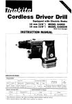
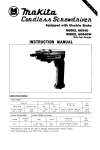
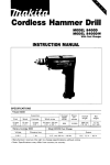
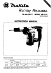
MODEL 903D
MODEL 903DW
With Fast Charger
INSTRUCTION MANUAL
"'"I
Collet size
No load speed
IRPM)
Overall length
Net weight
3 mm or 1/E''
19,000
295 mm I1 1 518'')
0 7 kg 11.5 Ibs)
Battery Cartridge 9000
Voltage
9 6 V
I
I
Model DC9100 Fast Charger
I
I
Charging time
1 Hr
~~
~~
Input
A C only 5 0 H r
~
60 Hz
~
Manufacturer reserves the right t o change specifications without notice.
Note: Specifications may differ from country to country.
I
I
output
DC 96V
IMPORTANT
SAFETY INSTRUCTIONS
(For All Tools)
WARNING: WHEN USING ELECTRIC TOOLS, BASIC SAFETY PRECAUTIONS SHOULD ALWAYS BE FOLLOWED TO
REDUCE THE RISK OF FIRE, ELECTRIC SHOCK, AND PERSONAL INJURY, INCLUDING THE FOLLOWING:
READ ALL INSTRUCTIONS.
1. KEEP WORK AREA CLEAN. Cluttered areas and benches invite injuries.
2. CONSIDER WORK AREA ENVIRONMENT. Don't use power tools in damp
or wet locations. Keep work area well lit. Don't expose power tools t o rain.
Don't use tool in presence of flammable liquids or gases.
3. KEEP CHILDREN AWAY. All visitors should be kept away from work area.
Don't let visitors contact tool or extension cord.
4. STORE IDLE TOOLS. When not in use, tools should be stored in dry, and high
or locked-up place
- out
of reach of children.
5. DON'T FORCE TOOL. It will do the job better and safer at the rate for which
it was intended.
6. USE RIGHT TOOL. Don't force small tool or attachment t o do the job of a
heavy-duty tool. Don't use tool for purpose not intended.
7. DRESS PROPERLY. Don't wear loose clothing or jewelry. They can be caught
in moving parts. Rubber gloves and non-skid footwear are recommended
when working outdoors. Wear protective hair covering t o contain long hair.
8. USE SAFETY GLASSES. Also use face or dust mask if cutting operation is
dusty.
9. DON'T ABUSE CORD. Never carry tool by cord or yank it t o disconnect from
receptacle. Keep cord from heat, oil, and sharp edges.
Use clamps or a vise t o hold work. It's safer than using
your hand and it frees both hands t o operate tool.
IO. SECURE WORK.
11. DON'T OVERREACH. Keep proper footing and balance at all times.
12. MAINTAIN TOOLS WITH CARE. Keep tools sharp and clean for better and
safer performance. Follow instructions for lubricating and changing accessories. Inspect tool cords periodically and if damaged, have repaired by authorized service facility. Inspect extension cords periodically and replace if
damaged. Keep handles dry, clean, and free from oil and grease.
13. DISCONNECT TOOLS. When not in use, before servicing, and when changing accessories, such as blades, bits, cutters.
14. REMOVE ADJUSTING KEYS AND WRENCHES. Form habit of checking t o
see that keys and adjusting wrenches are removed from tool before turning
it on.
15. AVOID UNINTENTIONAL STARTING. Don't carry plugged-in tool w i t h finger
on switch. Be sure switch is OFF when plugging in.
16. OUTDOOR USE EXTENSION CORDS. When tool is used outdoors, use only
extension cords intended for use outdoors and so marked.
17. STAY ALERT. Watch what you are doing, use common sense. Don't operate
tool when you are tired.
18. CHECK DAMAGED PARTS. Before further use of the tool, a guard or other
part that is damaged should be carefully checked t o determine that it will
operate properly and perform its intended function. Check for alignment of
moving parts, binding of moving parts, breakage of parts, mounting, and any
other conditions that may affect its operation. A guard or other part that
is damaged should be properly repaired or replaced by an authorized service center unless otherwise indicated elsewhere in this instruction manual.
Have defective switches replaced by authorized service center. Don't use
tool if switch does not turn it on and off.
19. GUARD AGAINST ELECTRIC SHOCK. Prevent body contact w i t h grounded
surfaces. For example; pipes, radiators, ranges, refrigerator enclosures.
20. REPLACEMENT PARTS. When servicing, use only identical replacement parts.
VOLTAGE WARNING: Before connecting the tool t o a power source (receptacle,
outlet, etc.) be sure the voltage supplied is the same as that specified on the
nameplate of the tool. A power source w i t h voltage greater than that specified
for the tool can result in SERIOUS INJURY t o the user - as well as damage t o
the tool. If in doubt, DO NOT PLUG IN THE TOOL. Using a power source w i t h
voltage less than the nameplate rating is harmful t o the motor.
3
1.
SAVE THESE INSTRUCTIONS
- This manual
contains important safety and operating instructions for battery charger.
2. Before using battery charger, read all instructions and cautionary markings
on (1) battery charger, (2) battery, and (3)product using battery.
3. CAUTION - To reduce risk of injury, charge only MAKITA Battery 9000.
Other types of batteries may burst causing personal injury and damage.
4. Do not expose charger t o rain or snow.
5. Use of an attachment not recommended or sold by the battery charger
manufacturer may result in a risk of fire, electric shock, or injury t o persons.
6. To reduce risk of damage t o electric plug and cord, pull by plug rather than
cord when disconnecting charger.
7. Make sure cord is located so that it will not be stepped on, tripped over, or
otherwise subjected t o damage or stress.
8.A n extension cord should not be used unless absolutely necessary. Use of
improper extension cord could result in a risk of fire and electric shock. If
extension cord must be used, make sure:
a. That pins on plug of extension cord are the same number, size, and shape
as those of plug on charger;
b. That extension cord is properly wired and in good electrical condition; and
c. That wire size is at least as large as the one specified in the table below.
TABLE 1
RECOMMENDED MINIMUM AWG SIZE FOR
EXTENSION CORDS FOR BATTERY CHARGERS
~~
~
Length of Cord (Feet)
25
50
AWG Size of Cord
18
18
100
18
150
16
9. Do not operate charger w i t h damaged cord or plug - replace them immediately.
IO. Do not operate charger if it has received a sharp blow, been dropped, or otherwise damaged in any way; take it t o a qualified serviceman.
1 1 . Do not disassemble charger or battery cartridge; take it t o a qualified
serviceman when service or repair is required. Incorrect reassembly may
result in a risk of electric shock or fire.
12. To reduce risk of electric shock, unplug charger from outlet before attempting any maintenance or cleaning. Turning off controls will not reduce this risk.
4
ADDITIONAL SAFETY RULES
FOR CHARGER & BATTERY CARTRIDGE
1. Do not charge Battery Cartridge when temperature is BELOW 10°C (SOOF)
or ABOVE 4OoC (104OF).
2. Do not attempt t o use a step-up transformer, an engine generator or DC power
receptacle.
3. Do not allow anything t o cover or clog the charger vents.
4. Do not short the battery cartridge:
(1) Do n o t touch the terminals with any conductive material.
(2) Avoid storing battery cartridge in a container with other metal objects such
as nails, coins, etc.
(3)Do not expose battery cartridge t o water or rain.
A battery short can cause a large current flow, overheating, possible burns
and even a breakdown.
5. Do not store the tool and Battery Cartridge in locations where the temperature may reach or exceed 5OoC (122OF).
6. Do not incinerate the Battery Cartridge even if it is severely damaged or is
completely worn out. The battery cartridge can explode in a fire.
ADDITIONAL SAFETY RULES
1. Be aware that this tool is always in an operating condition, because it does
not have t o be plugged into an electrical outlet.
2. Use only wheel points having a maximum operating speed at least as high
as "No Load RPM" marked o n the tool's nameplate.
3. Check the wheel point carefully for cracks or damage before operation.
Replace cracked or damaged wheel point immediately.
4. Hold the tool firmly.
5. Keep hands away from rotating parts.
6. Before using the tool on an actual workpiece, let it run for more than one
minute. (When mounting a new wheel point, let it run for more than three
minutes.) Watch for vibration or wobbling that could indicate poor installation or a poorly balanced wheel point.
7. Watch out for flying sparks. Hold the tool so that sparks fly away from you
and other persons or flammable materials.
8. Do not leave the tool running. Operate the tool only when hand-held.
9. Always be sure you have a firm footing. Be sure no one is below when using
the tool in high locations.
IO. Do
not use water or grinding lubricant.
11. Do not use this tool as cutter.
12. Do not touch the workpiece immediately after operation; it may be extremely
hot and could burn your skin.
SAVE THESE INSTRUCTIONS.
5
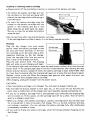
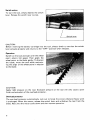
Installing or removing battery cartridge
0
Always switch off the tool before insertion or removal of the battery cartridge.
To remove the battery cartridge, pull out
the set plate on the tool and grasp both
sides of the cartridge while withdrawing it
from the barrel.
0 To insert the battery cartridge, align the
tongue on the battery cartridge with the
groove in the housing and slip it into
place. Snap the set plate back into place.
Be sure to close the s e t plate fully before
using the tool.
0
0
I
Battery cartridge
I
Do not use force when inserting the battery cartridge.
If the cartridge does not slide in easily, it i s not being inserted correctly.
Charging
Plug the fast charger into your power
source. Insert the battery cartridge so that
the plus and minus terminals on the battery cartridge are on the same sides as their
respective markings on the fast charger.
Insert the cartridge fully into the port so
that it rests on the charger port floor.
Press the start button (red). The charging
light will come on and charging will begin.
If the charging light does not come on, press the reset button (yellow) first, then the start
button (red). If the charging light goes out within 10 seconds even after pressing the reset
button and start button a couple of times, the battery cartridge i s dead. (CAUTION : Wait
for more than 5 seconds after the charging light goes out to press the reset button again.)
Replace it with a new one. When the charging light goes out after about one hour, you
may remove the fully charged battery cartridge.
After charging, unplug the charger from the power source.
CAUTION :
Your new battery cartridge is not charged. You will need to charge it before use.
0 Do not keep the button pressed in with tape, etc., or the circuit will not function properly. Also, a malfunction of the charger may result possibly causing overheating, etc.
0 If you try to charge a cartridge from a just-operated tool, sometimes the charging light
will not come on. If this occurs, let the cartridge cool off for a while. Then re-insert it
and try to charge it once more.
0 When you charge a new battery cartridge or a battery cartridge which has not been used
for a long period, it may not accept a full charge. This i s a normal condition and does
not indicate a problem. You can recharge the battery cartridge fully after discharging
it completely a couple of times.
0 If you wish to charge two battery cartridges, allow 15 minutes between chargings on the
fast charger.
0
6
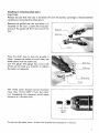
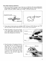
Installing or removing wheel point
CAUTION :
Always be sure that the tool is switched off and the battery cartridge is removed before
installing or removing the wheel point.
Remove the guide from the tool when it is
installed on the tool. Loosen the wing bolt
and pull the guide off the front end of the
tool.
Press the shaft lock to lock the spindle in
place. Loosen the collet nut and insert the
wheel point into the collet nut.
Use the gauge (the gauge has a hex hole
which can be used as a wrench) to tighten
the collet nut securely.
Shaft lock
The wheel point should not be mounted
more than 10 mm (3/8")from the collet
nut. Exceeding this distance could cause
vibration or a broken shaft.
To remove the wheel point, follow the installation procedures in reverse.
7
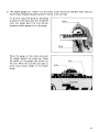
Switch action
CAUTION :
Before inserting the battery cartridge into the tool, always check to see that the switch
lever actuates properly and returns to the “OFF” position when released.
Operation
Switch on the tool and wait until the wheel
point attains full speed. Then apply the
wheel point to the blade gently. To sharpen
the blade, move the tool while maintaining the angle of the wheel point in relation
to the blade.
CAUTION :
Apply light pressure on the tool. Excessive pressure on the tool will only cause a poor
finish and actuation of the overload protector.
Overload protector
The overload protector automatically cuts out to break the circuit whenever heavy work
i s prolonged. When this occurs, release the switch lever and withdraw the tool from the
blade. Wait until the motor cools down and then resume operation.
8
Chain blade sharpening attachment
1. Read the instruction manual of yo':
chain saw to determine the size of wheel point,
the top plate filing angle (30"or 35 ) and the depth gauge clearance [0.025"(0.64mm),
0.030" (0.76mm), 0.035" (0.89mm) or 0.040'(1.02mm)] before use.
1
7
Too d a t e filinq anqle
I
Depth gauge
clearance
2. Three sizes of wheel points are available: 5/32" (4.0mm), 3/16" (4.8mm) and 7/32"
(5.5mm).Select a proper wheel point for chain cutters to be sharpened.
3. Attach the guide to the tool as shown
in the figure after installing the wheel
point. Semi-tighten the wing bolt to the
extent that the guide can be turned.
4. Place the guide on the gauge as shown in
the figure and turn the guide until the
wheel point fits into the appropriate
wheel size slot in the gauge. (The wheel
point will raise up out of the bottom
of the slot by turning the guide counterclockwise). After adjusting the wheel
point to fit into the slot, tighten the
wing bolt securely.
I
Guide
Wheel point
I
9
This will allow approx. 1/5 of the wheel
point diameter to protrude above the
chain cutters as chain manufacturers recommend.
1/5 of wheel point diameter
%
NOTE :
Always check the protrusion of the wheel point using the gauge after tightening the
wing bolt securely because the guide may move when you tighten the wing bolt securely.
Place the wheel point on the chain so
that the wheel point fits into the chain
cutter and the guide line (30"or 35")
on the guide is parallel to the chain.
1
Switch on the tool and wait until the
wheel point attains full speed. Then
move the tool back and forth several
times while maintaining the wheel point
level or a t 10" in relation to the chain.
(Refer to the instruction manual of your
chain saw whether you should maintain
the wheel point level or maintain it a t
Chain
Level
___)
1oo
IO".)
CAUTION :
Place the wheel point on the chain before switching on and remove the wheel point
from the chain after the wheel point has come to a complete stop. Otherwise the rotating wheel point may damage the chain cutters.
10
5. The depth gauges (or "rakers") of the chain cutter should be checked every third or
fourth chain sharpening and lowered if found to be too high.
To do this, place the guide on the gauge
as shown in the figure and turn the guide
Guide
I
until the wheel point fits into the appropriate depth gauge slot in the gauge.
Hang the gauge on the chain and push
the gauge against the guide bar. Place
the guide on the gauge and switch on
the tool. Move the tool left and right to
grind away excess height of the depth
gauge.
Chain
I
Guide
,
11
MAINTENANCE
CAUTION :
Always be sure that the tool is switched off and the battery cartridge is removed before
attempting to perform inspection or maintenance.
To maintain product SAFETY and RELIABILITY, repairs, maintenance or adjustment
should be performed by Makita Authorized or Factory Service Centers, always using
Makita replacement parts.
12
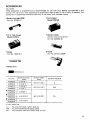
ACCESSORIES
CAUTION :
These accessories or attachments are recommended for use with your Makita tool specified in this
manual. The use of any other accessories or attachments might present a risk of injury t o persons. The
accessories or attachments should be used only in the proper and intended manner.
e Fast charger
e Battery cartridge 9000
Part No. 632007-4
Model DC9100
e 12 V Fast charger
e Battery holster
e
Model DC9012
Holster holds extra battery.
Part No. 823033-3C
Gauge
Part No. 762015-2
Guide
Part No. STEX 122399
e Wheel point
Wheel diameter
(mm)
5 (3/16")
6 (1/4")
5 (3/16")
6 (1/4")
Part No.
741603-8
741604-6
741607-0
741608-8
741622-4
Abrasive material
-
43 (1-11/16")
A
-
43 (1-1 1/16")
WA
46 (1-13/16")
PA
("1
4 (5/32")
74 16 18-5
741623-2
741619-3
741624-0
741620-8
Overall length
4.8 (3/16")
~
-
5.5 (7/32")
e 1/8" shank size
A - To grind mild steel, carbon steel etc.
WA - To grind hardened and special steels.
PA - To grind alloy steel and carbon steel for tool.
13
May-09-89
@-
I
EN
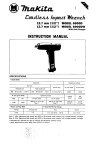
CORDLESS BLADE SHARPENER
Model 903D
Note: The switch and other part configurations
may differ from country to country.
14
MODEL 9 0 3 D
O
“:‘M
1
2
3
4
5
6
7
May-09-89
DESCRIPTION
1
1
1
1
1
1
1
Name Plate
Housing Set lWath Item 11 1
Battery Holder
Switch
Compression Spring 6
Switch Lever
Collet Nut 3
E
‘M
8
9
10
11
12
13
14
DESCRIPTION
1
1
1
1
6
1
1
Note. The switch and other part specificat,ons may differ from country to country.
Collel Body 3 m m
Ball Bearing 607LLB
DC M o t o r 9 6 V
Hou~ingSet IWith Item 21
Pan Head Screw M4x22 IWith Washed
Set Plate
Battery 9000
EN
MAKmA LIMITED ONE YEAR WARRANTY
Warranty Policy
Every Makita tool is thoroughly inspected and tested before leaving the factory. It is warranted to
be free of defects from workmanship and materials for the period of ONE YEAR from the date of
original purchase. Should any trouble develop during this one-year period, return the COMPLETE
tool, freight prepaid, t o one of Makita’s Factory or Authorized Service Centers. If inspection shows
the trouble is caused by defective workmanship or material, Makita will repair (or at our option,
replace) without charge.
This Warranty does not apply where:
repairs have been made or attempted by others:
repairs are required because of normal wear and tear:
The tool has been abused, misused or improperly maintained;
alterations have been made to the tool.
IN NO EVENT SHALL MAKITA BE LIABLE FOR ANY INDIRECT, INCIDENTAL OR CONSEQUENTIAL DAMAGES FROM THE SALE OR USE OF THE PRODUCT. THIS DISCLAIMER
APPLIES BOTH DURING AND AFTER THE TERM OF THIS WARRANTY.
MAKITA DISCLAIMS LIABILITY FOR ANY IMPLIED WARRANTIES, INCLUDING IMPLIED
WARRANTIES O F “MERCHANTABILITY” AND “FITNESS FOR A SPECIFIC PURPOSE,”
AFTER THE ONE-YEAR TERM O F THIS WARRANTY.
T h s Warranty p e s you specific legal rights, and you may also have other nghts which vary from
state to state. Some states do not allow the exclusion or limitation of incidental or consequential
damages, so the above limitation or exclusion may not apply to you. Some states do not allow
limitation on how long an implied warranty lasts, so the above limitation may not apply to you.
~~
- -,u.
11-8.3-chome, Sumiyorhi-cho. Anjo, Aichi 446, Japan
883703 - 061
PRINTED I N JAPAN
1989 - 10 - N