1
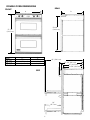
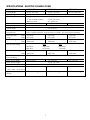
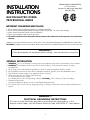
VIKING RANGE CORPORATION
111 Front Street
Greenwood, Mississippi 38930 USA
(662) 455-1200
INSTALLATION
INSTRUCTIONS
BUILT-IN ELECTRIC OVENS
PROFESSIONAL SERIES
IMPORTANT: PLEASE READ AND FOLLOW
1.
2.
3.
4.
5.
Before beginning, please read these instructions completely and carefully.
Do not remove permanently affixed labels, warnings, or plates from product. This may void the warranty.
Please observe all local and national codes and ordinances.
Please ensure that this product is properly grounded.
The installer should leave these instructions with the consumer who should retain for local inspector’s use and for future
reference.
Installation must conform with local codes or in the absence of codes, the National Electrical Code, ANSI/NFPA 70 - latest edition.
IN CANADA: Installation must be in accordance with the current CSA C22.1 Canadian Electrical Codes Part 1 and/or local codes.
WARNING!!!
Frame grounded by a 4-conductor cable assembly. See manufacturer’s instructions
GENERAL INFORMATION
1. WARNING:: The use of cabinets for storage above the appliance may result in potential fire or burn hazard.
2. WARNING:: This appliance shall not be used for space heating. This information is based on safety
considerations.
3. All openings in the wall behind the appliance in the floor under the appliance shall be sealed.
4. Keep appliance area clear and free from combustible materials, gasoline, and other flammable vapors.
5. Disconnect the electric supply to the appliance before servicing.
6. When removing oven for service and/or cleaning
A. Disconnect AC power supply.
B. Carefully remove the oven by pulling outward. CAUTION:: Oven is heavy, use care in handling.
7. Electrical requirements:
Listed in specifications chart p. 4 and 7 under Electrical Requirements.
8. The misuse of the oven doors (e.g. stepping, sitting, or leaning on them) can result in possible hazards and/or
injuries.
WARNING!!!
ELECTRICAL GROUNDING INSTRUCTIONS
This oven must be electrically grounded in accordance with local codes or, in the
absence of local codes, with the National Electrical Code, ANSI/NFPA 70 - latest edition.
1
SINGLE OVEN CUTOUT DIMENSIONS
IN WALL CABINET
Junction
Box
Location
24”
(61.0 cm)
A
28-3/8”
(72.1 cm)
5” Min.
(12.7 cm)
4”
(10.2 cm)
17”
(43.2 cm)
UNDERCOUNTER
Junction
Box
Location
24”
(61.0 cm)
A
28-3/8”
(72.1 cm)
4”
(10.2 cm)
5” Min.
(12.7 cm)
Model
VESO177
VESO107
VESO165
4-3/4” Min.
(12.1 cm)
A
25” (63.5 cm)
28” (71.1 cm)
34” (86.4 cm)
2
SINGLE OVEN DIMENSIONS
FRONT
A
REAR
28-3/4”
(73.0 cm)
B
28-1/4”
(71.8 cm)
Model
VESO177
VESO107
VESO165
A
26-1/2” (67.3 cm)
29-1/2” (75.0 cm)
35-1/4” (89.5 cm)
B
24-3/4” (62.9 cm)
27-3/4” (70.5 cm)
33-3/4” (85.7 cm
43” (109.2 cm)
27-1/4” (68.9 cm)
25” (63.5 cm)
SIDE
23 5/8” (60.0 cm)
18”
(45.7 cm)
3
SPECIFICATIONS-ELECTRIC SINGLE OVEN
DESCRIPTION
VESO177
Overall Width
Overall Height
Overall Depth
26-1/2” 67.3 cm)
Cutout Width
Cutout Height
Cutout Depth
Electrical
Requirements
Maximum Amp
Usage
Preheat Rating
240V
208V
240V
208V
VESO165
29-1/2” (75.0 cm)
35-1/4” (89.5 cm)
28 3/4” (73.0 cm)
To edge of door 25” (63.5 cm)
To end of handle bracket 27 1/4” (68.9 cm)
With door open 43” (109.2 cm)
25” (63.5 cm)
28” (71.1 cm)
34” (86.4 cm)
28-3/8” (72.1 cm)
24” (61.0 cm)
4-wire with ground, 240-208/120 VAC/60 Hz, 30 amp electrical connection.
Unit is equipped with No.10 ground wire in conduit. Should be fused separately.
25.3 amps
25.3 amps
27.3 amps
22.1 amps
22.1 amps
23.8 amps
5750 watts
5750 watts
6250 watts
4315 watts
Broil Element Rating
Bake Element Rating 240V
208V
Convection Cook
Element Rating
Oven Interior Width
Oven Interior Height
Oven Interior Depth
Oven Interior Overall Size
•Three racks / Six positions
Approximate Shipping
Weight
VESO107
Maxi Broil
Mini Broil
2750 watts
2065 watts
20” (50.8 cm)
2.8 cu. ft.
4315 watts
4688 watts
240V
208V
3000 watts
2250 watts
1250 watts
940 watts
2750 watts
3250 watts
2065 watts
2440 watts
240V - 2200 watts
208V - 1650 watts
23” (58.4 cm)
29” (73.7 cm)
16-1/8” (41.0 cm)
15- 3/8” (39.1 cm)
3.3 cu. ft.
4.2 cu. ft.
237 lbs. (106.7 kg)
261 lbs. (117.5 kg)
4
330 lbs. (148.6 kg)
DOUBLE OVEN
CUTOUT DIMENSIONS
24”
(61.0 cm)
A
50-7/8”
(129.2 cm)
Junction Box
Location
5” Min.
(12.7 cm)
4” Min.
(10.2 cm)
Model
VEDO277
VEDO207
VEDO265
15-1/4”
(38.7 cm)
Min. to Floor
A
25” (63.5 cm)
28” (71.1 cm)
34” (86.4 cm)
5
DOUBLE OVEN DIMENSIONS
FRONT
REAR
A
B
50-3/4”
(128.9 cm)
51-1/8”
(129.3 cm)
Model
VEDO277
VEDO207
VEDO265
A
26-1/2” (67.3 cm)
29-1/2” (75.0 cm)
35-1/4” (89.5 cm)
B
24-3/4” (62.9 cm)
27-3/4” (70.5 cm)
33-3/4” (85.7 cm
43” (109.2 cm)
27-1/4” (68.9 cm)
25” (63.5 cm)
23 5/8” (60.0 cm)
SIDE
18”
(45.7 cm)
6
SPECIFICATIONS - ELECTRIC DOUBLE OVEN
DESCRIPTION
VEDO277
Overall Width
Overall Height
Overall Depth
Cutout Width
Cutout Height
Cutout Depth
Electrical
Requirements
Maximum Amp
Usage
Preheat Rating
VEDO207
VEDO265
26-1/2” (67.3 cm)
240V
208V
240V
29-1/2” (75.0 cm)
35-1/4” (89.5 cm)
51-1/8” (129.3 cm)
To edge of door 25” (63.5 cm)
To end of handle bracket 27 1/4” (68.9 cm)
With door open 43” (109.2 cm)
25” (63.5 cm)
28” (71.1 cm)
34” (86.4 cm)
50-7/8” (129.2 cm)
24” (61.0 cm)
4-wire with ground, 240-208/120 VAC/60 Hz, 60 amp connection
Unit is equipped with No.10 ground wire in conduit. Should be fused separately.
50.0 amps
50.0 amps
54.8 amps
44.1 amps
44.1 amps
47.7 amps
11,500 watts
11,500 watts
12,500 watts
208V
8630 watts
8630 watts
Maxi Broil
Mini Broil
2750 watts
2065 watts
240V
3000 watts
1250 watts
2750 watts
2065 watts
240V - 2200 watts
Broil Element Rating
Bake Element Rating 240V
208V
Convection Cook
Element Rating
Oven Interior Width
Oven Interior Height
Oven Interior Depth
Oven Interior Overall Size
•Three racks / Six positions
Approximate Shipping
Weight
20” (50.8 cm)
2.8 cu ft,
360 lbs. (162.0 kg)
7
9376 watts
208V
2250 watts
940 watts
3250 watts
2440 watts
208V - 1650 watts
23” (58.4 cm)
16-1/8” (41.0 cm)
15- 3/8” (39.1 cm)
3.3 cu. ft.
29” (73.7 cm)
402 lbs. (180.9 kg)
575 lbs. (258.8 kg)
4.2 cu. ft.
DOOR REMOVAL /
ADJUSTMENT
Ocassionally, it may be necessary to remove or
adjust the doors. This should only be done by
a qualified techinican. To remove the door,
remove the screws from the top and bottom of
the hinge trim. Open the door to the full open
position. Place a pin in the pinhole on the
hinge. Close the door just until it reaches the
pin in the hinge. Remove the hinge trim. Lift
up and out on the door until the door comes
out of the door socket. Reverse the procedure
to replace the door.
To adjust the door up or down, turn the
adjustment screw. To move the door upward,
turn the adjustment screw clockwise. To move
the door downward, turn the adjustment screw
counterclockwise.
ELECTRICAL REQUIREMENTS
Check your local codes regarding this unit. The single built-in oven requires a 4-wire with ground, 240-208/120
VAC/60 Hz, 30 amp electrical connection. The double built-in ovens require a 4-wire with ground, 240-208/120
VAC/60 Hz, 60 amp electrical connection. This unit is equipped with a No. 10 ground wire in the conduit. See next
section for grounding instructions. It should be fused separately. CAUTION:: Be sure the electric power is off from
the breaker box to the junction box until the oven is installed and ready to operate. The junction box should be
located as shown in the drawing and connected to suitable ground.
Refer to the specification chart for watt rating and recommended amps. House wiring and fusing must comply with
local codes. If no local codes are applicable, wire in accordance with the National Electrical Code, ANSI/NFPA 70latest edition.
ELECTRICAL CONNECTION
With the oven positioned in front of the cabinet opening, connect the wire leads extending from the conduit to
the junction box, making sure the neutral (white) wire is connected to the appropriate terminal. Check your local
code to see which of the options below should be used in grounding the unit.
OPTION 1:
Connect the neutral (white) wire and the grounding (green) wire with the incoming neutral
(white) power supply line.
OPTION 2:
If the junction box is grounded, untwist the grounding (green) wire and attach to the junction
box. Attach the neutral (white) wire to the neutral (white) power supply line.
OPTION 3:
Untwist the grounding (green) wire and attach it to a suitable ground. Attach neutral (white)
wire to the incoming neutral (white) power supply line.
DO NOT USE AN EXTENSION CORD WITH THIS APPLIANCE. SUCH USE MAY RESULT IN A FIRE,
ELECTRICAL SHOCK OR OTHER PERSONAL INJURY.
CHECK WIRING
Connect the electric power at the breaker box and check for proper operation of all functions.
8
PERFORMANCE CHECKLIST
A qualified installer should carry out the following checks:
1. Check oven bake function - bake element on full power, center and outside broil elements at partial power.
Convection bake function - bake and broil element is the same with the convection fan on.
2. Check TruConvecTM function - TruConvecTM element (behind convection fan cover) on and convection fan on.
3. Check mini-broil function - center broil element on.
4. Check maxi-broil function - center and outside broil elements on; convection broil function is the same as maxibroil with the convection fan on.
5. Check self-clean function - Door will lock and in approximately 30 seconds, the center and outside broil elements
will turn on and the bake element will turn on at partial power. Check broil elements through window to make
sure they are on, then abort self-clean cycle to unlock door.
CAUTION:: Do not run self-clean cycle check for more than 10 minutes with oven racks and rack supports inside
oven. This could cause them to discolor due to the high temperature required for self-cleaning.
Any adjustments necessary that are a result of the installer not following instructions will be the responsibility of the
installer, dealer or the end user of the product.
FINAL PREPARATION
1. Some stainless steel parts may have a plastic protective wrap which must be peeled off. All stainless steel body
parts should be wiped with hot, soapy water and with a liquid cleaner designed for this material. If build-up
occurs, do not use steel wool, abrasive cloths, cleaners, or powders!! If it is necessary to scrape stainless steel to
remove encrusted materials, soak with hot, wet cloths to loosen the material, then use a wood or nylon scraper.
Do not use a metal knife, spatula, or any other metal tool to scrape stainless steel! Scratches are almost
impossible to remove.
2. The interior of the oven should be washed thoroughly with hot, soapy water to remove film residues and any
installation dust or debris before being used for food preparation, then rinsed and wiped dry. Solutions stronger
than soap and water are rarely needed.
REPLACEMENT PARTS
Only authorized replacement parts may be used in performing service on the range. Do not repair or replace any
part of the appliance unless specifically recommended in the manual. All other servicing should be referred to a
qualified technician.
9
For connection to the factory installed terminal block, use copper or aluminum
conductors.
WARNING: This unit must be grounded. See Installation Instructions for proper
grounding procedures.
NOTE: Trailers or stripes will be the second color in a color combination. Refer
only to features which are equipped with this unit.
10
For connection to the factory installed
terminal block, use copper or
aluminum conductors only.
WARNING: This unit must be
grounded. See Installation Instructions
for proper grounding procedures.
NOTE: Trailers or stripes will be the
second color in a color combination.
Refer only to features which are
equipped with this unit.
11
VIKING RANGE CORPORATION
111 Front Street • Greenwood, Mississippi 38930 USA • (662) 455-1200
Specifications subject to change without notice.
F20241D
For more product information, call 1-888-VIKING1 (845-4641), or visit the Viking Web site at
http://www.vikingrange.com
(PS0404VR)