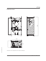
1
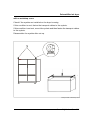
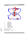
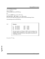
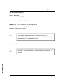
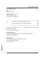
Operating Instructions
Adsorption Dryer
CTT 300
Colortronic GmbH
CTT 300
Colortronic GmbH
Otto-Hahn-Straße 10-14
D-61381 Friedrichsdorf
USA
Colortronic, Inc.
VPR Commerc Center, Suite 406/407
1001 Lower Landing Road
Blackwood, NJ 08012
Telephone (0 61 75) 7 92-0
Telefax (0 61 75) 7 92-1 79
Email [email protected]
Telephone (609) 374-9200
Telefax (609) 374-9311
Email [email protected]
Technical service:
Service department
Telephone: (0 61 75) 7 92-2 22
Telefax: (0 61 75) 7 92-1 19
Email [email protected]
Spare parts department
Telephone: (0 61 75) 7 92-3 33
Telefax: (0 61 75) 7 92-1 08
Edition: 04/98
Order number: 64.10-144GB01
This operation manual is for:
*
* Please fill in personally
Serial number:
Built in:
Date of delivery:
Number of delivery:
Date of commissioning:
Location:
Group of machines:
2
CTT 300
Colortronic GmbH retains all rights to change the information in these operating
instructions at any time without notice.
We assume no liability for any errors or direct or indirect damage resulting in
context with these operating instructions.
Copying, translation or publication in any form except for personal use of
purchaser requires approval from Colortronic GmbH.
All rights reserved.
3
CTT 300
Table of contents
1. Safety instructions (Version: 64.10-0127GB01 10/97) . . . . . . . . . . . . . 1-1
1.1.
1.2.
1.3.
1.4.
Warnings and symbols. . . . . . . . . . . . . . . . . . . . . . . . . . . . . . . . . 1-2
Explanations and information . . . . . . . . . . . . . . . . . . . . . . . . . . . 1-3
For your safety . . . . . . . . . . . . . . . . . . . . . . . . . . . . . . . . . . . . . . . 1-4
For the safety of the devices . . . . . . . . . . . . . . . . . . . . . . . . . . . 1-9
2. Assembly instructions (Version: 64.10-0128GB02 10/97) . . . . . . . . . . 2-1
2.1.
2.2.
2.3.
2.4.
2.5.
Transport. . . . . . . . . . . . . . . . . . . . . . . . . . . . . . . . . . . . . . . . . . . . 2-3
Set-up . . . . . . . . . . . . . . . . . . . . . . . . . . . . . . . . . . . . . . . . . . . . . . 2-5
Mounting of the suction device for regeneration exhaust air . . 2-5
Connection of the return air cooler (optional) . . . . . . . . . . . . . . . 2-6
Electrical connection . . . . . . . . . . . . . . . . . . . . . . . . . . . . . . . . . . 2-7
3. Functional description (Version: 64.10-0145GB01 03/98). . . . . . . . . . 3-1
3.1.
3.2.
3.3.
3.4.
3.5.
3.6.
Dryer . . . . . . . . . . . . . . . . . . . . . . . . . . . . . . . . . . . . . . . . . . . . . . . 3-2
Drying hopper (optional) . . . . . . . . . . . . . . . . . . . . . . . . . . . . . . . 3-3
Return air cooler (optional) . . . . . . . . . . . . . . . . . . . . . . . . . . . . . 3-4
Hopper heaters (optional) . . . . . . . . . . . . . . . . . . . . . . . . . . . . . . 3-5
Automatic motor flaps (optional) . . . . . . . . . . . . . . . . . . . . . . . . 3-5
Connection to a pneumatic conveying system (optional) . . . . . 3-6
4
CTT 300
4. Start-up (Version: 64.10-0130GB04 03/98). . . . . . . . . . . . . . . . . . . . . . . 4-1
4.1. Control system . . . . . . . . . . . . . . . . . . . . . . . . . . . . . . . . . . . . . . . 4-2
4.1.1. Key assignment . . . . . . . . . . . . . . . . . . . . . . . . . . . . . . 4-3
4.1.2. Flow chart . . . . . . . . . . . . . . . . . . . . . . . . . . . . . . . . . . . 4-4
4.2. Switching on the dryer . . . . . . . . . . . . . . . . . . . . . . . . . . . . . . . . . 4-5
4.2.1. Operation statuses . . . . . . . . . . . . . . . . . . . . . . . . . . . . 4-5
4.3. Initial operation . . . . . . . . . . . . . . . . . . . . . . . . . . . . . . . . . . . . . . . 4-6
4.3.1. Setting back the control data (Re-Setting) . . . . . . . . . 4-6
4.4. Passwords . . . . . . . . . . . . . . . . . . . . . . . . . . . . . . . . . . . . . . . . . . 4-7
4.5. Basic parameters . . . . . . . . . . . . . . . . . . . . . . . . . . . . . . . . . . . . . 4-8
4.5.1. Turning the devices on/off . . . . . . . . . . . . . . . . . . . . . 4-8
4.5.2. Entering dryer values . . . . . . . . . . . . . . . . . . . . . . . . . 4-10
4.5.3. Entering hopper values . . . . . . . . . . . . . . . . . . . . . . . 4-13
4.5.4. Observing processing status . . . . . . . . . . . . . . . . . . 4-16
4.5.5. Setting date and time . . . . . . . . . . . . . . . . . . . . . . . . . 4-17
4.5.6. Viewing/changing language and contrast . . . . . . . . . 4-18
4.5.7. Changing parameters. . . . . . . . . . . . . . . . . . . . . . . . . 4-19
4.5.8. Setting the timer . . . . . . . . . . . . . . . . . . . . . . . . . . . . . 4-20
4.6. Recipes (optional) . . . . . . . . . . . . . . . . . . . . . . . . . . . . . . . . . . . 4-21
4.6.1. Editing recipes . . . . . . . . . . . . . . . . . . . . . . . . . . . . . . 4-22
4.6.1.1. Storing the recipe . . . . . . . . . . . . . . . . . . . . 4-23
4.6.1.2. Deleting the recipe . . . . . . . . . . . . . . . . . . . 4-23
4.6.2. Activating the recipe. . . . . . . . . . . . . . . . . . . . . . . . . . 4-24
4.6.3. Printing recipes. . . . . . . . . . . . . . . . . . . . . . . . . . . . . . 4-26
4.7. Starting continuous operation. . . . . . . . . . . . . . . . . . . . . . . . . . 4-27
4.8. Alarm Messages. . . . . . . . . . . . . . . . . . . . . . . . . . . . . . . . . . . . . 4-28
4.9. Viewing system runtime . . . . . . . . . . . . . . . . . . . . . . . . . . . . . . . 4-37
4.10. Switching the dryer off . . . . . . . . . . . . . . . . . . . . . . . . . . . . . . . 4-38
5
CTT 300
5. Maintenance (Version: 64.10-0146GB01 03/98) . . . . . . . . . . . . . . . . . . 5-1
5.1.
5.2.
5.3.
5.4.
5.5.
Maintenance intervals . . . . . . . . . . . . . . . . . . . . . . . . . . . . . . . . . 5-3
Cleaning/renewing the air filters. . . . . . . . . . . . . . . . . . . . . . . . . 5-4
Tensioning the V-belts . . . . . . . . . . . . . . . . . . . . . . . . . . . . . . . . . 5-8
Disposing of the drying agent. . . . . . . . . . . . . . . . . . . . . . . . . . 5-12
Changing the battery of the control system . . . . . . . . . . . . . . . 5-13
6. Technical Data (Version: 64.10-0147GB01 03/98) . . . . . . . . . . . . . . . . 6-1
7. Spare parts list (Version: 64.10-0148GB01 03/98) . . . . . . . . . . . . . . . . 7-1
8. Electrical manual . . . . . . . . . . . . . . . . . . . . . . . . . . . . . . . . . . . . . . . . . . . . 8-1
ID-Number: . . . . . . . . . . . . . . . . . . . . . . . . . . . . . . . . . . . . . . . . . . . . . . . .
9. Accessories. . . . . . . . . . . . . . . . . . . . . . . . . . . . . . . . . . . . . . . . . . . . . . . . . 9-1
¨ .........................................................
¨ .........................................................
¨ .........................................................
6
Dehumidified air dryer
1. Safety instructions
Version: 64.10-0127GB01 10/97
»
These safety instructions apply to all persons within the range of
action of the equipment.
Please inform all persons within the range of action of the
equipment of the direct and indirect hazards connected with the
equipment.
These operating instructions are to be used by all persons
assigned activities connected with the equipment.
Knowledge of the English language is prerequisite.
Ensure in each case that the operating personnel are familiar
with the operating instructions and the function of the
equipment.
Safety instructions 1-1
Dehumidified air dryer
1.1. Warnings and symbols
The following warnings and symbols are used in these operating instructions:
»
This symbol indicates danger to life! Fatal or serious injury is
possible if the corresponding instructions, regulations or
warnings are not observed.
L
This symbol indicates that serious injury is possible if the
corresponding instructions, regulations or warnings are not
observed.
F
This symbol indicates that extensive damage to equipment
is possible if the corresponding instructions, regulations or
warnings are not observed.
&
This symbol indicates information important for becoming
familiar with the equipment, i.e. technical correlations.
$
This symbol indicates that a technical term is explained at
this point.
Safety instructions 1-2
Dehumidified air dryer
1.2. Explanations and information
Various terms and designations are used in these operating instructions to
ensure clarity. Therefore please note that the terms used in the text stand for the
corresponding explanations listed below.
• Equipment
”Equipment” can mean an individual unit, a machine or an installation.
personnel
• Operating
The ”operating personnel” are persons operating the equipment on their own
responsibility or according to instructions.
• Operator
The ”operator” of the equipment (production manager, foreman, etc.) is the
person responsible for all production sequences. The operator instructs the
operating personnel of what is to be done.
instructions
• Operating
The ”operating instructions” describe the interaction of the equipment, production
sequences or methods. The operating instructions must be compiled by the
operator of the equipment.
foreman
• Equipment
When several operating personnel work on one machine, the ”equipment
foreman” coordinates the sequences. The equipment foreman must be
appointed by the operator.
personnel
• Trained
”Trained personnel” are persons who, due to their training, are authorized to carry
out the required work.
Safety instructions 1-3
Dehumidified air dryer
1.3. For your safety
• The operator of this machine must be at least 16 years old.
these operating instructions carefully before the initial start-up. Observe all
• Read
points. Contact us if anything is unclear.
This avoids injury and damage to equipment!
instructions must be stored in such a way that they are available at all times
• These
at the place of operation of the machine.
Danger of accidents arising through improper use!
note that for reasons of clarity not every conceivable case of operation or
• Please
of maintenance can betaken into consideration.
all safety and hazard warnings on the equipment.
• Observe
This avoids injury and damage!
all work on the machine to be carried out only by persons whose
• Allow
qualifications are set out in the relevant chapters of the operating instructions.
Danger of accidents from improper use!
all work carried out on the equipment only the prescribed working clothes
• For
should be worn.
This avoids injury!
the electric supply values with those of the mains supply.
• Compare
Danger of accidents from electric shock!
using lifting gear, please observe the relevant regulations.
• When
Danger of accidents!
note that all installation, start-up and maintenance work is to be carried out
• Please
only by qualified, trained staff.
Danger of accidents from improper use!
Safety instructions 1-4
Dehumidified air dryer
local regulations and requirements pertaining to the equipment must be
• The
observed.
”5 safety rules” as provided in DIN VDE 0105, Section 1, must be observed
• The
for all work carried out on the equipment.
electrical components from the mains supply before work is carried
• Disconnect
out on these components.
Danger to life and limb from electric shock!
not modify, add other equipment or change the design of the equipment
• Do
without the approval of the manufacturer.
Danger of accidents!
detailed operating instructions based on the operating instructions
• Compile
supplied for the sequence of procedures to be carried out on this machine.
Danger of accidents from improper use!
• Appoint a machine foreman to be responsible for the machine.
that the operating staff are thoroughly trained in the operation of the
• Ensure
equipment.
Danger of accidents from improper use!
the machine is switched off for safety reasons, it must be secured against
• Ifunauthorised
activation.
Danger of accidents!
• Before starting maintenance work, appoint a supervisor.
the staff responsible before starting maintenance work.
• Inform
Danger of accidents!
the equipment from the mains supply before starting maintenance
• Disconnect
work to ensure that it cannot be switched on accidentally.
Danger of accidents!
Safety instructions 1-5
Dehumidified air dryer
work may be carried out only by trained staff.
• Repair
Danger of accidents!
operate the equipment when it is partly dismantled.
• Never
Danger! Limbs may be caught in machinery! Electric shock!
machine may only be operated when all the associated components are
• The
properly connected up and in accordance with the relevant regulations.
case of malfunction, shut down the equipment immediately. Have faults
• Incorrected
immediately.
Danger of accidents!
machine is intended only for the drying of granulated plastics. Any other or
• The
additional use is contrary to specifications.
• This machine is not suitable for food-drying.
note that sound levels exceeding 85 db(A) may in the long term damage
• Please
your health. Use the appropriate ear muffs.
This avoids impairment of hearing!
not supplied by Colortronic must be manufactured in accordance
• Attachments
with safety regulation EN 294.
Danger of accidents!
all system sections of the equipment before carrying out any repair
• Depressurize
work.
Caution: Danger of accidents!
pipes, hoses and screwed connections should be checked regularly for leaks
• All
and damage. Any faults which arise should be corrected immediately.
Danger of accidents!
• The safety instructions of the connected machines must be followed.
Safety instructions 1-6
Dehumidified air dryer
air filters should only be cleaned/replaced when the the main switch is off and
• The
the blower has stopped.
This avoids injury and damage to equipment!
operate the dryer without side panels.
• Never
Danger: Limbs may be caught in machinery! Injury through burns!
the v-belts of the blower only when the main switch is switched off and the
• Check
blowers have stopped.
Caution: Danger of accidents!
drying plastics which emit gases dangerous for human health, take care
• When
that the regeneration exhaust air is disposed of without polluting the environment.
that the control system is still under voltage even when the main switch
• Observe
is switched off.
Caution: Danger to life through electrical shock!
note for installation that the equipment is top-heavy.
• Please
Danger exists that it may topple over!
drying hoppers only if they are completely empty.
• Open
Danger of accidents!
open drying hoppers while the device is in operation.
• Never
Danger: Iinjury through burns!
drying hoppers only if they have been cooled down sufficiently.
• Open
Danger: Injury through burns!
any granules remaining on the ground.
• Remove
Danger of accidents!
the wheels after installation if the dryer is mounted on a movable frame.
• Arrest
This will prevent danger to people and material!
Safety instructions 1-7
Dehumidified air dryer
care that the device is not standing on the mains cable.
• Take
This will prevent danger to people and material!
note that the drying cells, drying hoppers and air pipings grow hot during
• Please
use. Avoid touching any of these parts!
Danger: Injury through burns!
Safety instructions 1-8
Dehumidified air dryer
1.4. For the safety of the devices
• Never change settings without carefully assessing the consequences.
• Use only original Colortronic spare parts.
• Observe the maintenance instructions.
• Keep a record of all maintenance works and repairs.
• Please note that electronic components can be damaged by static discharge.
initial operation and in regular intervals, make sure that no electrical
• Before
connections are loose.
• Never readjust sensors without exactly knowing their functions.
ensure that the permitted storage temperature lies between -20 and
• Please
+55 °C (-4 to +131 °F).
ensure that the permitted operation temperature lies between 0 and
• Please
+45 °C (32 to +113 °F).
the direction of rotation of the blowers after the electrical connections have
• Check
been made (see rotational direction arrow).
• Clean the drying hoppers before the first filling.
the instructions of the material manufacturer for the maximum drying
• Note
temperature.
• Note the drying instructions of the material manufacturer.
care that the drying hoppers are always completely filled and that the
• Take
retention period is respected if continual removal is taking place.
Safety instructions 1-9
Dehumidified air dryer
that too large amounts taken from the drying hopper lead to insufficient
• Note
drying of the material.
the air stop valves of drying hoppers which are empty or have not been
• Close
used.
• Note down all data which you have entered into the control system.
• The password is to be entrusted to authorised personnel only.
note that the temperature of the dryer heating system must always be set
• Please
lower than that of the supplementary heaters.
• When you dispose of drying agents, observe all official rules.
• Note that drying cells are replaced or refilled by Colortronic only if they are empty.
material level may not fall below 40 % in the drying hopper, when material is
• The
continuously removed from the drying hopper, but no material is continuously fed
into the drying hopper (batch drying). Close the throttle valves.
• Read the operating manuals of the connected devices.
Safety instructions 1-10
Dehumidified air dryer
2. Assembly instructions
Version: 64.10-0128GB02 10/97
»
These installation instructions are intended for persons with
skills in electrical and mechanical areas due to their training,
experience and received instructions.
Personnel using these installation instructions must be
instructed in the regulations for the prevention of accidents, the
operating conditions and safety regulations and their
implementation.
Ensure in each case that the personnel are informed.
The installation instructions provided in the corresponding
operating instructions apply for all connected equipment.
Observe safety regulations with regard to lifting gear handling
All installation work must be carried out with the equipment
disconnected from electrical power and compressed air supply.
L
For installation work taking place at heights of over approx. 6
feet, use only ladders or similar equipment and working
platforms intended for this purpose. At greater heights, the
proper equipment for protection against falling must be
worn.
Use only suitable lifting gear which is in proper working order
and load suspension devices with sufficient carrying
capacity. Do not stand or work under suspended loads!
Use suitable workshop equipment.
Assembly instructions 2-1
Dehumidified air dryer
F
Install the equipment such that all parts are easily
accessible; this facilitates maintenance and repair work.
Assembly instructions 2-2
Dehumidified air dryer
2.1. Transport
Only use for transport of the dryer a suitable hoist (e. g. a fork lift truck or a
workshop crane).
»
Please ensure adequate carrying capacity of the lifting gear.
Observe dryer weight!
Note that the dryer system is top-heavy. Risc of toppling!
Please observe all safety regulations for the operation of lifting
gear.
with a fork lift truck
Push the forks up to the dryer housing.
Check that the forks reach completely under the dryer housing.
Transport with a fork lift truck
Assembly instructions 2-3
Dehumidified air dryer
with a workshop crane
Check if the eyelets are installed on the dryer housing.
If this condition is met, fasten the transport cables to the eyelets.
If this condition is not met, mount the eyelets and then fasten the transport cables
to the eyelets.
Disassemble the eyelets after set-up.
Transport with a workshop crane
Assembly instructions 2-4
Dehumidified air dryer
2.2. Set-up
A special foundation is not required for installation.
The dryer must be installed on a level surface, and may not be exposed to
excessive humidity. Maximum permissible ambient temperature of the control
system is 45°C.
To facilitate servicing, install the dryer such that it is accessible from 3 sides.
Make sure that the air filters can be changed without problems. The rear of the
dryer can be placed against a wall.
»
The main switch must be freely accessible.
To conserve energy, keep the distances between dryer, hopper and processing
machine as short as possible.
2.3. Mounting of the suction device for regeneration exhaust air
When plastics are dried which produce hazardous gases, environmentally sound
disposal of the regeneration exhaust air must be provided. The throughput of the
regeneration blower may not be changed.
It must be taken into consideration when installing a disposal system (e.g.
exhaust system) that regeneration exhaust air is extremely humid. This may
result in condensation water which must not enter the dryer again under any
circumstances.
Assembly instructions 2-5
Dehumidified air dryer
2.4. Connection of the return air cooler (optional)
F
A return air cooler is generally required in cases in which the
return air temperature is over 65°C.
The return air cooler can be connected to a coolant circuit or the water mains
network.
Observe the water flow with connection to water mains network. The coolant
circuit must be dimensioned acccordingly.
Remove the side panel of the dryer.
Connect the coolant intake line and coolant return line to the return air cooler.
Obeserve the flow direction of the coolant through the return air cooler.
Check the connections for leaks.
Mount the side panel.
Assembly instructions 2-6
Dehumidified air dryer
2.5. Electrical connection
»
Observe the rules of the local electricity board.
Check that the supply voltage and the power frequency are in
accordance with the data on the name plate of the device.
The electrical connection may only be carried through or
assigned by Colortronic service staff or by qualified staff
authorized by Colortronic.
Other persons are not permitted to carry through the electrical
connection.
L
Observe that the control system is still under voltage even
when the mains switch is switched off.
F
Regularly make sure that none of the electrical or screw
connections are loose.
Immediately after connection, check the direction of rotation
of the blowers (see rotational direction arrow on the
blowers).
The direction of rotation should be switched in the supply line
only.
The operation voltage is 400 V/3AC/PEN/50 Hz.
Special operation voltages are possible.
Assembly instructions 2-7
CTT 300
3. Functional description
Version: 64.10-0145GB01 03/98
»
This functional description is intended for all operating
personnel of the equipment.
Prerequisite for this functional description is general knowledge
of dryers and SPS systems.
Ensure in each case that the operating personnel are
sufficiently informed.
Functional description 3-1
CTT 300
3.1. Dryer
The dryer operates with dehumidified air, i.e. the air is not only heated but also
dehumidified before flowing into the drying hopper. This principle allows plastic
granules to be dried to a residual moisture content as low as 0.002 % (PET
granulate).
The dew point temperature of the dehumidified air lies between -55°C and,
depending on the set value, -35 to -28°C. The lower limiting value of the
dehumidified air is about 80°C due to the intake of water in the drying cells.
The dryer operates continuously, i.e. dehumidified and, if necessary, heated air
is produced continuously.
F
The dryer is designed for continuous operation.
The dryer operates with 2 drying cells; one of these cells is always in the drying
cycle while the other is being regenerated (max. 60 min.).
The dew point temperature is monitored continuously. The valve system
switches to the freshly regenerated drying cell only after the selected dew point
temperature has been reached. The humid drying cell is then regenerated. After
the cooling time the drying cell is ready for operation again. The valve system
switches to the freshly regenerated drying cell only after the moisture content of
the drying cell which is in the drying cycle has reached the setpoint value.
If a malfunction occurs in the drying cycle during the program run, regeneration is
not interrupted, but continues until the program end has been reached. This
guarantees that 1 regenerated drying cells is always available.
The air inside the switch cabinet is cooled by a cooling appliance for the
protection of temperature-sensitive components (if present, optional).
With the digital timer the dryer can be switched on and off at set times.
Functional description 3-2
CTT 300
3.2. Drying hopper (optional)
The material is dried in the drying hopper. The dehumidified air (2) is forced
through the material in the hopper, collecting moisture in the process. The drying
hopper must be dimensioned according to its intended use to ensure that the final
moisture content is attained. When the hopper is filled for the first time or at the
start of a drying procedure, the material in the hopper must be dried completely
before material can be removed from the hopper for the first time.
When material is continuously removed from the hopper, material must also be
continuously fed into the drying hopper. The new (moist) material is fed into the
drying hopper from the top and slowly moves downward toward the material
suction box. As the material moves upward, it is dried until its final moisture
content is attained.
If several drying hoppers are connected to one dryer, the feed and return pipes
are each equipped with a throttle valve by means of which air volume can be
regulated. The feed opening and material temperature can be read at the control
system (optional).
Flow indicators are available as auxiliary equipment; these allow comparison of
the air flow in the individual drying hoppers.
To ensure proper continuous drying, we recommend that the drying hopper
always is kept completely filled. Automatic conveyors, such as the models
included in our delivery program, optimize the automation of the material flow.
F
When material is continuously removed from the hopper, but
no material is continuously fed into the drying hopper (batch
drying), the material level may not fall below 40 %.
Close the throttle valves.
Functional description 3-3
CTT 300
3.3. Return air cooler (optional)
F
A return air cooler is generally required in cases in which the
return air temperature is over 65°C.
A return air cooler improves the efficiency of the drying cells.
The return air cooler reduces the return air temperature to a defined value.
The return air temperature is set at the operation panel.
&
The lower the value chosen for the return air temperature,
the better the efficiency of the drying cells.
The dryer is automatically switched off if temperature
exceeds 80°C.
Return air temperature is continuously monitored; the return air cooler is
activated only when needed. If the return air temperature exceeds the set value
(e.g. due to interruption in the cooling water supply or soiling), an alarm message
is given.
The return air cooler can be connected to a coolant circuit or to the water mains
network.
Functional description 3-4
CTT 300
3.4. Hopper heaters (optional)
If differing drying temperatures are required in the different drying hoppers,
hopper heaters must be installed on the drying hoppers. The drying temperature
of each drying hopper can be set centrally at the dryer.
3.5. Automatic motor flaps (optional)
Automatic motor flaps cut off the drying hopper from the drying circuit as soon as
the material is completely dried. The supplementary heating system is also
switched off. Dehumidified air flows into the drying hopper only after new, moist
material is added to the hopper. This ensures that the material is not damaged,
and saves a considerable amount of energy.
Temperature probes at the feed opening of the drying hopper and inside the
drying hopper enable comparison of feed opening and material temperature,
from which the drying degree of the material can be calculated.
If the drying hopper is to be cleaned or blocked, the motor flap can be closed via
the dryer. The supplementary heating system is then automatically switched off.
Functional description 3-5
CTT 300
3.6. Connection to a pneumatic conveying system (optional)
The dryer operates most effectively in conjunction with a pneumatic conveying
system. This combination of dryer and conveying system ensures that sufficient
material is always fed into the drying hopper.
Only the amount of material required for the processing machines used is
removed from the hopper. This guarantees that the final drying result remains
constant.
Colortronic drying hoppers are available equipped with the corresponding flange
for connection of a Colortronic pneumatic conveyor directly ex works.
Suction boxes can also be delivered with the required number of suction tubes.
These suction boxes were developed specially for this hopper to prevent dust and
foreign particles from being aspirated into the system.
A device for connection to the dehumidified air supply line is also available.
Please note that the function of this combination is different from that of the
conventional Colortronic suction boxes.
If the suction box is located under the drying hopper, flow in the feed line is
decreased by pulling out the suction tube. Conveying capacity is increased by
pushing in the suction tube.
Functional description 3-6
Dehumidified air dryer
4. Start-up
Version: 64.10-0130GB04 03/98
»
This chapter is directed at the operators of the equipment.
This chapter assumes general skills in dealing with dryers and
SPS systems.
This chapter assumes that the functional description has been
read and understood.
It should be ensured in each and every case that the operators
have the relevant skills.
F
Note down all set values of the control system.
Make sure that the cooling appliance is connected to the
mains socket in the electrical cabinet (if present, optional).
Make sure that any condensate penetrating from the cooling
appliance (optional) does not get inside the dryer or the
control box.
&
If the inside temperature of the switch cabinet is above
+50°C, the dryer is switched off after 30 minutes if it is
operated with a cooling appliance (optional).
Start-up 4-1
Dehumidified air dryer
4.1. Control system
The control system is switched on at the main switch. The control system is
operated via a ”selection window” and the keyboard of the operator panel.
The facility’s control system is factory-programmed. Nevertheless, you have to
set specific values (basic parameters) which are dependent on the processed
material, for instance.
The values entered are stored in the control system and remain so, even after the
unit is switched off or in the event of a power cut. All messages are displayed in
plain text.
In describing this start-up, we have assumed that the various sub-menus are
selected from the ”table of contents”.
This structure of the description has been selected since, in most cases, you will
only work on one item in the ”submenu”.
If you want to work on several ”submenu” items in succession, you can select the
individual items directly by means of the arrow keys.
The control system is designed for connection of one dryer, a maximum of 10
hopper heaters (optional), 10 motor flaps (optional), and one bypass flap
(optional).
Dew point is monitored continuously; dew point temperature is displayed.
Supplementary heating systems are operated directly via the dryer control
system.
All heating systems are equipped with temperature limiters which reliably prevent
overheating.
The control system is communication-capable (optional); a printer can also be
connected (optional).
The individual states of operation are indicated by means of a flow chart with
symbols and LED’s.
Start-up 4-2
Dehumidified air dryer
4.1.1. Key assignment
F1-key:
Leads to the table of contents.
ENTER-key:
Confirms the entries.
ESC-key:
Goes back one step in the menu.
ACK-key:
Activates an alarm message;
to unblock the control system.
Arrow keys:
Move the cursor bar;
switch the appliances on or off in combination with
the SHIFT key;
for scrolling forward or backward in a menu.
SHIFT-key:
Switches on the secondary functions of the keys,
when the SHIFT-key has been pushed, the
LED “SHIFT” is on.
HELP-key:
Viewing additional texts,
when additional texts can be viewed the
LED “HELP” is on.
LED “ALARM”:
A failure is given by flashing of the LED “alarm”.
If the alarm message is acknowledged by pressing
of the “ACK” key, but the failure is not yet eliminated,
the flashing changes to steady light.
When there is no failure the LED is off.
&
LED = light emitting diode
An additional alarm device (horn or lamp) can be connected
(optional).
Start-up 4-3
Dehumidified air dryer
4.1.2. Flow chart
4
5
6
7
3
2
1
2
3
10
1
2
3
4
5
6
7
8
9
10
9
8
Indicator lamp
Valve system
Drying chamber
Drying blower
Return air filter
Drying hopper
Drying heater
Regeneration heater
Regeneration blower
Regeneration air filter
Indicator lamp messages:
Green continous light:
Red continous light:
in process
alarm
Start-up 4-4
Dehumidified air dryer
4.2. Switching on the dryer
Switch on the system by means of the main switch.
&
The control system carries through a self-test; after that, the
name of the dryer and the operation status of the unit are
displayed.
F
Unblock the control system:
Keep the ACK key pressed until the LEDs of the keys K1 - K4
light up.
4.2.1. Operation statuses
The following operation statuses can be displayed:
• system is off
• system is on
• blower runs on
• valve block
• regeneration will be finished in x min.
Start-up 4-5
Dehumidified air dryer
4.3. Initial operation
&
Before initial operation, all control data should be set back.
»
This work may be carried through only by qualified personnel
trained in the field of electrical engineering.
4.3.1. Setting back the control data (Re-Setting)
Open the control box by means of the control box key which is part of the supply.
Set the function selector (10) at ”STOP” position.
Open the battery compartment (1) of the control system and take out the battery.
Set the on/off switch (4) at position ”0".
Wait for approx. 30 seconds.
Control
Start-up 4-6
Dehumidified air dryer
&
All control data are set back to the standard settings.
Set the on/off switch (4) at position ”1".
Insert the battery into the battery compartment (1).
Close the battery compartment (1).
Set the function selector (10) at ”RUN” position.
Close the control box.
F
Unblock the control system:
Keep the ACK key pressed until the LEDs of the keys K1 - K4
light up.
4.4. Passwords
The entry of a password prevents unauthorised persons from having access to
the data entered into the control system. Important data can then be entered or
modified only after the password has been entered.
If you make no entries for more than 10 minutes, the access is blocked and you
have to re-enter the password.
• password level 6: 79 21 54
F
Tell the password only to authorised persons.
Start-up 4-7
Dehumidified air dryer
4.5. Basic parameters
Press the ”F1"-key.
4.5.1. Turning the devices on/off
Select ”Main menu”.
Acknowledge with the ENTER-key.
or
Press the ”F2”-key.
Dryer on/off
”on” = turn dryer on,
”off” = turn dryer off.
Acknowledge with the ENTER-key.
Timer on/off
Press the SHIFT-key and choose with the arrow-keys the desired operation:
”internal” = operation with timer (operation at OP7, see chapter timer),
“external” = operation with timer (if present),
”off” = operation without timer.
Acknowledge with the ENTER-key.
&
The timer is only operating, when the dryer is switched on.
Drying Heater on/off (optional)
”on” = turn drying ht. on,
”off” = turn drying ht. off.
Acknowledge with the ENTER-key.
Start-up 4-8
Dehumidified air dryer
Return air cooler on/off (optional)
“on” = operation with return air cooler,
“off” = operation without return air cooler
Acknowledge with the ENTER-key.
Hopper X on/off (optional)
(X = number of the drying hopper)
“on” = releasing drying hopper X,
“off” = blocking drying hopper X
Acknowledge with the ENTER-key.
Hopper heater X on/off (optional)
(X = number of the hopper heater)
“on” = switch on hopper heater X,
“off” = switch off hopper heater X
Acknowledge with the ENTER-key.
Press the ”F1"-key.
Start-up 4-9
Dehumidified air dryer
4.5.2. Entering dryer values
Select ”Dryer”.
Acknowledge with the ENTER-key.
or
Press the ”F3”-key.
Drying Heater Target (optional)
Enter the drying temperature of the dryer.
F
Observe max. drying temperature of the dryer.
The drying temperature of the dryer must be selected so that
it is the same as or higher than the desired hopper
temperature.
Turn off the dryer heating system if a lower drying heat is
entered.
Acknowledge with the ENTER-key.
Drying Heater Act. (optional)
The current drying temperature will be displayed.
Regeneration Heater Act.
The regenerated heat temperature will be displayed.
Used air Act.
The current temperature of the used air will be displayed.
Start-up 4-10
Dehumidified air dryer
Return air cooler Target (optional)
Enter the max. permissible return air temperature (65°C max.). Higher
temperatures are not allowed.
Acknowledge with the ENTER-key.
Return air cooler Act. (optional)
The current return air temperature will be displayed.
&
The cooling effect of the return air cooler is highly dependent
on the cooler circuit.
The lower the value chosen for the return air temperature,
the better the efficiency of the drying cells.
F
Plan the size of the coolant circuit accordingly.
Start-up 4-11
Dehumidified air dryer
Dew point max.
Enter the maximum permissible (worst allowed) dew point temperature
(-35 to 28°C).
Acknowledge with the ENTER-key.
Dew point Act.
The current dew point temperature will be displayed.
&
If there is a cable break “+0 °C” is displayed.
Press the ”F1"-key.
Start-up 4-12
Dehumidified air dryer
4.5.3. Entering hopper values
Select ”Hopper”.
Acknowledge with the ENTER-key.
or
Press the ”F4”-key.
Hopper entry X Target
(X = number of the drying hopper)
Enter the drying temperature for hopper flap X (when operating with
supplementary heating).
Acknowledge with the ENTER-key.
Hopper entry X Act.
(X = number of the drying hopper)
The current temperature at the feed opening of hopper flap X will be displayed.
&
If there is a cable break “+0 °C” is displayed.
F
The lowest drying temperature setting of the hopper flap
must be the same as or higher than the drying temperature.
Start-up 4-13
Dehumidified air dryer
Granules X
desired: _ % = _ °C
(X = number of the drying hopper)
Enter the material temperature at which the flap (optional) on the drying hopper X
should close.
&
This value is entered in percent of the temperature on the
hopper inlet.
The material temperature calculated by the control system
for closing the flap on the drying hopper X is displayed in °C.
Confirm with the ENTER key.
Granules X
actual: _ °C
(X = number of the drying hopper)
The current material temperature in the drying hopper X is displayed in °C
(optional, if there is a flap).
Start-up 4-14
Dehumidified air dryer
Granules X
dwelling time: _ min
The dwelling time of the material within the drying hopper X is displayed in
minutes.
F
Observe the indicated dwelling time.
&
When the drying hopper is released, the dwelling time starts.
The residual time is displayed (= current dwelling time).
If the drying hopper is blocked, the current dwelling time is
reset to the value of the dwelling time which has been
entered before.
Press the ”F1"-key.
Start-up 4-15
Dehumidified air dryer
4.5.4. Observing processing status
Select ”Status”.
Acknowledge with the ENTER-key.
or
Press the ”K1”-key.
&
The current operation status of individual assembly parts is
displayed:
e.g.: valve block moved in/moved out/error
“moved in” = The upper drying cells are within the drying
circuit; the lower ones are regenerated.
“moved out” = The upper drying cells are regenerated; the
lower ones are within the drying circuit.
“error” = An error has occurred.
Other operation statuses:
“on” = in operation,
“off” = out of operation,
“open” = opened,
“shut” = closed.
Press the “F1"-key.
Start-up 4-16
Dehumidified air dryer
4.5.5. Setting date and time
&
This function is password protected.
Press the “K3"-key.
Enter the password if requested.
Date
Press the SHIFT key.
By means of the arrow keys, select the desired week-day.
By means of the arrow keys, select the shown date.
Press the SHIFT key.
Enter the desired date.
Press the ENTER key.
Time
Enter the desired time.
Press the ENTER key.
Press the ”F1”-key.
Start-up 4-17
Dehumidified air dryer
4.5.6. Viewing/changing language and contrast
&
This function is password protected.
Press the “K4"-key.
Enter the password if requested.
Contrast
Press the SHIFT key.
By means of the arrow keys, select the adjustment which suits you best.
Press the ENTER key.
&
Depending on the outside temperature, the brightness of the
screen may vary.
Language
Press the SHIFT key.
By means of the arrow keys, select the desired language (if present).
Press the ENTER key.
Press the “F1"-key.
Start-up 4-18
Dehumidified air dryer
4.5.7. Changing parameters
Select ”Parameters”.
Acknowledge with the ENTER-key.
or
Press the SHIFT-key and the ”K1”-key.
F
The values in this menu may only be changed after
contacting Colortronic Service.
Press the ”F1"-key.
Start-up 4-19
Dehumidified air dryer
4.5.8. Setting the timer
Select ”Timer”.
Acknowledge with the ENTER-key.
or
Press the SHIFT-key and the ”F1”-key.
XX ON 00:00 OFF 00:00 (XX = day Mo-Su)
Enter for each day the switching on time and the switching off time.
Acknowledge with the ENTER-key.
&
Example:
Fr
Sa
Su
Mo
ON
ON
ON
ON
08:00
00:00
20:00
00:00
OFF
OFF
OFF
OFF
23:59
23:59
08:00
00:00
The dryer starts on Friday at 08:00 in the morning, runs
through without interruption until sunday at 08:00 and
switches off. At 20:00 the dryer starts again and switches off
on Monday at 00:00.
Press the ”F1"-key.
Start-up 4-20
Dehumidified air dryer
4.6. Recipes (optional)
Select “Recipes”.
Confirm with the ENTER-key.
or
Press the keys “Shift” and “F3“.
Hopper no. X (X = number of the drying hopper)
Enter the number of the drying hopper whose recipe you want to edit.
Confirm with the ENTER-key.
&
The hopper is displayed with the current recipe Y, Z
(Y = recipe value range, Z = recipe number), drying
temperature (°C) and dwelling time.
Press the “↓” key.
&
Recipes can be modified (stored/deleted), activated or
printed.
Start-up 4-21
Dehumidified air dryer
4.6.1. Editing recipes
Edit
Press the “F2"-key.
Recipe range X (X = 1 - 4)
Select the recipe range.
Confirm with the ENTER-key.
&
99 recipes can be stored per recipe range.
During initial operation, no recipes are stored.
By means of the arrow keys “↓” or “↑”, select the desired recipe or enter the
desired recipe number.
Confirm with the ENTER-key.
Drying temperature
Enter the drying temperature in °C for the material in hopper X.
Confirm with the ENTER-key.
Dwelling time
Enter the dwelling time of the material in minutes.
Confirm with the ENTER-key.
Press the ESC-key.
Start-up 4-22
Dehumidified air dryer
4.6.1.1. Storing the recipe
No.
Enter a recipe number.
Confirm with the ENTER-key.
Name
Enter a name for the recipe.
Confirm with the ENTER-key.
Store data record? Y
Confirm with the ENTER-key if you want to save the recipe.
Press the ESC-key if you do not want to save the recipe.
&
If the recipe number has already been entered into the recipe
memory, a security prompt is carried through.
4.6.1.2. Deleting the recipe
By means of the arrow keys “↓” or “↑”, select the desired recipe or enter the
desired recipe number.
Press the “DEL”-key.
Delete?
Confirm with the ENTER-key if you want to delete the recipe.
Press the ESC-key if you do not want to delete the recipe.
Press the ”F1"-key.
Start-up 4-23
Dehumidified air dryer
4.6.2. Activating the recipe
Press the keys “Shift” and “F3“.
Hopper no. X (X = number of the drying hopper)
Enter the number of the drying hopper whose recipe you want to activate.
Confirm with the ENTER-key.
Press the “↓” key.
Transfer
Press the “F3"-key.
Recipe range X (X = 1 - 4)
Select the recipe range.
Confirm with the ENTER-key.
Source
Enter the recipe number or press the SHIFT-key and select the desired recipe by
means of the arrow keys “↓” or “↑”, respectively.
Confirm with the ENTER-key.
&
The name of the recipe is displayed.
Start-up 4-24
Dehumidified air dryer
Destination
Enter “0" if you want to activate the recipe.
Confirm with the ENTER-key.
&
Enter a number between 1 and 99 if you want to store the
recipe under a new recipe number.
Assumption
Confirm with the ENTER-key in order to transfer the recipe to the control system.
&
When the recipe has been transferred, a “*” is displayed.
OP: X (X = 1 - 4)
The recipe range is displayed.
Press the “F1"-key.
Start-up 4-25
Dehumidified air dryer
4.6.3. Printing recipes
F
Make sure that a printer (optional) has been connected and
is switched on.
Press the keys “Shift” and “F3“.
Press the “↓” key twice.
Select the recipe range (1-4) and press the key “F2" (= recipe range 1 and 3) or
”F3" (= recipe range 2 and 4), respectively.
F
The recipes are printed.
Press the “F1"-key.
Start-up 4-26
Dehumidified air dryer
4.7. Starting continuous operation
When you have carried through all basic settings, you can start with continuous
operation.
&
For initial operation: set back the control data (Re-Setting
and unblock the control system.
Make sure that hoppers which are not in use are separated
from the dehumidified air supply.
Make sure that the set drying temperatures are suited for the
materials in the hoppers.
After first filling, do not process the material until after the
dwelling time.
If a return air cooler is installed, switch on the coolant circuit
of the return air cooler.
Make sure that the cooling appliance is connected to the
mains socket (if present, optional).
Check setting of the timer.
Select ”Main menu”.
Acknowledge with the ENTER-key.
or
Press the ”F2”-key.
Select ”Dryer on”.
Acknowledge with the ENTER-key.
Start-up 4-27
Dehumidified air dryer
4.8. Alarm Messages
&
Alarm messages are displayed in plain language on the
screen of the operator device.
The display of alarm messages in the operator device can
only be erased by pressing the ”ACK” key. The failure is not
repaired.
A failure is given by flashing of the LED “alarm”. If the alarm
message is acknowledged by pressing of the “ACK” key, but
the failure is not yet eliminated, the flashing changes to
steady light.
If a cooling appliance is present: If the temperature inside the
switch box is higher than +50 C, the lamp ”alarm temperature inside switch box” goes on. If the temperature is
still too high after 30 minutes, the dryer is switched off.
o
F
Failures must be repaired immediately.
Press the ”K2"-key.
Start-up 4-28
Dehumidified air dryer
View
Press the ”F2"-key.
All alarm messages with their numbers (see Texts), date, time and the
supplement ”K”, ”G”, or ”Q” are displayed.
&
”K” = coming (a failure occured)
”G” = going (the resent for the failure has gone)
”Q” = reset (the display of the alarm message in the
operator device has been erased by pressing the
”ACK”-key)
Press the ESC-key.
Print (Optional)
&
This function is password protected.
F
Make sure that a printer is connected and switched on.
Press the ”F3"-key.
The alarm messages are printed.
Press the “↓” -key.
Start-up 4-29
Dehumidified air dryer
Number
Press the ”F2"-key.
Total messages
The number of all alarm messages is displayed.
Waiting messages
The number of current alarm messages is displayed.
Press the ESC-key.
Delete
Press the ”F3"-key.
&
This function is password protected (Colortronic service).
Press the ENTER-key for deleting the messages.
Press the ESC-key.
Press the “↓” key.
Start-up 4-30
Dehumidified air dryer
Overflow
Press the ”F2"-key.
&
If there are more current alarm messages than can be saved,
a warning message (= residual buffer reached) may be
given.
This function is password protected (Colortronic service).
Overflow warning On/Off
Press the SHIFT-key.
By means of the arrow keys, select ”on” if a warning message is to be given.
By means of the arrow keys, select ”off” if no warning message is to be given.
Press the ENTER-key.
Press the ESC-key.
Start-up 4-31
Dehumidified air dryer
Text
Press the ”F3"-key.
All possible alarm messages are displayed with their numbers (see Viewing).
For viewing the possible alarm messages, press the arrow keys:
PLC (= SPS) Battery is Empty
Replace the SPS battery.
Main Switch is Off
The main switch has been placed in the off position.
The safety temperature limiter of the drying or the regeneration heater,
respectively, has been activated.
The safety temperature limiter of a hopper heater has been activated.
Error valve block.
Check the safety temperature limiter.
Check the position of the valve block.
A Safety Temperature Limiter has been Activated
Check the safety temperature limiter of the drying, regeneration, or hopper
heater, respectively.
Filter Door is Open
The side panels to the air filters are open.
Assemble side panels.
The Safety Switch Regeneration Blower Has Been Actuated
Check the blower.
Check the fuses.
Short circuit check of the blower.
Start-up 4-32
Dehumidified air dryer
Vacuum Regeneration Blower
The regeneration blower does not produce sufficient pressure.
Check the blower.
Vacuum sensor defective.
The Safety Switch Drying Blower Has Been Actuated
Check the blower.
Check the fuses.
Short circuit check of the blower.
Vacuum Drying Blower
The drying blower does not produce sufficient pressure.
Check the blower.
Vacuum sensor defective.
Temperature Measurement Regeneration Heater Defective
Check the cables and the sensor.
Check the power supply.
Short circuit check.
Excess Temperature Regeneration Heater
The regeneration temperature is too high.
Check the safety temperature limiter.
Colortronic Service.
Insufficient Temperature Regeneration Heater
The regeneration temperature is too low.
Check the regeneration heater.
Start-up 4-33
Dehumidified air dryer
The Safety Switch Regeneration Heater Has Been Actuated
Check the heater.
Check the fuses.
Short circuit check of the heater.
Error Bypass Flap
The bypass flap does not close or closes too slowly.
Check the bypass flap.
Error Valve Block
The valve block has not reached the proper position. The main switch is placed in
the off position.
Check the position of the valve block. Press the “ACK” key and put the main
switch in the on position immediately. If the valve block has not reached the
correct position within 1 minute, the main switch is again placed in the off position.
Colortronic Service.
Temperature Measurement Outgoing Air Defective
Check cables and sensor.
Temperature Measurement Return Air Defective
Check cables and sensor.
Excess Temperature Return Air
Check cables and sensor.
Check the return air cooler.
Temperature Measurement Drying Heater Defective
Check cables and sensor.
Check the power supply.
Short circuit check.
Start-up 4-34
Dehumidified air dryer
Excess Temperature Drying Heater
The drying temperature is too high.
Check the safety temperature limiter.
Colortronic Service.
Insufficient Temperature Drying Heater
The drying temperature is too low.
Check the drying heater.
Safety Switch Drying Heater
Check the heater.
Check the fuses.
Short circuit check of the heater.
Temperature Measurement Heater Defective Hopper X
(X = number of the drying hopper)
Check cables and sensor.
Check the power supply.
Short circuit check.
Excess Temperature Heater Hopper X
(X = number of the drying hopper)
The temperature of the hopper heater is too high.
Check the safety temperature limiter.
Colortronic Service.
Insufficient Temperature Heater Hopper X
(X = number of the drying hopper)
The temperature of the hopper heater is too low.
Check the hopper heater.
Start-up 4-35
Dehumidified air dryer
Safety Switch Heater Hopper X
(X = number of the drying hopper)
Check the heater.
Check the fuses.
Short circuit check of the heater.
Temperature Measurement Granules Defective Hopper X
(X = number of the drying hopper)
Check cables and sensor.
Check the power supply.
Short circuit check.
Excess Temperature Granules Hopper X
(X = number of the drying hopper)
The material temperature is too high.
Check the heater.
Check the throttle valve.
Valve Error Hopper X
(X = number of the drying hopper)
The throttle valve does not close or closes too slowly.
Check the throttle valve.
Press the “F1"-key.
Start-up 4-36
Dehumidified air dryer
4.9. Viewing system runtime
Select ”System runtime”.
Acknowledge with the ENTER-key.
or
Press the SHIFT-key and the ”F2”-key.
System runtime
XX h YY min
&
The runtime of the blowers is shown in hours and minutes.
Start-up 4-37
Dehumidified air dryer
4.10. Switching the dryer off
Select ”Main menu”.
Acknowledge with the ENTER-key.
or
Press the ”F2”-key.
Select ”Dryer off”.
Acknowledge with the ENTER-key.
L
Wait until the regeneration phase is finished and the blower
has come to a standstill.
Switch off the dryer at the main switch.
Disconnect the power supply.
F
Never switch off the dryer directly at the main switch.
Start-up 4-38
CTT 300
5. Maintenance
Version: 64.10-0146GB01 03/98
»
This chapter is intended for persons with skills in electrical and
mechanical areas due to their training, experience and received
instructions.
Personnel using the instructions in this chapter must be
instructed of the regulations for the prevention of accidents, the
operating conditions and safety regulations and their
implementation.
Ensure in each case that the personnel are informed.
For maintenance work taking place at heights of over approx. 6
feet, use only ladders or similar equipment and working
platforms intended for this purpose. At greater heights, the
proper equipment for protection against falling must be worn.
Use only suitable lifting gear which is in proper working order
and load suspension devices with sufficient carrying capacity.
Do not stand or work under suspended loads!
Ensure that the electric motors/switch cabinets are sufficiently
protected against moisture.
Use only suitable workshop equipment.
Before starting maintenance work, appoint a supervisor.
Inform the responsible personnel before maintenance work on
the system is started.
Never operate the equipment when partially dismantled.
All maintenace and repair work not described in this chapter,
may only be carried out by Colortronic service personnel or
authorized personnel (appointed by Colortronic).
Maintenance 5-1
CTT 300
L
Disconnect the equipment from mains supply before starting
maintenance procedures to ensure that it cannot be
switched on unintentionally.
Depressurize all compressed air piping of the equipment
before starting maintenance work.
F
Please observe the maintenance schedule.
Before starting maintenance work, clean the equipment of
oil, fuel or lubricants.
Ensure that materials and incidentals required for operation
as well as spare parts are disposed of properly and in an
environmentally sound manner.
Use only original Colortronic spare parts.
Keep record of all maintenance and repair procedures.
Maintenance 5-2
CTT 300
5.1. Maintenance intervals
Daily:
Check warning signs on equipment for good
legibility and completeness
Clean return air filter and housing
(depending on amount of dust collected)
Lamp test: if you press the ”+/-”-button longer than
2 seconds all LED’s must light up
Weekly:
Check function of the main switch
Clean filter of the electrical cabinet
(depending on amount of dust collected)
Monthly:
Check V-belt tension of blower
Every three months:
Clean filter of the regeneration blower
(depending on amount of dust collected)
Every six months:
Exchange return air filter
(depending on amount of dust collected)
Exchange filter of the electrical cabinet
(depending on amount of dust collected)
Check all electrical and mechanical
connections for tight fit.
Yearly:
Exchange filter of the regeneration blower
(depending on amount of dust collected
&
This maintenance schedule is calculated for 3-shift
operation.
F
The given maintenance intervals are average values.
Check whether in your individual case the maintenance
intervals must be shortened.
Maintenance 5-3
CTT 300
5.2. Cleaning/renewing the air filters
Press the ”F2”-key.
Select ”Dryer off”.
Acknowledge with the ENTER-key.
L
Wait until the blowers have stopped turning.
Switch off the dryer at the main switch.
Disconnect the power supply.
F
Open the upper left-hand panel (seen from the front) by
means of the provided switch cabinet key.
&
Clogged filters reduce the volume of circulating air to a
substantial degree and result in decreased dryer efficiency.
In addition, the heating elements may be damaged due to
clogged filters.
Maintenance 5-4
CTT 300
Return air filter
Loosen the securing nut on the return air
filter housing and remove the housing lid.
Return air filter
Regeneration air filter
Remove the return air filter.
Clean the return air filter with compressed air
from inside to out or renew the filter. Never
knock the return air filter on the floor.
Clean the return air filter housing. Use
lint-free cleaning rags.
Re-install the cleaned/new return air filter.
Mount the lid and fasten the securing nut.
Close the panel.
Filter of the electrical cabinet
CTT 300
F
Never operate the dryer without return air filter.
&
Order number return air filter if operated
The dryer can’t be put into operation if the panel is not
replaced.
with return air cooler:
ID 88226
without return air cooler:
ID 86389
Maintenance 5-5
CTT 300
Regeneration air filter
Loosen the securing nut on lid of the regeneration air filter.
Remove the lid and regeneration air filter housing.
Loosen the two wing nuts.
Remove the circular grid.
Remove the filter mat.
Blow through the filter mat with compressed air from the inside to the outside, or
renew the filter.
Re-install the cleaned/new filter.
Replace the circular grid.
Fasten the two wing nuts on.
Replace the regeneration air filter housing and the lid of the regeneration air filter.
Fasten the securing nut onto the regeneration air filter.
Close the panel.
F
Never operate the dryer without regeneration air filter.
&
Order number filter mat:
The dryer can’t be put into operation if the panel is not
replaced.
ID 93686
Maintenance 5-6
CTT 300
Filter of the electrical cabinet
Remove the lid of the filter.
Remove the filter mat.
Blow through the filter mat with compressed air from inside to outside or renew
the filter mat.
Clean the filter housing. Use lint-free cleaning rags.
Re-install the cleaned/new filter mat.
Replace the lid of the filter.
F
Never operate the dryer without filter mat.
&
Order number filter mat:
ID 87491
Maintenance 5-7
CTT 300
5.3. Tensioning the V-belts
Press the ”F2”-key.
Select ”Dryer off”.
Acknowledge with the ENTER-key.
L
Wait until the blowers have stopped turning.
Switch off the dryer at the main switch.
Disconnect the power supply.
F
Open the upper left-hand panel (seen from the front) by
means of the provided switch cabinet key.
Maintenance 5-8
CTT 300
&
Order number V-belts
blower ”regeneration heater”:
ID 93741
blower ”drying heater”:
ID 83993
blower ”regeneration heater”
blower ”drying heater”
CTT 300
Maintenance 5-9
CTT 300
Blower ”regeneration heater”
1
6
2
3
5
4
3
Remove the protective grid of the blower (position 3).
Loosen the nut (position 1).
Loosen and remove the screw (position 2).
Slide motor with carrier flange plate (position 6) towards the carrier flange
housing (position 4).
Tension the V-belts by means of screw (position 2) until the belts (position 5) can
be pressed in by approx. 3 mm (pressure: 25 N).
Tighten the nuts on threaded bolt (position 1) again.
Mount the protective grid of the blower (position 2).
Mount the side panels.
F
Attention should be given to exact alignment of the V-belt
pulleys.
Maintenance 5-10
CTT 300
Blower ”drying heater”
1
6
2
3
5
4
3
Remove the protective grid of the blower (position 3).
Loosen the nut (position 1).
Loosen and remove the screw (position 2).
Slide motor with carrier flange plate (position 6) towards the carrier flange
housing (position 4).
Tension the V-belts by means of screw (position 2) until the belts (position 5) can
be pressed in by approx. 3 mm (pressure: 25 N).
Tighten the nuts on threaded bolt (position 1) again.
Mount the protective grid of the blower (position 2).
Mount the side panels.
F
Attention should be given to exact alignment of the V-belt
pulleys.
Maintenance 5-11
CTT 300
5.4. Disposing of the drying agent
Ensure that drying cells are exchanged by Colortronic or refilled only when
empty.
Drying agents must be disposed of in accordance with all
official regulations.
Used drying agents are to be disposed of as hazardous
waste, as it may be contaminated with foreign substances
from the materials dried in the system.
F
Used drying agents or drying cells containing used drying
agent cannot be returned to Colortronic.
Maintenance 5-12
CTT 300
5.5. Changing the battery of the control system
»
F
This work may be carried through only by qualified personnel
trained in the field of electrical engineering.
The battery may be changed only with the control system
switched on.
Open the control box by means of the control box key which is part of the supply.
Push down the slide valve of the door to the battery compartment.
Open the door outwards.
Pull the end of the plastic band outwards.
&
The battery slides from the support and falls out.
Maintenance 5-13
CTT 300
Insert the new battery into the battery compartment.
F
Note the polarity on the back wall of the battery
compartment.
Make sure that the plastic band is located to the left of the
battery so that its end is freely accessible.
Before inserting the battery, charge it for two hours with
100 Ω (depassivate).
Close the door and lock it by means of the slide valve.
Close the control box.
&
Order number
battery:
ID 85590
Dispose of used batteries as special waste with regard to all
government regulations.
Maintenance 5-14
CTT 300
6. Technical Data
Version: 64.10-0147GB01 03/98
Volume of dehumidified air: . . . . . . . . . . . . . . . . . . . . . . . . . . . . . . . . . 300 m3/h
Operation voltage:. . . . . . . . . . . . . . . . . . . . . . . . . . . . . 400 V/3 AC/PEN/50 Hz
Special voltage possible
Connected load*: . . . . . . . . . . . . . . . . . . . . . . . . . . . . . . . . . . . approx. 15.0 kW
* without hopper heater
Califoric output (regeneration): . . . . . . . . . . . . . . . . . . . . . . . . . . . . . . . 12.0 kW
Drive output (drying): . . . . . . . . . . . . . . . . . . . . . . . . . . . . . . . . . . . . . . . 1.1 kW
Drive output (regeneration): . . . . . . . . . . . . . . . . . . . . . . . . . . . . . . . . . . 0.5 kW
Min. dew point temperature: . . . . . . . . . . . . . . . . . . . . . . . . . . . . approx. -55 °C
Max. dew point temperature: . . . . . . . . . . . . . . . . . . . . . . . . . . . . -35 bis -28 °C
Width*: . . . . . . . . . . . . . . . . . . . . . . . . . . . . . . . . . . . . . . . . . . . . . . . . . . 780 mm
Depth*: . . . . . . . . . . . . . . . . . . . . . . . . . . . . . . . . . . . . . . . . . . . . . . . . . 1010 mm
Height*: . . . . . . . . . . . . . . . . . . . . . . . . . . . . . . . . . . . . . . . . . . . . . . . . . 2000 mm
* without electrical cabinet
Weight: . . . . . . . . . . . . . . . . . . . . . . . . . . . . . . . . . . . . . . . . . . . . approx. 500 kg
Noise level:. . . . . . . . . . . . . . . . . . . . . . . . . . . . . . . . . . . . . . . . . . . . . . 83 dB (A)
Technical Data 6-1
CTT 300
Electrical cabinet:
Width*: . . . . . . . . . . . . . . . . . . . . . . . . . . . . . . . . . . . . . . . . . . . . . . . . . . 700 mm
Height*: . . . . . . . . . . . . . . . . . . . . . . . . . . . . . . . . . . . . . . . . . . . . . . . . . 1800 mm
Depth*: . . . . . . . . . . . . . . . . . . . . . . . . . . . . . . . . . . . . . . . . . . . . . . . . . . 400 mm
*incl. expansion
Control sub-assembly
Central sub-assembly: . . . . . . . . . . . . . . . . . . . . . . . . . . . . . . . . . . . . . S 5-95 U
Inputs:. . . . . . . . . . . . . . . . . . . . . . . . . . . . . . . . . . . . . . . . . . . . . . . . . . . . . . . . . 8
Outputs: . . . . . . . . . . . . . . . . . . . . . . . . . . . . . . . . . . . . . . . . . . . . . . . . . . . . . . 14
Operating unit
Test control unit: . . . . . . . . . . . . . . . . . . . . . . . . . . . . . . . . . . . . . . . Handy OP 7
Display: . . . . . . . . . . . . . . . . . . . . . . . . . . . . . . . . . . . . . . . . . 4 x 20 Stellen LCD
Technical Data 6-2
CTT 300
Dimension sheet
198O
PE
64.10-0132GB01 06/98
78O
1010
Dimensions in mm. Specifications may be subject to alterations.
Technical Data 6-3
CTT 300
7. Spare parts list
Version: 64.10-0148GB01 03/98
»
This spare parts list is intended to be used only by trained
personnel.
Other persons are not permitted to modify or repair the
equipment.
Spare parts list 7-1
CTT 300
CTT 300
19264
Drying heater (complete)
95828
Tubular heating element 230 V, 3 kW
85276
STB (drying) 160-250 °C
86363
Spindle motor 24 V
19267
Regeneration heater (complete)
85275
STB (regeneration) 360-500 °C
94013
Tubular heating element 230 V, 2 kW
87788
93741
High-pressure blower HRD 1/2, 0,5 kW, 400 V/50 Hz
V-belt
High-pressure blower for special voltage on request
87787
83993
High-pressure blower HRD 1/5, 1,1 kW, 400 V/50 Hz
V-belt
High-pressure blower for special voltage on request
93687
93686
Fine-mesh filter with filter mat (complete)
Filter mat for fine-mesh filter
97762
Silicon hose
86389
Filter cartridge (if no return air cooler is in use))
85266
Field switch
85264
Moisture sensor
85241
Digital timer (extern, optional)
05190
Valve stem, complete
84156
84167
Fan
Filter
14208
96196
Drying cell, complete
Drying agent
Spare parts list 7-2
CTT 300
86371
Multiplier Pt 100 (3 m)
89846
Multiplier Pt 100 (6 m)
93303
Multiplier PT 100 (9 m)
86387
Multiplier PT 100 (12 m)
95819
Pull-button
85682
Micro-switch
28257
85590
Control system 400 V/3 AC/50 Hz (complete)
Control-system for special voltageon request
Battery S5-95U
85219
Cooling appliance (optional)
Return air coler (optional)
29787
87099
84503
88226
Return air coler
Solenoid valve 24 V
Temperature converter
Filter cartridge, temperature-proof (if a return air cooler is in use)
Flaps (optional)
16522
16517
86376
18232
84492
Motor flap NW150, complete
Motor flap NW80, complete
Motor operator 24 V, AD/DC, 50-60 Hz
Air control flap
Thermometer
Hopper heaters (optional)
26099
85343
Housing (1.5 kW)
Radiator (1.5 kW)
26100
85338
Housing (3 kW)
Radiator (3 kW)
Spare parts list 7-3
Dehumidified air dryer
8. Electrical manual
Version: 64.10-0133GB01 10/97
»
This electrical manual is intended to be used only by Colortronic
service personnel and trained personnel authorized by
Colortronic.
Other persons are not permitted to modify or repair the
equipment.
Electrical manual 8-1
Dehumidified air dryer
9. Accessories
Version: 64.10-0134GB01 10/97
Accessories 9-1