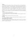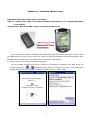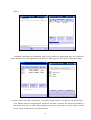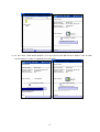
1
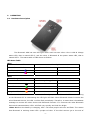
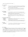
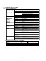
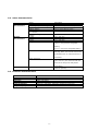
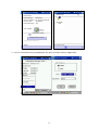
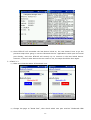
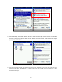
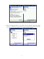
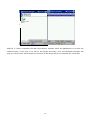
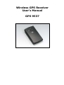
Wireless GPS Receiver User’s Manual GPS 9537 CONTENTS 1. Introduction ………………………………………. 1.1 Overview ………………………………………. 2 1.2 Main features ………………………………………. 2 2. Operation ………………………………………. 2.1 Hardware description - LED State Table ………………………………………. 3 2.2 Turning On/Off ………………………………………. 4 2.3 Charging ………………………………………. 4 2.4 Bluetooth Communication ………………………………………. 4 2.5 GPS Navigating feature ………………………………………. 4 2.6 PIN Code ………………………………………. 4 3. Technical Specifications ………………………………………. 3.1 Electrical Characteristics ………………………………………. 5 ………………………………………. 5 3.2 Other Characteristics ………………………………………. 6 3.3 Firmware Characteristics ………………………………………. 6 4. Notices ………………………………………. 7 5. Software Installation ………………………………………. 9 Operational Current & Power Consumption -1- 1. INTRODUCTION 1.1. Overview The GPS 9537 Wireless GPS receiver is a Global Positioning System Receiver with Bluetooth wireless technology. This wireless GPS receiver allows you to receive GPS data on mobile handheld wirelessly. By sending GPS position data over Bluetooth, you can position the receiver for the best possible reception all without wires. The advent of wireless GPS receiver will become the next level of GPS receivers. The GPS 9537 Wireless GPS receiver integrates Bluetooth module into GPS device. It shows the high performance, low power consumption, easily portable, rechargeable & removable battery function and wireless data transmission. If you have a Pocket PC or other portable devices enabled with Bluetooth function, for example iPAQ 3870/3970 and SONY Ericsson T68 mobile phone, you can take advantage of your device’s Bluetooth capability to wirelessly add GPS positioning technology. When you choose suitable navigation software, you can apply to personal, vehicle tracking, and marine navigation. If you use this wireless GPS receiver, you will ignore the messy cords and antenna and add the portability of your Pocket PC. In addition, This wireless GPS receiver can change the exhausted battery to full battery like battery of mobile phone. 1.2. Main Features 12 Channels “All-In-View” Tracking Position accuracy of 10 meters 2D RMS Cold/Warm/Hot Start Time: 45/38/8 Seconds Reacquisition Time: 0.1 seconds RF connector for external GPS antenna Support Standard NMEA-0183 Support Trickle Power mode Power Saving Compatible with Bluetooth devices with Serial Port Profile (SPP) Superior Sensitivity for Urban Canyon and Foliage Environment Small, sleek, and lightweight design easily fits in your hand Two LEDs indicating Bluetooth and GPS activity. Lithium-ion battery lasting full working day typical use On/off push button Dimension: 1.77” x 3.27” x 0.71” ( 45mm x 83mm x 18mm ) -2- 2. OPERATION 2.1. Hardware Description The Bluetooth GPS has two LED light which each has two colors. One is GPS & Charge status LED, that is named LED 2, and the other is Bluetooth & low power status LED, that is named LED 1. The status table of LED shows as follows: LED State Table LED1 BT & Low Power LED LED1 Color and Action Description Bluetooth Active Low Power Blue Flash Yes No Purple–Red Flash Yes Yes LED2 GPS & Charge LED LED2 Color and Action Description Battery Charged Position Fixed Dark No No Green Flash No Yes Red Yes No Orange-Red Flash Yes Yes <Note1>When the Bluetooth is active and LED 1 lights, it shows Bluetooth RF function. As long as the Bluetooth RF is transmitting the LED light will flash. When Bluetooth doesn’t connect the other Bluetooth device, the LED 1 will be flash periodically. Therefore, it means that it broadcasts message to connect the other device with Bluetooth function. If it connects the other Bluetooth device and transmits data, LED 1 will flash very quickly and look like bright. <Note 2>When the battery is charging, LED 1 will show purple-red color and flash. The reason that Bluetooth is working cause LED 1 purple-red color. If the GPS receiver go to the end of -3- charge, LED 1 will show blue color and flash. 2.2. Turn on/off Turn on To turn on the receiver, press the power button on the topside briefly (0.5 seconds). The left LED(LED 2) indicator will flash briefly. The right LED (LED 1) indicator will start flashing. Turn off To turn off the receiver, press the power button on the topside for 3 seconds. The LED indicator will flash briefly before switching off the receiver. 2.3. Charging Low Power The right LED(LED 1) indicator will turn RED (normally BLUE) when battery power becomes low. Connect the receiver to a powers source to continue operation and to recharge the battery. Charging The left LED(LED 2) indicator will turn RED (or ORANGE) when the battery is being charged. When fully charged, the RED indicator will switch off. 2.4. Bluetooth Communication Waiting to The right LED(LED 1) indicator will flash if there is no communication connect between the receiver and another device. Connected The right LED(LED 1) indicator will turn to continuous lighting when the receiver is connected through the wireless link with another device. 2.5. GPS Navigating The left LED(LED 2) will flash GREEN (or ORANGE when charging) if the receiver is able to determine the current position. 2.6. PIN CODE The PIN code means Personal Identification Number for Bluetooth device and it is also called as Pass Key. The Bluetooth GPS receiver has the default PIN Code, and is “0000”. Generally speaking, there are two steps in Bluetooth connecting. One is pairing process, the other is link process. If you need PIN code to pairing and connect, you can use the default pin code, “0000” to connect Bluetooth device. Our GPS receiver belongs to non-safety connecting, you can use in general application to finish connecting. -4- 3. TECHNICAL SPECIFICATIONS 3.1. Electrical Characteristics Chipset General Accuracy Datum Acquisition Rate(Open Sky & Stationary Requirements) Acquisition Sensitivity Dynamic Conditions Power Interface Items GSP2e/LP Frequency C/A code Channels Position Description SiRF starII LP technology L1, 1575.42 MHz 1.023 MHz chip rate 12 10 meters, 2D RMS 7 meters 2D RMS, WAAS corrected <5 meters(50%), DGPS corrected Velocity 0.1 meters/second Time 1 microsecond synchronized to GPS time Default WGS-84 Other selectable for other Datum Reacquisition 0.1 sec., average Snap start 2 sec., average Hot start 8 sec., average typical TTFF Warm start 38 sec., average typical TTFF Cold start 45 sec., average typical TTFF Hot 23 dB-Hz Warm 28 dB-Hz Cold 32 dB-Hz Tracking Sensitivity 16 dB-Hz <Note>32dB Hz is equivalent to -172 dBW Altitude 18,000 meters (60,000 feet) max. Velocity 515 meters/second (1000 knots) max. Acceleration 4g, max. Jerk 20 meters/second3, max. Operational Power 3.3VDC±10% (from internal Lithium-Ion battery pack) Input Power 5VDC±10% Battery Source Rechargeable and removable 900mAh Lithium-Ion battery with 5V DC input charging circuit. Battery Charging Full charge 3 hours Backup Power 3.3V ( internal on board rechargeable backup battery) Please refer to the following table Operational Current & Power Consumption Connection: Communication via Bluetooth Serial Port Profile(SPP) Protocol messages NMEA-0183 Version 2.20 output protocol Output message Default output format: GGA(1sec), GSA(5sec), GSV(5sec), RMC(1sec),VTG(1sec) Operational Current & Power Consumption Measure of Power Consumption Status Power On GPS connect BT LR-9537 Fix without connecting BT Device. LR-9537 Fix with connecting BT Device Current (mA) 75 70 20 100 -5- Power Consumption(mW) 300 280 80 400 3.2. Other Characteristics Environmental Characteristics Physical Characteristics Items Humidity range Operating temperature range Battery discharge Battery charge Short period storage temperature (< 1 month) Long time storage temperature(>1 month) Length Width Height Weight Description 5% to 95% No condensing -20ºC to +60ºC (-4ºF to 140ºF) -20ºC to +60ºC (-4ºF to 140ºF) 0ºC to +40ºC (32ºF to 104ºF) -20ºC to +50ºC (-4ºF to 112ºF) -20ºC to +35ºC (-4ºF to 95ºF) 3.27” (83 mm) 1.77” (45mm) 0.71” (18 mm) 1.82 oz / 52g (without chargeable battery) 2.73 oz / 78g (with chargeable battery) Antenna connector MC plug -Note: The internal antenna will be disables when an external antenna is connected. Power connector ψ2.1*5.5*9.5 ( The connector look the same as the DC jack of iPAQ 36/38 Antenna series PDA. ) Built-in Ceramic patch antenna (External antenna optional) Antenna type 3.3. Firmware Characteristics Items Core of firmware Baud rate Code type Datum Protocol message Output frequency Description SiRF version 2.3 4800 NMEA-0183 ASCII WGS-84 GGA(1sec), GSA(5sec), GSV(5sec), RMC(1sec),VTG(1sec) 1 Hz -6- 4. NOTICES 4.1. Global Positioning System The Global Positioning System (GPS) is operated and maintained by the Government of the United States of America who are responsible for the availability and the accuracy of the system. Changes in the operation, availability and accuracy may affect the operation of your GPS receiver. 4.2. Aircraft and Hospitals Use of devices with an antenna is prohibited on most aircraft and in many hospitals. The GPS 9537 Wireless GPS receiver is a receiving and transmitting device with two antenna’s and should not be used in these environments. 4.3. Heat Reflective Shields Modern vehicles may have a heat reflective shield in the windshield, preventing proper GPS signal reception if the receiver is placed under the windshield. To get proper reception: (a) Use an external antenna, or (b) Place the receiver in a different position, or (c) Attach the cradle to the windshield behind the rearview mirror, where many vehicles have an opening in the heat reflective shield, indicated by a black outline. 4.4Important The information in this document is subject to change without notice. No liability shall be assumed for technical or editorial errors or omissions contained herein; nor for incidental or consequential damages resulting from the performance or use of this material. This document contains information protected by copyright. 4.5 Battery This product uses a Lithium-Ion battery. Please charge fully before first use. Operation in low (below 0ºC/32ºF or high (over 40 C/110ºF) temperatures will affect power supply efficiency and the ability to charge the battery. All Lithium-Ion batteries will experience power supply efficiency deterioration over time even if not used and have a limited life expectancy. Permanently powering the battery will reduce life expectancy. Do not use your product in a humid, wet and/or corrosive environment. Do not put, store or leave your product in or near a heat source or in a high temperature location and do not expose it to temperature over 60ºC(140ºF). Failure to follow these guidelines may cause the Lithium-Ion battery to become hot, explode or ignite and cause injury and/or damage. THE LITHIUM-ION BATTERY CONTAINED IN THE PRODUCT MUST BE RECYCLED OR DISPOSED OF PROPERLY. USE ONLY WITH SUPPLIED CHARGER(s) AND SUPPLIED AC ADAPTOR FOR BATTERY CHARGING. -7- 4.6 FCC This equipment has been tested and found to comply with the limits for a Class B digital device, pursuant to Part 15 of the FCC Rules. These limits are designed to provide reasonable protection against harmful interference in a residential installation. This equipment generates, uses and can radiate radio frequency energy and, if not installed and used in accordance with the instructions, may cause harmful interference to radio communications. However, there is no guarantee that interference will not occur in a particular installation. If this equipment does cause harmful interference to radio or television reception, which can be determined by turning the equipment off and on, the user is encouraged to try to correct the interference by one or more of the following measures: --Reorient or relocate the receiving antenna. --Increase the separation between the equipment and receiver. --Connect the equipment into an outlet on a circuit different from that to which the receiver is connected. --Consult the dealer or an experienced radio/TV technician for help. CAUTION Any changes or modifications not expressly approved by the grantee of this device could void the user’s authority to operate the equipment. FCC RF Radiation Exposure Statement This equipment complies with FCC RF radiation exposure limits set forth for an uncontrolled environment. This equipment should be installed and operated with a minimum distance of 20cm between the radiator and your body. -8- APPENDIX A SOFTWARE INSTALLATION iPAQ Bluetooth Setup with Pocket PC software <Note 1> These steps apply to the PDA with Bluetooth function, for example iPAQ 3870 or 3970 PDA <Illustration> Bluetooth GPS receiver and iPAQ h3970 device There are several steps to use Bluetooth GPS(9537) with PDA (Bluetooth Built-in PDA or PDA with Bluetooth CF card) for user. Since the version of BTW-CE (Widcomm Bluetooth Manager) may be different for all PDA, there two operations introduced in the manual. 1. How to Check The Version of Bluetooth Manager It’s very simple to check the version of BTW-CE. If BTWCE is installed in the PDA, there will be a Bluetooth icon ( or ) displayed in the right of the bottom of screen. and the declaration for copyright of BTWCE will be shown in “about” page. Bluetooth Security Manager Version 1.1 Copyright © 2002 Compaq Computer Corporation -9- The information 2. BTWCE 1.1 Bluetooth (1) Make sure that the Bluetooth Device is powered on. (2) Select “Bluetooth Manager”. Start August 22 2003 Melvin Farewell No Appointments No Unread Mails No Unfinished Tasks Add About Wireless Bluetooth Manager Start ActiveSync Status About (3) When the Bluetooth Manager is executed, the user can check COM port configuration. Choose “Tool”, and then select “Setup all Device”. Then in “Serial Port” Page, the user will see Outbound COM Port which will be used by application. In this case, the com port is 8. All Devices Enable service Authorization required Authentication (Passkey) required Encryption required Inbound COM Port: Outbound COM Port: PIM Object General Serial Port Connect Link File Sharing (4) Select “Search” to find target device, then BTW-CE will start to search nearby Bluetooth -10- device. All Devices Add Device Name Blue… Stop Type Not def. Save Select Searching Device… View Tool Search Finishing searching and “Bluetooth GPS” found, select the target and save it for selected group. In this case, the target device is saved to default group. Then click to save the target. Add Device Name Blue.. Not def 13400-0866A Without-NAME Type Work. Work. Save Devices to the following Group All Devices Tasks Home Search Save Select Found 3 Devices Confirm Cancel Add Group (5) Back to the main form of BTW-CE, if there’re devices saved, the device list should seen. Then double-click the target device, BTW-CE will start to search the service provided by the target device for a while. After searching services, if the device is alive, there should be the name of SPP service on the action list. -11- All Devices Device Info Device Name Device Location Device Type Has Connection Bluetooth GPS Bluetooth 00:10:C6:1D:DC:A6 Undefined No Last Viewed ActiveSync Buddy Display Device Group Receiving Device Service… View Tool Search Action (6) In this case, “GPS Serial Output” is on the list for the SPP service. Select “Link to GPS Serial Output” to start to establish the serial link. Device Info Device Info Device Name Device Location Device Type Has Connection Bluetooth 00:10:C6:1D:DC:A6 Undefined No Last Viewed Device Name Device Location Device Type Has Connection 2003/8/22 Bluetooth 00:10:C6:1D:DC:A6 Undefined No Last Viewed ActiveSync Buddy ActiveSync Buddy Display Device Group Link to GPS Serial Output Setup Device Link Remove Device Establishing Serial Link… Action Action -12- All Devices Device Info Device Name Device Location Device Type Has Connection Bluetooth 00:10:C6:1D:DC:A6 Undefined No Bluetooth GPS Last Viewed ActiveSync Buddy Display Device Group Serial Link Established Action View Tool Search (7) As the connection being established, the port could be used by application. -13- (8) Since BTW-CE will remember the last device linked to, the user doesn’t have to go the previous steps when going to use the Bluetooth device. Applications could open the serial port directly, and then BTW-CE will smartly try to connect to the last linked device. However, if there’s other device the user want to use, the steps should be done again. 3. BTWCE 1.3 (1) Make sure that the status of Bluetooth is on. (2) Change the page to “Serial Port”, then check which com port used as “Outbound COM -14- Port”. In this case, the number of com port is 6. And then change to “about” page, there should be version string shown. (3) Click the “Bluetooth Manager” in “General” page. Select “New” and “Connect!” to add new device. (4) Then the Bluetooth Connection Wizard will be executed. Select “Explore a Bluetooth device” and click “Next”. Tab the Device frame on the form to start to search. -15- (5) After searching, the found devices will list. Click on the target to find service. If the SPP service is found, the service name will be shown in Device frame. Then select the target service and click “Next”. Bluetooth GPS Bluetooth GPS (6) After the previous steps, the wizard will show the message to tell the user that the link shortcut has been established. It means that the user could see the shortcut in the Bluetooth Manager. -16- Bluetooth GPS Bluetooth GPS: GPS S… (7) Select the target and hold on it for a while, then the sub-menu will pop-up. Select “Connect” to establish the link. If successes, the icon of target device will turn into green. As the connection has been established, application could open the port. Bluetooth GPS: GPS Connecting … -17- Bluetooth GPS: GPS S… BTW-CE 1.3 won’t remember the last linked device. Instead, when the application try to open the outbound port, if the port is not link to the target previously, then the Bluetooth Manager will pop-up. And the user would select the shortcut of the target device to complete the connection -18-