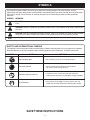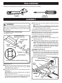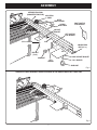
1
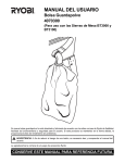
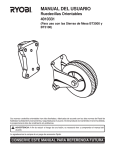
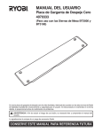
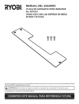
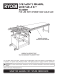
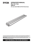
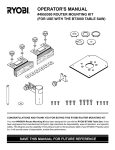
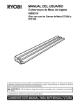
OPERATOR'S MANUAL LONG MITER/RIP FENCE KIT 4060300 FOR USE WITH RYOBI BT3000, BT3100 AND BT3100-1 TABLE SAWS THIS KIT MAKES EITHER A LONG MITER FENCE OR A LONG RIP FENCE FOR USE WITH BT3000, BT3100 AND BT3100-1 TABLE SAW LONG MITER FENCE LONG RIP FENCE TABLE SAW IS NOT INCLUDED WITH THIS KIT Your new Long Miter/Rip Fence kit has been engineered and manufactured to Ryobi's high standard for dependability, ease of operation, and operator safety. Properly cared for, it will give you years of rugged, trouble-free performance. WARNING: To reduce the risk of injury, the user must read and understand the operator's manual before using this product. Thank you for buying a Ryobi accessory kit. SAVE THIS MANUAL FOR FUTURE REFERENCE TABLE OF CONTENTS Introduction....................................................................................................................................................................... 2 Rules For Safe Operation ................................................................................................................................................. 2 Symbols............................................................................................................................................................................ 3 Unpacking......................................................................................................................................................................... 4 Loose Parts ...................................................................................................................................................................... 4 Tools Needed.................................................................................................................................................................... 5 Assembly .......................................................................................................................................................................5-8 Parts Ordering / Service ................................................................................................................................................. 10 INTRODUCTION This Long Miter/Rip Fence kit has many features for making the use of this product more pleasant and enjoyable. Safety, performance, and dependability have been given top priority in the design of this product making it easy to maintain and operate. WARNING: Do not attempt to use this product until you read thoroughly and understand completely the operator’s manual. Pay close attention to the safety rules, including Dangers, Warnings, and Cautions. If you use your product properly and only as intended, you will enjoy years of safe, reliable service. WARNING: The operation of any tool can result in foreign objects being thrown into your eyes, which can result in severe eye damage. Before beginning operation, always wear safety goggles or safety glasses with side shields and a full face shield when needed. We recommend Wide Vision Safety Mask for use over eyeglasses or standard safety glasses with side shields. Always wear eye protection which is marked to comply with ANSI Z87.1. Look for this symbol to point out important safety precautions. It means attention!!! Your safety is involved. RULES FOR SAFE OPERATION Safe operation of this accessory requires that you read and understand this operator's manual, the operator’s manual for the table saw and all labels affixed to the tool. BEFORE MAKING A CUT, BE SURE ALL ADJUSTMENTS ARE SECURE. SAVE THESE INSTRUCTIONS. Refer to them frequently and use them to instruct other users. If you loan someone this product, also loan these instructions. READ ALL INSTRUCTIONS KNOW YOUR ACCESSORY. Read the operator's manual carefully. Learn the product's applications and limitations as well as the specific potential hazards related to this product. KEEP THE WORK AREA CLEAN. Cluttered work areas and work benches invite accidents. DO NOT leave tools or pieces of wood on the saw while operating. ALWAYS WEAR SAFETY GLASSES WITH SIDE SHIELDS. Everyday eyeglasses have only impactresistant lenses; they are NOT safety glasses. DO NOT USE THIS PRODUCT WITH OTHER EQUIPMENT or for other purposes. ALWAYS DISCONNECT THE SAW FROM THE POWER SUPPLY BEFORE ASSEMBLING THIS KIT. Make sure the switch is off when reconnecting the saw to a power supply. WARNING: Some dust created by power sanding, sawing, grinding, drilling, and other construction activities contains chemicals known to cause cancer, birth defects or other reproductive harm. Some examples of these chemicals are: • lead from lead-based paints, • crystalline silica from bricks and cement and other masonry products, and • arsenic and chromium from chemically-treated lumber. Your risk from these exposures varies, depending on how often you do this type of work. To reduce your exposure to these chemicals: work in a well ventilated area, and work with approved safety equipment, such as those dust masks that are specially designed to filter out microscopic particles. 2 SYMBOLS The purpose of safety symbols is to attract your attention to possible dangers. The safety symbols, and the explanations with them, deserve your careful attention and understanding. The safety warnings do not by themselves eliminate any danger. The instructions or warnings they give are not substitutes for proper accident prevention measures. SYMBOL MEANING DANGER: Indicates an imminently hazardous situation, which, if not avoided, will result in death or serious injury. WARNING: Indicates a potentially hazardous situation, which, if not avoided, could result in death or serious injury. CAUTION: Indicates a potentially hazardous situation, which, if not avoided, may result in minor or moderate injury. It may also be used to alert against unsafe practices that may cause property damage. Note: Advises you of additional information concerning the operation or maintenance of the equipment. SAFETY AND INTERNATIONAL SYMBOLS This operator's manual describes safety and international symbols and pictographs that may appear on this product. Read the operator's manual for complete safety, assembly, operating and maintenance, and repair information. SYMBOL NAME MEANING Wet Condition Alert • Do not expose to rain or use in damp locations. No Hands Symbol • Failure to keep your hands away from the blade Read the Operator’s Manual • To reduce the risk of injury, the user must read and understand the operator’s manual before using this product. Eye Protection will result in serious personal injury. • Always wear safety goggles or safety glasses with side shields and a full face shield when operating this product. SAVE THESE INSTRUCTIONS 3 UNPACKING Your new long miter/rip fence kit includes a 41 in. extension rail, plus the necessary brackets, and connecting hardware required to assemble a long miter fence and attach it to the sliding miter table of your BT3000/BT3100/BT3100-1 table saw. It also includes connectors and hardware required for attaching a long rip fence to your saw. Remove the parts from the box. Make sure that all items listed in the loose parts list are included. Inspect all parts carefully to make sure no breakage or damage occured during shipping. If any parts are damaged or missing, please call 1-800525-2579 for assistance. Note: When used as a long miter fence this kit temporarily replaces the miter fence supplied with your saw. When used as a long rip fence it attaches to the rip fence supplied with your saw. WARNING: If any parts are missing do not assemble the kit until the missing parts are replaced. Failure to do so could result in serious personal injury SQUARE HEAD BOLT (1/2 in.) SAW GAGE HEX BOLT (1/2 in.) CONNECTOR LOCATOR PIN MITER/RIP FENCE RAIL T-NUT WORK SUPPORT BRACKET PLASTITE SCREW MITER INDICATOR SAW GAGE KNOB BOLT 5/16 in. WASHER HEX BOLT (7/8 in.) BRACKET (RIGHT POSITIVE STOP) 1/4 in. WASHER BRACKET (SUPPORT AND LEFT POSITIVE STOP) KNOB NUT Fig. 1 LOOSE PARTS Miter/Rip Fence Rail .........................................................1 Bracket (Support and Left Positive Stop)..........................2 Saw Gage.........................................................................2 Knob Bolt .........................................................................1 Knob Nut ..........................................................................1 T-Nut ................................................................................6 Square Head Bolt (1/2 in.) ................................................1 5/16 in. Washer.................................................................6 Bracket (Right Positive Stop) ............................................1 1/4 in. Washer...................................................................1 Plastite Screw...................................................................2 Work Support Bracket ......................................................1 Hex Bolt (7/8 in.)...............................................................1 Miter Indicator...................................................................1 Locator Pin .......................................................................1 Connector .........................................................................2 Hex Bolt (1/2 in.)...............................................................4 4 TOOLS NEEDED You need an adjustable wrench and phillips screwdriver to assemble this accessory. ADJUSTABLE WRENCH #2 PHILLIPS SCREWDRIVER ASSEMBLY Slide the locator pin into the bottom channel of the long miter fence rail. Note: The locator pin assembled to the miter fence provided with your BT3000/BT3100/BT3100-1 table saw is assembled identical to this assembly. This locator pin fits in either hole "A" or hole "B" when mounting the long miter fence to the sliding miter table. Note: Raised ribs on the locator pin create a tight fit when installing the locator pin. It may be necessary to force the locator pin into the holes at first. See Figure 2. WARNING: The table saw should never be connected to a power supply when you are assembling parts. Disconnecting the saw will prevent accidental starting that could cause serious personal injury. TO ASSEMBLE THE LOCATOR PIN See Figures 1 and 2. MITER/RIP FENCE RAIL (LONG MITER FENCE RAIL) ASSEMBLE THE MITER INDICATOR Align the miter indicator with the tapered groove on the long miter fence rail. Slide the miter indicator onto the rail. The bottom of the miter indicator should be next to the sliding miter table. Note: The miter indicator for the long miter fence is the same as the miter indicator on the miter fence provided with your BT3000/BT3100/BT3100-1 table saw. Use the miter indicator with the scale on the sliding miter table to set desired angles for making miter cuts MITER INDICATOR PLASTITE SCREW T-NUTS ASSEMBLE THE T-NUTS Slide two of the T-nuts into the bottom channel of the long miter fence rail. T-nuts will be used later to secure the brackets. The T-nuts must be placed in the channel before assembling the plastite screws. The plastite screws trap the T-nuts inside the channel. SAW GAGE TAPERED GROOVE ADJUSTING KNOB RAIL ORIENTATION FOR LONG MITER FENCE SETUPS Fig. 1 ATTACHMENT BOLT MITER FENCE HOLDER MITER FENCE Unplug the saw. Remove the miter fence, the miter fence holder, and the adjusting knob from sliding miter table on your BT3000 /BT3100/BT3100-1 table saw. Place the long miter fence rail on the sliding miter table. See Figure 2. IMPORTANT: Rail must be oriented exactly as shown for proper assembly of all parts. Drilled holes in the rail are in the bottom channel when using the rail as a long miter fence. Drilled holes are in the top channel when using the rail as a long rip fence. LOCATOR PIN HOLE "A" MITER INDICATOR HOLE "B" 5 TABLE SLOT Fig. 2 ASSEMBLY ASSEMBLE THE SAW GAGES SQUARE HEAD BOLT (1/2 in.) See Figure 3. Place a saw gage into each end of the long miter fence rail. Correct orientation of the saw gage to the rail is important. Align the slot in the saw gage with the slot in the rail. MITER/RIP FENCE RAIL (LONG MITER FENCE RAIL) 1/4 in. WASHER KNOB NUT Secure both saw gages to the rail with the plastite screws provided. The long miter fence rail has drilled holes on the bottom at each end. Place screws through these holes and thread into the pilot holes in the saw gages. MITER/RIP FENCE RAIL (LONG RIP FENCE RAIL) Note: If the screw holes in saw gages become stripped after extended use, turn them over and secure to the opposite ends of rail. Pilot holes have been provided on both the top and bottom of saw gages. Tighten screws securely. RIGHT POSITIVE STOP BRACKET MITER INDICATOR LOCATOR PIN SQUARE HEAD BOLT (1/2 in.) ASSEMBLE THE MITER FENCE HOLDER AND THE ADJUSTING KNOB PLASTITE SCREW 1/4 in. WASHER See Figure 4. Reassemble the miter fence holder and the adjusting knob. Place the miter fence holder supplied with your BT3000/ BT3100/BT3100-1 table saw on the long miter fence and secure to the sliding miter table. T-NUTS 5/16 in. WASHER ASSEMBLE THE SUPPORT BRACKET KNOB NUT See Figures 3 and 4. The support bracket attaches to the bottom of long miter fence and sliding miter table. As the name implies it provides support and stability for the long miter fence rail. SUPPORT BRACKET LEFT POSITIVE STOP BRACKET Orient the support bracket as shown in figure 5. Slide the bracket under the edge of the sliding miter table. Secure the support bracket to the bottom of the long miter fence with a 5/16 in. washer and hex bolt (7/8 in). HEX BOLT (7/8 in.) WORK SUPPORT BRACKET SAW GAGE SLOT 5/16 in. WASHER KNOB BOLT Fig. 3 ASSEMBLE THE WORK SUPPORT BRACKET Note: Thread the hex bolt (7/8 in) into a T-nut closest to the table saw. See Figures 3 and 4. The work support bracket attaches to the bottom of long miter fence. As the name implies it provides support and stability for long workpieces when making miter cuts on long stock. Tighten the bolt securely. ASSEMBLE THE POSITIVE STOP BRACKET See Figures 3 and 4. Attach work support bracket to bottom of long miter fence as shown in figures 3 and 4. Two positive stop brackets have been provided for use as gages when making repetitive cuts. One each is provided for left or right side application. Secure the bracket with a 5/16 in. washer and the knob bolt. Thread the knob bolt into the remaining T-nut in the bottom channel or the rail. Insert the square head bolt (1/2 in) in the slot in the rip fence. Tighten the knob bolt securely. Attach the positive stop bracket to the long miter fence and secure with a 1/4 in. washer and the knob nut. COMPLETED LONG MITER FENCE ASSEMBLY Place either of the left or right positive stop brackets at the desired position on the rail for repetitive cuts, etc. After assembling all the parts, your long miter fence should be similar to the illustration shown in figure 5. Recheck all necessary steps. Recheck all bolts, screws, and knobs for tightness. See Figure 5. Tighten the knob nut securely. 6 ASSEMBLY MITER/RIP FENCE RAIL (LONG MITER FENCE RAIL) ADJUSTING KNOB MITER FENCE HOLDER SLIDING MITER TABLE RIGHT POSITIVE STOP BRACKET SUPPORT BRACKET LEFT POSITIVE STOP BRACKET SLOT 5/16 in. WASHER SQUARE HEAD BOLT (1/2 in.) HEX BOLT (7/8 in.) KNOB NUT WORK SUPPORT BRACKET 1/4 in. WASHER 5/16 in. WASHER KNOB BOLT Fig. 4 LONG MITER FENCE ASSEMBLY SHOWN ATTACHED TO A BT3000/BT3100/BT3100-1 TABLE SAW Fig. 5 7 ASSEMBLY This kit also includes connectors and hardware required for attaching a long rip fence to your saw. If you have been using this kit as a long miter fence, it will be necessary to remove all connectors, brackets, hardware, etc. If you are assembling for the first time, proceed as follows. HEX BOLT (1/2 in.) ASSEMBLE THE LONG RIP FENCE CONNECTOR 5/16 in. WASHER See Figures 6, 7, and 8. T-NUT LONG RIP FENCE The long rip fence rail attaches to the existing rip fence on your table saw, to provide a long extension rail when ripping large panels and long pieces of work. Place the long rip fence rail on the saw table. IMPORTANT: Rail must be oriented exactly as shown for proper assembly of all parts. Drilled holes in the rail are on the top channel when using as a long rip fence. They are in the bottom channel when using the rail as a long miter fence. RIP FENCE Slide two of the special T-nuts into the top channel of the long rip fence rail. T-nuts will be used to secure the connectors. The T-nuts must be placed in the channel before assembling the plastite screws. Plastite screws trap the T-nuts inside the channel. Fig. 7 Attach the long rip fence to the existing rip fence on the saw with two connectors. Secure the connectors using 5/16 in. washers and hex bolts (1/2 in.). RAIL ORIENTATION FOR LONG RIP FENCE SETUPS Tighten bolts securely. COMPLETED LONG RIP FENCE ASSEMBLY PLASTITE SCREW See Figure 8. After assembling all the parts, your long rip fence should be similar to the illustration shown in figure 9. Recheck all necessary steps. Recheck all bolts and screws for tightness. LONG RIP FENCE ASSEMBLY SHOWN ATTACHED TO A RYOBI TABLE SAW T-NUTS MITER/RIP FENCE RAIL (LONG RIP FENCE RAIL) SAW GAGE Fig. 6 Place a saw gage into each end of long miter fence rail. Correct orientation of saw gage to rail is important. Align the slot in the saw gage with the slot in the rail. Secure each saw gage to the rail with plastite screws provided. The long rip fence rail has holes drilled on the top at each end. Place screws through these holes and thread into the pilot holes in the saw gage. Note: If the screw holes in the saw gages become stripped after extended use, turn the saw gages over and secure to the opposite ends of the rail. Pilot holes have been drilled on both the top and bottom of the saw gages. Fig. 8 Tighten the screws securely. Slide two of the T-nuts into the top channel of your saw's rip fence. T-nuts will be used to secure the connectors. The T-nuts must be placed in the channel from the rear of the saw. See Figure 7. 8 RYOBI LONG MITER/RIP FENCE KIT NO. 4060300 Now that you have purchased your Long Miter/Rip Fence Kit, should a need ever exist for repair parts or service, simply contact your nearest Ryobi Authorized Service Center. Be sure to provide all pertinent facts when you call or visit. 4 7 6 8 5 3 9 2 10 11 4 1 15 14 17 Key No. 1 2 3 4 5 6 7 8 9 10 11 12 13 14 15 16 17 Part Number 661815-001 969959-002 969958-001 969190-001 661811-001 * 623166-005 * 616670-014 970147-002 969251-001 968702-009 969191-002 * 706382-358 661816-001 * 615570-014 * 706382-361 969960-002 662125-001 972000-218 12 16 13 PARTS LIST Description Qty. Knob Bolt (5/16-18 x 1/2 in.) ..........................................................................1 Bracket (Work Support) .................................................................................1 Miter/Rip Fence Rail ......................................................................................1 Saw Gage ......................................................................................................2 Locator Pin.....................................................................................................1 Bolt (1/4-20 x 1/2 in. Sq. Hd.).........................................................................1 Bolt (5/16-18 x 1/2 in. Hex Hd.)......................................................................4 Connector ......................................................................................................2 5/16 in. T-Nut (Special)...................................................................................6 Screw (8-16 x 5/8 in. Plastite Pan Hd.) ..........................................................2 Miter Indicator ................................................................................................1 Washer (1/4 in.) .............................................................................................1 Knob Nut (1/4-20) ..........................................................................................1 Bolt (5/16-18 x 7/8 in. Hex Hd.)......................................................................1 Washer (5/16 in.) ...........................................................................................6 Bracket (Support and Left Positive Stop) ......................................................2 Bracket (Right Positive Stop) .........................................................................1 Operator's Manual * STANDARD HARDWARE ITEM — MAY BE PURCHASED LOCALLY 9 OPERATOR'S MANUAL LONG MITER/RIP FENCE KIT 4060300 FOR USE WITH RYOBI BT3000, BT3100 AND BT3100-1 TABLE SAWS • SERVICE Now that you have purchased your tool, should a need ever exist for repair parts or service, simply contact your nearest Ryobi Authorized Service Center. Be sure to provide all pertinent facts when you call or visit. Please call 1-800-525-2579 for your nearest Ryobi Authorized Service Center. You can also check our web site at www.ryobitools.com for a complete list of Authorized Service Centers. • HOW TO ORDER REPAIR PARTS WHEN ORDERING REPAIR PARTS, ALWAYS GIVE THE FOLLOWING INFORMATION: • MODEL NUMBER • SERIAL NUMBER 4060300 RYOBI TECHNOLOGIES, INC. 1428 Pearman Dairy Road Anderson, SC 29625 Post Office Box 1207, Anderson, SC 29622-1207 Phone 1-800-525-2579 www.ryobitools.com 972000-218 10-03 10