1
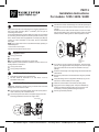
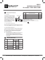
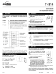
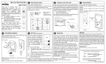
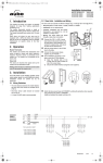
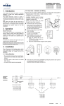
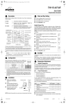
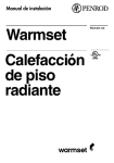
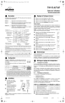
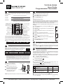
TH115-B-120GA
User Guide
Programmable Thermostat
1.
4.
Description
Clock and Day Setting
Aube’s TH115 programmable thermostats have three temperature
control modes:
Press the Hour button to set the hour.
A mode:
controls the ambient air temperature
Set the Day button to set the day.
F mode:
controls the floor temperature using an
external temperature sensor
AF mode:
controls the ambient air temperature
maintains the floor temperature within desired
limits using an external temperature sensor
On/Standby switch 1
and GFCI reset 2
Time and day display
Appears when the
setpoint is displayed
Temperature display
Set the Min button to set the minutes.
Press Mode/Ret to exit.
Daylight Savings Time
The thermostat can automatically re-adjust its clock at Daylight Savings Time changeover. When this function is enabled (On), the thermostat switches to Daylight Savings Time on the second Sunday of
March and to normal time on the first Sunday of November.
NOTE: The function is disabled (default setting) when the clock loses
its setting.
Press the Day button (3 seconds) until DLS appears
on the screen.
Mode display
Day and time
settings
Preset temperature
indicator
Percentage of
heating time 3
Press the
(disabled).
Ground fault indicator 4
Temperature control
mode indicator
Program button
Program
clear button
Press the Day button briefly. The year setting is displayed.
Press the
to set the current year.
Temperature
preset buttons
Mode selection /
program exit
Press the Day button briefly. The month setting is displayed.
Press the
to set the current month.
Period display
Temperature
adjustment buttons
Backlight button
to toggle between On (enabled) and Off
1
Place the switch in Standby to cut power to the heater when not in use (e.g., in the summer). This will not affect the time and temperature settings.
2
If your thermostat is installed on a power base equipped with a ground fault protection,
to reset the ground fault protection, switch the thermostat to Standby and back to On.
Press the Day button briefly. The date setting is displayed.
Press the
3
The thermostat displays the percentage of heating time required to maintain the desired
temperature. For example,
is displayed when heating is activated 40 percent of the
time.
to set the current date.
Press Mode/Ret to exit.
5.
Backlight
Display
% of heating time
4
1 to 24% 25 to 49% 50 to 74% 75 to 99%
100%
GFI appears when the ground fault protection has tripped.
2.
Configuration
Some thermostat configurations can be modified via
switches on the back of the faceplate (control module).
Default (factory) settings are inside the gray cells.
a.
b.
6.
Temperature Adjustment
6.1
#
Configurations
UP
DN
1
Display format
°F / 12 h
°C / 24 h
2
Early Start a
Enable
Disable
3
Temperature control mode b
F
AF
6.2
Comfort temperature
Economy temperature
3.
Air vents
Vacation temperature
To use a preset temperature, press the corresponding button. The
corresponding icon , or will be displayed.
The following table shows the intended use and the default setting of
each of the preset temperatures.
Icon
Insert the tabs at the top of
the control module in the slots
at the top of the power base.
Secure the control module
using the captive screw
underneath the base.
Preset Temperatures
The thermostat has 3 preset temperatures:
Installation
Control module
Setpoint Temperature
The thermostat normally displays the actual (measured) temperature.
To view the setpoint, press one of the
buttons once. The setpoint
will appear for the next 5 seconds.
To change the setpoint, press one of the
buttons until the desired
temperature is displayed. To scroll faster, press and hold the button.
Early Start can be used in Automatic mode only. When this function is enabled, the
thermostat calculates the optimal time to start heating in order to obtain the desired
temperature by the set time. The thermostat re-assesses the start time daily based
on the previous day’s results.
To select the F mode, place the switch in the F position. To select the AF mode,
place the switch in the AF position and ensure that the remote temperature sensor
is connected to the thermostat. To select the A mode, place the switch in the AF
position and ensure that the remote temperature sensor is NOT connected to the
thermostat.
Refer to the installation
instructions of the power
base.
The display illuminates for 12 seconds when the backlight button is
pressed.
When either of the
buttons is pressed, the display also illuminates
for 12 seconds. The setpoint temperature appears for 5 seconds,
then the actual (measured) temperature is displayed.
Air vents
Power base
NOTE: Keep the thermostat's air vents clean and unobstructed at all times.
A/AF modes
F mode
Comfort
(when at home)
Intended use
21 °C (70 °F)
28 °C (82 °F)
Economy
(when asleep or away from home)
17 °C (63 °F)
20 °C (68 °F)
Vacation
(during prolonged absence)
10 °C (50 °F)
10 °C (50 °F)
To store a preset temperature:
Set the desired temperature using the
buttons.
Press and hold the corresponding button until the corresponding
icon is displayed.
10170-B
3/09
24/7 Installation Support • Lifetime Technical Assistance • Free Design Service • www.WarmlyYours.com • (800) 875-5285
6.3
Floor Temperature Limits (AF mode only)
7.3
NOTE: To avoid damaging your floor, follow your floor supplier’s recommendations regarding floor temperature limits.
The minimum and maximum floor temperature limits are 5 °C (41 °F) and
28 °C (82 °F) by default. To modify these limits, proceed as follows:
button.
Switch the thermostat back to On.
Release the
button when the minimum temperature
) appears.
limit (
Set the minimum temperature limit using the
Press the
).
limit (
buttons.
button to display the maximum temperature
Set the maximum temperature limit using the
By pressing the
button on the thermostat. When the Vacation
mode is activated using the button, the icon appears on the
screen without flashing.
From an Aube telephone controller (CT240/CT241) or any other
remote control device equipped with a dry contact if your power
base is equipped with the ECONO input. When the contact
closes, the Vacation mode is activated and the icon flashes on
the screen. All buttons on the thermostat are locked. When the
contact opens, the thermostat returns to the preceding mode.
Switch the thermostat to Standby.
Press and hold the
Vacation Mode
In this mode, the thermostat is set to Vacation temperature. There
are two ways to place the thermostat in Vacation mode:
NOTE: When the Vacation mode is activated using a remote
control device, it can only be deactivated using the device.
buttons.
Press Mode/Ret to exit.
8.
Error Messages
7.
Modes of Operation
The measured temperature is below the thermostat’s display
range. Heating is activated.
The thermostat has 3 modes of operation.
7.1
Automatic Mode
The thermostat follows the programmed schedule. To place the thermostat in this mode, press Mode/Ret until is displayed. The data of
the current schedule period are also displayed.
Temporary Bypass
Verify the thermostat and sensor connections.
:
9.
If you modify the setpoint temperature (by pressing the
,
or
button) when the thermostat is in automatic mode, the new temperature will be used until the beginning of the next period. flashes during the bypass. You can cancel the bypass by pressing Mode/Ret.
Programmed Schedule
The schedule consists of 4 periods per day which represents a typical week day. You can program the thermostat to skip the periods
that do not apply to your situation. For example, you can skip periods
2 and 3 for the weekend.
Period
The measured temperature is above the thermostat’s display
range. Heating is deactivated.
Description
Associated temperature setting
Wake-up
Technical Specifications
Power supply: Refer to the power base’s installation guide.
Display range: 0 °C to 70 °C (32 °F to 158 °F)
Ambient setpoint range (A/AF modes): 5 °C to 30 °C (40 °F - 86 °F)
Floor setpoint range (F mode): 5 °C to 40 °C (40 °F - 104 °F)
Floor limit range (AF mode): 5 °C to 40 °C (40 °F - 104 °F)
Display resolution: 0.5 °C (1 °F)
Operating temperature: 0 °C to 50 °C (32 °F to 120 °F)
Storage temperature: -20 °C to 50 °C (-4 °F to 120 °F)
Heating cycle length: Refer to the power base’s installation guide
Data backup: In the event of a power failure, most settings are saved.
Only the time must be re-adjusted if the power failure lasts more than 6
hours. The thermostat will return to the mode that was active prior to the
power failure.
Away from home
10.
Warranty
Return home
Sleep
The Comfort (
) temperature is used in periods 1 and 3 and the
Economy ( ) temperature is used in periods 2 and 4. For example,
when the period changes from 1 to 2, the setpoint automatically
changes from Comfort ( ) temperature to Economy ( ) temperature.
You can have a different program for each day of the week; i.e., each
period can start at different time for each day of the week. The
thermostat has been programmed with the following schedule.
Period
Setting
MO
TU
WE
TH
FR
SA
SU
6:00
6:00
6:00
6:00
6:00
6:00
6:00
8:30
8:30
8:30
8:30
8:30
--:--
--:--
17:00
17:00
17:00
17:00
17:00
--:--
--:--
23:00
23:00
23:00
23:00
23:00
23:00
23:00
To modify the schedule:
Press Pgm to access the programming mode. Period 1 is
selected.
Press Day to select the day to program (hold for 3 seconds to
select the entire week).
Press Hour and Min to set the start time of the selected period,
or press Clear if you want to skip the period (--:-- is displayed).
NOTE: If you intend to use only 2 periods, set periods “1 and 4”
or periods “2 and 3”. Early Start will not work if you set periods
“1 and 2” or periods “3 and 4” .
Press Pgm to select another period, or press Day to select
another day. Then repeat step 3.
Press Mode/Ret to exit the programming mode.
NOTE: If no button is pressed for 60 seconds, the thermostat will
automatically exit the programming mode.
7.2
Manual Mode
The programmed schedule is not used. The temperature must be set
manually. To place the thermostat in this mode:
Press Mode/Ret until
is displayed.
Set the temperature using the
,
or
button.
Aube warrants this product, excluding battery, to be free from defects in the workmanship or materials, under normal use and service, for a period of three (3) years
from the date of purchase by the consumer. If at any time during the warranty
period the product is determined to be defective or malfunctions, Aube shall repair
or replace it (at Aube's option).
If the product is defective,
(i)
return it, with a bill of sale or other dated proof of purchase, to the place from
which you purchased it, or
(ii)
contact Aube. Aube will make the determination whether the product should
be returned, or whether a replacement product can be sent to you.
This warranty does not cover removal or reinstallation costs. This warranty shall
not apply if it is shown by Aube that the defect or malfunction was caused by damage which occurred while the product was in the possession of a consumer.
Aube's sole responsibility shall be to repair or replace the product within the terms
stated above. AUBE SHALL NOT BE LIABLE FOR ANY LOSS OR DAMAGE OF
ANY KIND, INCLUDING ANY INCIDENTAL OR CONSEQUENTIAL DAMAGES
RESULTING, DIRECTLY OR INDIRECTLY, FROM ANY BREACH OF ANY WARRANTY, EXPRESS OR IMPLIED, OR ANY OTHER FAILURE OF THIS PRODUCT. Some provinces, states or regions do not allow the exclusion or limitation of
incidental or consequential damages, so this limitation may not apply to you.
THIS WARRANTY IS THE ONLY EXPRESS WARRANTY AUBE MAKES ON THIS
PRODUCT. THE DURATION OF ANY IMPLIED WARRANTIES, INCLUDING THE
WARRANTIES OF MERCHANTABILITY AND FITNESS FOR A PARTICULAR
PURPOSE, IS HEREBY LIMITED TO THE THREE-YEAR DURATION OF THIS
WARRANTY. Some provinces, states or regions do not allow limitations on how
long an implied warranty lasts, so the above limitation may not apply to you.
This warranty gives you specific legal rights, and you may have other rights which
vary from province, state or region to another.
11.
Customer Assistance
For any questions regarding product installation or operation, contact us
at:
705 Montrichard
Saint-Jean-sur-Richelieu, Quebec
J2X 5K8
Canada
Tel.: (450) 358-4600
Toll-free: 1-800-831-AUBE
Fax: (450) 358-4650
E-mail: [email protected]
For more information on our products, visit us at:
www.aubetech.com
24/7 Installation Support • Lifetime Technical Assistance • Free Design Service • www.WarmlyYours.com • (800) 875-5285
PB112
Installation Instructions
For models: 120S / 240S / 240D
1.
Applications
This power base has been designed for floor heating applications. It
has ground fault protection (GFCI1 or EGFPD2) and an input for
connecting a floor sensor.
If your thermostat has the Vacation Mode, the mode can be activated
by connecting an Aube telephone controller (CT240 or CT241) or any
other remote control device equipped with a normally open (NO) dry
contact. For more information on this mode, see the thermostat’s
user guide.
NOTE: This power base must be used with thermostat operating on
15-minute cycles.
1
Ground Fault Circuit Interrupter
2
Equipment Ground Fault Protection Device
Insert the floor sensor cable through one of the two openings on
the base and connect the sensor wires to terminals 1 and 2 (no
polarity).
Position the sensor cable such that it does not come in contact
with the floor heating wires. The sensor probe must be centered
between two floor heating wires for best temperature control.
2.
Supplied Parts
One (1) power base
Two (2) screws
Four (4) solderless connectors for copper wires
NOTE: Special CO/ALR solderless connectors must be used for connecting aluminum conductors.
One (1) floor sensor
One (1) flat-tip screwdriver
3.
Installation Guidelines
Install the thermostat onto an electrical box.
Do NOT install the thermostat in an area where it can be
exposed to water or rain.
Floor
temperature
sensor
If you wish to connect a remote control device, insert the wires
(use 18- to 22-gauge flexible wires) through one of the two openings on the base and connect them to terminals 2 and 3 (no
polarity).
Push the excess length of the high-voltage wires back inside the
electrical box.
Secure the power base to the electrical box using the provided
screws.
Verify the settings of the configuration switches (if any) on the
back of the control module (see user guide).
4.
Install the control module on the base (see user guide).
Installation Procedure
Installation should be carried out by an electrician and must
comply with local electrical codes.
Turn off power to the heating system at the main power panel in
order to avoid any risk of electrical shock.
Connect the power base wires to the power supply and to the
load using solderless connectors for copper wires.
Apply power to the heating system. Verify the installation by
making sure that the heating system can be turned on and
turned off by increasing and decreasing the setpoint.
Test the ground fault protection.
Power supply
Load
24/7 Installation Support • Lifetime Technical Assistance • Free Design Service • www.WarmlyYours.com • (800) 875-5285
PB112
Installation Instructions
For models: 120S / 240S / 240D
Ground Fault Protection
Model
5.1 Description
The power base protects against risks
of electrocution caused by leakage
current. If the leakage current exceeds
5 mA or 15 mA (depending on the
model), the ground fault protection will
automatically trigger, cutting power to
the floor heating system. To indicate
the fault, the TEST light on the top of
the base will illuminate (red).
TEST button/light
Ground Fault Protection
Leakage
Current
120GA Ground Fault Circuit Interrupter (GFCI)
5 mA
120GB Equipment Ground Fault Protection Device (EGFPD)
15 mA
240GA Ground Fault Circuit Interrupter (GFCI)
5 mA
240GB Equipment Ground Fault Protection Device (EGFPD)
15 mA
Heating cycle length: 15 minutes
Storage: -20 °C to 50 °C (-4 °F to 120 °F)
Size (H • W • D): 124 x 70 x 23 mm (4.89 x 2.76 x 0.91 in.)
Certifications:
5.2 Ground Fault Protection Reset
When the ground fault protection has triggered, reset it by switching
the thermostat to Standby and back to On. The TEST light will go off.
5.3 Ground Fault Protection Test
To ensure the ground fault protection is always in working order, test
it once the thermostat is installed and on a monthly basis thereafter.
Increase the setpoint temperature above the measured floor
temperature in order to activate the floor heating system.
Press the TEST button.
• The test is successful if the TEST light is On (red). Reset the
thermostat and place it back to the desired temperature.
• The test has failed if the TEST light remains off. Cut power to
the heating system at the main electrical panel and replace
the thermostat.
6.
Technical Specifications
Maximum Load
Model
Supply
Wiring
Current
Power
120GA
120 VAC, 50/60Hz
15 A
1800 W
4 wires
double pole
120GB
120 VAC, 50/60Hz
15 A
1800 W
4 wires
double pole
240GA
240GB
240 VAC, 50/60Hz
208 VAC, 50/60Hz
240 VAC, 50/60Hz
208 VAC, 50/60Hz
15 A
15 A
3600 W
3120 W
3600 W
3120 W
4 wires
double pole
4 wires
double pole
24/7 Installation Support • Lifetime Technical Assistance • Free Design Service • www.WarmlyYours.com • (800) 875-5285