1
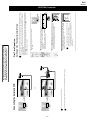
WA1
RM-Y1108
WA1 CHASSIS
SERVICE MANUAL
MODEL
KLV-20SR3
COMMANDER
RM-Y1108
DEST
MODEL
COMMANDER
DEST
AEP
KLV-20SR3
RM-Y1108
FLAT PANEL COLOR TV
-1-
WA1
RM-Y1108
TABLE OF CONTENTS
Section
Title
Page
Caution ................................................................
Specifications ......................................................
Connectors ..........................................................
Self Diagnosis .....................................................
3
4
5
6
1. GENERAL ...................................................................
7
2. DISASSEMBLY
2-1. Rear Cabinet Assembly Removal .......................
2-2. Stand Removal ....................................................
2-3. Rear Cover Removal ...........................................
2-4. Speaker Removal ................................................
2-5. A Board Removal ...............................................
2-6. G Board Removal ...............................................
2-7. H1 Board Removal .............................................
2-8. H2 Board Removal .............................................
2-9. H3 Board Removal .............................................
2-10. H5 Board Removal .............................................
2-11. LCD Bracket Removal ........................................
2-12. LCD Removal .....................................................
18
18
19
19
20
20
21
21
22
22
23
23
3. SET-UP ADJUSTMENTS
3-1. Signal Adjustment .............................................
3-1-1. Pal auto adjustment (CVBS) ...........................
3-1-2. Pal auto adjustment (RGB) ..............................
3-2. White Balance Adjustment .................................
3-2-1. White Balance adjustment (H/L) .....................
3-2-2. White Balance adjustment (C/O) .....................
24
24
24
24
24
24
Section
4. DIAGRAMS
4-1. Block Diagrams (1) ............................................
Block Diagrams (2) ............................................
4-2. Circuit Board Location ........................................
4-3. Schematic Diagrams and Printed Wiring
Boards .................................................................
A Board Schematic Diagram ..............................
A Printed Wiring Board ....................................
G Board Schematic Diagram ..............................
G Printed Wiring Board ....................................
H1 Board Schematic Diagram ............................
H1 Printed Wiring Board ..................................
H2 Board Schematic Diagram ............................
H2 Printed Wiring Board ..................................
H3 Schematic Diagram .......................................
H3 Printed Wiring Board ..................................
H5 Schematic Diagram .......................................
H5 Printed Wiring Board ..................................
4-4. Semiconductors ..................................................
Page
25
26
26
26
27
30
32
33
34
35
34
35
36
37
36
37
38
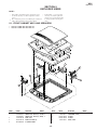
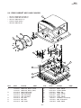
5. EXPLODED VIEWS
5-1. Front Cabinet Assy and Speakers ......................
5-2. Rear Cabinet Assy and Chassis ..........................
40
41
6. ELECTRICAL PARTS LIST ..................................
42
WARNING !!
AN ISOLATION TRANSFORMER SHOULD BE USED DURING
ANY SERVICE WORK TO AVOID POSSIBLE SHOCK HAZARD
DUE TO LIVE CHASSIS, THE CHASSIS OF THIS RECEIVER IS
DIRECTLY CONNECTED TO THE POWER LINE.
Title
SAFETY-RELATED COMPONENT WARNING !!
COMPONENTS IDENTIFIED BY SHADING AND MARKED ON
THE SCHEMATIC DIAGRAMS, EXPLODED VIEWS AND IN THE
PARTS LIST ARE CRITICAL FOR SAFE OPERATION. REPLACE
THESE COMPONENTS WITH SONY PARTS WHOSE PART
NUMBERS APPEAR AS SHOWN IN THIS MANUAL OR IN
SUPPLEMENTS PUBLISHED BY SONY.
-2-
WA1
RM-Y1108
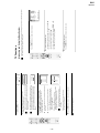
CAUTION
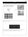
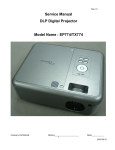
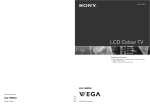
Lead Free Soldered Boards
example 1
The circuit boards listed below [Table 1] used in these models
may have been processed using Lead Free Solder. The boards are
identified by the LF logo located close to the board designation
e.g. F1, H1 etc [ see examples ]. The servicing of these boards
requires special precautions to be taken as outlined below.
example 2
Table 1
Board
Function
A
Tuner, Audio, Chroma Decoder, Scar t 1
G
Power Supply
H1
Control Buttons
H2
Front Input, HP Output
H3
Scar t 2
H5
IR Receiver & LED's
It is strongly recommended to use Lead Free Solder material in order to guarantee optimal quality of new solder joints. Lead Free Solder is
available under the following part numbers :
Partnumber
Diameter
Remarks
7-640-005-19
0.3mm
0.25Kg
7-640-005-20
0.4mm
0.50Kg
7-640-005-21
0.5mm
0.50Kg
7-640-005-22
0.6mm
0.25Kg
7-640-005-23
0.8mm
1.00Kg
7-640-005-24
1.0mm
1.00Kg
7-640-005-25
1.2mm
1.00Kg
7-640-005-26
1.6mm
1.00Kg
Due to the higher melting point of Lead Free Solder the soldering iron tip temperature needs to be set to 370 degrees centigrade. This
requires soldering equipment capable of accurate temperature control coupled with a good heat recovery characteristics.
For more information on the use of Lead Free Solder, please refer to http://www.sony-training.com
-3-
WA1
RM-Y1108
ITEM MODEL
AEP
Television System
Stereo System
Channel Coverage
B/G/H, D/K, I, L
GERMAN/NICAM
Stereo
VHF : E2-12, R1-R12, S01-S03, F02-F10, B-Q
UHF : E21-69, F21-F69, B21-B69, R21-R69
CABLE TV : S01-S20
HYPER : S21-S41
Color System
PAL, SECAM
NTSC3.58, NTSC4.43
(VIDEO IN)
Sound output
Flat Panel
LCD(Liquid Crystal Display)
20 inches (approx. 51cm measured
diagonally).
Right and Left speaker
3W
General Specifications
Input/Output Terminals [REAR]
Inputs for Audio and Video signals.
1: 21-pin Euro connector Inputs for RGB.
(CENELEC standard)
Outputs of TV Video and Audio
signals.
Inputs for Audio and Video signals.
Inputs for S Video.
2: 21-pin Euro connector Outputs of TV Video and Audio signals.
(selectable).
Smar tlink interface.
Phono Jacks
Variable Output for audio signals
Input/Output Terminals [SIDE]
Headphone jack
Audio inputs
Video inputs
S Video input
stereo mini jack
phono jacks
phono jacks
4 pin mini DIN
Power Requirements
220 - 240V
Power Consumption
65W/0.5W
Dimensions
Approx 504x509x250mm
Weight
9Kg
RM-Y1108 Remote Commander (1)
IEC designated R6 battery (2)
Supplied Accessories
Mains (type C-6) Cable (1)
Mains (type BF) Cable (1)
Teletext, Smar tlink, Sleep Timer, Picture
Other Features
Freeze, TV system autodetection.
Remote Control System : Infrared Control
Power requirements
3V dc
2 batteries IEC designation
R6 (size AA)
Design and specifications are subject to change without notice.
Model Name
Item
KLV-20SR3
PAP
OFF
PAT
OFF
RGB Priority
ON
DRC
OFF
Scar t 1
ON
Scar t 2
ON
Front in (3)
ON
Projector
OFF
Norm B/G
ON
Norm I
ON
Norm D/K
ON
Norm AUS
OFF
Norm L
ON
Norm SAT
OFF
Norm M
OFF
Teletext
ON
Nicam Stereo
ON
-4-
WA1
RM-Y1108
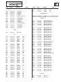
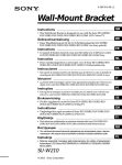
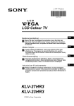
21 pin connector
Pin No
1
2
3
4
1
21
Signal
Signal level
Audio output B
(right)
Standard level : 0.5V rms
Output impedence : Less than 1kohm*
2
Audio input B
(right)
Standard level : 0.5V rms
Output impedence : More than 10kohm*
3
Audio output A
(left)
Standard level : 0.5V rms
Output impedence : Less than 1kohm*
4
Ground (audio)
5
Ground (blue)
20
6
Audio input A
(left)
18
7
Blue input
0.7 +/- 3dB, 75 ohms positive
8
Function select
(AV control)
High state (9.5-12V) : Part mode
Low state (0-2V) : TV mode
Input impedence : More than 10K ohms
Input capacitance : Less than 2nF
19
17
16
15
Standard level : 0.5V rms
Output impedence : More than 10kohm*
14
13
12
11
10
9
8
7
6
5
9
Ground (green)
10
Open
11
Green
12
Open
13
Ground (red)
14
Ground (blanking)
_
4
3
Red input
0.7 +/- 3dB, 75 ohms, positive
(S signal Chroma
input)
0.3 +/- 3dB, 75 ohms, positive
16
Blanking input
(Ys signal)
High state (1-3V) Low state (0-0.4V)
Input impedence : 75 ohms
17
Ground (video
output)
18
Ground (video
input)
19
Video output
1V +/- 3dB, 75ohms, positive sync 0.3V
(-3+10dB)
Video input
1V +/- 3dB, 75ohms, positive sync 0.3V
(-3+10dB)
Video input
Y (S signal)
1V +/- 3dB, 75ohms, positive sync 0.3V
(-3+10dB)
15
_
_
2
1
Green signal : 0.7 +/- 3dB, 75 ohms,
positive
_
20
_
_
21
Common ground
(plug, shield)
Connected
Rear Connection Panel
Not Connected (open)
* at 20Hz - 20kHz
Side Connection Panel
S-Video
socket
S Video socket pin configuration
-5-
Pin
No
Signal
Signal Level
-
1
Ground
2
Ground
-
3
Y (S signal) input
1V+/- 3dB 75ohm,
positive Sync. 0.3V
-3 +10dB
4
C (S signal) input
0.3V+/- 3dB
75ohm, positive
Sync.
WA1
RM-Y1108
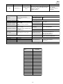
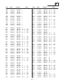
WA1 SELF DIAGNOSTIC SOFTWARE
The identification of errors within the WA1 chassis is triggered in one of two ways :- 1: Busy or 2: Device failure to respond to IIC. In the event
of one of these situations arising the software will first try to release the bus if busy (Failure to do so will report with a continuous flashing
LED) and then communicate with each device in turn to establish if a device is faulty. If a device is found to be faulty the relevant device number
will be displayed through the LED (Series of flashes which must be counted).
Flash Timing Example : e.g. error number 3
StBy LED
ON
ON
OFF
OFF
LED Error Code
LED
ERROR
CODE
02
ERROR DESCRIPTION
A Board Error
03
B Board Error
04
Panel Error
05
EEPROM Error
06
IIC Bus Error
09
Tuner Error
10
Sound Processor Error
11
Panel TV-SVP Error
12
CXA2163 Error
13
Por t Expander 1 Error
14
Por t Expander 2 Error
-6-
–7–
VCR
For more details regarding VCR connection, refer to “Connecting Equipment to the TV” on page 36.
Make sure to connect the aerial before the Scart.
or
Connecting the Aerial and VCR
4
3
2
• To avoid wrong teletext characters for cyrillic languages we
recommend selecting Russia if your own country does not
appear in the list.
• If the country in which you want to use the TV set does not
appear in the list, select “-” instead of a country.
The Country menu appears automatically. Press the v or V button
to select the country in which you are using the TV. Press the OK
button to confirm your selection.
Press the V, v, B or b buttons on the remote control to select your
language, then press the OK button to confirm your selection. From
now on all the menus will appear in your chosen language.
The first time that the TV set is connected, it is usually
turned on. If the TV is off, press the
on/off button to
turn on the TV.
The first time you switch on the TV, a Language menu
appears automatically on the TV screen.
AC, 50Hz).
1 Connect the TV plug to the mains socket (220-240V
United Kingdom
Ireland
Nederland
België/Belgique
Luxembourg
France
Italia
Schweiz/Suisse/Svizzera
Deutschland
Österreich
Select country
Country
The first time you switch on your TV, a sequence of menu screens appear on the TV enabling you to: 1) choose
the language of the menu screen 2) choose the country in which you are going to operate the TV, 3) search and
store all available channels (TV Broadcast) and 4) change the order in which the channels (TV Broadcast)
appear on the screen.
However, if you need to change any of these settings at a later date, you can do that by selecting the appropriate
option in the
(Set Up menu) or by pressing and holding the Auto Start Up button
on the top of TV set
for more than three seconds, see page 17.
Switching On the TV and Automatically Tuning
First Time Operation
The operating instructions mentioned here are partial abstracts
from the Operating Instruction Manual. The page numbers of
the Operating Instruction Manual remain as in the manual.
RM-Y1108
WA1
SECTION 1 GENERAL
–8–
v or V button to select the programme
the order of the other channels.
3 Repeat steps b)1 and b)2 if you wish to change
The selected channel now moves to its new
programme position and the other channels move
accordingly.
2 Press the
v or V button to select the new
programme number position for your selected channel
(TV Broadcast). Press the OK button to store
number with the channel (TV Broadcast) you wish
to move. Press the b button.
1 Press the
b) If you wish to store the channels in a different order:
go to step 8.
a) If you wish to keep the broadcast channels in the tuned order,
After all available channels are captured and stored,
the Programme Sorting menu automatically appears
on the screen enabling you to change the order in
which the channels are stored.
Your TV set is now ready for use
8 Press the MENU button to remove the menu from the screen
7
If no channels were found during the auto tune process, a
message appears automatically on the screen asking you to
connect the aerial. Check the aerial connection (refer to
page 20). Press the OK button to restart the auto tuning
process.
This procedure could take some minutes. Please be patient
and do not press any buttons, otherwise automatic tuning
will not be completed.
available broadcast channels for you.
6 The TV starts to automatically search and store all
button to select Yes.
5 The Auto Tuning menu appears on the screen. Press the OK
Auto tuning
Confirm
01
02
03
04
05
06
07
08
09
10
11
TVE
TVE2
TV3
C33
C27
C58
S02
S06
C44
C47
C48
01
Programme Sorting
TVE
TVE2
TV3
C33
C27
C58
S02
S06
C44
C47
C48
Programme Sorting
01
02
03
04
05
06
07
08
09
10
11
No
Exit:
TVE
Exit:
No channel found.
Please connect aerial
Programmes found:
Yes
Do you want to start
automatic tuning?
MENU
MENU
3
2
1
v or V.
Press the MENU button to remove the menu from the screen.
To switch off the menu screens:
• To confirm and store your selection, press OK.
• To alter the settings of your selected option, press v/V/B or b.
• To return to the last menu or option, press B.
• To enter the selected menu or option, press b.
• To highlight and select the desired menu or option, press
To navigate through the menus:
Press the MENU button to switch the first level menu on.
To switch on the menu screens:
Select:
Set:
OK
Picture Mode
Contrast
Brightness
Colour
Sharpness
Backlight
Reset
Noise Reduction
Colour Tone
Picture Adjustment
End:
MENU
Auto
Normal
Personal
80
50
50
50
70
Your TV set uses an On-Screen menu system to guide you through the operations. Use the following buttons
on the Remote Control to operate the menu system:
Introducing and Using the Menu System
TV Functions
RM-Y1108
WA1
Select:
Set:
OK
Picture Mode
Contrast
Brightness
Colour
Sharpness
Backlight
Reset
Noise Reduction
Colour Tone
Picture Adjustment
MENU
,
Set:
OK
Back:
End:
Auto
Normal
Personal
80
50
50
50
70
MENU
(for films).
Once you have selected your desired option, press OK to store.
Movie
Live
(for live broadcast programmes, DVD and Digital Set Top Box
receivers).
Personal (for individual settings).
This option allows you to customise the picture mode based on the programme
you are watching. After selecting this option press OK. Next, press repeatedly v
or V to select:
Select:
Picture Mode
Contrast
Brightness
Colour
Sharpness
Backlight
Reset
Noise Reduction
Colour Tone
Picture Adjustment
–9–
Press B or b to darken or brighten the picture. Next, press OK to store.
Brightness
Press B or b to decrease or to increase the green tones. Next press OK to store.
Press B or b to darken or brighten the backlight.
continued...
This option only appears and can only be adjusted if “Picture Mode” is set to “Personal”.
Backlight
This option only appears and can only be adjusted if “Picture Mode” is set to “Personal”.
Press B or b to soften or to sharpen the picture. Next press OK to store.
This option only appears for NTSC signal (e.g. USA video tapes).
Sharpness
Hue
Press B or b to decrease or to increase color intensity. Next press OK to store.
This option only appears and can only be adjusted if “Picture Mode” is set to “Personal”.
Colour
This option only appears and can only be adjusted if “Picture Mode” is set to “Personal”.
Press B or b to reduce or enhance picture contrast. Next, press OK to store.
Contrast
"Brightness", "Colour", "Sharpness" and "Backlight" level of "Live" and "Movie" mode are
fixed on the factory to get the best picture quality.
Picture Mode
End:
Auto
Normal
Personal
80
50
50
50
70
To do this:
Press the MENU button and then press OK to
enter this menu. Next, press v or V to select the
desired option and press OK. Finally, read below
how to operate into each option.
The “Picture Adjustment” menu allows you to
alter the picture settings.
The Picture Adjustment Menu
Colour Tone
Noise
Reduction
Reset
This option allows you to alter the tint of the picture. After selecting this option press b. Next, press
repeatedly v or V to select: Warm (gives the white colours a red tint), Normal (gives the white
colours a neutral tint), Cool (gives the white colours a blue tint). Finally press OK to store.
This option is set to Auto to automatically reduce the snowy picture visible in the weak broadcast
signal. However, it can be modified. After selecting this option press b. Next, press v or V to
select Off. Finally, press OK to store.
Press OK to reset the picture to the factory preset levels.
RM-Y1108
WA1
Select:
Set:
OK
OK
m
Set:
Sound Effect
Treble
Bass
Balance
Reset
Dual Sound
Auto Volume
Sound Adjustment
Select:
Picture Mode
Contrast
Brightness
Colour
Sharpness
Backlight
Reset
Noise Reduction
Colour Tone
Picture Adjustment
MENU
MENU
– 10 –
Select:
Set:
OK
Back:
Stereo
Off
Natural
0
0
0
End:
MENU
Flat response.
Press B or b to emphasise the left or the right speaker. Next, press OK to store.
Press OK to reset the sound to the factory preset levels.
Balance
Reset
This function has no effect on headphones sound.
Press b. Next press v or V to select On (the volume level of the channels will
stay the same, independent of the broadcast signal, e.g. in the case of advertisements)
or Off (the volume level changes according to the broadcast signal). Next press OK to
store.
* The “BBE High Definition Sound system” is manufactured by Sony Corporation under license
from BBE Sound, Inc. It is covered by U.S. Patent No. 4,638,258 and No. 4,482,866. The word
“BBE” and BBE Symbol are trademarks of BBE Sound, Inc.
Auto
Volume
Press b. Next:
• For a Stereo broadcast:
Press v or V to select Stereo or Mono. Next press OK to store.
• For a bilingual broadcast:
Press v or V to select Mono (for mono channel if available), A (for channel 1) or B
(for channel 2). Next press OK to store.
Press B or b to decrease or to increase the lower-frequency sounds. Next, press OK
to store.
Bass
Dual
Sound
Press B or b to decrease or to increase higher-frequency sounds. Next, press OK to
store.
This function has no effect on headphones sound.
Once you have selected your desired option, press OK to store.
Off
Dynamic “BBE High Definition Sound system”* intensifies clarity and presence of
sound for better intelligibility and musical realism.
Natural Enhances clarity, detail and presence of sound by using “BBE High
Definition Sound system”*.
This option allows you to customise the sound effect. After selecting this
option press OK. Next, press repeatedly v or V to select:
,
Sound Effect
Treble
Bass
Balance
Reset
Dual Sound
Auto Volume
Sound Adjustment
To do this:
Press the MENU button and press v to select
, then press OK to enter this menu. Next,
press v or V to select the desired option and
press OK. Finally, read below how to operate
into each option.
The “Sound Adjustment” menu allows you to
alter the sound settings.
Treble
Sound
Effect
End:
Stereo
Off
Natural
0
0
0
End:
Auto
Normal
Personal
80
50
50
50
70
The Sound Adjustment Menu
Select:
Set:
OK
OK
m
Set:
Power Saving
AV2 Output
TV Speakers
RGB Center
Features
Select:
Picture Mode
Contrast
Brightness
Colour
Sharpness
Backlight
Reset
Noise Reduction
Colour Tone
Picture Adjustment
MENU
MENU
,
Set:
OK
Back:
End:
Standard
Auto
On
0
MENU
Press the MENU button and press v twice to
select
, then press OK to enter this menu.
Next, press v or V to select the desired option
and press OK. Finally, read below how to
operate into each option.
To do this:
The “Features” menu allows you to alter
various settings of the TV.
• If you select “AUTO”, the output signal will always be the same one that is displayed on
the screen.
• If you have connected a decoder to the Scart
2/ S 2 or to a VCR connected to this
Scart, please remember to change back the "AV2 Output" to “TV” for correct
unscrambling. Alternatively, set the "Decoder" option in the "Manual Programme Preset"
menu to "On" for the scrambled programme. For more details refer to page 33.
To do this:
Once you have entered into the "Features" menu as it is explained in the previous page and after
selecting the option, press OK. Then press v or V to select the desired output signal:
TV
to output the aerial source.
AUTO to output the signal that is being viewed on the TV.
If your VCR or DVD recorder supports SmartLink, this procedure is not necessary.
AV2 OUTPUT
The "AV2 Ouptut" option allows you to select the source to be output from the Scart connector
2/ S so that you can record from this Scart the signal coming from the TV or the signal that
is being viewed on the TV.
This option allows you to reduce the power consumption of this TV.
To do this:
After selecting the option, press OK. Then, press v or V to select Reduce. Next, press OK to store.
Select:
Power Saving
AV2 Output
TV Speakers
RGB Center
Features
POWER SAVING
End:
Standard
Auto
On
0
End:
Auto
Normal
Personal
80
50
50
50
70
The Features Menu
RM-Y1108
WA1
The TV speakers are temporarily turned off allowing you to listen to the sound from external
audio equipment.
One Time Off
The TV speakers are permanently turned off allowing you to listen to the sound from external
audio equipment.
– 11 –
To do this:
Once you have entered the "Features" menu as it is explained in on page 28 and while watching an RGB source select
the “RGB Center” option and press OK. Then press B or b to adjust the centre of the picture between –5 and +5.
Finally press OK to confirm and store.
This option is only available if an RGB source has been connected to the Scart connector
1/
on the
rear of TV.
When viewing an RGB signal, the picture may need some adjusting. This option allows you to adjust the horizontal
picture position so that the picture is in the middle of the screen.
RGB CENTER
To turn on the TV speakers again, change the "TV Speakers" option to "On".
Permanent Off
The "TV Speakers" option automatically returns to "On" when the TV set is switched off.
The sound is output from the TV speakers.
On
To do this:
Press the v or V buttons to select one of the following options, then press the OK button.
This option allows you to turn off the TV speakers e.g. to listen to the sound through external audio equipment connected to the TV.
TV SPEAKERS
OK
m
Set:
End:
MENU
Auto
Normal
Personal
80
50
50
50
70
Set:
OK
MENU
,
Set:
OK
Back:
End:
MENU
Language
English
United Kingdom
Country
Auto Tuning
Programme Sorting
Programme Labels
AV Preset
Manual Programme Preset
Select:
Set Up
To do this:
Press the MENU button and press v three times
to select
, then press OK to enter this menu.
Next, press v or V to select the desired option
and press OK. Finally, read below how to
operate into each option.
The “Set Up” menu allows you to alter various
options on this TV.
To do this:
After selecting the option, press OK and then proceed in the same way as in the step 7 of the section
“Switching On the TV and Automatically Tuning” on page 23.
PROGRAMME SORTING
This option allows you to change the order in which the channels (TV Broadcast) appear on the
screen.
To do this:
After selecting the option, press OK and then proceed in the same way as in the steps 5 and 6 of the
section “Switching On the TV and Automatically Tuning” on page 23.
AUTO TUNING
This option allows you to automatically search for and store all available TV channels.
To do this:
After selecting the option, press OK and then proceed in the same way as in step 4 of the section
"Switching On the TV and Automatically Tuning" on page 22.
COUNTRY
This option allows you to select the country in which you wish to operate the TV set.
To do this:
After selecting the option, press OK and then proceed in the same way as in step 3 of the section
"Switching On the TV and Automatically Tuning" on page 22.
LANGUAGE
This option allows you to select the language that menus are displayed in.
End:
Language
English
Country
United Kingdom
Auto Tuning
Programme Sorting
Programme Labels
AV Preset
Manual Programme Preset
Select:
Set Up
Select:
Picture Mode
Contrast
Brightness
Colour
Sharpness
Backlight
Reset
Noise Reduction
Colour Tone
Picture Adjustment
The Set Up Menu
RM-Y1108
WA1
• To correct a letter, select "%" on the screen to go back and press OK.
• For a blank, select " " on the screen and press OK.
With the first element of the Label column highlighted, press OK and v, V, B or b to select the letter, next
press OK.
When you have finished, press v, V, B or b to select the word “End” on the screen and finally press OK to
turn off the menu from the screen.
– 12 –
• To correct the letter, select "%" on the screen to go back and press OK.
• For a blank, select " " on the screen and press OK.
b) If you want to set a different label, select Edit and press OK. Then, with the first element highlighted, press
v, V, B or b to select the letter, next press OK. When you have finished, press v, V, B or b to select
the word “End” on the screen and finally press OK to turn off the menu from the screen.
The total predefined labels are: VIDEO, DVD, CABLE, GAME, CAM (camcorder) or SAT
(satellite).
A label automatically appears in the label column:
a) If you want to use one of the predefined labels, press v or V to select the desired label and finally press OK.
continued...
To do this:
Once you have entered the "Set Up" menu as it is explained in the previous page and after selecting this option
press OK, then press v or V to select the input source you want to alter the input sound level: AV1 and AV2
for the rear Scarts and AV3 for side connectors. Next press twice b to highlight the Sound Offset column.
Finally press OK and v or V to alter the input sound level between -9 and +9.
b) Change the input sound level of the optional equipment connected.
2
1
To do this:
Once you have entered the "Set Up" menu as it is explained in the previous page and after selecting this option,
press OK, then press v or V to select the input source you wish to name: AV1 and AV2 for the rear Scarts
and AV3 for side connectors. Next press OK twice.
a) Designate a name to the external equipment you have connected to the input sockets of the TV set.
AV PRESET
This option allows you to:
2
To do this:
1 Once you have entered the "Set Up" menu as it is explained in the previous page and after selecting this option,
press OK, then press v or V to select the programme number with the channel you wish to name. Next press OK.
PROGRAMME LABELS
This option allows you to name a channel using up to five characters (letters or numbers).
OK
m
Set:
End:
MENU
Auto
Normal
Personal
80
50
50
50
70
OK
End:
MENU
,
Set:
OK
Back:
MENU
To do this:
Press the MENU button and press v three times
to select
, then press OK to enter the "Set
Up" menu. Next, press v or V to select
"Manual Programme Preset" and press OK.
Finally, read below how to operate into each
option.
The “Manual Programme Preset” option in the
"Set Up" menu allows you to manually tune
individual channels.
After selecting the Channel option, press OK. Next press v or V to select the channel tuning ("C" for
terrestrial channels or "S" for cable channels). Then press the number buttons to enter directly the channel
number of the TV Broadcast or the channel of the VCR signal. If you do not know the channel number, press
b and v or V to search for it. When you have tuned the desired channel, press OK twice to store.
The following option is only available depending on the country you have selected in the “Country”
menu.
After selecting the System option, press OK. Then press v or V to select the TV Broadcast system (B/G for
western European countries, D/K for eastern European countries, L for France or I for United Kingdom).
Then press B.
• To correct a letter, select "%" on the screen to go back and press OK.
• For a blank, select " " on the screen and press OK.
To do this:
Once you have entered the “Set Up”menu as it is explained on page 30 and after selecting the "Manual
Programme Preset" option, press OK. Next with the Programme option, highlighted press the PROG +/- button
to select the programme number with the channel you wish to name. When the programme you want to name
appears on the screen, press v or V to select the Label option and press OK. Then, with the first element
highlighted, press v, V, B or b to select the letter, next press OK. When you have finished, press v, V, B or
b to select the word “End” on the screen and finally press OK to turn off the menu from the screen. Finally press
OK to store.
b) Label a channel using up to five characters.
Repeat all the above steps to tune and store more channels.
3
2
1
To do this:
Once you have entered the “Set Up”menu as it is explained on page 30 and after selecting the "Manual
Programme Preset" option, press OK. Next with Programme option highlighted press OK.
Press v or V to select which programme number you want to preset the channel on (for VCR, select
programme number “0”). Then press B.
a) Preset channels or the VCR channel one by one to the programme order of your choice.
End:
Language
English
United Kingdom
Country
Auto Tuning
Programme Sorting
Programme Labels
AV Preset
Manual Programme Preset
Select:
Set Up
The Manual Programme Preset option allows you to:
Set:
Language
English
Country
United Kingdom
Auto Tuning
Programme Sorting
Programme Labels
AV Preset
Manual Programme Preset
Select:
Set Up
Select:
Picture Mode
Contrast
Brightness
Colour
Sharpness
Backlight
Reset
Noise Reduction
Colour Tone
Picture Adjustment
The Manual Programme Preset Menu
RM-Y1108
WA1
– 13 –
f)
To cancel this function afterwards, select "Off" instead of "On" in the step above.
To do this:
Once you have entered the "Set Up" menu as it is explained on page 30 and after selecting the "Manual
Programme Preset" option, press OK. Next press v or V to select the Decoder option and press b. Next press
v or V to select On. Finally press OK twice to confirm and store.
This option is only available depending on the country you have selected in the “Country” menu.
View and record scrambled channels (e.g. from a pay TV decoder) when using a decoder connected to Scart
2/ S directly or through a VCR.
To cancel this function afterwards, select “Off” instead of “On” in the step above.
To do this:
Once you have entered the "Set Up" menu as it is explained on page 30 and after selecting the "Manual
Programme Preset" option, press OK. Next with the Programme option highlighted, press the PROG +/- button
to select the programme number you want to skip. When the programme you want to skip appears on the screen,
press v or V to select the Skip option and press b. Next press v or V to select On. Finally press OK twice to
confirm and store.
e) Skip any unwanted programme numbers when they are selected with the PROG +/- buttons.
You can not receive stereo or dual sound when “Low” or “High” is selected.
To do this:
Once you have entered the “Set Up” menu as it is explained on page 30 and after selecting the “Manual
Programme Preset” option, press OK. Next, press v or V to select the Audio Filter option and press b. Next
press v or V to select Off, Low or High.
“System” is set to “L”.)
Sometimes a non standard broadcast signal can cause sound distortion or intermittent sound muting when
watching mono programmes. The Audio Filter option allows you to reduce this effect.
If you do not experience any sound distortion, we recommend that you leave the Audio Filter option set
to the default setting of “Off”.
d) Improve the sound for individual channels in the case of distortion in mono broadcasts. (Not available when
To do this:
While watching the channel (TV Broadcast) you wish to fine tune, and once you have entered the “Set Up” menu
as it is explained on page 30 and after selecting the "Manual Programme" option, press OK. Then press v or V
to select the AFT option and press b. Next press v or V to adjust the fine tuning between -15 and +15. Finally
press OK twice to store.
however you can manually fine tune the TV to obtain a better picture reception in case the picture is distorted.
c) Fine tune the broadcast reception. Normally the automatic fine tuning (AFT) will give the best possible picture,
button on the remote control repeatedly until “Off” appears on the screen.
To do this
With the TV in Picture Freeze mode, press the B, b, v or V buttons to adjust the position of the
window on the TV screen.
Adjusting the position of the Picture Freeze window
The position of the window displaying the currently selected channel can be adjusted.
To do this:
Press the
button on the remote control to freeze the picture. A window is displayed in the
bottom left of the screen showing the currently selected channel. Press the
button again to
remove the window. Press the
button again to cancel the Picture Freeze and return to normal
TV mode.
This function allows you to freeze the TV picture (e.g. to make a note of a telephone number or
recipe).
Picture Freeze
• If you switch off the TV and switch it on again, the Sleep Timer feature is reset to “Off”.
• Press the
button on the remote control to display the time remaining before the TV
switches to standby mode.
• The message “Sleep Timer will end soon. Power will be turned off.” Appears on the screen
1 minute before the TV switches to the standby mode.
Press the
To cancel the Sleep Timer feature:
(Standby/Sleep) indicator on the TV lights up in red.
button on the remote control repeatedly until the desired time period appears on the
When the Sleep Timer feature is on, the
Press the screen.
To do this:
This function allows you to set the TV to switch itself automatically to standby mode after a
specified time period. The following time periods can be selected: 30, 60, 90 and 120 minutes.
Sleep Timer
Other Functions
RM-Y1108
WA1
Teletext
Teletext Superimpose mode t TV mode t Teletext mode t (repeat).
, the screen changes cyclically as follows:
.
– 14 –
repeatedly to choose between four different options of
The Fastext service lets you access pages with one push of a button.
Whilst you are in the Teletext mode and Fastext is broadcast, a colour coded menu appears
at the bottom of the Teletext page. Press the colour button (red, green, yellow or blue) to
access the corresponding page.
Fastext
If wrong Teletext characters appear for Cyrillic languages, we recommend you set the
"Language" option in the "Set Up" menu to "Russia" if your country does not appear in the
list. For details, refer to page 30.
To switch off Teletext
Press
.
To change brightness of Teletext:
Whilst you are viewing Teletext, press
brightness.
To reveal concealed information (e.g. answers to a quiz)
Press
/ . Press it again to conceal the information.
To freeze a Teletext page
Some Teletext pages have sub-pages which follow on automatically. To stop them, press
/ . Press it again to cancel the freeze.
To access the next or preceding page
Press PROG + ( ) or PROG - ( ).
To select a Teletext page
Input three digits for the page number, using the number buttons.
• If you make a mistake, retype the correct page number.
• If the counter on the screen continues searching, it is because this page is not available. In this
case, input another page number.
Teletext mode
Each time you press
To switch on Teletext
After selecting the TV channel which carries the Teletext service you want to view, press
Make sure you use a channel (TV Broadcast) with a strong signal, otherwise Teletext errors may
occur.
Teletext is an information service transmitted by most TV stations. The index page of the
Teletext service (usually page 100) gives you information on how to use the service. To operate
Teletext, use the remote control buttons as indicated below.
E
To avoid snowy
picture, do not connect
external equipment to
connectors A and B
at the same time.
Hi-fi
8mm/Hi8/
DVC
camcorder
o3
3
D
C
B
Computer Entertainment, Inc.
* “PlayStation” is a trademark of
Sony Computer Entertainment, Inc.
* “PlayStation” is a product of Sony
A
3
F
G
PlayStation
2
DVD
Decoder
Decoder
“PlayStation”*
DVD recorder
VCR
S VHS/Hi8/
DVC
camcorder
• Using the following instructions you can connect a wide range of optional equipment to your TV set.
• Connecting cables are not supplied.
Connecting Equipment to the TV
Additional Information
RM-Y1108
WA1
2/
S
F or through a
The volume of the external speakers can be altered by pressing the volume buttons on the TV remote control.
The treble and bass setting can also be altered through the “Sound Adjustment” menu (see page 27).
To listen to the sound from TV on Hi-fi equipment.
Connect your audio equipment to the audio output sockets E if you wish to amplify the audio output from the TV.
Next, using the menu system, select the “Features” menu and set the “TV Speakers” to "Permanent Off" (see page
29).
Connecting Audio Equipment to the TV
**This option is only available depending on the country you have selected in the “Country” menu.
Select the “Manual Programme Preset” option in the “Set Up” menu and after entering in the “Decoder**” option,
select “On” (refer to page 33). Repeat this option for each scrambled signal.
If you have connected a decoder or a Set Top Box to the Scart
VCR connected to this Scart
If you use a VCR or a DVD recorder that supports SmartLink, please connect the VCR or the DVD recorder to the
TV using a Scart lead to the Scart
2/ S F.
SmartLink is a direct link between the TV set and a SmartLink compatible VCR/DVD recorder. For more
information on SmartLink, please refer to the instruction manual of your SmartLink VCR/DVD recorder.
Connecting a VCR or a DVD recorder that supports SmartLink
To connect a VCR, please refer to the section “Connecting the aerial and VCR” of this instruction manual on page 20.
Connecting a VCR
– 15 –
• Video input signal through the phono socket B and Audio input signal through
C.
• S Video Input signal through the side S Video input jack A and Audio signal
through C. This symbol appears only if an S Video source has been connected.
3
3
button on the remote control to return to the normal TV picture.
• S Video Input signal through the Scart connector F. This symbol appears only
if an S Video source has been connected.
• Audio/video input signal through the Scart connector F.
2
2
• RGB input signal through the Scart connector G. This symbol appears only if
an RGB source has been connected.
Press the
S
S
• Audio / video input signal through the Scart connector G
button repeatedly until
1
Input Signals
/
1
Symbol
To watch the picture from the connected equipment, press the
the correct input symbol appears on the screen.
Switch on the connected equipment.
Connect your equipment to the designated TV socket, as indicated on page 36.
For Mono Equipment
Connect the phono plug to the L/G/S/I socket on the side of the TV and select
3 or S 3
input signal using the instructions above. Next, refer to the “Sound Adjustment” section of this
manual and set “Dual Sound” option to “A” on the sound menu screen (see page 27).
4
3
2
1
Viewing pictures from equipment connected to the TV
RM-Y1108
WA1
– 16 –
Weight:
With stand, approx. 9 Kg.
Without stand, approx. 7 Kg.
Dimensions (w x h x d):
With stand, approx. 504 x 509 x 250 mm.
Without stand, approx. 504 x 467 x 111 mm.
Sound Output:
3W
Standby Power Consumption:
0.5 W
Power Consumption:
65 W
Power Requirement:
220-240V AC; 50/60 Hz
Display Resolution:
640 dots (horizontal) x 480 lines (vertical)
Screen Size:
20 Inches (approx. 51 cm. measured diagonally)
Channel Coverage:
(Depending on the Country/region selection)
VHF:
E2-E12
UHF:
E21-E69
CATV:
S1-S20
HYPER:
S21-S41
D/K:
R1-R12, R21-R69
L:
F2-F10, B-Q, F21-F69
I:
UHF B21-B69
Aerial:
75 ohm external terminal for VHF/UHF
Colour System:
PAL, SECAM
NTSC 3.58, 4.43 (Only Video In)
TV System:
(Depending on the Country/region selection)
B/G/H, D/K, L, I
Panel System:
LCD (Liquid Crystal Display) Panel
Aerial connector (RF In)
•
headphones jack
3 Audio input (phono jacks)
3 Video input (phono jack)
3 S video input (4-pin mini DIN)
This TV is compatible with the VESA universal wall
stand system.
Other Features:
• Teletext, Fastext, TOPtext (depending on
availability)
• Sleep Timer
• Picture Freeze
• Smartlink (Direct link between your TV and a
compatible VCR or DVD recorder. For more
information on Smartlink, please refer to the
instruction manual of your VCR or DVD recorder.)
• TV system autodetection
Accessories supplied:
One Remote Control (RM-Y1108),
Two Size AA batteries (R6 type),
One Mains lead (Type C-6)
One Mains lead (Type BF)
•
S
Side Terminals:
• AV3:
Audio Outputs (left/right) – phono jacks.
•
• AV2:
2/ S (SMARTLINK)
21-pin Scart connector (CENELEC standard)
including audio/video input, S video input, selectable audio/video output and Smartlink interface.
Rear Terminals:
• AV1:
1/
21-pin Scart connector (CENELEC standard)
including audio/video input, RGB input, TV audio/
video output.
This instruction manual has been printed on:
Ecological Paper - Totally Chlorine Free
Design and specifications are subject to change
without notice.
Technical Specifications
Possible solution
• The picture of the display is composed of pixels. Tiny black points
and/or bright points (pixels) on the screen, do not indicate a
malfunction.
• Using the menu system, select the “Picture Adjustment” menu and
select “Picture Mode” Then select the desired picture mode (page
25).
• Make sure that the aerial is connected.
• Keep the aerial cable away from other connecting cords.
• Do not use 300-ohm twin lead cables as interference may occur.
Some tiny black points and/or bright
points on the screen.
The picture is too bright.
Picture (stripe) noise.
• Keep the TV away from electrical noise sources such as cars,
motorcycles, or hair-dryers.
Dotted lines or stripes.
• Using the menu system, select the “Picture Adjustment” menu and
select “Reset” to return to the factory settings (page 26).
• If you set the “Power Saving” function to “Reduce,” picture colours
may become dimmer (page 28).
• Check if the aerial is broken or bent.
• Check if the aerial has reached the end of its serviceable life (3-5
years in normal use, 1-2 years at the seaside)
Only snow and noise appears on
the screen.
No colour on colour programmes.
• Check aerial/cable connections.
• Check the aerial location and direction.
Double images or ghosting.
Poor picture/Unstable picture
/
No picture or no menu information from • Check that the optional equipment is on and press the
button repeatedly on the remote control until the correct input
equipment connected to the Scart
symbol is displayed on the screen (page 38).
connector.
• Check the connection between the optional equipment and the TV.
The TV turns off automatically. (The TV • Check if the Sleep Timer is activated (page 34).
enters the standby mode.)
No picture (screen is dark) and no sound. • Check the aerial connection.
• Connect the TV to the mains, and press the power switch on the
top side of the TV set.
• If the (standby) indicator is on, press TV
on the remote
control.
No picture
Problem
Here are some simple solutions to problems which may affect the picture and sound.
Troubleshooting
RM-Y1108
WA1
– 17 –
Make sure that the aerial is connected.
Keep the aerial cable away from other connecting cables.
Do not use 300-ohm twin lead cables as interference may occur.
Communication problems may occur if the infrared communication
equipment (e.g. infrared cordless headphones) is used near the TV.
Please use headphones other than infrared cordless headphones,
move the infrared transceiver away from the TV until the noise is
eliminated, or move the transmitter and receiver of the infrared
communication equipment closer together.
• Using the menu system, select “Audio Filter” from the “Manual
Programme Preset” menu. Next select “Low” or “High” (see page
33).
•
•
•
•
• Press the 2 +/- or % (mute) on the remote control.
• Check that “TV Speakers” option is set to “On” in the “Features”
menu (page 29).
continued...
Unable to receive a stereo or dual sound • Check that the “Audio Filter” option in the “Manual Programme
Preset” menu is set to “Off”.(see page 33).
broadcast
Audio noise.
Good picture, no sound.
No sound/Noisy sound
• Using the menu system, enter the “Country” option in the “Set Up”
menu and select the country in which you operate the TV set (page
30). For Cyrillic languages, we recommend that you select Russia
if your own country does not appear in the list.
• Turn off any equipment connected to the Scart connector on the rear
of the TV set.
Distorted picture when changing
programmes or selecting teletext.
Wrong characters appear when viewing
teletext
• Using the menu system, select the “Manual Programme Preset”
option in the “Set Up” menu and adjust Fine Tuning (AFT) to
obtain better picture reception (page 33).
• Using the menu system, set the "Noise Reduction" option in the
“Picture Adjustment” menu to reduce the noise in the picture (page
26).
Noisy picture when viewing a TV
channel.
• If the item you want to select appears in a pale colour is because you
cannot select it.
• Using the menu system, select the “Picture Adjustment” menu and
select “Reset” to return to the factory settings (page 26).
Poor or no picture (screen is dark), but
good sound.
Cannot operate the menu
• Video head interference. Keep your VCR away from the TV.
• Leave a space of 30 cm between your VCR and the TV set to avoid
noise.
• Avoid installing your VCR in front or at the side of the TV set.
Possible solution
Stripe noise during playback/recording
of a VCR.
Problem
• Contact your nearest Sony service centre.
• Replace the batteries.
• There might be a surge sound when turning on the TV. This does
not indicate a malfunction.
• Changes in room temperature sometimes causes the TV cabinet to
expand or contract, which can make slight noises. This does not
indicate a malfunction.
Possible solution
• If you continue to experience problems, have your TV serviced by qualified personnel.
• Never open the casing yourself.
The
(standby) or TV (power on)
indicators on the TV flashes
Remote Control
Remote control does not function.
The TV buzzes.
The TV cabinet creaks.
Strange sound
Problem
RM-Y1108
WA1
WA1
RM-Y1108
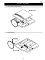
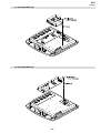
SECTION 2 DISASSEMBLY
2-1. REAR CABINET ASSEMBLY REMOVAL
2-2. STAND REMOVAL
– 18 –
WA1
RM-Y1108
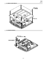
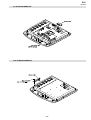
2-3. REAR COVER REMOVAL
2-4. SPEAKER REMOVAL
– 19 –
WA1
RM-Y1108
2-5. A BOARD REMOVAL
2-6. G BOARD REMOVAL
– 20 –
WA1
RM-Y1108
2-7. H1 BOARD REMOVAL
2-8. H2 BOARD REMOVAL
3
4
– 21 –
WA1
RM-Y1108
2-9. H3 BOARD REMOVAL
2-10. H5 BOARD REMOVAL
– 22 –
WA1
RM-Y1108
2-11. LCD BRACKET REMOVAL
2-12. LCD REMOVAL
Four screws
– 23 –
WA1
RM-Y1108
SECTION 3
ADJUSTMENTS
3-1. Signal Adjustment
3-2. White Balance Adjustment
Service adjustments to this model can be performed using the
supplied remote Commander RM-Y1108.
3-2-1. White Balance adjustment (H/L)
1. Select AV1.
2. Change the TV to Personal Mode and set the following registers.
How to enter into the Service Mode
1.
2.
Turn on the power to the TV set and enter into the stand-by
mode.
Press the following sequence of buttons on the Remote
Commander.
i+
5
+
(ON SCREEN
DISPLAY)
(DIGIT 5)
(VOLUME +)
Contrast
Brightness
Colour
Backlight
Press ‘MENU’ on the remote commander to obtain the following
menu on the screen.
TRIDENT PANEL TV
CHROMA DECODER
BACKLIGHT
SOUND
IF ADJUST
ERROR MENU
5.
6.
KLV-20SR3
x
0.2798
y
0.2823
Y
-
range
0.8JN D
Move to the corresponding adjustment item using the
up or down arrow buttons on the Remote Commander.
Press the right arrow button to enter into the required menu item.
Press the ‘Menu’ button on the Remote Commander to quit the
Service Mode when all adjustments have been completed.
Note :
•
After carrying out the service adjustments, to prevent the
customer accessing the ‘Service Menu’ switch the TV set OFF
and then ON.
3-1-1. PAL auto adjustment (CVBS)
1. Select AV1 and input PAL signal.
2. Change the TV to Personal Mode and set the following registers.
Contrast Brightness Colour
-
NORMAL_PAL_RD (R Drive)
NORMAL_PAL_BD (B Drive)
High light adjustment value (10500K-6MPCD)
WA1 v0.21
Factory data FFh FFh
SERIAL NUMBER : 1234567890
4.
Max
50
50
Max
3. Input PAL CVBS 70 IRE Full Field Signal to AV1.
4. Enter the ‘SERVICE MENU’ using the cursor keys on the remote
commander.
5. Adjust Highlight registers:
(TV)
‘TT—’ will appear in the upper right corner of the screen.
Other status information will also be displayed.
3.
-
N /A
3-2-2. White Balance adjustment (C/O)
1. Select AV1.
2. Change the TV to Personal Mode and set the following registers.
Contrast
Brightness
Colour
Backlight
-
Max
50
50
Max
3. Input PAL CVBS 20 IRE Full Field Signal to AV1.
4. Enter the ‘SERVICE MENU’ using the cursor keys on the remote
commander.
5. Adjust CutOff registers:
90
50
50
3. Set the TV in Service Mode (See opposite) and send “TT51”
command.
NORMAL_PAL_RC (R cutoff)
NORMAL_PAL_BC (B cutoff)
3-1-2. PAL auto adjustment (RGB)
1. Select AV1 and input RGB signal.
2. Change the TV to Personal Mode and set the following registers.
Low light (Cut Off) adjustment value (10500K-6MPCD)
KLV-20SR3
Contrast Brightness Colour
-
90
50
50
x
0.2798
y
0.2823
Y
-
range
0.8JN D
3. Set the TV in Service Mode (See opposite) and send “TT52”
command.
- 24 -
N /A
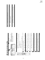
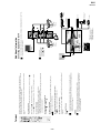
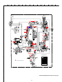
4-1. BLOCK DIAGRAMS (1)
IC3701
ANALOG
MULTIPLEXER/
DE-MULTIPLEXER
CN9200
H-PLUGGED 9
CN9000
1
SWITCH
S9000, S9001
S9002, S9006
TO B BOARD
CN0101
TO A BOARD
CN2211
SWITCH
S9003, S9004,
S9005
3
H1 (
CONTROL
BUTTONS
HP-L-OUT
5
HP-R-OUT
7
CN3703
3
AC IN
L6000
4
C INPUT
13
18
Y INPUT
1
5
Y/C SWITCH
3
VIDEO SWITCH
13
SC2-OUT-R-H3
9
SC2-IN-R-H3
15
SC2-OUT-L-H3
)
3
4
3
SCART 2
Y FRONT
BUFFER
Q3709
Y/CVBS FRONT
C FRONT
BUFFER
Q3708
C FRONT
C SCART
BUFFER
Q3701
C IN
9
5
3
J9300
C FRONT
FRONT INPUT,
HP OUTPUT
11
14
SW OUT
BUFFER
Q3702
VIDEO OUT
Y SCART
BUFFER
Q3707
V
Y/CVBS-FRONT
TO A BOARD
CN3621
2
VIDEO IN
RIGHT OUT
R
)
1
2
3
4
3
2
4
1
BUFFER
Q2700
3
12
IC6000
MAIN BRIDGE RECTIFIER
F/B
VGH 23
SC2-IN-L-H3
2
MODE 2
MODE
1
AV LINK
AV LINK
BUFFER
Q2701
BUFFER
Q6000
VGL 20
1 V SENSE
15
VC1
D6010
PH6001
PHOTOCOUPLER
SWITCH
Q6003
10
9
2
VS 22
8
SWITCH
Q6004
OCP 16
4
IC6001
REGULATOR
D6011
1
Q6001
Q6002
PHOTOCOUPLER
PH6000
BUFFER AMP
Q6005, Q6010,
Q6009
2
IC9050
IR RECEIVER (SIRCS)
3
CN9050
1
STBY 5V
VCC
7
T6001
TO A BOARD
CN0041
12
2
SIRCS
6
LED 2
5
LED 1
OUT
POWER
+16.5V
11
STANDBY
IC6100
STANDBY CONTROLLER/DRIVER
5
4
2
10
9
5V STANDBY
BACKLIGHT
CN6005
2
TO A BOARD
CN6201
POWER-AV
CN6001
11
TO A BOARD
CN6204
STBY 5V
CN6101
2
TO B BOARD
CN6301
3
8
7
8
D6013
SWITCH
Q6006
BUFFER
Q6007
Q6008
4
7
T6100
4
9
5
IC6101
REGULATOR
1
8
2
1
3
PHOTOCOUPLER
PH6100
G(
POWER SUPPLY
- 25 -
)
LEFT IN
11
11
2
RIGHT IN
LEFT OUT
T6000
BRIDGE
RECTIFIER
D6000
CN3702
1
3
CN3700
15
L6007
1
)
10
CN9300
1
(
2
SW MONITOR
20
FRONT IN-L
H2
F6000
4A
22
1
12
FRONT IN-R
L
AC IN
RF-SW
J9201
HEADPHONES
TO H3 BOARD
CN3702
CN6003
1
24
H3 (
H5 (
)
IR RECEIVER
& LED'S
TO H2 BOARD
CN9300
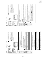
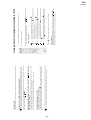
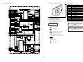
4-1. BLOCK DIAGRAMS (2)
4-2. CIRCUIT BOARD LOCATION
Reference Information
RESISTOR
B
H1
A(
)
TUNER, AUDIO,
CHROMA DECODER,
SCART 1
C
C
N
CN3621
15
SC2-IN-L
17
SC2-IN-R
13
AMPLIFIER
Q3806
SC2-OUT-R
IC3801
SUB VIDEO PROCESSOR
R1-IN 27
BUFFER
Q2600
G1-IN 26
Y FRONT
TO H3 BOARD
CN3703
11
SC2-OUT-L
4
SW MONITOR
BUFFER
Q2601
21
Y/C SWITCH
23
VIDEO SWITCH
24
MODE 2
C FRONT
44
CVBS2/Y2-IN
43
C2-IN
3
CVBS OUT
B1-IN 25
YS3 15
CVBS3/Y2-IN 41
21
Y INPUT
LUMINANCE
6
C INPUT
CHROMINANCE
25
AV LINK
2
RF SW
9
22
23
CN3602
13
RIGHT OUT
SC1-OUT-R
RIGHT IN
SC1-IN-R
LEFT OUT
SC1-OUT-L
LEFT IN
SC1-IN-L
BUFFER
Q3600
CVBS RF
B SCART 1
FB SCART 1
B SCART 1
MODE
MODE 1
GREEN IN
G SCART 1
Y OUT
R SCART 1
BLANKING
FB SCART 1
1
CVBS AV1
14
TO G BOARD
CN6001
19
P6
SCL
2
SCL
SDA
4
SDA
FM/AM
16
P4
QSS
17
P5
DIMMER
CN6204
11
6
29
H5
2
4
H5
A1
D2 A
D1
FRONT-IN-L
SC1-IN-R
SC1-IN-L
SC2-IN-R
SC2-IN-L
: METALIZED POLYPROPYLENE
14
ALB
: BIPOLAR
MODE 2
9
ALT
: HIGH TEMPERATURE
ALR
: HIGH RIPPLE
LUMINANCE
28
CHROMINANCE
25
AV LINK
1
DIMMER
10
TO B BOARD
CN3000
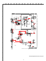
4-3. SCHEMATIC DIAGRAMS AND
PRINTED WIRING BOARDS
Note :
•
•
3
BUFFER
Q0001
LED 1
11
POWER AV
4
SIRCS
3
•
•
•
CN0041
2
5
LED 2
6
+5V STBY
1
All capacitors are in µF unless otherwise noted.
pF : µµF 50WV or less are not indicated except for
electrolytic types.
Indication of resistance, which does not have one for
rating electrical power, is as follows.
Pitch : 5mm
Electrical power rating : 1/4W
TO H5 BOARD
CN9050
Chip resistors are 1/10W
All resistors are in ohms.
k = 1000 ohms, M = 1000,000 ohms
•
: nonflammable resistor.
•
: fusible resistor.
•
: internal component.
•
: panel designation or adjustment for repair.
•
•
•
•
2
SCL
P0 10
4
SDA
P1 11
14
P3
P2 12
16
P4
All variable and adjustable resistors have
characteristic curve B, unless otherwise noted.
All voltages are in Volts.
Readings are taken with a 10Mohm digital mutimeter.
Readings are taken with a color bar input signal.
Voltage variations may be noted due to normal production
tolerences.
Y/C SWITCH
VIDEO SWITCH
•
SC2-OUT-L
SC2-OUT-R
SC1-OUT-L
SC1-OUT-R
FM/AM
TO H2 BOARD
CN9200
BUFFER AMP
Q2100, Q2101
FRONT-IN-L
FRONT-IN-R
5
HP-L-OUT
7
HP-R-OUT
9
HP PLUGGED
QSS
AMPLIFIER
Q2000
.B
:s+
ub
•
: B - bus.
•
: RF signal path.
•
: earth - ground.
XTAL IN 71
•
: earth - chassis.
X2000
48 IN-4-R
XTAL OUT 72
47 IN-4-L
34 OUT-2-L
IC2500
AUDIO POWER AMP
BUFFER
Q2001
SPEAKER OUT R 27
33 OUT-2-R
37 OUT-1-L
2
IN2+
OUT 2 12
OUT 1 7
BUFFER
Q2002
SPEAKER OUT L 28
36 OUT-1-R
60 MONO IN(AM)
4
IN1+
8
MUTE TC
11
MUTE
SP R OUT
CN2500
1
SP L OUT
3
TO SPEAKERS
67 IF IN 1
IC2400
AUDIO LINE BUFFER
IC2300
HEADPHONE AMP
3
R.IN 7
24 HP-R
1
L.IN 6
25 HP-L
77 DIGITAL CONTROL OUT 1
BUFFER
Q2301
BUFFER
Q2300
Q2200
Q2202
Q2204
: POLYPROPYLENE
SDA-5
SCL 2
50 IN-3-L
: STYROL
PP
SDA
SDA 3
51 IN-3-R
: TANTALUM
PS
: METALIZED POLYESTER
IC0001
PORT EXPANDER
POWER ON
21
RESET
53 IN-2-L
: MICRO INDUCTOR
TA
MPP
P1 11
54 IN-2-R
LF-8L
CAPACITOR
12
IC2000
SOUND PROCESSOR
FRONT-IN-R
COIL
SCL-5
A Board
POWER AV
3
D
: ADJUSTMENT RESISTOR
SCL
BUFFER
Q0046
SDA
: NON FLAMMABLE WIREWOUND
: MYLAR
P3 14
+8V
: NON FLAMMABLE CEMENT
RW
MPS
P2 12
3
: NON FLAMMABLE METAL OXIDE
RB
PT
LED 1
1
RS
21
P0 10
2
: NON FLAMMABLE FUSIBLE
20
AMPLIFIER
Q3807
•
+14.3V
: NON FLAMMABLE CARBON
FUSE
CB
AMPLIFIER
Q3809
CR-OUT
SIRCS
SCL
: SOLID
FPRD
CR
CB-OUT
AMPLIFIER
Q1201
IC6202
REGULATOR
CN2211
1
A2
PANEL DET
SWITCH &
BUFFER
Q6200, Q6203
: METAL FILM
RC
J
S1 Board
GA
H3
4
COINCIDENCE
CIRCUIT
IC0030
PORT EXPANDER
AGC DEFEAT
Q1100
BACKLIGHT
Y SYNC
CVM Board
A
IC1200
TV ID
BUFFER
Q1200
3
8
BUFFER
Q0047
RED IN
2
24
MODE 1
AMPLIFIER
Q3808
FB-SCART 1
VIDEO
TO G BOARD
CN6005
CS
CN0043
5
SERVICE
IC0002
DIMMER LPF
BLUE IN
SWITCH
Q0002
4
CVBS MONITOR
CVBS AV1
1
TU1100
CN6201
1
3
CS
H2
VM
H
SCART
AGC
SDA
G SCART 1
AMPLIFIER
Q1300,
Q1301
VIDEO IN
CN0042
2
IC3811
SYNC ADDER
8
VIDEO OUT
R SCART 1
SCL
RN
SWITCH
Q2203
3
7
5
1
L
J2400
R
L
AUDIO OUT
MUTE CIRCUIT
Q2400, Q2401
Q2405, Q2406
R
AMPLIFIER
Q2402
- 26 -
Note : The components identified by shading
and marked
are critical for safety.
Replace only with the part numbers
specified in the parts list.
Note : Les composants identifiés par une trame et
par une marque
sont d'une importance
critique pour la sécurité. Ne les remplacer
que par des pièces de numéro spécifié.
specified.
A
B
C
D
E
F
H
G
I
J
K
L
M
N
O
1
2
C2036
0.0022
3
C2037
0.0022
CN9200
TP1
RB053L
100
TO SPEAKERS
4
100
R2430
0
R2031
100K
5
AUDIO LINE
BUFFER
R2431
0
HEADPHONE
AMPLIFIER
4.7K
4.7K
6
470
0.0022
50V
0.47
7
0.47
+5VSTBY
+5VSTBY
R2210
Q2205
100
MSD601-RST1
+5VSTBY
8
A(1/3) Board Waveform
3.3k
MSD601-RST1
R2209
10K
A
1/3
100ns/div
TP1
TUNER, AUDIO, CHROMA DECODER, SCART 1
9
3.0Vp-p (H)
COMPONENTS MARKED AS XX ARE NOT FITTED ON THIS MODEL
10
~ A Board Schematic Diagram [ Tuner, Audio, Chroma Decoder, Scart 1 ] Page 1/3 ~
11
- 27 -
A
B
C
D
E
F
H
G
I
J
K
L
M
N
O
1
2
R0040
0
3
CN6005
+
4
5
CN6001
6
REGULATOR
R6206
10k
7
220K
CN6300
REGULATOR
8
RD5.6SB-T1
A
2/3
XX
9
COMPONENTS MARKED AS XX ARE NOT FITTED ON THIS MODEL
10
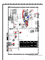
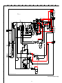
~ A Board Schematic Diagram [ Tuner, Audio, Chroma Decoder, Scart 1 ] Page 2/3 ~
11
- 28 -
A
B
C
D
E
F
H
G
I
J
K
L
M
N
O
1
C2604
470PF
220
2
C2605
470PF
220
XX
CN9050
TP5
TP4
xx
3
TP3
TP2
SERVICE
47
TP1
4
150
R3626
150
SYNC ADDER
SW_MONITOR
Q3801
MSB709-RT1
R3822
1K
L3811
10UH
C3801
0.01
C3802
47
16V
CN3000
5
1.5k
CONTROL AMP
6
A
3/3
7
A(3/3) Board Waveforms
(10us/div)
TP1
8
CN3703
9
(10us/div)
TP2
1Vp-p (H)
(20us/div)
TP3
700mVp-p (H)
(20us/div)
TP4
650mVp-p (H)
(5ms/div)
TP5
650mVp-p (H)
200mVp-p (H)
10
COMPONENTS MARKED AS XX ARE NOT FITTED ON THIS MODEL
~ A Board Schematic Diagram [ Tuner, Audio, Chroma Decoder, Scart 1 ] Page 3/3 ~
11
- 29 -
A
B
C
D
E
F
H
G
I
J
K
L
M
N
O
1
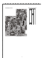
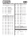
~ A Board Semiconductor Location Table Side A ~
~ A Printed Wiring Board Conductor Side A ~
DIODE
2
3
D3634
H-6
IC
D2402
C-6
D6204
C-3
Q1100
F-6
D2500
D-5
D6205
C-2
Q2205
F-4
D2604
F-6
D6217
H-4
Q2400
C-6
D2605
F-6
Q2401
C-6
D2606
F-6
IC0002
F-4
Q2404
C-6
D2607
G-6
IC2000
G-4
Q2405
C-6
D3626
G-6
IC2400
C-6
Q2406
C-6
D3628
H-6
IC2500
C-4
Q3600
H-6
D3629
G-6
IC3801
I-4
Q3801
I-6
IC
D3630
G-6
IC3811
I-3
Q6200
D-2
D3631
G-6
IC6208
D-3
Q6203
E-2
4
~ A Board Semiconductor Voltage Table ~
5
Ref
(e)(s) (b)(g) (c)(d)
Ref
(e)(s) (b)(g) (c)(d)
Ref
(e)(s) (b)(g) (c)(d)
0
0.4
0
Q2404
0.7
0.1
0.6
Q2406
0
0.4
0
Q6200
0
3.3
0
Q2401
0
0.4
0
Q2405
0
0.4
0
Q3600
2.3
3.0
5.1
Q6009
0
0
10.1
Ref No
Pin No
Volts (V)
7
~ A Board IC Voltage Table ~
Ref No
Pin No
Volts (V)
1
2
Ref No
Pin No
Volts (V)
2.1
5
1.1
6
3
1.1
7
0.1
5
2 .5
8
0.2
6
2.5
9
0.2
7
2.5
10
0.2
Ref No
Pin No
Volts (V)
0.1
21
0.1
24
Ref No
Ref No
Pin No
Volts (V)
Pin No
Volts (V)
4.6
38
7.2
55
0
0
39
8.1
56
3.8
25
0
40
7.1
57
27
0.2
45
3.7
60
28
0.2
47
0.4
65
5.0
30
0.2
48
0.4
66
5.0
Ref No
Pin No
Volts (V)
Ref No
Pin No
Volts (V)
77
0
1
1.7
80
5.0
2
0
IC0002
3.8
1
4.0
3
3.8
2
4.0
4
3
4.0
IC2000
9
IC2000
IC2000
4
0
Pin No
Volts (V)
Ref No
Pin No
Volts (V)
11
0
11
2.5
26
2.5
7.2
12
5.0
27
2.5
0
1
2.4
13
3.5
32
5.0
0
2
2.1
14
3.7
37
1.1
5
1.7
3
1.5
15
0
38
4.0
6
5.4
5
2.1
IC2500
IC2000
IC2500
IC3801
IC3801
20
2.4
1
0
8
5.1
11
5.0
33
3.8
50
3.8
67
1.5
5
4.0
7
7.4
6
5.1
21
1.6
2
0.3
2
3.5
12
5.0
34
3.8
51
3.8
68
1.5
6
4.0
8
5.1
7
2.6
22
1.8
3
0
IC2400
IC2000
Ref No
12
IC2000
IC3801
IC3811
3
3.5
13
5.0
36
3.8
53
3.8
71
2.4
7
4.0
9
15.9
9
0.3
23
1.8
4
4.5
4
0.3
17
0
37
3.8
54
3.8
72
2.3
8
8.1
10
0
10
0.8
25
2.5
5
5.1
10
11
- 30 -
(e)(s) (b)(g) (c)(d)
Q2400
6
8
Ref
A
B
C
D
E
F
G
H
I
J
K
L
M
1
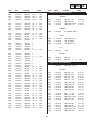
~ A Printed Wiring Board Conductor Side B ~
~ A Board Semiconductor Location Table Side B ~
DIODE
2
3
4
D1200
G-4
8
9
10
11
- 31 -
G-4
IC1200
G-4
Q2100
D-4
E-5
IC2300
E-4
Q2101
D-4
G-4
IC6202
G-2
Q2200
E-4
D2201
G-4
IC6205
I-4
Q2201
G-4
D2202
G-4
Q2202
G-4
D2203
G-4
Q0001
B-5
Q2203
E-5
D2204
G-4
Q0002
F-2
Q2204
G-5
D2205
G-5
Q0046
J-3
Q2205
G-5
D2600
D-6
Q0047
J-3
Q2300
E-4
TRANSISTOR
D3601
D-6
Q1200
F-4
Q2301
E-4
D3627
E-6
Q1201
G-4
Q2600
D-5
D6202
G-3
Q1300
B-5
Q2601
D-6
I-3
Q1301
B-6
Q3806
B-4
Q2000
H-4
Q3808
B-3
Q2001
G-4
Q3809
B-3
IC0001
7
Q2002
D2001
IC
6
G-3
D2200
D6209
5
IC0030
B-5
N
O
A
B
C
D
E
F
H
G
I
J
K
L
M
N
G..-KLV-20SR3
CN6002
10P
WHT
1
C6038
XX
G
1
+16.5V
2
+16.5V
3
+16.5V
4
+16.5V
5
GND
6
GND
7
GND
8
PANEL_DET
9
BACKLIGHT
10
DIMMER
1
PANEL_DET
2
BACKLIGHT
3
DIMMER
4
GND
1
14.3V_B
2
14.3V_B
3
GND
4
GND
5
14.3V_A
6
14.3V_A
7
GND
10
8
GND
9
+33V
9
10
GND
11
POWER_AV
1
GND
2
STBY5V
3
GND
POWER SUPPLY
2
TO LCD
CN0260
CN6005
4P
D6010
FCH10A10
12
1
2
R6006
0.1
1/2W
RF
D6000
D4SB60L-F
C6007
220
450V
R6013
510k
1/10W
R6014
510k
1/10W
21
VB
D6008
XX
GND
Timer
13
NC
14
SS
VGL
PGND
18
Vc2
R6009
110
1/10W
D6004
C6018
MM3Z15VT1 0.01
25V
R6050
47k
R6051
10k
C6034
XX
CN6001
11P
F6001
XX
XX
R6053
10k
1/10W
Q6008
MSD601-RT1
R6052 C6035
XX
47k
1/10W
11
4
D6007 R6026
MM3Z15VT1 10k
1/10W
17
16
OCP
19
15
Vc1
NC
L6004
10uH
JW6001
5
C6029
1500
25V
C6026
XX
2
S
C6020
47
25V
JW6002
12
R6056 C6023
0.022
2.2M
800V
1/4W
PP
RN
D6005
UF4005PKG23
20
GND
C6022
100p
1kV
SL
TO A BOARD
CN6201
R6048 XX
JW6003 XX
L6001
XX
T6001
Q6004
2SK2842-LB142
S
D6009XX
R6025
10k
1/10W
R6047
100k
R6045
R6049
22k Q6007
10k
MSD601-RT1
Q6006
SI2301DS-T1
7
1
C6019 R6024
0.1
10
50V
1/4W
FPRD
C6031
JW6000 1500
25V
7.5
T6000
D6003
MM3Z15VT1
22
VS
GND
12
C6010
1000p
50V
VGH
GND
11
C6017
XX
6
C6033
0.1
D6011
D10SC6M-4012
8
R6055
2.2M
1/4W
RN
D6006
MM3Z15VT1
23
GND
10
C6016 10 50V
VD
L6006
10uH
PS6001
1.6A
9
C6021
100p
1kV
SL
Q6003
2SK2842-LB142
R6023
10
1/4W
FPRD
24
GND
9
C6012
47
25V
Rt
8
XX
NC
7
R6010
C6011
4.7
50V
D6014
M1FM3
D6012
FCH10A10
S
6
2
C6013
XX
R6011
13k
1/10W
R6005
10k
1/10W
R6054
3.3
10W
RB
R6007 C6014
39k
1000p
1/10W 100V
RN-CP PP
Ct
5
PFC2
1
C6009
0.01
25V
R6016
XX
F/B
4
CN6004
XX
PFC1
C6015
0.01
25V
Vsense
3
R6004
22k
1/10W
R6015
510k
1/10W
2
C6002
4700p
250V
F
C6030
470
25V
11
4
IC6000
MCZ3001UB
MAIN RECTIFIER
DRIVER
1
C6006
4700p
250V
F
L6005
10uH
L6003
3.3uH
R6008
39k
1/10W
D6001
MM3Z15VT1 RN-CP
Q6000
MSD601-RST1
C6028
470
25V
L6002
3.3uH
10
R6012
510k
1/10W
3
4
O
C6039
XX
C6040
XX
TO A BOARD
CN6204
8
R6030
XX
D6013
D10SC6M-4012
6
7
R6021
160
1/10W
5
C6001 C6005
1000p 1000p
250V
250V
B
B
R6000
8.2M
1W
RN
R6029
470
1/10W
R6035
1.2k
1/10W
C6025
XX
R6036
XX
R6041
0
CHIP
C6027
0.1
50V
R6037
1k
1/10W
C6108
XX
6
C6000
4700p
250V
CN6000
XX
1
3
CONNECTED TO SECONDARY
BY METAL SUPPORT
1
Q6001
MSB709-RT1
1
4
2
L6000
C6004
C6004
0.47
0.47
275V
275V
PT
PT
AC IN
3
1
R6020
22k
1/10W
1
FH6000
1
2
PH6000
PC123Y22
R6043
1.1k
1/10W
R6046
4.7k
1/10W
R6027
1k
1/10W
R6017
100k
1/10W
F6000
4A
250V
8
L6100
100uH
R6107
100k
1W
RS
R6100
4.7
1/4W
FPRD
C6106
2200p
1kV
R
D6103
ERA22-08
C6100
0.22
400V
PT
8
7
6
1
2
3
JW6100 FB6100
XX
5
D6100
9
R6101
10
1W
C6102
4.7
50V
R6062
0
11
2
10
4
9
6
8
R6034
10k
CHIP
R6032
22k
1/10W
R6038
1k
1/10W
C6024
1
50V
Q6010
MSB709-RT1
Q6009
MSD601-RT1
C6109
1000p
630V
C6050
1
50V
R6057
10k
5
D6104
M1FL20U-4063
R6106
10
D6102
1/4W
10ERB20-TB3 FPRD
IC6100
STR-A6169
C6101
22p
2kV
T6100
1
R6033
22k
1/10W
Q6005
MSD601-RST1
R6028
0
CHIP
AC IN
C6037
XX
R6022
22k
1/10W
VR6000
CN6003
3P
WHT
D6015
UDZSTE-1718B
TO B BOARD
CN6301
Q6002
MSD601-RST1
R6003
1M
1/2W
7
CN6101
3P
WHT
R6044
1k
1/10W
3
2
3
R6040
2.2k
1/10W
IC6001
TL1431CZ-AP
R6019
10k
1/10W
R6018
10k
D6002
MMDL914T11/10W
L6007
4
R6039
0
CHIP
PH6001
PC123Y22
C6003
0.22
275V
PT
4
C6110
1000
10V
D6101
MMDL914T1
UDZSTE-4.7B
GND
R6031
0
CHIP
R6042
6.2k
1/10W
C6032
4700p
50V
C6103 C6104
1000p
10
50V
50V
C6105
47
50V
R6108
0
CHIP
R6105
0
CHIP
R6109
470
1/10W
PH6100
PC123Y22
R6110
1k
C6111 R6112
0.1
33k
16V 1/10W
R6111
0
CHIP
C6107
0.1
16V
3
IC6101
TL1431CZ-AP
10
R6113
10k
1/10W
1
2
R6114
10k
1/10W
RN-CP
COMPONENTS MARKED AS XX ARE NOT FITTED ON THIS MODEL
~ G Board Schematic Diagram [ Power Supply ] ~
11
- 32 -
A
B
C
D
E
F
H
G
I
J
K
L
M
~ G Printed Wiring Board Conductor Side A ~
N
O
~ G Board IC Voltage Table ~
Ref No
1
2
IC6000
3
Pin No
Volts (V)
1
-85.0
2
-85.6
3
-85.3
5
-85.3
12
-86.6
14
-82.6
15
-75.5
16
-86.7
17
-80.9
20
-84.0
21
7.0
23
4.2
24
-84.6
1
2.5
3
12.7
1
-86.1
IC6001
4
IC6100
~ G Board Semiconductor Voltage Table ~
~ G Board Semiconductor Location Table Side A ~
5
6
DIODE
D6004
H-2
D6011
D-2
D6015
C-4
D6000
J-2
D6005
H-2
D6012
D-2
D6101
G-3
D6002
F-1
D6010
D-3
D6013
D-3
D6102
G-3
D6103
H-3
IC
IC6000
H-2
IC6001
D-1
IC6100
H-3
Q6001
IC6101
F-4
Q6002
Q6003
G-2
Q6009
C-4
G-1
Q6004
H-1
Q6010
C-4
F-1
Q6005
C-4
TRANSISTOR
Ref
~ G Printed Wiring Board Conductor Side B ~
7
8
9
10
~ G Board Semiconductor Location Table Side B ~
DIODE
D6003
G-7
D6007
G-7
D6012
K-7
D6100
G-9
D6000
D-8
D6005
G-7
D6010
K-8
D6013
J-8
D6100
G-9
D6001
F-8
D6006
G-7
D6011
J-7
D6014
B-3
IC6102
H-8
D6103
F-8
IC6100
K-6
Q6000
IC
IC6001
G-8
TRANSISTOR
F-8
Q6003
G-8
Q6007
M-8
Q6004
G-7
Q6008
M-9
Q6006
L-8
11
- 33 -
(e)(s) (b)(g) (c)(d)
Ref
Q6001
-75.5
-76.1 -75.5
Q6003
Q6002
-86.7
-86.1 -86.7
Q6004
(e)(s) (b)(g) (c)(d)
0
4. 2
-87.0 -83.8
Ref
(e)(s) (b)(g) (c)(d)
93.7
Q6005
0
0.6
0
0
Q6009
0
0
3.1
2
-75.4
3
-86.3
4
-85.8
5
93.8
7
92.5
8
92.4
1
2.5
3
3.2
IC6101
A
B
C
D
E
F
G
H
I
J
K
L
M
1
2
~ H1 Board Schematic Diagram [ Control Buttons ] ~
KEY 1
GND
KEY 2
GND
2
4
3
1
TO B BOARD
CN0101
3
H1.-KLV-20SR3
CN9000
4P
H1
4
D9000
UDZS-5.6B
C9001
0.1
25V
R9008
0
CHIP
S9006
CONTROL BUTTONS
R9003
XX
R9000
4.7k
1/10W
R9001
10k
1/10W
S9000
S9001
R9002
22k
1/10W
S9002
R9004
0
CHIP
D9001
UDZS-5.6B
R9005
4.7k
1/10W
S9003
R9006
10k
1/10W
S9004
FB9000
XX
C9000
0.1
25V
S9005
R9007
0
CHIP
5
COMPONENTS MARKED AS XX ARE NOT FITTED ON THIS MODEL
~ H2 Board Schematic Diagram [ Front Input, HP Output ] ~
TO H3 BOARD
CN3702
TO A BOARD
CN2211
6
H2
7
FRONT INPUT, HP OUTPUT
UDZS-9.1B
UDZS-9.1B
DTZ-TT11-6.8B
DTZ-TT11-6.8B
8
L9204
0
COMPONENTS MARKED AS XX ARE NOT FITTED ON THIS MODEL
9
10
11
- 34 -
L9205
0
L9206
0
N
O
A
B
C
D
E
F
G
H
I
J
K
L
1
2
~ H1 Printed Wiring Board Conductor Side A ~
~ H2 Printed Wiring Board Conductor Side A ~
~ H1 Printed Wiring Board Conductor Side B ~
~ H2 Printed Wiring Board Conductor Side B ~
3
4
5
6
7
8
9
10
11
- 35 -
M
N
O
A
B
C
D
E
F
G
H
I
J
K
L
M
N
1
~ H3 Board Schematic Diagram [ Scart 2 ] ~
2
H3
SCART 2
BUFFER
3
BUFFER
4
BUFFER
10
16V
BUFFER
BUFFER
5
150
R3717
150
47
33K
BUFFER
47
33K
CN9300
BUFFER
+
6
TO A BOARD
CN3621
ANALOGUE
MULTIPLEXER/
DEMULTIPLEXER
R3704 0
R3705 0
R3706 0
R3710 0
R3711 0
R3707 0
R3713 0
R3708 0
R3714 0
+
R3715 0
7
R3716 0
COMPONENTS MARKED AS XX ARE NOT FITTED ON THIS MODEL
~ H5 Board Schematic Diagram [ IR Receiver & LED’s ] ~
GND
IC9050
RS-20
OUT
8
VCC
H5.-KLV-20SR3
H5
IR RECEIVER & LED'S
+5VSTBY
D9053
UDZS-5.6B
C9050
47
6.3V
9
C9051
22
10V
CN9050
6P
R9051
47
1/10W
R9050
0
CHIP
C9052
2200p
50V
D9050
UDZS-5.6B
1
+5VSTBY
2
SIRCS
3
GND
4
GND
5
LED1
6
LED2
+5VSTBY
D9051
SLR-325MCT31
C9053
0.1
25V
10
POWER
ST-BY
D9052
SLR-325VCT31
COMPONENTS MARKED AS XX ARE NOT FITTED ON THIS MODEL
11
- 36 -
TO A BOARD
CN0041
O
A
B
C
D
E
F
G
H
I
J
K
L
M
1
2
3
~ H3 Printed Wiring Board Conductor Side A ~
~ H5 Printed Wiring Board Conductor Side A ~
~ H3 Printed Wiring Board Conductor Side B ~
~ H5 Printed Wiring Board Conductor Side B ~
4
5
6
7
8
9
10
11
- 37 -
N
O
WA1
RM-Y1108
4-4. SEMICONDUCTORS
10ERB20-TB3
ERA22-08
RD5.6ESB2
CATHODE
M1FM3
M1FL20U-4063
RB160M-30TR
PCF8574TS-T
1
ANODE
MC74LVX8053DTR2
2SA1037AK-T146
2SC1623-L5L6
2SK2036(TE85L)
2SK2158-T2B
DTC144EKA
DTC144EKA-T146
MSB709-RT1
MSD601-RST1
PQ1CZ41H2ZPH
PQ20WZ1UJ00H
C
E
B
BA7046
7
1
2
3
6
MCZ3001D
18
10
1
9
4
CXA2163AQ
MMDL914T1
MM3Z15VT1
UDZSTE-1713B
UDZSTE-1718B
UDZSTE-175.6B
UDZSTE-179.1B
D10SC6M-4012
ANODE
CATHODE
MSP3411G-QA-B11
12
1
RPM7140-H8
5
9
68
1
S2K2842 (LBS2SONY)
61
10
60
18
52
3
2
26
3
44
27
35
43
( TOP VIEW )
NJM2904M
D4SBS6L
SI2301DS-T1
FCH10A10
NJM4558V-TE2
7
1
2
IN
GND
OUT
- 38 -
3
4
STR-A6169
6
5
TOP VIEW
WA1
RM-Y1108
TA8216H
TC7SET02F(TE85L)
TDA2822D013TR
8
7
6
5
1
2
3
4
TL1431CZ-AP
UF4005PKG23
ANODE
CATHODE
- 39 -
WA1
RM-Y1108
SECTION 5
EXPLODED VIEWS
NOTE :
Items with no part number and no description are not
stocked because they are seldom required for routine
service.
The construction parts of an assembled part are indicated
with a collation number in the remarks column.
Items marked “*” are not stocked
since they are seldom required for
routine service. Some delay should
be anticipated when ordering these
items.
5-1. FRONT CABINET ASSY AND SPEAKERS
n
u
7-685-647-79 SCREW +BVTP 3X10 TYPE2 IT-3
7-685-660-79 SCREW +BVTP 4X10 TYPE2 IT-3
8
u
4
n
6
n
u
5
7
1
u
3
n
2
5
REF.NO.
PART.NO
DESCRIPTION
1
X-2022-061-1
X-2022-280-1
2-022-910-01
*2-022-921-01
*A-1068-281-A
CABINET ASSY, FRONT(20) (SILVER) 2
CABINET ASSY, FRONT(20) (BLACK) 2
GUIDE LIGHT
HOLDER,SIDE JACK(20)
H2 COMPLETE BOARD
2
3
4
REMARK
REF.NO.
PART.NO
DESCRIPTION
5
6
7
8
1-825-959-11
*A-1057-434-A
*A-1057-430-A
2-021-161-01
LOUDSPEAKER (4X7CM)
H5 MOUNT
H1 MOUNT
BUTTON, MULTI
- 40 -
REMARK
WA1
RM-Y1108
5-2. REAR CABINET ASSY AND CHASSIS
r
n
l
s
:
51
7-685-647-79 SCREW +BVTP 3X10 TYPE2 IT-3
7-685-347-19 SCREW +RKTP 3X10 TYPE2 N-S
7-685-871-01 SCREW +BVTT 3X6 (S)
7-682-963-01 SCREW +PSW 4X12
7-682-946-09 SCREW +PSW 3X5
52
53
r
54
55
56
59
s
r
l
58
57
:
l
l
n
:
65
60
:
n
l
61
n
:
63
:
64
62
REF.NO.
PART.NO
DESCRIPTION
51
X-2022-063-1
X-2022-278-1
*2-109-144-01
*2-109-144-11
*2-022-913-01
*2-022-913-11
*2-022-915-01
*2-022-914-01
*2-022-916-01
CABINET ASSY, REAR(20) (SILVER)
CABINET ASSY, REAR(20) (BLACK)
SERVICE,PLATE (SILVER)
SERVICE,PLATE (BLACK)
COVER, REAR (SILVER)
COVER, REAR (BLACK)
RING, STAND
BASE, STAND
PLATE, SWIVEL
52
53
54
55
56
REMARK
REF.NO.
PART.NO
DESCRIPTION
57
58
59
60
61
62
63
64
65
*2-022-917-01
*A-1057-432-A
*2-022-918-01
*A-1057-429-A
*2-022-920-01
*A-1068-279-A
1-805-627-11
8-597-936-00
A-1068-280-A
BRACKET, TERMINAL
H3 BOARD, COMPLETE
BRACKET, VESA
G BOARD, COMPLETE
BRACKET, (20) LCD
A BOARD, COMPLETE
LCD PANEL(20.1 INCH VGA TFT)
TUNER, FSS BTF-EF411Z
B BOARD, COMLETE
- 41 -
REMARK
SECTION 6
ELECTRICAL PARTS LIST
PARTS LISTING TABLE OF CONTENTS
G BOARD COMPLETE Parts List :
Page
.................................................................................................... 43
H1 BOARD COMPLETE Parts List :
.................................................................................................... 44
H3 BOARD COMPLETE Parts List :
.................................................................................................... 45
H5 BOARD COMPLETE Parts List :
.................................................................................................... 46
A BOARD COMPLETE Parts List :
.................................................................................................... 46
H2 BOARD COMPLETE Parts List :
.................................................................................................... 52
MISCELLANEOUS :
.................................................................................................... 53
ACCESSORIES AND PACKAGING MATERIALS :
REMOTE COMMANDER :
Note :
...................................................................................... 53
.................................................................................................... 53
The B Board Schematic Diagram, Printed Wiring Board and Parts List are not indicated
in this manual as the PWB is regarded as a non service item for exchange only.
Note :
Items marked “*” are not stocked since they are seldom required for routine service.
Some delay should be anticipated when ordering these items.
Parts indicated (XX) on the Schematic Diagram are not used in this model and
therefore do not appear in the Parts List.
- 42 -
G
REF.NO.
PART.NO
DESCRIPTION
REMARK
REF.NO.
PART.NO
CN6003 £ *1-691-960-11
CN6005
1-573-290-21
CN6101
*1-816-974-51
* A-1057-429-A G Board Complete
4-382-854-11
SCREW (M3X10), P, SW (+)
< CAPACITOR >
C6000
C6001
C6002
C6003
C6004
DESCRIPTION
REMARK
PIN, CONNECTOR (PC BOARD) 3P
PIN, CONNECTOR (1.5MM) (SMD)4P
PLUG, CONNECTOR 3P
< DIODE >
1-113-924-11
1-119-899-51
1-161-964-91
1-165-529-11
1-165-530-11
CERAMIC
CERAMIC
CERAMIC
MYLAR
MYLAR
0.0047UF
1000PF
0.0047UF
0.22UF
0.47UF
20.00% 250V
10.00% 250V
250V
10
275V
10
275V
D6000
D6001
D6002
D6003
D6004
8-719-510-53
8-719-082-03
8-719-081-97
8-719-082-03
8-719-082-03
DIODE
DIODE
DIODE
DIODE
DIODE
D4SB60L
MM3Z15VT1
MMDL914T1
MM3Z15VT1
MM3Z15VT1
1-119-899-51
1-161-964-91
1-117-751-11
1-162-970-11
1-162-964-11
CERAMIC
CERAMIC
ELECT(BLOCK)
CERAMIC CHIP
CERAMIC CHIP
1000PF
0.0047UF
220UF
0.01UF
0.001UF
10.00% 250V
250V
20.00% 450V
10.00% 25V
10.00% 50V
D6005
D6006
D6007
D6010
D6011
8-719-979-64
8-719-082-03
8-719-082-03
8-719-074-58
8-719-057-96
DIODE
DIODE
DIODE
DIODE
DIODE
UF4005PKG23
MM3Z15VT1
MM3Z15VT1
FCH10A10
D10SC6M-4012
C6011
C6012
C6014
C6015
C6016
1-107-905-11
1-107-888-11
1-136-479-11
1-162-970-11
1-107-906-11
ELECT
4.7UF
ELECT
47UF
FILM
0.001UF
CERAMIC CHIP 0.01UF
ELECT
10UF
20.00%
20.00%
5.00%
10.00%
20.00%
50V
25V
100V
25V
50V
D6012
D6013
D6014
D6015
D6100
8-719-074-58
8-719-057-96
8-719-081-67
8-719-083-66
8-719-083-60
DIODE
DIODE
DIODE
DIODE
DIODE
FCH10A10
D10SC6M-4012
M1FM3
UDZSTE-1718B
UDZSTE-174.7B
C6018
C6019
C6020
C6021
C6022
1-162-970-11
1-136-165-00
1-107-888-11
1-107-792-11
1-107-792-11
CERAMIC CHIP 0.01UF
FILM
0.1UF
ELECT
47UF
CERAMIC
100PF
CERAMIC
100PF
10.00%
5.00%
20.00%
5.00%
5.00%
25V
50V
25V
1KV
1KV
D6101
D6102
D6103
D6104
8-719-081-97
6-500-567-31
8-719-948-45
8-719-080-75
DIODE
DIODE
DIODE
DIODE
MMDL914T1
10ERB20-TB3
ERA22-08
M1FL20U-4063
C6023
C6024
C6027
C6028
C6029
1-100-311-11
1-107-902-11
1-115-339-11
1-128-953-31
1-131-970-11
FILM
22000PF
ELECT
1UF
CERAMIC CHIP 0.1UF
ELECT
470UF
ELECT
1500UF
3%
20.00%
10.00%
20%
20%
800V
50V
50V
25V
25V
F6000 £
FH6000 £
C6030
C6031
C6032
C6033
C6050
1-128-953-31
1-131-970-11
1-162-968-11
1-115-339-11
1-107-902-11
ELECT
470UF
ELECT
1500UF
CERAMIC CHIP 0.0047UF
CERAMIC CHIP 0.1UF
ELECT
1UF
20%
20%
10.00%
10.00%
20.00%
25V
25V
50V
50V
50V
IC6000
IC6001
IC6100
IC6101
C6100
C6101
C6102
C6103
C6104
1-136-201-61
1-109-879-11
1-107-905-11
1-107-906-11
1-162-964-11
MYLAR
CERAMIC
ELECT
ELECT
CERAMIC CHIP
10.00%
5.00%
20.00%
20.00%
10.00%
400V
2KV
50V
50V
50V
C6105
C6106
C6107
C6109
C6110
1-107-909-11
1-104-331-11
1-107-826-11
1-131-872-91
1-128-945-31
ELECT
47UF
CERAMIC
0.0022UF
CERAMIC CHIP 0.1UF
CERAMIC CHIP 1000PF
ELECT
1000UF
20.00%
10.00%
10.00%
10%
20%
50V
1KV
16V
630V
10V
C6111
1-107-826-11
CERAMIC CHIP 0.1UF
10.00% 16V
C6005
C6006
C6007
C6009
C6010
£
£
£
£
£
£
0.22UF
22PF
4.7UF
10UF
0.001UF
< CONNECTOR >
CN6001
CN6002
1-794-032-21
1-766-382-21
PIN, CONNECTOR (PC BOARD) 11P
PIN, CONNECTOR (1.5MM)(SMD)10P
< FUSE >
1-576-231-12
1-533-725-11
FUSE
4A
FUSE HOLDER
250V
< IC >
6-705-768-01
8-759-586-17
6-600-279-01
8-759-586-17
IC
IC
IC
IC
MCZ3001UB
TL1431CZ-AP
STR-A6169
TL1431CZ-AP
< COIL >
L6000
L6002
L6003
L6004
L6005
L6006
L6007
L6100
£
£
1-456-507-12
1-412-519-11
1-412-519-11
1-406-659-11
1-412-525-31
LINE FILTER COIL
INDUCTOR
3.3UH
INDUCTOR
3.3UH
INDUCTOR
10UH
INDUCTOR
10UH
1-412-525-31
1-456-507-12
1-412-537-31
INDUCTOR
10UH
LINE FILTER COIL
INDUCTOR
100UH
< PHOTOCOUPLER >
PH6000
PH6001
PH6100
- 43 -
8-749-016-81
8-749-016-81
8-749-016-81
PHOTO COUPLER PC123Y22
PHOTO COUPLER PC123Y22
PHOTO COUPLER PC123Y22
G H1
REF.NO.
PART.NO
PS6001 £
DESCRIPTION
< PROTECTOR MODULE >
1-533-651-11
REMARK
IC LINK
1.6A
< TRANSISTOR >
24V
REF.NO.
R6037
R6038
R6039
R6040
R6041
PART.NO
1-216-821-11
1-216-821-11
1-216-864-11
1-216-825-11
1-216-864-11
DESCRIPTION
METAL CHIP
METAL CHIP
SHORT CHIP
METAL CHIP
SHORT CHIP
REMARK
5% 1/10W
5% 1/10W
1K
1K
0
2.2K 5%
0
1/10W
Q6000
Q6001
Q6002
Q6003
Q6004
8-729-010-29
8-729-010-05
8-729-010-29
6-550-526-11
6-550-526-11
TRANSISTOR
TRANSISTOR
TRANSISTOR
TRANSISTOR
TRANSISTOR
MSD601-RST1
MSB709-RT1
MSD601-RST1
2SK2842(LBS2SONY)
2SK2842(LBS2SONY)
R6042
R6043
R6044
R6045
R6046
1-218-866-11
1-218-848-11
1-216-821-11
1-216-837-11
1-216-829-11
METAL
METAL
METAL
METAL
METAL
CHIP
CHIP
CHIP
CHIP
CHIP
6.2K
1.1K
1K
22K
4.7K
0.5%
0.5%
5%
5%
5%
1/10W
1/10W
1/10W
1/10W
1/10W
Q6005
Q6006
Q6007
Q6008
Q6009
8-729-010-29
8-729-046-75
8-729-010-25
8-729-010-25
8-729-010-25
TRANSISTOR
TRANSISTOR
TRANSISTOR
TRANSISTOR
TRANSISTOR
MSD601-RST1
SI2301DS-T1
MSD601-RT1
MSD601-RT1
MSD601-RT1
R6047
R6049
R6050
R6051
R6052
1-216-845-11
1-216-833-11
1-216-841-11
1-216-833-11
1-216-841-11
METAL
METAL
METAL
METAL
METAL
CHIP
CHIP
CHIP
CHIP
CHIP
100K
10K
47K
10K
47K
5%
5%
5%
5%
5%
1/10W
1/10W
1/10W
1/10W
1/10W
Q6010
8-729-010-05
TRANSISTOR MSB709-RT1
1-216-833-11
1-202-962-11
1-245-494-21
1-245-494-21
1-216-833-11
METAL CHIP
CEMENTED
METAL
METAL
METAL CHIP
10K
3.3
2.2M
2.2M
10K
5%
5%
2%
2%
5%
1/10W
10W
1/4W
1/4W
1/10W
R6062
R6100
R6101
R6105
R6106
1-216-864-11
1-249-389-11
1-215-857-11
1-216-864-11
1-249-393-11
SHORT CHIP
CARBON
METAL OXIDE
SHORT CHIP
CARBON
0
4.7
10
0
10
5%
5%
1/4W
1W
5%
1/4W
R6107
R6108
R6109
R6110
R6111
1-243-725-71
1-216-864-11
1-216-817-11
1-216-821-11
1-216-864-11
METAL
SHORT
METAL
METAL
SHORT
100K 5%
0
470 5%
1K 5%
0
R6112
R6113
R6114
1-216-839-11
1-218-871-11
1-218-871-11
METAL CHIP
METAL CHIP
METAL CHIP
< RESISTOR >
R6000
R6003
R6004
R6005
R6006
£
£
1-218-265-11
1-219-759-11
1-216-837-11
1-216-833-11
1-202-933-61
METAL
METAL
METAL CHIP
METAL CHIP
FUSIBLE
8.2M
1M
22K
10K
0.1
5%
5%
5%
5%
10%
1W
1/2W
1/10W
1/10W
1/2W
R6007
R6008
R6009
R6011
R6012
1-218-885-11
1-218-885-11
1-218-824-11
1-218-874-11
1-208-847-11
METAL
METAL
METAL
METAL
METAL
CHIP
CHIP
CHIP
CHIP
CHIP
39K
39K
110
13K
510K
0.5%
0.5%
0.5%
0.5%
0.5%
1/10W
1/10W
1/10W
1/10W
1/10W
R6013
R6014
R6015
R6017
R6018
1-208-847-11
1-208-847-11
1-208-847-11
1-216-845-11
1-216-833-11
METAL
METAL
METAL
METAL
METAL
CHIP
CHIP
CHIP
CHIP
CHIP
510K
510K
510K
100K
10K
0.5%
0.5%
0.5%
5%
5%
1/10W
1/10W
1/10W
1/10W
1/10W
R6019
R6020
R6021
R6022
R6023
1-216-833-11
1-216-837-11
1-218-828-11
1-216-837-11
1-249-393-11
METAL CHIP
METAL CHIP
METAL CHIP
METAL CHIP
CARBON
10K
22K
160
22K
10
5%
5%
0.5%
5%
5%
1/10W
1/10W
1/10W
1/10W
1/4W
R6024
R6025
R6026
R6027
R6028
1-249-393-11
1-216-833-11
1-216-833-11
1-216-821-11
1-216-864-11
CARBON
METAL CHIP
METAL CHIP
METAL CHIP
SHORT CHIP
10
10K
10K
1K
0
5%
5%
5%
5%
R6029
R6031
R6032
R6033
R6034
1-216-817-11
1-216-864-11
1-216-837-11
1-216-837-11
1-216-833-11
METAL
SHORT
METAL
METAL
METAL
470
0
22K
22K
10K
R6035
1-216-822-11
METAL CHIP
£
CHIP
CHIP
CHIP
CHIP
CHIP
R6053
R6054
R6055
R6056
R6057
£
OXIDE
CHIP
CHIP
CHIP
CHIP
33K
10K
10K
1W
1/10W
1/10W
5% 1/10W
0.5% 1/10W
0.5% 1/10W
< TRANSFORMER >
T6000
T6001
T6100
£
£
£
1-443-215-21
1-443-215-21
1-443-312-11
POWER TRANSFORMER
POWER TRANSFORMER
TRANSFORMER, CONVERTER (SBT)
1/4W
1/10W
1/10W
1/10W
VR6000 £
1-804-995-11
VARISTOR
5%
1/10W
C9000
C9001
5%
5%
5%
1/10W
1/10W
1/10W
1.2K 5%
1/10W
* A-1057-430-A H1 Board Complete
< CAPACITOR >
1-164-156-11
1-164-156-11
CERAMIC CHIP 0.1UF
CERAMIC CHIP 0.1UF
< CONNECTOR >
CN9000
- 44 -
1-580-057-11
PIN, CONNECTOR (SMD) 4P
25V
25V
H1 H3
REF.NO.
D9000
D9001
PART.NO
DESCRIPTION
< DIODE >
8-719-069-55
8-719-069-55
REMARK
DIODE UDZSTE-175.6B
DIODE UDZSTE-175.6B
< RESISTOR >
R9000
R9001
R9002
R9004
R9005
1-216-829-11
1-216-833-11
1-216-837-11
1-216-864-11
1-216-829-11
METAL
METAL
METAL
SHORT
METAL
CHIP
CHIP
CHIP
CHIP
CHIP
R9006
R9007
R9008
1-216-833-11
1-216-864-11
1-216-864-11
METAL CHIP
SHORT CHIP
SHORT CHIP
4.7K
10K
22K
0
4.7K
5%
5%
5%
1/10W
1/10W
1/10W
5%
1/10W
10K
0
0
5%
1/10W
1-786-420-11
1-786-420-11
1-786-420-11
1-786-420-11
1-786-420-11
TACTILE
TACTILE
TACTILE
TACTILE
TACTILE
S9005
S9006
1-786-420-11
1-786-420-11
TACTILE SWITCH
TACTILE SWITCH
PART.NO
CN3700
CN3702
CN3703
*1-770-130-11
1-580-057-11
1-774-769-11
SWITCH
SWITCH
SWITCH
SWITCH
SWITCH
CERAMIC
CERAMIC
CERAMIC
CERAMIC
CERAMIC
8-719-069-60
8-719-069-60
8-719-069-60
8-719-069-60
8-719-069-60
DIODE
DIODE
DIODE
DIODE
DIODE
UDZSTE-179.1B
UDZSTE-179.1B
UDZSTE-179.1B
UDZSTE-179.1B
UDZSTE-179.1B
D3700
D3701
D3702
D3703
D3710
8-719-069-60
8-719-069-60
8-719-069-55
8-719-083-63
8-719-069-60
DIODE
DIODE
DIODE
DIODE
DIODE
UDZSTE-179.1B
UDZSTE-179.1B
UDZSTE-175.6B
UDZSTE-1713B
UDZSTE-179.1B
D3723
D3724
8-719-069-60
8-719-069-60
DIODE UDZSTE-179.1B
DIODE UDZSTE-179.1B
FB3700
C2707
C2708
C2709
C2740
C2741
1-165-908-11
1-126-396-11
1-126-396-11
1-126-396-11
1-164-004-11
C3701
C3714
C3730
C3732
C3738
1-216-864-11
SHORT CHIP
0
< IC >
IC3701
CHIP
CHIP
CHIP
CHIP
CHIP
CONNECTOR (SQUARE TYPE) 21P
PIN, CONNECTOR (SMD) 4P
CONNECTOR, FFC/FPC 25P
< FERRITE BEAD >
< CAPACITOR >
1-164-227-11
1-162-964-11
1-164-227-11
1-162-964-11
1-165-908-11
REMARK
D2700
D2701
D2702
D2703
D2740
* A-1057-432-A H3 Board Complete
C2702
C2703
C2704
C2705
C2706
DESCRIPTION
< CONNECTOR >
< DIODE >
< SWITCH >
S9000
S9001
S9002
S9003
S9004
REF.NO.
0.022UF
0.001UF
0.022UF
0.001UF
1UF
10.00%
10.00%
10.00%
10.00%
10%
25V
50V
25V
50V
10V
CERAMIC CHIP
ELECT CHIP
ELECT CHIP
ELECT CHIP
CERAMIC CHIP
1UF
47UF
47UF
47UF
0.1UF
10%
20.00%
20.00%
20.00%
10.00%
10V
16V
16V
16V
25V
1-162-962-11
1-126-394-11
1-107-826-11
1-126-396-11
1-107-826-11
CERAMIC CHIP
ELECT CHIP
CERAMIC CHIP
ELECT CHIP
CERAMIC CHIP
470PF
10UF
0.1UF
47UF
0.1UF
10.00%
20.00%
10.00%
20.00%
10.00%
50V
16V
16V
16V
16V
C3739
C3744
C3745
C3746
C3747
1-126-396-11
1-126-396-11
1-107-826-11
1-126-394-11
1-107-826-11
ELECT CHIP
ELECT CHIP
CERAMIC CHIP
ELECT CHIP
CERAMIC CHIP
47UF
47UF
0.1UF
10UF
0.1UF
20.00%
20.00%
10.00%
20.00%
10.00%
16V
16V
16V
16V
16V
C3748
C3749
C3750
C3751
1-126-396-11
1-107-826-11
1-126-396-11
1-107-826-11
ELECT CHIP
CERAMIC CHIP
ELECT CHIP
CERAMIC CHIP
47UF
0.1UF
47UF
0.1UF
20.00%
10.00%
20.00%
10.00%
16V
16V
16V
16V
6-704-465-01
IC MC74LVX8053DTR2
< COIL >
L2740
L3701
L3703
L3706
1-412-029-11
1-412-029-11
1-412-029-11
1-412-029-11
INDUCTOR
INDUCTOR
INDUCTOR
INDUCTOR
10UH
10UH
10UH
10UH
< TRANSISTOR >
Q2700
Q2701
Q3701
Q3702
Q3707
8-729-010-29
8-729-010-29
8-729-010-29
8-729-010-29
8-729-010-29
TRANSISTOR
TRANSISTOR
TRANSISTOR
TRANSISTOR
TRANSISTOR
MSD601-RST1
MSD601-RST1
MSD601-RST1
MSD601-RST1
MSD601-RST1
Q3708
Q3709
8-729-010-29
8-729-010-29
TRANSISTOR MSD601-RST1
TRANSISTOR MSD601-RST1
< RESISTOR >
R2700
R2701
R2702
R2703
R2704
1-216-815-11
1-216-815-11
1-216-049-11
1-216-049-11
1-216-813-11
METAL CHIP
METAL CHIP
RES-CHIP
RES-CHIP
METAL CHIP
330
330
1K
1K
220
5%
5%
5%
5%
5%
1/10W
1/10W
1/10W
1/10W
1/10W
R2705
R2706
1-216-864-11
1-216-813-11
SHORT CHIP
METAL CHIP
0
220
5%
1/10W
- 45 -
H3 H5 A
REF.NO.
R2707
R2708
R2709
R2710
R2711
PART.NO
1-216-864-11
1-216-853-11
1-216-853-11
1-216-853-11
1-216-853-11
DESCRIPTION
SHORT CHIP
METAL CHIP
METAL CHIP
METAL CHIP
METAL CHIP
R2712
R2713
R2714
R2715
R2718
1-216-839-11
1-216-836-11
1-216-839-11
1-216-836-11
1-218-841-11
METAL
METAL
METAL
METAL
METAL
R2719
R3701
R3702
R3703
R3704
REMARK
PART.NO
DESCRIPTION
REMARK
* A-1057-434-A H5 Board Complete
0
470K
470K
470K
470K
5%
5%
5%
5%
1/10W
1/10W
1/10W
1/10W
CHIP
CHIP
CHIP
CHIP
CHIP
33K
18K
33K
18K
560
5%
5%
5%
5%
0.5%
1/10W
1/10W
1/10W
1/10W
1/10W
1-218-841-11
1-216-029-00
1-216-022-00
1-216-025-11
1-216-864-11
METAL CHIP
RES-CHIP
RES-CHIP
RES-CHIP
SHORT CHIP
560
150
75
100
0
0.5%
5%
5%
5%
1/10W
1/10W
1/10W
1/10W
R3705
R3706
R3707
R3708
R3709
1-216-864-11
1-216-864-11
1-216-864-11
1-216-864-11
1-216-025-11
SHORT CHIP
SHORT CHIP
SHORT CHIP
SHORT CHIP
RES-CHIP
0
0
0
0
100
R3710
R3711
R3712
R3713
R3714
1-216-864-11
1-216-864-11
1-216-821-11
1-216-864-11
1-216-864-11
SHORT
SHORT
METAL
SHORT
SHORT
0
0
1K
0
0
R3715
R3716
R3717
R3721
R3722
1-216-864-11
1-216-864-11
1-216-029-00
1-216-022-00
1-216-022-00
SHORT CHIP
SHORT CHIP
RES-CHIP
RES-CHIP
RES-CHIP
0
0
150
75
75
5%
5%
5%
1/10W
1/10W
1/10W
R3726
R3743
R3744
R3752
R3753
1-216-022-00
1-216-833-11
1-216-833-11
1-216-823-11
1-216-821-11
RES-CHIP
METAL CHIP
METAL CHIP
METAL CHIP
METAL CHIP
75
10K
10K
1.5K
1K
5%
5%
5%
5%
5%
1/10W
1/10W
1/10W
1/10W
1/10W
R3773
R3774
R3776
R3777
R3778
1-216-839-11
1-216-833-11
1-216-823-11
1-216-022-00
1-216-022-00
METAL CHIP
METAL CHIP
METAL CHIP
RES-CHIP
RES-CHIP
33K
10K
1.5K
75
75
5%
5%
5%
5%
5%
R3779
R3780
R3781
R3782
R3784
1-216-025-11
1-216-025-11
1-216-833-11
1-216-833-11
1-216-824-11
RES-CHIP
RES-CHIP
METAL CHIP
METAL CHIP
METAL CHIP
100
100
10K
10K
1.8K
R3785
R3786
R3788
1-216-839-11
1-216-833-11
1-216-824-11
METAL CHIP
METAL CHIP
METAL CHIP
CHIP
CHIP
CHIP
CHIP
CHIP
REF.NO.
< CAPACITOR >
C9050
C9051
C9052
C9053
1-128-589-11
1-119-667-11
1-162-966-11
1-100-566-91
ELECT CHIP
CERAMIC CHIP
CERAMIC CHIP
CERAMIC CHIP
47UF
22UF
0.0022UF
0.1UF
20.00% 6.3V
10V
10.00% 50V
10.00% 25V
< CONNECTOR >
CN9050
*1-580-789-22
PIN, CONNECTOR (SMD) 6P
< DIODE >
D9050
D9051
D9052
D9053
8-719-069-55
8-719-060-27
8-719-053-43
8-719-069-55
DIODE
DIODE
DIODE
DIODE
UDZSTE-175.6B
SLR-325MCT31
SLR-325VCT31
UDZSTE-175.6B
< IC >
5%
1/10W
IC9050
8-759-515-60
IC RS20
< RESISTOR >
5%
1/10W
R9050
R9051
1-216-864-11
1-216-805-11
SHORT CHIP
METAL CHIP
0
47
5%
1/10W
* A-1068-279-A A Board Complete
4-382-854-01
SCREW (M3X8), P, SW (+)
< CAPACITOR >
C0001
C0002
C0003
C0011
C0030
1-126-396-11
1-107-826-11
1-126-394-11
1-126-394-11
1-126-396-11
ELECT CHIP
CERAMIC CHIP
ELECT CHIP
ELECT CHIP
ELECT CHIP
47UF
0.1UF
10UF
10UF
47UF
20.00%
10.00%
20.00%
20.00%
20.00%
16V
16V
16V
16V
16V
1/10W
1/10W
1/10W
1/10W
1/10W
C0031
C0032
C1101
C1104
C1105
1-107-826-11
1-107-826-11
1-162-921-11
1-162-925-11
1-162-925-11
CERAMIC
CERAMIC
CERAMIC
CERAMIC
CERAMIC
0.1UF
0.1UF
33PF
68PF
68PF
10.00%
10.00%
5.00%
5.00%
5.00%
16V
16V
50V
50V
50V
5%
5%
5%
5%
5%
1/10W
1/10W
1/10W
1/10W
1/10W
C1106
C1107
C1108
C1109
C1110
1-126-964-11
1-162-921-11
1-162-968-11
1-162-921-11
1-126-396-11
ELECT
CERAMIC CHIP
CERAMIC CHIP
CERAMIC CHIP
ELECT CHIP
10UF
33PF
0.0047UF
33PF
47UF
20.00%
5.00%
10.00%
5.00%
20.00%
50V
50V
50V
50V
16V
33K 5%
10K 5%
1.8K 5%
1/10W
1/10W
1/10W
C1111
C1200
C1201
C1202
C1203
1-162-921-11
1-127-573-11
1-162-966-11
1-162-964-11
1-162-927-11
CERAMIC
CERAMIC
CERAMIC
CERAMIC
CERAMIC
33PF
1UF
0.0022UF
0.001UF
100PF
5.00%
10%
10.00%
10.00%
5.00%
50V
16V
50V
50V
50V
- 46 -
CHIP
CHIP
CHIP
CHIP
CHIP
CHIP
CHIP
CHIP
CHIP
CHIP
A
REF.NO.
C1204
C1205
C1207
C1300
C1301
PART.NO
1-127-573-11
1-127-715-91
1-126-396-11
1-126-394-11
1-126-396-11
DESCRIPTION
CERAMIC CHIP
CERAMIC CHIP
ELECT CHIP
ELECT CHIP
ELECT CHIP
1UF
0.22UF
47UF
10UF
47UF
REMARK
10%
10%
20.00%
20.00%
20.00%
16V
16V
16V
16V
16V
REF.NO.
C2311
C2312
C2313
C2400
C2401
PART.NO
1-107-826-11
1-107-826-11
1-127-573-11
1-162-923-11
1-162-923-11
DESCRIPTION
CERAMIC CHIP
CERAMIC CHIP
CERAMIC CHIP
CERAMIC CHIP
CERAMIC CHIP
C1302
C2000
C2001
C2002
C2003
1-162-970-11
1-125-889-91
1-125-889-91
1-126-396-11
1-164-004-11
C2005
C2006
C2007
C2009
C2010
0.1UF
0.1UF
1UF
47PF
47PF
REMARK
10.00%
10.00%
10%
5.00%
5.00%
16V
16V
16V
50V
50V
CERAMIC CHIP
CERAMIC CHIP
CERAMIC CHIP
ELECT CHIP
CERAMIC CHIP
0.01UF
2.2UF
2.2UF
47UF
0.1UF
10.00%
10%
10%
20.00%
10.00%
25V
10V
10V
16V
25V
C2402
C2403
C2404
C2405
C2406
1-162-923-11
1-162-923-11
1-126-396-11
1-126-396-11
1-126-396-11
CERAMIC CHIP
CERAMIC CHIP
ELECT CHIP
ELECT CHIP
ELECT CHIP
47PF
47PF
47UF
47UF
47UF
5.00%
5.00%
20.00%
20.00%
20.00%
50V
50V
16V
16V
16V
1-162-966-11
1-164-004-11
1-107-823-11
1-162-966-11
1-162-966-11
CERAMIC
CERAMIC
CERAMIC
CERAMIC
CERAMIC
CHIP
CHIP
CHIP
CHIP
CHIP
0.0022UF
0.1UF
0.47UF
0.0022UF
0.0022UF
10.00%
10.00%
10%
10.00%
10.00%
50V
25V
16V
50V
50V
C2407
C2410
C2411
C2413
C2414
1-107-826-11
1-127-715-91
1-127-715-91
1-125-889-91
1-125-889-91
CERAMIC
CERAMIC
CERAMIC
CERAMIC
CERAMIC
0.1UF
0.22UF
0.22UF
2.2UF
2.2UF
10.00%
10%
10%
10%
10%
16V
16V
16V
10V
10V
C2011
C2013
C2014
C2015
C2016
1-107-823-11
1-162-966-11
1-162-966-11
1-162-906-11
1-162-966-11
CERAMIC
CERAMIC
CERAMIC
CERAMIC
CERAMIC
CHIP
CHIP
CHIP
CHIP
CHIP
0.47UF
0.0022UF
0.0022UF
1.5PF
0.0022UF
10%
10.00%
10.00%
0.25PF
10.00%
16V
50V
50V
50V
50V
C2500
C2501
C2502
C2507
C2508
1-127-573-11
1-127-573-11
1-126-396-11
1-126-396-11
1-128-526-11
CERAMIC CHIP
CERAMIC CHIP
ELECT CHIP
ELECT CHIP
ELECT
1UF
1UF
47UF
47UF
100UF
10%
10%
20.00%
20.00%
20.00%
16V
16V
16V
16V
25V
C2017
C2018
C2019
C2020
C2021
1-162-906-11
1-162-966-11
1-162-927-11
1-162-927-11
1-162-966-11
CERAMIC
CERAMIC
CERAMIC
CERAMIC
CERAMIC
CHIP
CHIP
CHIP
CHIP
CHIP
1.5PF
0.0022UF
100PF
100PF
0.0022UF
0.25PF
10.00%
5.00%
5.00%
10.00%
50V
50V
50V
50V
50V
C2510
C2511
C2512
C2513
C2514
1-127-573-11
1-107-914-11
1-115-339-11
1-107-914-11
1-115-339-11
CERAMIC CHIP 1UF
ELECT
1000UF
CERAMIC CHIP 0.1UF
ELECT
1000UF
CERAMIC CHIP 0.1UF
10%
20.00%
10.00%
20.00%
10.00%
16V
50V
50V
50V
50V
C2023
C2024
C2025
C2026
C2027
1-126-394-11
1-126-394-11
1-126-396-11
1-164-004-11
1-126-394-11
ELECT CHIP
ELECT CHIP
ELECT CHIP
CERAMIC CHIP
ELECT CHIP
10UF
10UF
47UF
0.1UF
10UF
20.00%
20.00%
20.00%
10.00%
20.00%
16V
16V
16V
25V
16V
C2515
C2516
C2600
C2601
C2602
1-126-971-11
1-126-971-11
1-127-573-11
1-127-573-11
1-126-396-11
ELECT
ELECT
CERAMIC CHIP
CERAMIC CHIP
ELECT CHIP
470UF
470UF
1UF
1UF
47UF
20.00%
20.00%
10%
10%
20.00%
50V
50V
16V
16V
16V
C2028
C2029
C2030
C2032
C2033
1-126-396-11
1-164-004-11
1-126-394-11
1-164-004-11
1-164-004-11
ELECT CHIP
CERAMIC CHIP
ELECT CHIP
CERAMIC CHIP
CERAMIC CHIP
47UF
0.1UF
10UF
0.1UF
0.1UF
20.00%
10.00%
20.00%
10.00%
10.00%
16V
25V
16V
25V
25V
C2603
C2604
C2605
C2620
C2621
1-164-156-11
1-162-962-11
1-162-962-11
1-164-227-11
1-162-964-11
CERAMIC
CERAMIC
CERAMIC
CERAMIC
CERAMIC
CHIP
CHIP
CHIP
CHIP
CHIP
0.1UF
470PF
470PF
0.022UF
0.001UF
10.00%
10.00%
10.00%
10.00%
25V
50V
50V
25V
50V
C2036
C2037
C2100
C2102
C2103
1-162-966-11
1-162-966-11
1-162-968-11
1-216-864-11
1-162-928-11
CERAMIC CHIP
CERAMIC CHIP
CERAMIC CHIP
SHORT CHIP
CERAMIC CHIP
0.0022UF
0.0022UF
0.0047UF
0
120PF
10.00% 50V
10.00% 50V
10.00% 50V
1-164-227-11
1-162-964-11
1-165-908-11
1-165-908-11
1-126-947-11
CERAMIC
CERAMIC
CERAMIC
CERAMIC
ELECT
CHIP
CHIP
CHIP
CHIP
5.00% 50V
C2622
C2623
C2624
C2625
C2626
0.022UF
0.001UF
1UF
1UF
47UF
10.00%
10.00%
10%
10%
20.00%
25V
50V
10V
10V
35V
C2105
C2200
C2201
C2203
C2250
1-125-891-11
1-104-665-11
1-125-889-91
1-125-889-91
1-127-861-11
CERAMIC
ELECT
CERAMIC
CERAMIC
CERAMIC
10.00%
20.00%
10%
10%
10%
10V
25V
10V
10V
16V
C2627
C3603
C3608
C3801
C3802
1-126-947-11
1-126-947-11
1-162-970-11
1-162-970-11
1-126-396-11
ELECT
ELECT
CERAMIC CHIP
CERAMIC CHIP
ELECT CHIP
47UF
47UF
0.01UF
0.01UF
47UF
20.00%
20.00%
10.00%
10.00%
20.00%
35V
35V
25V
25V
16V
C2300
C2301
C2304
C2309
C2310
1-126-935-11
1-126-396-11
1-126-396-11
1-126-396-11
1-126-396-11
ELECT
ELECT
ELECT
ELECT
ELECT
20.00%
20.00%
20.00%
20.00%
20.00%
16V
16V
16V
16V
16V
C3806
C3807
C3808
C3809
C3810
1-126-396-11
1-107-826-11
1-107-826-11
1-107-826-11
1-125-889-91
ELECT CHIP
CERAMIC CHIP
CERAMIC CHIP
CERAMIC CHIP
CERAMIC CHIP
47UF
0.1UF
0.1UF
0.1UF
2.2UF
20.00%
10.00%
10.00%
10.00%
10%
16V
16V
16V
16V
10V
CHIP 0.47UF
100UF
CHIP 2.2UF
CHIP 2.2UF
CHIP 2.2UF
CHIP
CHIP
CHIP
CHIP
470UF
47UF
47UF
47UF
47UF
- 47 -
CHIP
CHIP
CHIP
CHIP
CHIP
A
REF.NO.
C3811
C3812
C3814
C3816
C3820
PART.NO
1-164-227-11
1-162-970-11
1-162-970-11
1-165-176-11
1-107-826-11
DESCRIPTION
CERAMIC CHIP
CERAMIC CHIP
CERAMIC CHIP
CERAMIC CHIP
CERAMIC CHIP
0.022UF
0.01UF
0.01UF
0.047UF
0.1UF
REMARK
10.00%
10.00%
10.00%
10.00%
10.00%
C3821
C3822
C3823
C3824
C3825
1-162-914-11
1-126-394-11
1-126-396-11
1-162-970-11
1-162-970-11
C3826
C3827
C3828
C3829
C3830
REF.NO.
CN0042
CN0043
CN2211
CN2500
CN3602
PART.NO
*1-564-508-11
1-793-358-21
*1-766-376-11
*1-564-507-11
*1-770-130-11
DESCRIPTION
REMARK
PLUG, CONNECTOR 5P
PIN (PWB) (30P), CONNECTOR
PIN, CONNECTOR (1.5MM)(SMD) 9P
PLUG, CONNECTOR 4P
CONNECTOR (SQUARE TYPE) 21P
25V
25V
25V
16V
16V
CERAMIC CHIP
ELECT CHIP
ELECT CHIP
CERAMIC CHIP
CERAMIC CHIP
9PF
10UF
47UF
0.01UF
0.01UF
0.50PF
20.00%
20.00%
10.00%
10.00%
50V
16V
16V
25V
25V
CN3621
CN6201
CN6202
CN6204
1-774-769-11
1-573-290-21
1-573-806-21
1-794-032-21
CONNECTOR, FFC/FPC 25P
PIN, CONNECTOR (1.5MM) (SMD)4P
PIN, CONNECTOR (1.5MM) (SMD)6P
PIN, CONNECTOR (PC BOARD) 11P
1-107-826-11
1-126-396-11
1-162-970-11
1-107-826-11
1-126-396-11
CERAMIC CHIP
ELECT CHIP
CERAMIC CHIP
CERAMIC CHIP
ELECT CHIP
0.1UF
47UF
0.01UF
0.1UF
47UF
10.00%
20.00%
10.00%
10.00%
20.00%
16V
16V
25V
16V
16V
D1200
D2001
D2200
D2201
8-719-081-97
8-719-069-60
8-719-081-97
8-719-081-97
DIODE
DIODE
DIODE
DIODE
MMDL914T1
UDZSTE-179.1B
MMDL914T1
MMDL914T1
C3831
C3832
C3833
C3835
C3836
1-107-826-11
1-107-826-11
1-127-760-11
1-107-826-11
1-107-826-11
CERAMIC
CERAMIC
CERAMIC
CERAMIC
CERAMIC
0.1UF
0.1UF
4.7UF
0.1UF
0.1UF
10.00%
10.00%
10%
10.00%
10.00%
16V
16V
6.3V
16V
16V
D2203
D2204
D2205
D2400
D2401
8-719-081-97
8-719-081-97
8-719-081-97
8-719-069-60
8-719-069-60
DIODE
DIODE
DIODE
DIODE
DIODE
MMDL914T1
MMDL914T1
MMDL914T1
UDZSTE-179.1B
UDZSTE-179.1B
C3837
C3838
C3841
C6200
C6201
1-126-396-11
1-126-396-11
1-127-715-91
1-162-974-11
1-162-974-11
ELECT CHIP
ELECT CHIP
CERAMIC CHIP
CERAMIC CHIP
CERAMIC CHIP
47UF
47UF
0.22UF
0.01UF
0.01UF
20.00% 16V
20.00% 16V
10% 16V
50V
50V
D2402
D2500
D2600
D2604
D2605
8-719-081-97
6-500-253-01
8-719-069-60
8-719-069-60
8-719-069-60
DIODE
DIODE
DIODE
DIODE
DIODE
MMDL914T1
RB053L-30TE25
UDZSTE-179.1B
UDZSTE-179.1B
UDZSTE-179.1B
C6204
C6205
C6207
C6209
C6210
1-162-970-11
1-162-974-11
1-162-974-11
1-162-974-11
1-162-974-11
CERAMIC
CERAMIC
CERAMIC
CERAMIC
CERAMIC
CHIP
CHIP
CHIP
CHIP
CHIP
0.01UF
0.01UF
0.01UF
0.01UF
0.01UF
10.00% 25V
50V
50V
50V
50V
D2606
D2607
D3601
D3626
D3627
8-719-069-60
8-719-069-60
8-719-069-55
8-719-069-60
8-719-083-63
DIODE
DIODE
DIODE
DIODE
DIODE
UDZSTE-179.1B
UDZSTE-179.1B
UDZSTE-175.6B
UDZSTE-179.1B
UDZSTE-1713B
C6211
C6216
C6218
C6226
C6227
1-162-974-11
1-162-974-11
1-162-974-11
1-115-339-11
1-104-665-11
CERAMIC
CERAMIC
CERAMIC
CERAMIC
ELECT
CHIP
CHIP
CHIP
CHIP
0.01UF
0.01UF
0.01UF
0.1UF
100UF
50V
50V
50V
10.00% 50V
20.00% 25V
D3628
D3629
D3630
D3631
D3634
8-719-069-55
8-719-069-55
8-719-069-60
8-719-069-55
8-719-069-60
DIODE
DIODE
DIODE
DIODE
DIODE
UDZSTE-175.6B
UDZSTE-175.6B
UDZSTE-179.1B
UDZSTE-175.6B
UDZSTE-179.1B
C6228
C6230
C6237
C6238
C6239
1-162-970-11
1-126-940-11
1-100-566-91
1-115-339-11
1-104-665-11
CERAMIC CHIP 0.01UF
ELECT
330UF
CERAMIC CHIP 0.1UF
CERAMIC CHIP 0.1UF
ELECT
100UF
10.00%
20.00%
10.00%
10.00%
20.00%
25V
25V
25V
50V
25V
D6202
D6204
D6205
D6209
D6217
8-719-081-97
8-719-081-97
8-719-081-34
8-719-036-94
8-719-081-97
DIODE
DIODE
DIODE
DIODE
DIODE
MMDL914T1
MMDL914T1
RB160M-30TR
RD5.6SB-T1
MMDL914T1
C6242
C6246
C6267
C6269
C6270
1-126-935-11
1-100-566-91
1-126-947-11
1-100-566-91
1-162-995-11
ELECT
470UF
CERAMIC CHIP 0.1UF
ELECT
47UF
CERAMIC CHIP 0.1UF
CERAMIC CHIP 0.022UF
20.00%
10.00%
20.00%
10.00%
16V
25V
35V
25V
50V
C6271
C6272
1-126-963-11
1-126-967-11
ELECT
ELECT
20.00% 50V
20.00% 50V
< DIODE >
CHIP
CHIP
CHIP
CHIP
CHIP
4.7UF
47UF
< CONNECTOR >
CN0041
1-573-806-21
PIN, CONNECTOR (1.5MM) (SMD)6P
< FERRITE BEAD >
FB1101
FB2200
FB2500
FB2501
FB3609
1-216-864-11
1-469-324-21
1-469-324-21
1-469-324-21
1-216-864-11
SHORT CHIP
FERRITE
FERRITE
FERRITE
SHORT CHIP
0
0UH
0UH
0UH
0
FB6200
FB6203
FB6204
FB6208
1-216-295-91
1-216-295-91
1-216-295-91
1-414-864-11
SHORT CHIP
SHORT CHIP
SHORT CHIP
FERRITE
0
0
0
0UH
- 48 -
A
REF.NO.
PART.NO
DESCRIPTION
REMARK
< IC >
IC0001
IC0002
IC0030
IC1200
IC2000
8-759-561-69
8-759-701-01
8-759-561-69
8-759-514-57
6-706-636-01
IC
IC
IC
IC
IC
PCF8574TS-T
NJM2904M
PCF8574TS-T
BA7046F
MSP3410G-QA-C12-0001
IC2300
IC2400
IC2500
IC3801
IC3811
8-759-576-76
8-759-278-58
8-759-246-70
8-752-107-30
8-759-481-08
IC
IC
IC
IC
IC
TDA2822D013TR
NJM4558V-TE2
TA8216H
CXA2163AQ-T6
TC7SET02FU(TE85R)
IC6202
IC6205
IC6208
6-705-025-01
6-704-407-01
8-749-925-00
IC PQ20WZ1UJ00H
IC PQ1CZ41H2ZPH
IC TK11819MTL
< SOCKET >
J2400
1-794-623-11
JACK, PIN 2P
< COIL >
L1100
L1101
L1102
L1103
L1104
1-414-580-21
1-414-760-21
1-414-580-21
1-414-760-21
1-414-580-21
INDUCTOR
FERRITE
INDUCTOR
FERRITE
INDUCTOR
100NH
0UH
100NH
0UH
100NH
L1105
L1106
L1107
L1200
L1300
1-412-029-11
1-412-979-21
1-412-029-11
1-412-029-11
1-412-029-11
INDUCTOR
INDUCTOR
INDUCTOR
INDUCTOR
INDUCTOR
10UH
1UH
10UH
10UH
10UH
L2000
L2001
L2002
L2100
L2101
1-412-029-11
1-412-029-11
1-412-029-11
1-216-864-11
1-412-990-41
INDUCTOR
INDUCTOR
INDUCTOR
SHORT CHIP
INDUCTOR
10UH
10UH
10UH
0
8.2UH
L2300
L2400
L2500
L2600
L3600
1-412-029-11
1-412-029-11
1-406-661-21
1-412-029-11
1-412-029-11
INDUCTOR
INDUCTOR
INDUCTOR
INDUCTOR
INDUCTOR
10UH
10UH
22UH
10UH
10UH
L3801
L3802
L3803
L3804
L3805
1-412-029-11
1-216-864-11
1-216-864-11
1-216-864-11
1-412-029-11
INDUCTOR
SHORT CHIP
SHORT CHIP
SHORT CHIP
INDUCTOR
10UH
0
0
0
10UH
L3806
L3807
L3808
L3809
L3811
1-412-029-11
1-412-029-11
1-412-029-11
1-412-029-11
1-412-029-11
INDUCTOR
INDUCTOR
INDUCTOR
INDUCTOR
INDUCTOR
10UH
10UH
10UH
10UH
10UH
REF.NO.
L6202
L6205
L6215
PART.NO
1-424-918-21
1-456-504-21
1-410-120-11
DESCRIPTION
INDUCTOR
INDUCTOR
INDUCTOR
REMARK
10UH
100UH
1.2MH
< PROTECTOR MODULE >
PS2500 £
1-576-390-91
IC LINK
2.5A
< TRANSISTOR >
Q0001
Q0002
Q0046
Q0047
Q1100
8-729-010-29
8-729-028-28
8-729-010-29
8-729-010-29
8-729-010-29
TRANSISTOR
TRANSISTOR
TRANSISTOR
TRANSISTOR
TRANSISTOR
MSD601-RST1
2SK2036(TE85L)
MSD601-RST1
MSD601-RST1
MSD601-RST1
Q1200
Q1201
Q1300
Q1301
Q2000
8-729-010-29
8-729-010-05
8-729-010-29
8-729-010-05
8-729-010-29
TRANSISTOR
TRANSISTOR
TRANSISTOR
TRANSISTOR
TRANSISTOR
MSD601-RST1
MSB709-RT1
MSD601-RST1
MSB709-RT1
MSD601-RST1
Q2001
Q2002
Q2100
Q2101
Q2200
8-729-010-29
8-729-010-29
8-729-010-29
8-729-010-05
1-801-806-11
TRANSISTOR
TRANSISTOR
TRANSISTOR
TRANSISTOR
TRANSISTOR
MSD601-RST1
MSD601-RST1
MSD601-RST1
MSB709-RT1
DTC144EKA
Q2201
Q2202
Q2203
Q2204
Q2205
8-729-027-38
8-729-010-29
1-801-806-11
8-729-010-29
8-729-010-29
TRANSISTOR
TRANSISTOR
TRANSISTOR
TRANSISTOR
TRANSISTOR
DTA144EKA-T146
MSD601-RST1
DTC144EKA
MSD601-RST1
MSD601-RST1
Q2300
Q2301
Q2400
Q2401
Q2404
8-729-010-29
8-729-010-29
8-729-015-39
8-729-015-39
8-729-026-49
TRANSISTOR
TRANSISTOR
TRANSISTOR
TRANSISTOR
TRANSISTOR
MSD601-RST1
MSD601-RST1
DTC323TK
DTC323TK
2SA1037AK-T146-R
Q2405
Q2406
Q2600
Q2601
Q3600
8-729-015-39
8-729-015-39
8-729-010-29
8-729-010-29
8-729-010-29
TRANSISTOR
TRANSISTOR
TRANSISTOR
TRANSISTOR
TRANSISTOR
DTC323TK
DTC323TK
MSD601-RST1
MSD601-RST1
MSD601-RST1
Q3801
Q3806
Q3807
Q3808
Q3809
8-729-010-05
8-729-010-05
8-729-010-05
8-729-010-29
8-729-010-05
TRANSISTOR
TRANSISTOR
TRANSISTOR
TRANSISTOR
TRANSISTOR
MSB709-RT1
MSB709-RT1
MSB709-RT1
MSD601-RST1
MSB709-RT1
Q6200
Q6203
8-729-045-62
8-729-010-29
TRANSISTOR 2SK2158-T2B
TRANSISTOR MSD601-RST1
< RESISTOR >
JR2200
JR2300
- 49 -
1-216-864-11
1-216-864-11
SHORT CHIP
SHORT CHIP
0
0
50V
A
REF.NO.
JR3905
JR3906
JR3907
JR3908
JR6201
PART.NO
1-216-864-11
1-216-864-11
1-216-864-11
1-216-864-11
1-216-295-91
DESCRIPTION
SHORT CHIP
SHORT CHIP
SHORT CHIP
SHORT CHIP
SHORT CHIP
JR6211
JR6212
JR6213
JR6214
JR6215
1-216-295-91
1-216-295-91
1-216-295-91
1-216-295-91
1-216-295-91
SHORT
SHORT
SHORT
SHORT
SHORT
JR6216
JR6217
JR6218
REMARK
0
0
0
0
0
REF.NO.
R0048
R0049
R0050
R0051
R0052
PART.NO
1-216-833-11
1-216-833-11
1-216-833-11
1-216-833-11
1-216-809-11
CHIP
CHIP
CHIP
CHIP
CHIP
0
0
0
0
0
R0053
R0054
R0055
R0056
R0057
1-216-833-11
1-216-811-11
1-216-864-11
1-216-809-11
1-216-833-11
METAL
METAL
SHORT
METAL
METAL
1-216-295-91
1-216-295-91
1-216-295-91
SHORT CHIP
SHORT CHIP
SHORT CHIP
0
0
0
R0001
R0002
R0003
R0004
R0005
1-216-864-11
1-216-809-11
1-216-809-11
1-216-821-11
1-216-809-11
SHORT
METAL
METAL
METAL
METAL
CHIP
CHIP
CHIP
CHIP
CHIP
0
100
100
1K
100
R1100
R1101
R1102
R1104
R1105
1-216-836-11
1-216-833-11
1-216-864-11
1-216-809-11
1-216-809-11
R0006
R0007
R0008
R0009
R0010
1-216-864-11
1-216-864-11
1-216-809-11
1-216-809-11
1-216-833-11
SHORT
SHORT
METAL
METAL
METAL
CHIP
CHIP
CHIP
CHIP
CHIP
0
0
100
100
10K
R1107
R1108
R1109
R1200
R1201
R0011
R0012
R0013
R0014
R0015
1-216-833-11
1-216-809-11
1-216-833-11
1-216-864-11
1-216-833-11
METAL
METAL
METAL
SHORT
METAL
CHIP
CHIP
CHIP
CHIP
CHIP
R0017
R0024
R0025
R0026
R0027
1-218-271-11
1-216-833-11
1-216-833-11
1-216-833-11
1-216-809-11
METAL
METAL
METAL
METAL
METAL
R0028
R0030
R0031
R0032
R0033
1-216-864-11
1-216-864-11
1-216-809-11
1-216-809-11
1-216-809-11
R0034
R0035
R0036
R0037
R0038
5%
5%
5%
5%
1/10W
1/10W
1/10W
1/10W
5%
5%
5%
1/10W
1/10W
1/10W
10K
100
10K
0
10K
5%
5%
5%
1/10W
1/10W
1/10W
5%
1/10W
CHIP
CHIP
CHIP
CHIP
CHIP
2K
10K
10K
10K
100
5%
5%
5%
5%
5%
1/10W
1/10W
1/10W
1/10W
1/10W
SHORT
SHORT
METAL
METAL
METAL
CHIP
CHIP
CHIP
CHIP
CHIP
0
0
100
100
100
5%
5%
5%
1/10W
1/10W
1/10W
1-216-864-11
1-216-864-11
1-216-864-11
1-216-809-11
1-216-809-11
SHORT
SHORT
SHORT
METAL
METAL
CHIP
CHIP
CHIP
CHIP
CHIP
0
0
0
100
100
5%
5%
1/10W
1/10W
R0039
R0040
R0041
R0042
R0043
1-216-809-11
1-216-864-11
1-216-833-11
1-216-809-11
1-216-813-11
METAL
SHORT
METAL
METAL
METAL
CHIP
CHIP
CHIP
CHIP
CHIP
100
0
10K
100
220
5%
1/10W
5%
5%
5%
1/10W
1/10W
1/10W
R0047
1-216-825-11
METAL CHIP
2.2K 5%
1/10W
10K
10K
10K
10K
100
5%
5%
5%
5%
5%
REMARK
1/10W
1/10W
1/10W
1/10W
1/10W
CHIP
CHIP
CHIP
CHIP
CHIP
10K
150
0
100
10K
5%
5%
1/10W
1/10W
5%
5%
1/10W
1/10W
METAL
METAL
SHORT
METAL
METAL
CHIP
CHIP
CHIP
CHIP
CHIP
18K
10K
0
100
100
5%
5%
1/10W
1/10W
5%
5%
1/10W
1/10W
1-216-864-11
1-216-864-11
1-216-864-11
1-216-833-11
1-216-812-11
SHORT
SHORT
SHORT
METAL
METAL
CHIP
CHIP
CHIP
CHIP
CHIP
0
0
0
10K
180
5%
5%
1/10W
1/10W
R1202
R1203
R1204
R1205
R1206
1-216-821-11
1-218-898-11
1-216-853-11
1-216-850-11
1-216-853-11
METAL
METAL
METAL
METAL
METAL
CHIP
CHIP
CHIP
CHIP
CHIP
1K
130K
470K
270K
470K
5%
0.5%
5%
5%
5%
1/10W
1/10W
1/10W
1/10W
1/10W
R1207
R1208
R1209
R1301
R1302
1-216-853-11
1-216-829-11
1-216-864-11
1-216-829-11
1-216-830-11
METAL
METAL
SHORT
METAL
METAL
CHIP
CHIP
CHIP
CHIP
CHIP
470K
4.7K
0
4.7K
5.6K
5%
5%
1/10W
1/10W
5%
5%
1/10W
1/10W
R1303
R1304
R1305
R1306
R1307
1-216-821-11
1-216-821-11
1-216-822-11
1-216-797-11
1-216-864-11
METAL
METAL
METAL
METAL
SHORT
CHIP
CHIP
CHIP
CHIP
CHIP
1K
1K
1.2K
10
0
5%
5%
5%
5%
1/10W
1/10W
1/10W
1/10W
R2000
R2001
R2003
R2004
R2005
1-414-760-21
1-414-760-21
1-216-839-11
1-216-836-11
1-218-841-11
FERRITE
FERRITE
METAL CHIP
METAL CHIP
METAL CHIP
0UH
0UH
33K
18K
560
5% 1/10W
5% 1/10W
0.5% 1/10W
R2007
R2008
R2009
R2011
R2012
1-216-809-11
1-216-839-11
1-216-836-11
1-218-841-11
1-216-845-11
METAL
METAL
METAL
METAL
METAL
CHIP
CHIP
CHIP
CHIP
CHIP
100
33K
18K
560
100K
5%
5%
5%
0.5%
5%
R2013
R2014
R2015
R2016
R2017
1-216-864-11
1-216-864-11
1-216-833-11
1-216-829-11
1-216-829-11
SHORT
SHORT
METAL
METAL
METAL
CHIP
CHIP
CHIP
CHIP
CHIP
0
0
10K 5%
4.7K 5%
4.7K 5%
- 50 -
DESCRIPTION
METAL CHIP
METAL CHIP
METAL CHIP
METAL CHIP
METAL CHIP
1/10W
1/10W
1/10W
1/10W
1/10W
1/10W
1/10W
1/10W
A
REF.NO.
R2018
R2019
R2021
R2022
R2031
PART.NO
1-216-829-11
1-216-829-11
1-216-829-11
1-216-829-11
1-216-845-11
DESCRIPTION
METAL CHIP
METAL CHIP
METAL CHIP
METAL CHIP
METAL CHIP
4.7K
4.7K
4.7K
4.7K
100K
5%
5%
5%
5%
5%
REMARK
1/10W
1/10W
1/10W
1/10W
1/10W
R2102
R2103
R2106
R2159
R2200
1-216-805-11
1-216-821-11
1-216-821-11
1-216-829-11
1-216-833-11
METAL
METAL
METAL
METAL
METAL
R2201
R2203
R2204
R2205
R2206
1-216-833-11
1-216-827-11
1-216-864-11
1-216-864-11
1-216-833-11
R2208
R2209
R2210
R2255
R2256
CHIP
CHIP
CHIP
CHIP
CHIP
47
1K
1K
4.7K
10K
5%
5%
5%
5%
5%
1/10W
1/10W
1/10W
1/10W
1/10W
R2430
R2431
R2500
R2501
R2502
1-216-864-11
1-216-864-11
1-216-829-11
1-216-829-11
1-216-864-11
SHORT
SHORT
METAL
METAL
SHORT
CHIP
CHIP
CHIP
CHIP
CHIP
0
0
4.7K 5%
4.7K 5%
0
METAL
METAL
SHORT
SHORT
METAL
CHIP
CHIP
CHIP
CHIP
CHIP
10K 5%
3.3K 5%
0
0
10K 5%
1/10W
1/10W
1/10W
R2503
R2505
R2506
R2508
R2510
1-216-826-11
1-216-864-11
1-216-826-11
1-216-296-11
1-216-864-11
METAL
SHORT
METAL
SHORT
SHORT
CHIP
CHIP
CHIP
CHIP
CHIP
2.7K 5%
0
2.7K 5%
0
0
1-216-829-11
1-216-833-11
1-216-809-11
1-216-821-11
1-216-827-11
METAL
METAL
METAL
METAL
METAL
CHIP
CHIP
CHIP
CHIP
CHIP
4.7K
10K
100
1K
3.3K
5%
5%
5%
5%
5%
1/10W
1/10W
1/10W
1/10W
1/10W
R2511
R2512
R2513
R2614
R2615
1-216-296-11
1-220-230-11
1-220-230-11
1-216-864-11
1-216-864-11
SHORT CHIP
RES-CHIP
RES-CHIP
SHORT CHIP
SHORT CHIP
0
2.2
2.2
0
0
R2303
R2305
R2306
R2307
R2308
1-216-809-11
1-216-809-11
1-216-805-11
1-216-805-11
1-216-833-11
METAL
METAL
METAL
METAL
METAL
CHIP
CHIP
CHIP
CHIP
CHIP
100
100
47
47
10K
5%
5%
5%
5%
5%
1/10W
1/10W
1/10W
1/10W
1/10W
R2618
R2619
R2620
R2622
R2623
1-216-864-11
1-218-841-11
1-216-836-11
1-216-839-11
1-218-841-11
SHORT
METAL
METAL
METAL
METAL
CHIP
CHIP
CHIP
CHIP
CHIP
R2309
R2310
R2311
R2314
R2315
1-216-833-11
1-216-829-11
1-216-829-11
1-216-809-11
1-216-813-11
METAL
METAL
METAL
METAL
METAL
CHIP
CHIP
CHIP
CHIP
CHIP
10K
4.7K
4.7K
100
220
5%
5%
5%
5%
5%
1/10W
1/10W
1/10W
1/10W
1/10W
R2624
R2625
R2626
R2627
R2628
1-216-815-11
1-216-049-11
1-216-815-11
1-216-049-11
1-216-813-11
R2316
R2317
R2318
R2319
R2400
1-216-809-11
1-216-813-11
1-216-809-11
1-216-809-11
1-216-815-11
METAL
METAL
METAL
METAL
METAL
CHIP
CHIP
CHIP
CHIP
CHIP
100
220
100
100
330
5%
5%
5%
5%
5%
1/10W
1/10W
1/10W
1/10W
1/10W
R2629
R2630
R2631
R2632
R2633
R2401
R2402
R2403
R2404
R2411
1-216-815-11
1-216-841-11
1-216-841-11
1-216-864-11
1-216-864-11
METAL
METAL
METAL
SHORT
SHORT
CHIP
CHIP
CHIP
CHIP
CHIP
330
47K
47K
0
0
5%
5%
5%
1/10W
1/10W
1/10W
R2412
R2413
R2414
R2415
R2416
1-216-853-11
1-216-864-11
1-216-864-11
1-216-845-11
1-216-837-11
METAL
SHORT
SHORT
METAL
METAL
CHIP
CHIP
CHIP
CHIP
CHIP
470K 5%
0
0
100K 5%
22K 5%
1/10W
R2417
R2420
R2421
R2423
R2424
1-216-845-11
1-216-837-11
1-216-837-11
1-216-821-11
1-216-841-11
METAL
METAL
METAL
METAL
METAL
CHIP
CHIP
CHIP
CHIP
CHIP
100K
22K
22K
1K
47K
5%
5%
5%
5%
5%
REF.NO.
R2425
R2426
R2427
R2428
R2429
PART.NO
1-216-841-11
1-216-833-11
1-216-833-11
1-216-864-11
1-216-864-11
DESCRIPTION
METAL CHIP
METAL CHIP
METAL CHIP
SHORT CHIP
SHORT CHIP
47K
10K
10K
0
0
REMARK
5% 1/10W
5% 1/10W
5% 1/10W
1/10W
1/10W
1/10W
1/10W
10%
10%
1/4W
1/4W
0
560
18K
33K
560
0.5%
5%
5%
0.5%
1/10W
1/10W
1/10W
1/10W
METAL CHIP
RES-CHIP
METAL CHIP
RES-CHIP
METAL CHIP
330
1K
330
1K
220
5%
5%
5%
5%
5%
1/10W
1/10W
1/10W
1/10W
1/10W
1-216-864-11
1-216-813-11
1-216-864-11
1-216-853-11
1-216-853-11
SHORT
METAL
SHORT
METAL
METAL
CHIP
CHIP
CHIP
CHIP
CHIP
0
220 5%
0
470K 5%
470K 5%
R2634
R2635
R2636
R2652
R2662
1-216-853-11
1-216-853-11
1-216-864-11
1-216-864-11
1-216-836-11
METAL
METAL
SHORT
SHORT
METAL
CHIP
CHIP
CHIP
CHIP
CHIP
470K 5%
470K 5%
0
0
18K 5%
1/10W
1/10W
1/10W
1/10W
R2663
R3600
R3601
R3603
R3613
1-216-839-11
1-216-821-11
1-216-809-11
1-216-025-11
1-216-022-00
METAL CHIP
METAL CHIP
METAL CHIP
RES-CHIP
RES-CHIP
33K
1K
100
100
75
5%
5%
5%
5%
5%
1/10W
1/10W
1/10W
1/10W
1/10W
1/10W
1/10W
1/10W
1/10W
1/10W
R3614
R3615
R3616
R3617
R3618
1-216-025-11
1-216-022-00
1-216-022-00
1-216-022-00
1-216-029-00
RES-CHIP
RES-CHIP
RES-CHIP
RES-CHIP
RES-CHIP
100
75
75
75
150
5%
5%
5%
5%
5%
1/10W
1/10W
1/10W
1/10W
1/10W
- 51 -
1/10W
1/10W
1/10W
1/10W
VM A H2
REF.NO.
R3619
R3621
R3622
R3623
R3624
PART.NO
1-216-025-11
1-216-025-11
1-216-025-11
1-216-025-11
1-216-022-00
R3625
R3626
R3811
R3812
R3813
1-216-025-11
1-216-029-00
1-216-809-11
1-216-809-11
1-216-864-11
R3814
R3818
R3822
R3833
R3835
DESCRIPTION
RES-CHIP
RES-CHIP
RES-CHIP
RES-CHIP
RES-CHIP
100
100
100
100
75
5%
5%
5%
5%
5%
REMARK
1/10W
1/10W
1/10W
1/10W
1/10W
RES-CHIP
RES-CHIP
METAL CHIP
METAL CHIP
SHORT CHIP
100
150
100
100
0
5%
5%
5%
5%
1/10W
1/10W
1/10W
1/10W
1-218-851-11
1-216-864-11
1-216-821-11
1-216-821-11
1-216-828-11
METAL
SHORT
METAL
METAL
METAL
CHIP
CHIP
CHIP
CHIP
CHIP
1.5K
0
1K
1K
3.9K
0.5% 1/10W
5%
5%
5%
1/10W
1/10W
1/10W
R3836
R3841
R3842
R3843
R3844
1-216-838-11
1-216-821-11
1-216-821-11
1-218-867-11
1-216-821-11
METAL
METAL
METAL
METAL
METAL
CHIP
CHIP
CHIP
CHIP
CHIP
27K
1K
1K
6.8K
1K
5%
5%
5%
0.5%
5%
1/10W
1/10W
1/10W
1/10W
1/10W
R3845
R3847
R3852
R3855
R3856
1-218-867-11
1-216-809-11
1-216-809-11
1-216-864-11
1-216-809-11
METAL
METAL
METAL
SHORT
METAL
CHIP
CHIP
CHIP
CHIP
CHIP
6.8K
100
100
0
100
0.5% 1/10W
5% 1/10W
5% 1/10W
5%
1/10W
R3863
R3864
R3866
R3867
R3868
1-216-809-11
1-216-809-11
1-216-809-11
1-216-825-11
1-216-815-11
METAL
METAL
METAL
METAL
METAL
CHIP
CHIP
CHIP
CHIP
CHIP
100
100
100
2.2K
330
5%
5%
5%
5%
5%
1/10W
1/10W
1/10W
1/10W
1/10W
R3869
R3870
R3872
R3873
R3874
1-216-825-11
1-211-985-11
1-216-864-11
1-216-864-11
1-216-864-11
METAL
METAL
SHORT
SHORT
SHORT
CHIP
CHIP
CHIP
CHIP
CHIP
2.2K 5% 1/10W
47 0.5% 1/10W
0
0
0
R3875
R3876
R6202
R6204
R6205
1-216-864-11
1-216-864-11
1-216-833-11
1-216-295-91
1-216-849-11
SHORT
SHORT
METAL
SHORT
METAL
CHIP
CHIP
CHIP
CHIP
CHIP
0
0
10K 5%
0
220K 5%
1/10W
R6206
R6210
R6211
R6224
R6225
1-216-833-11
1-216-827-11
1-218-867-11
1-218-850-11
1-218-861-11
METAL
METAL
METAL
METAL
METAL
CHIP
CHIP
CHIP
CHIP
CHIP
10K
3.3K
6.8K
1.3K
3.9K
1/10W
1/10W
1/10W
1/10W
1/10W
R6229
R6257
R6258
1-216-295-91
1-216-808-11
1-216-295-91
SHORT CHIP
METAL CHIP
SHORT CHIP
REF.NO.
VD2500
VD2501
VD2502
PART.NO
DESCRIPTION
REMARK
< TUNER >
TU1100
8-597-936-00
TUNER, FSS BTF-EF411Z
< VARISTOR >
1-801-925-21
1-801-925-21
1-801-925-21
VARISTOR, CHIP
VARISTOR, CHIP
VARISTOR, CHIP
(1608)
(1608)
(1608)
< CRYSTAL >
X2000
X3800
1-795-612-11
1-781-914-21
VIBRATOR, CRYSTAL
VIBRATOR, CRYSTAL
* A-1068-281-A H2 Board Complete
< CAPACITOR >
C9202
C9206
C9208
C9213
1-126-401-21
1-126-401-21
1-162-970-11
1-162-970-11
ELECT CHIP
ELECT CHIP
CERAMIC CHIP
CERAMIC CHIP
1UF
1UF
0.01UF
0.01UF
20.00%
20.00%
10.00%
10.00%
< CONNECTOR >
CN9200
CN9300
*1-766-376-11
1-573-290-21
PIN, CONNECTOR (1.5MM)(SMD) 9P
PIN, CONNECTOR (1.5MM) (SMD)4P
< DIODE >
D9200
D9201
D9300
D9301
8-719-069-60
8-719-069-60
8-719-978-33
8-719-978-33
DIODE
DIODE
DIODE
DIODE
UDZSTE-179.1B
UDZSTE-179.1B
DTZ-TT11-6.8B
DTZ-TT11-6.8B
< SOCKET >
J9201
J9300
1-750-264-31
1-770-054-11
JACK
TERMINAL BLOCK, S(LIGHT ANGLE)
< COIL >
0
82
0
5%
5%
0.5%
0.5%
0.5%
5%
1/10W
1/10W
L9202
L9203
L9204
L9205
L9206
1-216-864-11
1-216-864-11
1-216-864-11
1-216-864-11
1-216-864-11
SHORT
SHORT
SHORT
SHORT
SHORT
CHIP
CHIP
CHIP
CHIP
CHIP
0
0
0
0
0
< RESISTOR >
R9200
R9201
R9202
R9203
R9204
1-216-853-11
1-216-864-11
1-216-821-11
1-216-821-11
1-216-864-11
METAL
SHORT
METAL
METAL
SHORT
CHIP
CHIP
CHIP
CHIP
CHIP
470K 5%
0
1K 5%
1K 5%
0
1/10W
R9205
R9208
1-216-853-11
1-216-864-11
METAL CHIP
SHORT CHIP
470K 5%
0
1/10W
- 52 -
1/10W
1/10W
50V
50V
25V
25V
H2
REF.NO.
R9209
R9210
R9211
R9212
R9213
PART.NO
1-216-810-11
1-216-810-11
1-216-810-11
1-216-810-11
1-216-864-11
DESCRIPTION
METAL CHIP
METAL CHIP
METAL CHIP
METAL CHIP
SHORT CHIP
120
120
120
120
0
5%
5%
5%
5%
REMARK
1/10W
1/10W
1/10W
1/10W
REF.NO.
PART.NO
DESCRIPTION
REMARK
MISCELLANEOUS
1-825-959-11 LOUDSPEAKER (4X7CM)
8-597-936-00 TUNER, FSS BTF-EF411Z
1-805-627-11 LCD PANEL (20.1 INCH VGA TFT)
ACCESSORIES AND PACKAGING MATERIALS
£
£
1-827-479-11
1-827-482-11
*2-067-272-01
*2-067-273-01
*2-067-274-01
POWER-SUPPLY CORD (UK)
POWER-SUPPLY CORD
INDIVIDUAL CARTON
CUSHION UPPER
CUSHION LOWER
*2-109-154-01
*2-109-155-01
*4-101-087-02
2-067-275-11
BOTTOM, PAT(20)
BOX, ACCESSORY
BAG, PROTECTION CROSS
INSTRUCTION MANUAL(ENGLISH/RUSSIAN/POLISH/
PORTUGUESE)
2-067-275-21 INSTRUCTION MANUAL(GERMAN/FRENCH/DUTCH/
ITALIAN)
2-067-275-31 INSTRUCTION MANUAL(DANISH/FINNISH/SWEDISH/
SPANISH)
REMOTE COMMANDER
1-478-815-11 REMOTE COMMANDER (RM-Y1108)
- 53 -
A new TV Repair Assistance Tool that combines ease of use and powerful PC software tools to
allow you to save valuable time during many TV repairs.
The TRACE interface connects to the PC's serial port. It provides
connection to the TV's I2C bus and can be provided with an InfraRed
transmitter (optional).
The interface is powered by a standard 9 V PP3 battery for portable
use, and can also be powered by an external 9V/25mA DC power
supply.
The TRACE software that is supplied with the interface allows you to:
• Read, restore and compare NVM contents via the I2C bus
• Acknowledge check of all I2C devices in the TV set
• Read Error Codes (emulation of the Error Reader tool)
With the optional IR Add-on kit, the following features can be added:
• Remote Commander emulation
• User programmable Functional Check through Infrared
• Fast and documented Test Mode setting of all Sony TV chassis
Additional features such as Adjustments and Troubleshooting are
available in chassis-dependent software modules. Please contact your
local Sony Service organisation for the latest information.
Note: For workshops already using the existing I2C Link parallel port interface (9-948-320-30), this software can be used as well, replacing the
TV Data Handling software (9-948-340-50), but Error Reader and IR functions can only be accessed with the TRACE interface.
Partnumbers: TRACE Starter Kit (TRACE interface + software):
TRACE Software (for users of the I2C Link interface):
TRACE IR Add-on (IR interface + Remote Commander software):
9-948-320-70
9-948-340-80
9-948-320-80
PC requirements: IBM-compatible PC with operating system Windows95, Windows98, or WindowsNT*.
* WindowsNT only supported with TRACE interface
Sony Corporation
9-927-489-01
Sony UK
Service Promotions Dept.
English
04FP7100-1
Printed in U.K.
© 2004.06