1
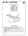
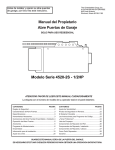
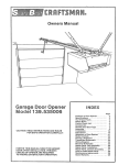
®
Owner's Manual
FOR RESIDENTIAL USE ONLY
®
Garage Door Opener
Model 139.18205SR - 1/2 HP
Model 139.18203SR - 1/3 HP
CAUTION! PLEASE READ THIS MANUAL CAREFULLY
The MODEL NUMBER label is located on the front panel of your opener.
CONTENTS
PAGE
Safety Rules..............................................................2
Features of Your Opener .........................................3
Specifications ...........................................................3
You'll Need Tools .....................................................3
Completed Installation Illustration .........................4
Operation of Your Opener .......................................5
Accessories ..............................................................5
Care & Maintenance of Your Opener......................6
Assembly Instructions.............................................7
Installation Instructions.........................................10
Travel Limit Adjustments ......................................20
CONTENTS
PAGE
Force Adjustments ...................................................21
Safety Reverse Test..................................................22
Setting/Changing Code ............................................23
Having a Problem? ...................................................24
Carton Contents & Hardware Illustrated ................26
Repair Parts, Rail Assembly ....................................26
Repair Parts, Installation..........................................26
Repair Parts, Chassis Assembly.............................27
How To Order Repair Parts......................................28
Warranty ....................................................................28
FASTEN THIS MANUAL NEAR THE GARAGE DOOR AFTER INSTALLATION.
PERIODIC CHECKS OF THE OPENER ARE REQUIRED TO INSURE SATISFACTORY OPERATION.
Start By Reading These Important Safety Rules
THESE SAFETY ALERT SYMBOLS MEAN CAUTION - PERSONAL SAFETY, PROPERTY DAMAGE OR
DANGER FROM ELECTRIC SHOCK. READ THESE INSTRUCTIONS CAREFULLY.
THIS GARAGE DOOR OPENER IS DESIGNED AND TESTED TO OFFER REASONABLY SAFE SERVICE
PROVIDED IT IS INSTALLED AND OPERATED IN STRICT ACCORDANCE WITH THE FOLLOWING SAFETY
INSTRUCTIONS.
FAILURE TO COMPLY WITH THE FOLLOWING INSTRUCTIONS MAY RESULT IN SERIOUS PERSONAL
INJURY OR PROPERTY DAMAGE.
CAUTION: IF YOUR GARAGE HAS NO SERVICE ENTRANCE DOOR, INSTALL MODEL 18752 EMERGENCY RELEASE
KEYLOCK. THIS ACCESSORY ALLOWS MANUAL OPERATION OF GARAGE DOOR FROM OUTSIDE IN CASE OF
POWER FAILURE.
KEEP GARAGE DOOR BALANCED. Sticking or
binding doors must be repaired. Garage doors,
door springs, cables, pulleys, brackets and their
hardware are under extreme tension and can
cause serious personal injury. DO NOT
ATTEMPT TO LOOSEN, MOVE OR ADJUST
THEM. Call for garage door service.
THE SAFETY REVERSE SYSTEM TEST IS
VERY IMPORTANT (page 22). Your garage door
MUST reverse on contact with a 1-inch obstacle
placed on the floor. Failure to properly adjust
the opener may result in serious personal injury
from a closing garage door. REPEAT THE TEST
ONCE A MONTH AND MAKE ANY NEEDED
ADJUSTMENTS.
DO NOT WEARE RINGS, WATCHES OR
LOOSE CLOTHING while installing or servicing
a garage door opener.
DO NOT USE THE FORCE ADJUSTMENTS
TO COMPENSATE FOR A BINDING OR
STICKING GARAGE DOOR. Excessive
force will interfere with the proper
operation of the safety reverse system or
damage the garage door (page 21).
To avoid serious personal injury from
entanglement, REMOVE ALL THE ROPES
CONNECTED TO GARAGE DOOR before
installing the garage door opener.
Install wall push button (or any additional push
buttons) IN A LOCATION WHERE GARAGE
DOOR IS VISIBLE, BUT OUT OF THE REACH OF
CHILDREN. DO NOT ALLOW CHILDREN TO
OPERATE PUSH BUTTON(S) OR TRANSMITTER. Serious personal injury from a closing
garage door may result from misuse of the
opener.
DISENGAGE ALL EXISTING GARAGE DOOR
LOCKS to avoid damage to garage door.
Installation and wiring must be in compliance
with your local building and electrical codes.
CONNECT THE POWER CORD ONLY TO A
PROPERLY GROUNDED OUTLET.
CAUTION: Activate opener only when the door
is in full view, free of obstructions and opener is
properly adjusted. NO ONE SHOULD ENTER
OR LEAVE THE GARAGE WHILE DOOR IS IN
MOTION. DO NOT ALLOW CHILDREN TO PLAY
NEAR THE DOOR.
Use the emergency release ONLY to disengage
the trolley and, if possible, ONLY when the door
is closed. DO NOT USE THE RED HANDLE TO
PULL DOOR OPEN OR CLOSED.
LIGHTWEIGHT DOORS OF FIBERGLASS,
ALUMINUM OR STEEL MUST BE SUBSTANTIALLY REINFORCED TO AVOID DOOR
DAMAGE. (See page 17.) The best solution is to
check with your garage door manufacturer for
an opener installation reinforcement kit.
DISCONNECT ELECTRIC POWER TO GARAGE
DOOR OPENER BEFORE MAKING REPAIRS
OR REMOVING COVERS.
Fasten a CAUTION LABEL to the wall, adjacent
to the Wall Push Button, and the other to the
garage door, as reminders of safe operating
procedures.
2
Before you begin, please check the contents of the cartons. Illustrations of parts and hardware are
shown on pages 26 and 27. Separate the hardware for assembly and installation as shown.
FEATURES OF YOUR OPENER
5. Automatic Reconnect: Trolley halves reconnect for
automatic operation when opener is activated after
an emergency disconnect.
6. Digital Radio Controls: Codes can be set and
changed easily and as often as you would like.
7. Easy Limit Adjustment: Limits of door opening and
closing adjusted by turning screws without removing
opener cover.
8. 3-Function Transmitter: Has three push buttons.
Each button can activate one or more Light Control
and/or garage door opener. The opener is factory
preset to activate with LARGE push button on
transmitter.
1. Opener Light: Turns on and off automatically with
4-1/2 minute illumination for your safety and
convenience.
2. Emergency Disconnect: Pull cord disconnect
permits manual door operation in case of an
emergency or power failure.
3. Motor: Permanently lubricated with automatic reset.
4. Safety System: Independent up and down force
adjustment. The door REVERSES automatically
when obstructed in DOWN direction. The door
STOPS when obstructed in UP direction.
SPECIFICATIONS
MOTOR
Type..................................Permanent split capacitor
Speed...............................1500 rpm
Volts..................................120 Volts AC - 60 Hz. Only
Current .............................4.5 amperes
DRIVE MECHANISM
Gears................................16:1 worm gear reduction
Drive .................................Chain & cable with two-piece trolley on
steel Tee rail
Length of travel ................Adjustable to 7-1/2 feet
Travel rate ........................6 to 8 inches per second
Lamp ................................On when door starts to travel, off 4-1/2
minutes after stop.
Door linkage.....................Adjustable door arm. Pull cord trolley
release.
SAFETY
Personal ..........................Push button and automatic reversal in
down direction. Push button and
automatic stop in UP direction
Electronic.........................Independent UP and DOWN force
adjustment screws
Electrical..........................Motor overload protector & low voltage
push button wiring
Limit device .....................Circuit actuated by limit nut
Limit adjustment..............Screwdriver adjustment on side panel
Start circuit ......................Low voltage push button or radio
control
DIMENSIONS
Length (overall) ...............124 inches
Headroom required.........2 inches
Hanging weight ...............32 pounds
YOU'LL NEED TOOLS
During assembly and installation of your opener, the instructions will call for the use of various hand
tools shown below.
1
Carpenter’s
Level
Pencil
2
Hack Saw
Tape Measure
Wire Cutters
Electric Drill
Claw Hammer
3/16" & 5/16" Drill Bits
Pliers
Screwdriver
Stepladder
Adjustable End Wrench
Socket Wrench
3
BEFORE YOU BEGIN, PLEASE TAKE SOME TIME TO CAREFULLY EXAMINE THE ILLUSTRATIONS OF AS
TYPICAL GARAGE DOOR OPENER INSTALLATION ON BOTH A SECTIONAL AND A ONE-PIECE DOOR.
Some installation instructions vary for sectional and one-piece doors. Follow only those instructions which apply
to your door type.
Do you have a finished ceiling in your garage? If so, you will need a support bracket and additional fastening
hardware. Refer to Step 4, Page 13 for specific requirements.
Do you have a lightweight or metal door (or does it have glass panels)? If so, horizontal and vertical
reinforcement is required. Refer to Step 8, Page 17.
Support Bracket
and Fastening
Hardware
(Not Supplied)
SECTIONAL
DOOR INSTALLATION
Header
Bracket
Cable Pulley
Bracket
Cable
Horizontal & Vertical
Support - Not Supplied
(Needed Only for
Lightweight Garage
Door Installation)
Trolley
Chain
Garage
Door
Spring
Horizontal
Garage Door
Reinforcement
(If needed)
Header
Garage
Door
Straight
Door
Arm
Emergency
Curve
Tolley
Door
Release
Arm
Door Bracket
& Plate
Vertical Garage Door
Reinforcement (if needed)
Finished
Ceiling
Support Bracket
and Fastening
Hardware
(Not Supplied)
ONE-PIECE DOOR INSTALLATION
Cable
Pulley Bracket
Cable
Trolley
Chain
Header
Bracket
Door Bracket
& Plate
Header
4
Garage
Door
Emergency
Trolley
Release
Straight
Door
Arm
Curve
Door
Arm
Operation of Your Opener
CAUTION
• DO NOT PERMIT CHILDREN TO PLAY IN THE
• BEFORE YOU PROCEED, PLEASE READ
AREA OF THE DOOR.
SAFETY RULES ON PAGE 2 AND THE
•
OPERATE
ONLY WHEN OPENER IS PROPERLY
OPERATING INSTRUCTIONS ON THIS PAGE
ADJUSTED AND THE DOOR IS VISIBLE AND
CAREFULLY.
UNOBSTRUCTED.
• TO AVOID DIFFICULTY DURING INSTALLATION,
DO NOT RUN OPENER UNTIL INSTRUCTED TO
DO SO.
OPENER LIGHT will turn on under the following
conditions: When the opener is initially plugged in;
when the power is interrupted; when the opener is
activated. Light turns off automatically after 4-1/2
minutes.
HOW DOOR MOVES WHEN OPENER ACTIVATES:
1. If open, door will close. If closed, the door will open.
2. If closing, the door will reverse.
3. If opening, the door will stop (allowing space for
entry and exit of pets and for fresh air).
4. If the door has been stopped in a partially open
position, it will close.
5. If obstructed while closing, the door will reverse.
6. If obstructed while opening, the door will stop.
TO ACTIVATE THE OPENER:
Use any of the following devices:
1. The 3-Function Transmitter. The LARGE push
button has been factory pre-set to activate the
garage door opener. Hold the LARGE push button
down until the door starts to move.
2. The Wall Push Button. Hold push button down until
the door starts to move.
3. Key Switch or Digital Entry System accessories.
HOW TO OPERATE THE DOOR MANUALLY:
DOOR SHOULD BE FULLY CLOSED IF POSSIBLE.
WEAK OR BROKEN SPRINGS COULD ALLOW AN
OPEN DOOR TO FALL RAPIDLY PROPERTY
DAMAGE OR SERIOUS PERSONAL INJURY
COULD RESULT. DO NOT USE EMERGENCY
HANDLE TO PULL DOOR OPEN OR CLOSED.
Disconnect door from opener by pulling down sharply
on red handle. Lift door manually. To automatically
reconnect door to opener, press Wall Push Button.
THE LOCKOUT FEATURE: Prevents trolley from
reconnecting automatically. If you need to use this
feature, pull emergency handle down and back (toward
the opener).Trolley will remain "Locked-Out" and door
can be raised and lowered manually. To reconnect
trolley, pull emergency handle straight down.
ACCESSORIES Sears offers many useful accessories for your garage door opener. They are
illustrated below with Sears stock numbers and descriptions.
18727
18725
18756
OUTDOOR KEY SWITCH:
Opens the garage door automatically
from outside with the turn of a key
when transmitter is not handy.
LIGHT CONTROL (Wire-In):
Controls interior or exterior
lights. Wires into electrical
box like a dimmer switch.
LIGHT CONTROL (Plug-In):
Controls interior lights. Plugs
into a wall receptacle.
18755/18776
DIGITAL ENTRY SYSTEMS:
Enables the homeowner to operate
garage door opener from outside by
entering code on specially designed
keypad.
18752
EMERGENCY RELEASE KEY LOCK:
REQUIRED for a garage with NO
service door.
Allows manual operation of garage door
from outside in case of power failure.
18754-8'
18753-10'
TEE RAIL EXTENSION KIT:
With a longer section of Tee rail & a
chain/cable assembly. to allow 8 foot
or 10 foot doors to open fully.
18778
18785
3-FUNCTION TRANSMITTER:
Standard size. With visor clip.
DOOR CLEARANCE BRACKETS:
(For Sectional Doors ONLY)
Replace top brackets and rollers on
door to reduce height of door travel.
For use when installing opener in
garage with low headroom clearance.
5
CARE OF THE OPENER
When properly installed, opener will provide high
performance with a minimum of maintenance. The
opener does not require additional lubrication.
CHAIN TENSION ADJUSTMENT: After installation of
the opener and adjustment of forces and limits, the
chain may appear loose. This is normal.
Most complaints of unsatisfactory opener operation can
be traced to problems with the door itself. When
operated manually, a properly balanced door will stay in
any point of travel while being supported entirely by its
springs.
TO CHECK THE CHAIN TENSION: Disconnect the
trolley by pulling the red emergency handle. If the chain
returns to the position described and illustrated in Step 4
page 9, DO NOT make ANY further adjustments.
TRANSMITTER: The 3-function transmitter will operate
more than one garage door opener, if desired. The push
buttons may also be used to operate other 18000SR
Series garage door openers and light products, Models
18727 and 18725. The standard transmitter may be
secured to car sun visor with clip provided. Additional
transmitters can be purchased at any time. Refer to
Accessories on page 5.
THE OPENER IS NOT INTENDED TO CORRECT
ANY PROBLEMS THAT ARE CAUSED BY AN
UNBALANCED OR BINDING DOOR, BROKEN
DOOR SPRINGS OR BY FAULTY DOOR
HARDWARE.
LIMIT AND FORCE ADJUSTMENTS: These
adjustments must be checked and properly set when
opener is installed. Only a screwdriver is required.
Pages 20 and 21 refer to the limit and force
adjustments. Follow the instructions carefully.
Any new transmitter must be set to the same code as
the original transmitter. Page 23 explains how to change
your existing code and use the transmitter(s) with the
other receivers mentioned above. Self service of your
radio controls is not recommended. If service is needed,
contact your nearest Sears Service Center.
REPEAT THE SAFETY REVERSE TEST AFTER ANY
ADJUSTMENT. Weather conditions may cause
some minor changes in the door operation,
requiring some readjustments, particularly during
the first year of operation.
TRANSMITTER BATTERY: The 12 Volt battery should
produce power for at least one year. As long as there is
adequate power, the transmitter battery test light will
glow when the push button is pressed (and the opener
or other control will operate). If light does not come on,
replace the battery. If transmission range lessens, check
the battery test light.
THE SAFETY REVERSE SYSTEM IS IMPORTANT
(SEE Pg. 22). GARAGE DOOR MUST REVERSE ON
CONTACT WITH A 1-INCH OBSTACLE PLACED ON
THE FLOOR. FAILURE TO PROPERLY ADJUST
OPENER MAY RESULT IN SERIOUS PERSONAL
INJURY FROM A CLOSING GARAGE DOOR.
TO CHANGE BATTERY: Slide the battery
compartment cover back. Remove old battery and
position and new 12 Volt battery as directed.
Back Panel
of Opener
Force
Adjustment
Control
RED
WHT
BLK
YEL
H
I
G
H
L
O
W
N
OR MA
UP
FORCE
L
H
I
G
H
L
O
W
N
OR MA
L
DOWN
FORCE
H
I
G
H
Limit Adjustment
Screws
L
O
W
N
OR MA
L
H
I
G
H
L
O
W
N
OR MA
INCREASE INCREASE
DOWN
UP
TRAVEL
TRAVEL
L
FCC ID: BY821635172G19
ASSEMBLED IN MEXICO
THIS DEVICE COMPLIES WITH FCC
RULES PART 15.Operation of this device
is subject tothe followingtwo conditions;
1. This device may not cause harmful
interference; 2. This device must accept
UP
FORCE
DOWN
FORCE
any harmful interference that may be
recieved, including interference that
may cause undesired operation.
Adjustment Label
Left Side Panel
Adjustment Label
MAINTENANCE OF YOUR OPENER
ONCE A MONTH
MANUALLY OPERATE DOOR. If it is unbalanced or
binding, call professional garage door service.
CHECK TO BE SURE DOOR OPENS & CLOSES
FULLY.
Adjusts Limits and/or Force if necessary.
REPEAT SAFETY REVERSE TEST. Make any
necessary adjustments (See Page 22).
TWICE A YEAR
CHECK CHAIN TENSION. Adjust if necessary.
ONCE A YEAR
OIL DOOR ROLLERS, BEARINGS AND HINGES.
6
CAUTION: Do not tighten the lock nuts until bolt
necks are seated in square holes and rail sections
are positioned correctly (see right and wrong
views below).
ASSEMBLY STEP 1
Assemble Tee Rail &
Attach Cable Pulley Bracket
TO AVOID INSTALLATION DIFFICULTIES, DO
NOT RUN THE GARAGE DOOR OPENER UNTIL
INSTRUCTED TO DO SO.
Step 1- Assemble T-Rail & Attach Chain Pulley Bracket
Liftmaster
PROCEDURE: Place the 3 Tee rail sections
on a flat 3750E (European/English)
surface for assembly. THIS IS IMPORTANT. The
end #1 (Yellow) - 8/27/90
Disk
RIGHT
sections are identical. THE CENTER SECTION
WRONG
BRACES MUST BE POSITIONED AGAINST THE
END SECTIONS AS SHOWN. Make sure that the
“directional arrow” is pointing toward the front (to
door). Study the illustration CAREFULLY.
(When assembled, Tee rail has a front-to-back
position as shown)
Bolt rail sections together with the hardware
illustrated and from the direction indicated.
SQUARE NECKS ON CARRIAGE BOLTS MUST
BE SEATED IN SQUARE HOLES IN RAIL
SECTIONS.
T-RAIL BACK
(TO CHASSIS)
T-Rail
(End Section)
1/4'' Lock Nut
Brace
Carriage Bolt
1/4"-20x1/2"
T-Rail
(Center Section)
The end sections of the rail
MUST be connected to the center
section from the direction shown
in the illustration. Otherwise, the
trolley will hit against the nut
when installed (Pg. 8)
OR
Brace
TO G
ARAG
E DO
Screws
5/16"-18x7/8"
Chain
Pulley
Bracket
st
T-Rail
(End Section)
Square Carriage
Bolt Holes
Screws
5/16"-18x7/8"
Lock Washer
5/16"
Chain
Pulley
Bracket
Chain pulley bracket
attaches to FRONT
END of t-rail
lel
ral
t&
Mu
B
ke
ac
Br
il
Ra
a
eP
Nut
5/16"
lel
ral
st
B
a
eP
Mu
Position the cable pulley bracket on theailfront
end of
R
&
Tee rail as shown. Fasten securely with
the
hardware
t
ke
ac
provided.
Br
IMPORTANT : When tightening screws, be sure to
Nut
Washer to rail. Otherwise,
keep bracketLock
parallel
rail may
5/16"
5/16"
bow when opener is operated.
T-RAIL FRONT
(TO DOOR)
7
ASSEMBLY STEP 2
Trolley
Install Trolley
TO
GA
R
AG
E
DO
OR
AS A TEMPORARY STOP, INSERT A
SCREWDRIVER INTO HOLE IN FRONT END OF
TEE RAIL.
Attach threaded shaft to trolley with lock washer and
nuts as shown.
Temporary Stop
Screwdriver
Inner Nut
5/16"
Lock Washer
5/16"
Outer Nut
5/16"
Threaded
Shaft
Trolley
Slide trolley assembly along rail to screwdriver stop.
NOTE: If trolley hits against nut on Tee rail, bolts
USE ONLY THIS
and nuts were attached from the wrong side and
TYPE AND SIZE
must
be repositioned. Review Step 1.
SCREW
Washered Screw
5/16"-18x1/2"
Hex Screw
5/16"-18x7/8"
Trolley
Stop Hole
Tee Rail
(Back Section)
ASSEMBLY STEP
3
Lock Washer
USE ONLY THOSE SCREWS
MOUNTED IN TOP OF OPENER.
FAILURE TO DO SO WILL CAUSE
SERIOUS DAMAGE TO OPENER.
5/16"-18
Fasten Tee Rail to opener
Nut
5/16"-18
Washered Screw
5/16"-18x1/2"
Hex Screw
5/16"-18x7/8"
PROCEDURE: Place the opener on packing
material to protect the cover. For convenience,
place a support under the cable pulley bracket.
Remove the (2) 5/16'-18x1/2" washered screws
mounted in the top of the opener. Align holes in
back end of Tee rail with holes in opener. Fasten the
rail with the (2) washered screws previously
removed and tighten securely.
CAUTION: USE ONLY THESE SCREWS. Use of
any other screws will cause serious damage to
door opener.
Insert a 5/16"-18x7/8" hex screw into trolley stop
hole in Tee rail as shown. Tighten securely with a
5/16" lock washer and nut.
Trolley
Stop Hole
Tee Rail
(Back Section)
Lock Washer
5/16"-18
Nut
5/16"-18
8
USE ONLY THIS
TYPE AND SIZE
SCREW
ASSEMBLY STEP 4
CAUTION: DO NOT REMOVE THE CHAIN/CABLE
FROM THE DISPENSER CARTON
Install Chain//cable &
Attach Sprocket Cover
Master Link
Clip-On Spring
Detach cable loop from carton and fasten to trolley
with a master link from coin envelope.
MASTER LINK PROCEDURE: Push pins of master
link bar through cable loop and hole in front end of
trolley (See Figure A,) Push cap over pins and into
notches until both pins are securely locked.
Caution: Keep the chain and cable taut during
installation to help prevent kinking..
Master Link
Clip-On Spring
Master
Link Cap
C
Flat End of
Threaded Shaft
Master
Link Cap
A
Chain
T-Rail
Cable
Loop
Pin Notch
Pin
Trolley
Install Chain and Cable
In This Direction
Master
Link
Cable
Pulley
B
Install Chain
In This Direction
Opener Chassis
Sprocket
With trolley against screwdriver, dispense cable
around pulley. Proceed back around opener sprocket
as shown in Figure B (be sure sprocket teeth engage
chain) and forward to threaded trolley shaft (See
Figure C.)
Use second master link to connect chain to flat end of
shaft. Check to make sure the chain is not
twisted.
REMOVE THE SCREWDRIVER.
Sprocket
Cover
Tab Slot
ATTACH SPROCKET COVER TO OPENER: Insert
back tab in opener slot. Bend cover forward and insert
front tab in slot on mounting plate.
Mounting
Plate
TIGHTEN CHAIN/CABLE
CAUTION: Keep the chain from twisting as nuts
are turned.
Thread inner nut on the trolley in the direction shown.
(loosen outer nut first if necessary.)
Tension is correct when chain is approximately 1/2"
above base of Tee rail. midway between cable pulley
bracket and opener. To maintain proper tension,
tighten outer nut as shown.
Sprocket noise can result if chain is either too
loose or too tight.
CAUTION: Do not overtighten chain. (See Page 6).
Tighten
Lock
Inner
Washer
Nut
Tighten
Outer
Nut
Trolley
Chain
1/2 Inch
Base of Tee Rail
9
BEFORE BEGINNING INSTALLATION OF GARAGE DOOR OPENER, BE SURE TO COMPLY WITH ALL
SAFETY RULES.
IT IS RECOMMENDED THAT THE OPENER BE INSTALLED 7 FEET OR MORE ABOVE FLOOR WHERE
SPACE PERMITS.
KEEP GARAGE DOOR BALANCED. STICKING OR BINDING DOORS MUST BE REPAIRED. THE GARAGE
DOOR, DOOR SPRINGS, CABLES, PULLEYS, BRACKETS AND THEIR HARDWARE ARE UNDER
EXTREME TENSION AND CAN CAUSE SERIOUS PERSONAL INJURY. DO NOT ATTEMPT TO LOOSEN,
MOVE OR ADJUST THEM. CALL FOR GARAGE DOOR SERVICE.
DO NOT WEAR WATCHES, RINGS OR LOOSE CLOTHING WHOLE INSTALLING OR SERVICING A DOOR
OPENER.
THE HEADER BRACKET MUST BE
RIGIDLY FASTENED TO HEADER
WALL. REINFORCE WALL WITH A
2x4 IF NECESSARY. FAILURE TO COMPLY
MAY RESULT IN IMPROPER OPERATION OF
SAFETY REVERSE SYSTEM (SEE PAGE 22).
INSTALLATION STEP 1
Position and Install Header Bracket
Installation procedures vary according to
garage door types. Follow the instructions
which apply to your door.
SECTIONAL DOOR & 1-PIECE DOOR WITH TRACK
1. Close door and mark the inside vertical centerline
of garage door.
Extend the line onto header wall above door.
2. Open door to highest point of travel as shown. Draw
an intersecting horizontal line on header wall 2"
above high point. This height will provide travel
clearance for top edge of door.
NOTE: When the headroom is not sufficient for 2"
clearance, bottom edge of bracket may be
positioned parallel to high point of travel.
Door Clearance Brackets are designed for low
headroom installations (page 5). They replace top
brackets and rollers on the garage door, thereby
lowering the high point of door travel. Installation
instructions are contained in the accessory carton.
Ceiling
Header
Bracket
Track
Highest Point
of Travel
Header
Bracket
Highest Point
of Travel
Door
Track
Door
SECTIONAL DOOR
CURVED TRACK
ONE-PIECE DOOR
HORIZONTAL TRACK
JAMB HARDWARE
Jamb
Hardware
Header
Bracket
3. Position bracket as shown (centered on vertical
guideline with bottom edge of bracket on horizontal
line).
Mark either top and bottom or left and right bracket
holes. Drill 3/16" pilot holes and fasten bracket.
Lag Screws
5/16"x18x1-7/8"
2"
Highest
Point of
Travel
Proceed to Step 2, Page 11.
10
ONE-PIECE DOOR WITHOUT TRACK
PLEASE READ AND COMPLY WITH THE WARNINGS ON PAGE 10. THEY APPLY TO THE INSTALLATION
OF THE HEADER BRACKET REGARDLESS OF DOOR TYPE.
EXAMPLE
Distance from top of door
(at highest point of travel) to floor ...........................92"
Actual height of door...........................................– 88"
1. Close door and mark inside vertical centerline of
garage door. Extend line onto header wall above
door.
2. Open door to highest point of travel as shown.
Measure the distance from top of door to floor.
Subtract actual height of door. Add 8' to remainder
(See Example)
NOTE: If the total number of inches exceeds
height available in garage, use the maximum
height possible. On finished ceilings, do not
position the bracket closer than 1/2" from ceiling.
Remainder.................................................................4"
Add........................................................................+ 8"
Bracket height on header wall ............................= 12"
(Measure UP from top of CLOSED door.)
POSITION AND FASTEN HEADER BRACKET AS
DESCRIBED AND SHOWN IN NO. 3 ON PAGE 10.
Header
Bracket
Header
Bracket
Highest Point
of Travel
Highest Point
of Travel
Distance
Door
Distance
Door
Jamb
Hardware
Pivot
ONE PIECE DOOR
NO TRACK
JAMB HARDWARE
ONE PIECE DOOR
NO TRACK
PIVOT HARDWARE
INSTALLATION STEP 2
Attach Tee Rail to Header Bracket
(All Door Types)
Header
Bracket
Clevis Pin
5/16"x2-3/4 "
PROCEDURE: Position opener on garage floor below
header bracket. Use packing material as a protective
base.
Ring
Fastener
NOTE: To enable Tee rail to clear sectional door
springs, it may be necessary to lift opener onto a
temporary support.
CAUTION: The opener must either be secured to a
support or held firmly in place by another person.
Cable
Pulley
Bracket
Raise Tee rail until pulley and header brackets come
together. Align bracket holes and join with clevis pin as
shown. Insert ring fastener to secure.
Packing
Material
11
TO PREVENT DAMAGE TO ALL
LIGHT-WEIGHT DOORS AND DOORS
WITH WINDOWS, DO NOT REST THE
OPENER ON THE DOOR.
INSTALLATION STEP 3
Position the Opener
Follow instructions which apply to your door
type as illustrated.
INSTALLATION — SECTION DOOR & 1-PIECE DOOR WITH TRACK
NOTE: A 2x4 is convenient for setting an idea
door-to Tee rail distance. It is not necessary when
headroom is insufficient.
PROCEDURE: Raise the opener onto a stepladder.
Open garage door. Place a 2x4 on the top section of
door near centerline as shown. Rest Tee rail on 2x4 as
shown.
Tee Rail
2x4
Door
Stepladder
INSTALLATION – 1-PIECE DOOR WITHOUT TRACK
PROCEDURE: Measure the distance from floor to
top of door (in fully open position and parallel to the
floor). Using a stepladder as a support, raise opener
to the same distance from the floor (it will have a
slight angle as shown).
The top of the door should be level with the top of
opener. For maximum efficiency, do not position
opener more than 2 inches above this point.
Header
Bracket
Top of Opener
Equal
Distance
from
Floor
12
INSTALLATION STEP 4
Hang the Opener
THE OPENER MUST BE SECURELY FASTENED TO A STRUCTURAL SUPPORT OF THE GARAGE.
Three representative installations are shown. Yours may be different. Hanging brackets should be angled
(Fig1) or crossed (Fig. 2) to provide rigid support. On finished ceilings (Fig. 3). attach a sturdy metal bracket (not
supplied) to ceilings joists before installing opener.
PROCEDURE: Measure the distance from EACH
side of the opener to structural support.
Cut both pieces of the hanging bracket to required
lengths. Flatten one end of each bracket and bend or
twist to fit the fastening angles. Do not bend at the
brackets holes. Drill 3/16" pilot holes in the structural
supports. Attach flattened ends of brackets to
supports with 5/16"x1-7/8" lag screws.
Lift opener and fasten to hanging bracket as shown.
Check to make sure Tee-rail is centered over door.
REMOVE 2x4. Operate door manually. If door hits
the rail, raise header bracket.
FIGURE 2
5/16"-18x7/8" Screw
5/16" Lock Washer
5/16"-18 Nut
Grease the top and underside of rail surface
on which trolley slides. A tube of grease is
supplied.
Bracket
(Not Supplied)
FIGURE 1
FIGURE 3
FINISHED
CEILING
Lag Screws
5/16"x1-7/8"
(Not Supplied)
5/16"-18x7/8" Screw
5/16" Lock Washer
5/16"-18 Nut
Lag Screws
5/16"x1-7/8"
Measure
Distance
13
LOCATE WALL PUSH BUTTON (OR ANY ADDITIONAL PUSH BUTTONS) WHERE THE GARAGE DOOR IS
VISIBLE, AWAY FROM DOOR AND DOOR HARDWARE AND OUT OF THE REACH OF CHILDREN.
SERIOUS PERSONAL INJURY FROM A MOVING GARAGE DOOR MAY RESULT FROM MISUSE OF OPENER.
DO NOT ALLOW CHILDREN TO OPERATE WALL PUSH BUTTON(S) OR REMOTE CONTROL TRANSMITTER.
FASTEN THE CAUTION LABEL ON THE WALL NEAR WALL PUSH BUTTON AS A REMINDER OF SAFE OPERATING
PROCEDURES.
INSTALLATION STEP 5
Install Wall Push Button
Remove about 1/4" of insulation from each end of 2strand bell wire. Connect one end to the screw
terminals on back of Wall Push Button (or doorbelltype push button) as shown. NO POLARITY IS
REQUIRED.
Fasten the Wall Push Button with 6ABx1" sheet
metal screws. The doorbell-type push button has
6ABx1-1/2" sheet metal screws. Use anchors if
attaching to dry wall. Install on an inside garage wall.
A convenient place is alongside the service door and
OUT OF THE REACH OF CHILDREN.
Run bell wire up the wall and across the ceiling to the
opener. Secure with insulated staples.
Receiver terminals and antenna are located on back
panel of opener. Position antenna wire as shown.
Then connect the wire by color to the white and red
opener terminal screws.
DOOR BELL-TYPE
LIGHTED PUSH BUTTON
WALL PUSH BUTTON
Top Installation
Flange
Terminal Screws
WHT
RED
2-Strand
Bell Wire
RED
WHT.
Terminal Screws
Bottom Installation
Flange
Staples
RED
WHT
BLK
H
I
G
H
L
O
W
N
OR MA
UP
FORCE
Opener
Terminal
Screws
Lighted
Pushbutton
Rear Panel
of Opener
OPERATION OF THE WALL PUSH BUTTON
Press to open or close door.
Press again to REVERSE door during the CLOSING
cycle or to STOP door during OPENING cycle.
L
H
I
G
H
L
O
W
N
OR MA
L
DOWN
FORCE
243532tv 2243436
1376335361817353
askjhdoc lkjhoi `hoic
zjh zjh cc aiu ickck c
xzckjckuc czkzxkkcc
kkjhzxkjhzckyc . jh c
zjhxckjc cliyvn ckjc
zlh lkchy l cagv
,vbcjdu dkcid sac ccxb
Antenna
WIRING INSTRUCTIONS FOR ACCESSORIES
Outdoor Key Switch:
To red and white opener terminals
14
INSTALLATION STEP 6
Install Light and Lens:
Install a 75 watt maximum light bulb in socket. Light
will turn ON and ramain lit for 4-1/2 minutes when
power is connected. Then light will turn OFF.
If bulb burns out prematurely due to vibration,
replace with "Garage Door Opener' bulb.
INSTALL LENS: Slide lens into guides as shown.
Snap bottom tabs into lens slots. For convenience,
lens may be installed after adjustment Step 3 on
Page 22.
Light Lens
Lens Guide
Lens Slot
Lens Tab
USE EMERGENCY RELEASE ROPE
ONLY TO DISENGAGE TROLLEY.
DO NOT USE ROPE AND HANDLE
TO PULL DOOR OPEN OR CLOSED.
INSTALLATION STEP 7
Attach Emergency Release
Rope & Handle
PROCEDURE: Thread one end of rope through hole
in top of red handle so "NOTICE' reads right side up
as shown. Secure with an overhand knot.
NOTE: Knot should be at least 1" from the end of the
rope to prevent slipping.
Thread other end of rope through hole in release arm
of outer trolley. Adjust rope length so that handle is 6
feet above the floor. Secure with an overhand knot as
above.
NOTE: If it is necessary to cut rope, heat seal cut end
with a match or lighter to prevent fraying and/or
raveling.
Overhand
Knot
Trolley
Trolley
Release Arm
Rope
NOT
ICE
Overhand
Knot
75 Watt Max.
Light Bulb
Emergency
Release Handle
15
TO AVOID SERIOUS PERSONAL INJURY
FROM ENTANGLEMENT, REMOVE ALL
ROPES CONNECTED TO THE GARAGE
DOOR BEFORE OPERATING OPENER.
TO AVOID DAMAGE TO GARAGE DOOR AND
OPENER, MAKE DOOR LOCKS INOPERATIVE
BEFORE CONNECTING ELECTRIC POWER. USE A
WOOD SCREW OR NAIL TO HOLD THE LOCKS IN
“OPEN” (UNLOCKED) POSITION.
INSTALLATION AND WIRING MUST BE IN
COMPLIANCE WITH LOCAL ELECTRICAL AND
BUILDING CODES.
OPERATING AT OTHER THAN 120V 60Hz WILL
CAUSE OPENER MALFUNCTION AND DAMAGE.
INSTALLATION STEP 8
Connect Electric Power
RIGHT
WRONG
Opener MUST be permanently wired or plugged into
a grounded 3-prong receptacle wired according to
local electrical codes. DO NOT use a 2-wired
adapter. DO NOT USE an extension cord.
PROCEDURE FOR PERMANENT WIRING (if required by local codes)
PERMANENT WIRING
CONNECTION
DISCONNECT THE POWER AT THE
FUSE BOX BEFORE PROCEEDING.
Refer to illustration. Make connection through the
7/8" diameter hole in top of opener.
1.Remove opener cover screws and set cover aside.
2.Remove attached 3-prong cord.
3.Connect black (line) wire to black wire on terminal
block; white (neutral) wire to white terminal wire;
green (ground) wire to green ground screw.
Ground Tab
Green Ground
Screw
Green Wire
(Ground)
CAUTION: BE SURE THAT THE UNIT IS
GROUNDED ACCORDING TO LOCAL CODE.
Black
Wire
IMPORTANT NOTE: TO AVOID INSTALLATION
DIFFICULTIES, DO NOT RUN OPENER NOW.
White
Wire
16
TO PREVENT DAMAGE TO LIGHTWEIGHT
AND METAL GARAGE DOORS (OR ONES
WITH GLASS PANELS), ALWAYS REINFORCE THE INSIDE OF DOOR —BOOTH
VERTICALLY AND HORIZONTALLY—WITH
2x4 BOARDS OR ANGLE IRON.
INSTALLATION STEP 8
Fasten Door Bracket and Plate
Follow instructions which apply to your door
type as illustrated below.
The horizontal brace should be at least 6 feet long. The vertical brace should cover height of top panel. The best
solution is to check with your garage door manufacturer for a door reinforcement kit for an opener installation.
Sectional Door Installation Procedure
Assemble door bracket and plate as shown. Center
bracket on previously marked vertical guideline (or up
to one foot left or right of center if necessary).
Position the bracket assembly on the face of the door
within the following limits:
A) The top edge of the bracket 2"-4" below top edge
of door.
B) Directly below any structural support across top
of door.
Placement depends on your particular needs.
Mark and drill 5/16" TOP and BOTTOM fastening
holes. Secure bracket as shown.
SECTIONAL DOOR
Header
Bracket
Vertical
Center
Line
Door Bracket &
Plate Assy.
Top of Door
Door
Bracket
Reinforcement
Board for
Lightweight Doors
Door Bracket
Plate
Nut
5/16"-18
Carriage Bolt
5/16"-18x2-1/2"
Inside Edge
of Door or
Reinforcement Board
Lock Washer
5/16"
All One-Piece Door Installation Procedure
NOTE: Door bracket has left and right side
fastening holes. Assemble and install the door
bracket and plate if your installation requires top
and bottom fastening holes.
Center bracket (with or without plate as required) at
the top of the inside face of door as shown. Mark
holes.
Drill 5/16" holes and fasten the door bracket with
hardware supplied.
ONE PIECE DOOR
Header
Bracket
Header Wall
Door
Bracket
Door
Bracket
Plate
Carriage Bolt
5/16"-18x1/2"
Door
Bracket
Nut
5/16"-18
Top Edge
of Door
(Inside)
Vertical
Center
Line
Lock Washer
5/16"
17
Door Bracket
Plate
INSTALLATION STEP 10
Connect Door Arm to Trolley
Follow only those instructions which apply to
your door type.
SECTIONAL DOORS ONLY
Make sure garage door is closed tight. Pull the emergency release handle to disconnect the trolley.
Manually move outer trolley back to the center of inner trolley as shown in figures A, B and C.
FIG. A: Fasten straight door arm section to outer
trolley with a clevis pin. Secure the connection with a
ring fastener.
Fasten curved section to the door bracket in the
same way.
A
FIG. B: Bring arm sections together. Find two pairs of
holes that line up and join sections.
Select holes as far apart as possible to increase door
arm rigidity.
B
B
Clevis
Pin
Ring
Fastener
C
Lock
Washers
5/16"
Rope
Emergency
Release
Handle
Nuts
5/16"-18
Door
Bracket
Clevis Pin
Straight
Door Arm
Screws
5/16"-18x7/8"
Curved
Door Arm
Door
Bracket
FIG. C: If holes in curved arm are ABOVE holes in
straight arm, disconnect straight arm. Cut about 6"
from the solid end. Reconnect to trolley with CUT
END DOWN as shown.
Bring arm sections together. Find two pairs of holes
that line up and join with screws, lock washers and
nuts.
C
gency
ease
ndle
Lock
Door
Washers
Bracket
5/16"
Rin
Fast
Nuts
5/16"-18
Clevis Pin
Straight
Door Arm
Screws
Screws
5/16"-18x7/8"5/16"-18x7
Cut This End
Fully Closed
Trolley when opener is operated
Proceed to Step 1, page 20. Trolley will re-engage automatically
18
ALL ONE-PIECE DOORS
ASSEMBLE DOOR ARM: Fasten straight and
curved door arm sections together to their longest
possible. With door closed, connect straight door arm
section to door bracket with a clevis pin. Secure with
a ring fastener.
Door
Bracket
Clevis Pin
Ring
Fastener
Lock
Washers
5/16"
Straight
Door Arm
Nuts
5/16"-18
Curved
Door Arm
Screws
5/16"-18x7/8"
Before connecting door arm to trolley, limits of travel must be adjusted on one-piece doors. Limit adjustment
screws are located on left side panel as shown in illustration on page 20. Follow procedures below.
Fully Closed
Trolley
Fully Open
Trolley
Door Arm
Bracket
Closed
Door
Door Arm
Door Arm
Connector Hole
Open Door
Door Arm Bracket
Door Arm
Connector Hole
Door Arm
ADJUSTMENT PROCEDURES
OPEN DOOR ADJUSTMENT
Decrease UP limit. Turn UP limit adjustment screw
counterclockwise 4 complete turns.
Press Wall Push Button. Trolley will travel to full open
position.
Manually raise door arm to open position (parallel to
floor) and lift door arm to trolley. The arm should
touch trolley just in back of door arm connector hole
as shown in solid line drawing. If arm does not
extend far enough, adjust limit further. One full turn
equals 2" of door travel.
CLOSED DOOR ADJUSTMENT
Decrease DOWN limit. Turn DOWN limit adjustment
screw clockwise 8 complete turns.
Press Wall Push Button. Trolley will travel to full
closed position.
Manually close door and lift door arm to trolley. The
arm should touch trolley just ahead of door arm
connector hole as shown in dotted line drawing. If
arm is behind the connector hole, adjust limit further.
One full turn equals 2" of door travel.
CONNECT DOOR ARM TO TROLLEY: With door closed, join curved arm to connector hole in trolley with
remaining clevis pin. Secure with ring fastener. NOTE: It may be necessary to lift door slightly to make
connection.
Run opener through a complete travel cycle. If door has a slight ‘backward’ slant in full open position, decrease
UP limits until door is parallel to floor.
19
ADJUSTMENT STEP 1
Adjust UP and DOWN Limits
Limit Adjustment
Screws
LIMIT ADJUSTMENT settings regulate the points at
which the door will stop when moving up or down.
IN
NOTE: Door STOPS in the UP direction if
anything interferes with door travel. Door
REVERSES in the DOWN direction if anything
interferes with the door travel (including binding
or unbalanced doors)
Left Side Panel
PROCEDURE: To operate the opener, press the
Wall Push Button or transmitter. Run the opener
through a COMPLETE TRAVEL CYCLE. No limit
adjustments are necessary when the door opens and
closes completely and doesn’t reverse unintentionally
when fully closed.
A
INCREASE INCREASE
DOWN
UP
TRAVEL
TRAVEL
Adjustment Label
The following chart outlines adjustments procedures. Run the opener through a COMPLETE TRAVEL
CYCLE AFTER AFTER EACH ADJUSTMENT.
NOTE: REPEATED OPERATION OF THE OPENER DURING ADJUSTMENT PROCEDURES MAY CAUSE
MOTOR TO OVERHEAT AND SHUT OFF. SIMPLY WAIT 15 MINUTES AND TRY AGAIN.
Read the chart carefully before proceeding to step 2. Use a screwdriver to make limit adjustments.
LIMIT ADJUSTMENT CHART
IF DOOR DOES NOT OPEN COMPLETELY
BUT OPENS AT LEAST FIVE FEET
Increase UP travel. Turn the UP LIMIT adjustment
screw clockwise. One turn equals 2" of travel.
IF OPENER REVERSES IN FULLY
CLOSED POSITION.
Decrease DOWN travel. Turn down limit adjustment
screw clockwise. One turn equals 2 inches of travel.
If door does not open at least 5 feet: Adjust UP
(OPEN) FORCE as explained in step 2.
IF DOOR REVERSES WHEN CLOSING AND
THERE IS NO INTERFERENCE TO TRAVEL
CYCLE
IF DOOR DOES NOT CLOSE COMPLETELY
INCREASE down TRAVEL. Turn down limit
adjustment screw counterclockwise. One turn equals
2" of travel.
Test door for binding: Pull emergency release handle.
Manually open and close door. If door is binding, call
for garage door service. If door is not binding or
unbalanced, adjust DOWN (CLOSE) FORCE. See
Step2.
If the door still will not close completely, the header
bracket is positioned too high. See Step 1, page 10.
20
DO NOT USE FORCE ADJUSTMENTS
TO COMPENSATE FOR A BINDING OR
STICKING
GARAGE
DOOR.
EXCESSIVE FORCE WILL INTERFERE WITH
PROPER OPERATION OF SAFETY REVERSE
SYSTEM OR DAMAGE GARAGE DOOR.
ADJUSTMENT STEP 2
Adjust Force
Force Adjustment Controls are located on rear panel
of opener. FORCE ADJUSTMENT settings regulate
amount of the power required to open and close
door.
NOTE: The door STOPS in the UP direction if
anything interferes with its travel. Door
REVERSED in the DOWN direction if anything
interferes with its travel (including binding or
unbalanced doors).
If the force adjustments are set too light, door travel
may be interrupted by nuisances reversals in DOWN
direction and stops in UP direction. Weather
conditions can affect the door movement, so
occasional adjustment may be needed.
Maximum force adjustment range is 260 degrees,
about 3/4 of a complete turn. Do not force controls
beyond that point. Turn force adjustment controls with
a screwdriver.
H
I
G
H
L
O
W
N
OR MA
UP
FORCE
L
H
I
G
H
Back Panel
of Opener
Force
Adjustment
Control
RED
WHT
BLK
YEL
H
I
G
H
L
O
W
N
OR MA
UP
FORCE
L
H
I
G
H
L
O
W
N
OR MA
L
DOWN
FORCE
H
I
G
H
L
O
W
N
OR MA
L
FCC ID: BY821635172G19
ASSEMBLED IN MEXICO
THIS DEVICE COMPLIES WITH FCC
RULES PART 15.Operation of this device
is subject tothe followingtwo conditions;
1. This device may not cause harmful
interference; 2. This device must accept
UP
FORCE
any harmful interference that may be
recieved, including interference that
may cause undesired operation.
Adjustmen
L
O
W
N
OR MA
L
DOWN
FORCE
Adjustment Label
FORCE ADJUSTMENT CHART
TEST DOWN (CLOSE) FORCE
Grasp the door handle or door bottom when door is
about halfway through DOWN (CLOSE) TRAVEL.
Door should reverse. If the door is hard to hold or
doesn’t reverse, decrease DOWN(CLOSE) FORCE
by turning the control in a counterclockwise direction.
Make 10 degree turn adjustments until door reverses
normally. After each adjustment, run opener through
a complete cycle.
IF DOOR DOESN’T OPEN AT LEAST 5 FEET
Increase UP (OPEN) FORCE by turning the control in
a clockwise direction. Make 10 degree turn
adjustments until door opens completely. Readjust
UP LIMIT if necessary. After adjustment, run opener
through a complete travel cycle.
IF DOOR REVERSES DURING DOWN
(CLOSE) CYCLE
Increase DOWN (CLOSE) FORCE by turning control
clockwise. Make 10 degree turn adjustments until
door completes close cycle. After each adjustment,
run the opener through a complete travel cycle.
PROCEED TO STEP 3
21
THE SAFETY REVERSE SYSTEM TEST
IS IMPORTANT. GARAGE DOOR MUST
REVERSE ON CONTACT WITH ONEINCH OBSTACLE PLACED ON THE FLOOR.
FAILURE TO PROPERLY ADJUST OPENER MAY
RESULT IN SERIOUS PERSONAL INJURY FROM
A CLOSING GARAGE DOOR. REPEAT TEST
ONCE A MONTH AND ADJUST AS NEEDED.
ADJUSTMENT STEP 3
Test Safety Reverse System
PROCEDURE: Place a one-inch obstacle on the
floor under the garage door. Operate door in DOWN
direction. The door MUST reverse on the obstruction.
If the door STOPS on the obstruction, it is not
traveling far enough in the DOWN direction. Increase
the DOWN limit by turning DOWN limit adjustment
screw counterclockwise 1/4 turn. REPEAT TEST.
NOTE: Make sure limit adjustments do not force
the door arm beyond a straight up and down
position. See the illustration on Page 18.
When the door reverses on the one-inch obstacle,
remove the obstruction and run the opener through 3
or 4 complete travel cycles to test the adjustment.
Door MUST NOT reverse in closed position. Repeat
Adjustment Steps 1, 2 and 3 if necessary.
SECTIONAL DOOR
ONE-PIECE DOOR
1 Inch Obstruction
1 Inch Obstruction
REPEAT ADJUSTMENT STEP 3 AFTER:
• EACH ADJUSTMENT OF DOOR ARM LENGTH, CLOSE FORCE OR DOWN LIMIT.
• ANY REPAIR OR ADJUSTMENT OF GARAGE DOOR (INCLUDING SPRINGS AND
HARDWARE)
• ANY REPAIR OR BUCKLING OF THE GARAGE FLOOR.
• ANY REPAIR OR ADJUSTMENT OF THE GARAGE DOOR OPENER.
22
ACTIVATE THE OPENER ONLY WHEN DOOR
IS FULL VIEW, FREE OF OBSTRUCTION
AND PROPERLY ADJUSTED. NO ONE
SHOULD ENTER OR LEAVE GARAGE WHILE DOOR IS
IN MOTION. DO NOT ALLOW CHILDREN TO OPERATE
REMOTES OR WALL PUSH BUTTONS. DO NOT
ALLOW CHILDREN TO PLAY NEAR THE DOOR.
Radio Controls
D.O.C. rules prohibit adjustments to or modification
of receiver and transmitter circuitry except for
changing the code setting and replacing the
transmitter battery. THERE ARE NO OTHER
USER SERVICEABLE PARTS.
Manufactured under 1 or more of the following U.S. patents: RE29,525; 4,037,201;
4,750,118; 4,806,930.
Your garage door opener (with RECEIVER ‘SR’ CODE BUTTON) has been factory set to operate with the
LARGE push button on the transmitter. The 3-function transmitter(s) can also activate additional garage door
openers and Models 18725 and 18727 light products.
Instruction are given below for matching the code in Model 18778 transmitters, changing your code selection
or using the transmitter(s) with other receivers.
MATCH/CHANGE THE CODE IN TRANSMITTER(S)
Code Switches (1-9)
1 2 3 4 5 6 7 8 9
0
+
0
Match
Code Switches
(2-9)
+
1 2 3 4 5 6 7 8 9
SET CODE SWITCHES IN ALL TRANSMITTERS TO MATCHING POSITIONS
Locate the code switches in transmitter(s) by sliding battery compartment cover back.
With a pen or screwdriver, change the setting of one or more switch (to a (+), (-) or (0) position).
NOTE: Code switches 2 through 9 in ALL transmitters used to operate a receiver must be set to match.
(Code switch 1 on a 3-function transmitter is neutral. Set of to ANY position. It will not affect the code
selected).
3-Function Transmitters - Model 139.18778
Code Switches (1-9)
SET RECEIVER TO MATCH TRANSMITTER(S) CODE
Garage Door Openers
Light Control Products (Models 18725 & 18727)
(Illustration B shows representative code switches)
(with receiver code button)
(Illustration A shows a garage door opener receiver)
3 FUNCTION
TRANSMITTER
Select a transmitter push
button to operate receiver
A
GARAGE DOOR
OPENER RECEIVER
(With SR Code Button)
RED
WHT
BLK
Push Button (-)
Push Button (+)
YEL
H
I
G
H
L
O
W
N
OR MA
UP
FORCE
L
H
I
G
H
B
Select a transmitter
push button to operate
receiver
L
O
W
N
OR MA
3 FUNCTION
TRANSMITTER
L
Push Button (0)
DOWN
FORCE
Indicator
SR
Code Button Light
1.Press the RECEIVER SR code button on the back panel of
opener (Illustration A.) The indicator light will turn ON.
2.STAND AWAY FROM THE DOOR and press the selected
push button on the transmitter.
CAUTION: Door will begin to move immediately if any
transmitter has been activated
If this occurs, wait until the door has completed its UP
or DOWN cycle. Then begin again at step 1.
This indicator light will turn OFF and door will move.
Receiver and transmitter codes now match and the opener
will operate with the selected push button on the transmitter.
NOTE: If transmitter push button is not pressed within
30 seconds, the indicator light will turn OFF. Begin
again at Step 1.
TO USE THE TRANSMITTER(S) WITH OTHER ‘SR’
CODE BUTTON RECEIVERS: Select another transmitter
push button to operate an additional garage door opener.
Make sure all transmitters used to operate receiver are set
to the same code. Repeat Steps 1 and 2.
23
Receiver Code Switches
+
1 2 3 4 5 6 7 8 9
0
With code switch #1 set
in the (-) position, receiver
will operate with transmitters'
large push button
LIGHT CONTROL PRODUCTS
(With Receiver Code Switches)
Slide receiver code
switch #1 to position
that matches selected
transmitter push button
(+, 0 or -)
Make sure all transmitters are set to matching code switch
positions as described above.
1. Select a transmitter push button to operate the receiver as
shown in Figure B
2. Locate receiver code switches. Set code switch #1 to
match transmitter (+), (-) or (0). Refer to illustration (B)
3. Hold a transmitter (with code switches visible) alongside
the receiver. Beginning with RECEIVER code switch #2,
match the position of each transmitter switch.
Having a Problem?
Review Pages 2 and 3 Before Proceeding
SITUATION
PROBABLE CAUSE & SOLUTION
OPENER DOESN'T OPERATE
FROM WALL PUSH BUTTON
OR TRANSMITTER
1. Have you disengaged all door locks? Review Step 8, page 16.
2. Does the opener have electric power? Plug a lamp into the outlet. If it doesn't light,
check fuse box or circuit breaker. (Some outlets are controlled by a wall switch.)
3. Repeated operation may have tripped the overload protector in the motor. Wait 15
minutes. Try again.
4. Is there a build-up of ice or snow under door? Door may be frozen to ground.
Remove any obstruction.
5. Remove bell wire from opener terminals. Short red and white terminals by touching
both terminals at same time with a piece of metal (screwdriver or coin). If opener
runs, check for a faulty wire connection at Wall Push Button or a short under staples.
OPENER OPERATES FROM
TRANSMITTER BUT NOT FROM
WALL PUSH BUTTON
1. Is Wall Push Button lit? If not, refer to No. 5 above.
DOOR OPERATES FROM WALL
PUSH BUTTON BUT NOT
FROM THE TRANSMITTER
1. Does the battery test light glow when transmitter push button is pressed? If not,
replace the battery.
2. Are wiring connections correct? Review Step 5, page 14.
2. If you have two transmitters and only one operates, review the code setting
procedures on page 23. ALL transmitters must be set to same code.
3. Is transmitter(s) operating any other remote control devices? See the code setting
prcedures on page 23.
4. Did you press the transmitter button designated to operate garage door opener?
TRANSMITTER HAS
SHORT RANGE
1. Check battery test light. If the light is dim, change the battery.
2. Change the location of the transmitter in the car.
3. A metal garage door, foil-backed insulation or metal siding will reduce the
transmission range. An antenna extender kit is available from any Sears store or
service center.
4. Check to be sure antenna on the rear panel of opener extends fully downward.
THE GARAGE DOOR OPENS
AND CLOSES BY ITSELF
1. Is there a neighbor with a garage door opener using the same frequency code?
Change your code. Review page 23.
2. Make sure that none of the transmitter push buttons is stuck in the "down" position.
3. Remove bell wire from opener terminals and operate from transmitter only. If this
solves the problem, the Wall Push Button is faulty (replace), or there is a short or
broken wire between Wall Push Button and opener.
DOOR DOESN'T OPEN
COMPLETELY
1. Is something obstructing the door?
2. If door opens at least 5 feet, travel limits may need to be increased. One turn equals
2 inches of travel. See page 20.
REPEAT SAFETY REVERSE TEST after the adjustment is complete.
3. If door has been working properly but now doesn't open all the way, increase the
UP FORCE. See page 21.
REPEAT SAFETY REVERSE TEST after the adjustment is complete.
DOOR DOESN'T CLOSE
COMPLETELY
1. Is something obstructing the door?
2. Review the Travel Limits Adjustment Chart on page 20.
REPEAT SAFETY REVERSE TEST after any adjustment of door arm length,
close force or down limit.
24
Having a Problem?
(Continued)
SITUATION
PROBABLE CAUSE & SOLUTION
DOOR REVERSES FOR NO
APPARENT REASON
1. Is something obstructing the door? Pull red emergency release handle. Operate
door manually. If it is unbalanced or binding, call for professional garage door
service.
2. Clear any ice or snow from garage floor area where garage door closes.
3. Review the Force Adjustment Chart on page 21.
REPEAT SAFETY REVERSE TEST after adjustment is complete.
4. If door reverses in FULLY CLOSED position, decrease travel limits (Page 20).
REPEAT SAFETY REVERSE TEST after the adjustment is complete. THE
NEED FOR OCCASIONAL ADJUSTMENT OF THE FORCE AND LIMIT
SETTINGS IS NORMAL. WEATHER CONDITIONS IN PARTICULAR CAN
AFFECT DOOR TRAVEL.
OPENER LIGHT
DOES NOT TURN ON
1. Replace the light bulb (75 watts maximum). Use a "garage door opener bulb" if
standard bulb burns out prematurely due to vibration. Vibration may be caused
by loose end panel. Retighten screws.
DOES NOT TURN OFF
1. There may be a defective ground at ceiling or wall receptacle.
UNIT MUST BE GROUNDED.
OPENER STRAINS OR MAXIMUM
FORCE IS NEEDED TO OPERATE
DOOR
1. Door may be out of balance or springs are broken. Close door and use
emergency release rope and handle to disconnect trolley. Open and close door
manually. A properly balanced door will stay in any point of travel while being
supported entirely by its springs. If it does not, call for professional garage door
service.
OPENER MOTOR HUMS
BRIEFLY, THEN WON'T WORK
1. Garage door springs are broken. SEE ABOVE.
2. The trolley may be jammed into stop bolts. Pull or push on door while motor is
humming to release jammed condition. Re-adjust door limits (page 20) to
prevent over-travel.
REPEAT SAFETY REVERSE TEST after adjustment is complete.
3. If the problem occurs on first operation of the opener, door is locked. DISABLE
DOOR LOCK. If chain was removed and reinstalled, motor may be out of phase.
Remove chain; cycle motor to the down position. Observe drive sprocket. When
it turns in clockwise direction and stops in down position, reinstall chain.
REPEAT SAFETY REVERSE TEST after adjustment is complete.
OPENER WON'T OPERATE DUE
TO POWER FAILURE
1. Use emergency release rope and handle to disconnect trolley. Door can be
opened and closed manually. When the power is restored, press the Wall Push
Button and trolley will automatically reconnect. Refer to Page 5 for "Lockout"
feature.
2. The emergency release Key Lock accessory (for use on garages with no service
door) disconnects the trolley from outside the garage in case of power failure.
CHAIN DROOPS OR SAGS
1. It is normal for chain to droop slightly in the closed door position. Use emergency
release rope and handle to disconnect trolley. If chain returns to normal height
when the trolley is disengaged and door reverses on a one-inch obstruction, no
adjustments are needed (see page 9).
OPENER NOISE IS DISTURBING
IN LIVING QUARTERS OF HOME
1. If operational noise is a problem because of proximity of the opener to the living
quarters, Vibration Isolator Kit 41A3263 can be ordered from any Sears Service
Center and most Sears Stores. This kit was designed to eliminate the "sounding
board effect" and is easy to install.
25
SEPARATE ALL HARDWARE FOR ASSEMBLY AND INSTALLATION PROCEDURES AS SHOWN BELOW
2
1
4
12
13
11
3
16
5
15
6
18
14
17
9
21
23
7
20
8
10
19
26
22
Repair Parts
Chassis Assembly Parts List
1
2
4
3
6
16
20
5
8
19
17
18
16
14
Brown
Wire
(Down)
Contact
12
LIMIT SWITCH ASSY.
DN
Grey
Wire
UP
Drive
Gear
Center Limit
Contact
11
13
15
7
9
10
(Up)
Contact
Yellow
Wire
S
SEAR
ASE
GRE
RAIL . 83A4
NO
Sprocket Cover
KEY
NO.
1
2
3
4
5
6
7
8
9
10
PART
NO.
KEY
NO.
DESCRIPTION
11
31C290
41A2827
Sprocket cover
Gear and sprocket assy
Complete with:
Spring washer
Thrust washer
Retaining ring
Bearing plate
Roll pins (2)
Drive gear
Worm gear
Grease
41A2817
Drive/worm gear kit w/grease
Roll Pins (2)
41B2991-1 Line cord
41A3075
End panel
175B88
Light socket
108D30-1 Lens
30B363
Capacitor - 1/2 HP
30B387
Capacitor - 1/3 HP
12A373
Capacitor bracket
41A3150
Terminal block w/screws
12
13
14
15
16
17
18
19
20
27
Rail Grease
PART
NO.
41D3058
Light Lens
Three Function
Transmitters
DESCRIPTION
Universal replacement motor and
bracket assembly
Complete with: Motor, worm bracket,
bearing assembly, RPM sensor
41A3474-1 Cover (1/2 hp)
41A3474-2 Cover (1/3 hp)
41A2818
Helical gear & retainer w/grease
41D3452
Limit switch assembly
41C3005
RPM sensor assembly
41C2726
Wire harness assy. w/plug
41A2826
Shaft bearing kit
41A2822
Interrupter cup assy.
41A3625
Receiver logic board assy.r
Complete with:
Logic board
End panel w/all labels
41A3694
End panel w/all labels
NOT SHOWN
41A2825
Chassis assy. hardware kit (includes
screws not designated by a number in
illustration)
®
Garage Door
Opener Models:
139.18205SR
139.18203SR
HOW TO ORDER REPAIR PARTS
Now that you have purchased your Sears Garage Door Opener, should a
need ever exits for repair parts or service, simply contact any Sears
Service Center and most Sears Canada, Inc. stores. Be sure to provide
all pertinent facts when you call or visit.
The MODEL NUMBER of your garage door opener is printed on a label
located on the front panel of the opener chassis.
All parts listed may be ordered from any service center and most Sears
stores.
TO ORDER REPAIR PARTS, ALWAYS GIVE THE FOLLOWING
INFORMATION:
• PART NUMBER
• PART DESCRIPTION
• MODEL NUMBER
• NAME OF ITEM
If the parts you need are not stocked locally, your order will be
electronically transmitted to a Sears Repair Parts Distribution Center for
handling.
IMPORTANT NOTE: If your suspect radio control malfunction, contact
your nearest SEARS Service Center.
@@@@@@@@@@@@@@
@?h@?e@@@@@@@@@@@@@@@@@@@@@@@@@@@@@@@@@@@@@@@@@@@@@@@@@@@@@@@@@@@@@@@@@@@@@@@@@@@@@@@@@@@@@@@@@@@@@@@@@@@@@@@@@@@@@@@@@@@@@@@@@@@@@@@@@@@@@@@@@@@@@@@@@@@@@@@@@@@@@@@@@@@@@@@@@@@@@@@@@@@@@@@@@@@@@@@@@@@@@@@@@@@@@@@@@@@@@@@@@@@@@@@@@@@@@@@@@@@@@@@@@@@@@@@@@@@@@@@@@@@@@@@@@@@@@@@@@@@@@@@@@@@@@@@@@@@@@@@@@@@@@@@@@@@@@@@@@@@@@@@@@@@@@@@@@@@@@@@@@@@@@@@@@@@@@@@@@@@@@@@@@@@@@@@@@@@@@@@@@@@@@@@@@@@@@@@@@@@@@@@@@@@@@@@@@@@@@@@@@@@@@@@@@@@@@@@@@@@@@@@@@@@@@@@@@@@@@@@@@@@@@@@@@@@@@@@@@@@@@@@@@@@@@@@@@@@@@@@@@@@@@@@@@@@@@@@@@@@@@@@@@@@@@@@@@@@@@@@@@@@@@@@@@@@@@@@@@@@@@@@@@@@@@@@@@@@@@@@@@@@@@@@@@@@@@@@@@@@@@@@@@@@
@?h@
@?@@@@@@@?@?@@
@@@@@?@@@@@@@?@@@@@@@?@@@@@@@?@@@@@@@?@@@@@@@?@@@@@@@?@@@@@@@?@@@@@@@?@@@@@@@?@@@@@@@?@@@@@@@?@@@@@@@?@@@@@@@?@@@@@@@?@@@@@@@?@@@@@@@?@@@@@@@?@@@@@@@?@@@@@@@?@@@@@@@?@@@@@@@?@@@@@@@?@@@@@@@?@@@@@@@?@@@@@@@?@@@@@@@?@@@@@@@?@@@@@@@?@@@@@@@?@@@@@@@?@@@@@@@?@@@@@@@?@@@@@@@?@@@@@@@?@@@@@@@?@@@@@@@?@@@@@@@?@@@@@@@?@@@@@@@?@@@@@@@?@@@@@@@?@@@@@@@?@@@@@@@?@@@@@@@?@@@@@@@?@@@@@@@?@@@@@@@?@@@@@@@?@@@@@@@?@@@@@@@?@@@@@@@?@@@@@@@?@@@@@@@?@@@@@@@?@@@@@@@?@@@@@@@?@@@@@@@?@@@@@@@?@@@@@@@?@@@@@@@?@@@@@@@?@@@@@@@?@@@@@@@?@@@@@@@?@@@@@@@?@@@@@@@?@@@@@@@?@@@@@@@?@@@@@@@?@@@@@@@?@@@@@@@?@@@@@@@?@@@@@@@?@@
@?@?f@?@?@?@@@?@?@?@@@?@?@?@@@?@?@?@@@?@?@?@@@?@?@?@@@?@?@?@@@?@?@?@@@?@?@?@@@?@?@?@@@?@?@?@@@?@?@?@@@?@?@?@@@?@?@?@@@?@?@?@@@?@?@?@@@?@?@?@@@?@?@?@@@?@?@?@@@?@?@?@@@?@?@?@@@?@?@?@@@?@?@?@@@?@?@?@@@?@?@?@@@?@?@?@@@?@?@?@@@?@?@?@@@?@?@?@@@?@?@?@@@?@?@?@@@?@?@?@@@?@?@?@@@?@?@?@@@?@?@?@@@?@?@?@@@?@?@?@@@?@?@?@@@?@?@?@@@?@?@?@@@?@?@?@@@?@?@?@@@?@?@?@@@?@?@?@@@?@?@?@@@?@?@?@@@?@?@?@@@?@?@?@@@?@?@?@@@?@?@?@@@?@?@?@@@?@?@?@@@?@?@?@@@?@?@?@@@?@?@?@@@?@?@?@@@?@?@?@@@?@?@?@@@?@?@?@@@?@?@?@@@?@?@?@@@?@?@?@@@?@?@?@@@?@?@?@@@?@?@?@@@?@?@?@@@?@?@?@@@?@?@?@@@?@?@?@@@?@?@?@@@?@?@?@@@?@?@?@@@?@?@?@@@?@?@?@@@?@?@?
@?@?f@?@?f@?@?f@?@?f@?@?f@?@?f@?@?f@?@?f@?@?f@?@?f@?@?f@?@?f@?@?f@?@?f@?@?f@?@?f@?@?f@?@?f@?@?f@?@?f@?@?f@?@?f@?@?f@?@?f@?@?f@?@?f@?@?f@?@?f@?@?f@?@?f@?@?f@?@?f@?@?f@?@?f@?@?f@?@?f@?@?f@?@?f@?@?f@?@?f@?@?f@?@?f@?@?f@?@?f@?@?f@?@?f@?@?f@?@?f@?@?f@?@?f@?@?f@?@?f@?@?f@?@?f@?@?f@?@?f@?@?f@?@?f@?@?f@?@?f@?@?f@?@?f@?@?f@?@?f@?@?f@?@?f@?@?f@?@?f@?@?f@?@?f@?@?f@?@?f@?@?f@?@?@?@@@@@@@?@
@?@?f@?@
@?@?@@@?@?@?@?
@?@?@?@?@?@?@?
@?e@?@?@?e@?@?@?e@?@?@?e@?@?@?e@?@?@?e@?@?@?e@?@?@?e@?@?@?e@?@?@?e@?@?@?e@?@?@?e@?@?@?e@?@?@?e@?@?@?e@?@?@?e@?@?@?e@?@?@?e@?@?@?e@?@?@?e@?@?@?e@?@?@?e@?@?@?e@?@?@?e@?@?@?e@?@?@?e@?@?@?e@?@?@?e@?@?@?e@?@?@?e@?@?@?e@?@?@?e@?@?@?e@?@?@?e@?@?@?e@?@?@?e@?@?@?e@?@?@?e@?@?@?e@?@?@?e@?@?@?e@?@?@?e@?@?@?e@?@?@?e@?@?@?e@?@?@?e@?@?@?e@?@?@?e@?@?@?e@?@?@?e@?@?@?e@?@?@?e@?@?@?e@?@?@?e@?@?@?e@?@?@?e@?@?@?e@?@?@?e@?@?@?e@?@?@?e@?@?@?e@?@?@?e@?@?@?e@?@?@?e@?@?@?e@?@?@?e@?@?@?e@?@?@?e@?@?@?e@?@?@?e@?@?@?e@?@?@?e@?@?@?e@?@?@?e@?@?@?@?@@@?@?@
@?@?@?@?@?@
@?@?@@@?@?@?@?
@?@@@?@?@?@@@?@?@?@@@?@?@?@@@?@?@?@@@?@?@?@@@?@?@?@@@?@?@?@@@?@?@?@@@?@?@?@@@?@?@?@@@?@?@?@@@?@?@?@@@?@?@?@@@?@?@?@@@?@?@?@@@?@?@?@@@?@?@?@@@?@?@?@@@?@?@?@@@?@?@?@@@?@?@?@@@?@?@?@@@?@?@?@@@?@?@?@@@?@?@?@@@?@?@?@@@?@?@?@@@?@?@?@@@?@?@?@@@?@?@?@@@?@?@?@@@?@?@?@@@?@?@?@@@?@?@?@@@?@?@?@@@?@?@?@@@?@?@?@@@?@?@?@@@?@?@?@@@?@?@?@@@?@?@?@@@?@?@?@@@?@?@?@@@?@?@?@@@?@?@?@@@?@?@?@@@?@?@?@@@?@?@?@@@?@?@?@@@?@?@?@@@?@?@?@@@?@?@?@@@?@?@?@@@?@?@?@@@?@?@?@@@?@?@?@@@?@?@?@@@?@?@?@@@?@?@?@@@?@?@?@@@?@?@?@@@?@?@?@@@?@?@?@@@?@?@?@@@?@?@?@@@?@?@?@@@?@?@?@@@?@?@?@@@?@?@?@@@?@?@?@@@?@?@?@@@?@?@?@@@?@?@?@@@?@?
@?@?f@?@?@?
@?f@?@?f@?@?f@?@?f@?@?f@?@?f@?@?f@?@?f@?@?f@?@?f@?@?f@?@?f@?@?f@?@?f@?@?f@?@?f@?@?f@?@?f@?@?f@?@?f@?@?f@?@?f@?@?f@?@?f@?@?f@?@?f@?@?f@?@?f@?@?f@?@?f@?@?f@?@?f@?@?f@?@?f@?@?f@?@?f@?@?f@?@?f@?@?f@?@?f@?@?f@?@?f@?@?f@?@?f@?@?f@?@?f@?@?f@?@?f@?@?f@?@?f@?@?
@?@?f@?@?f@?@?f@?@?f@?@?f@?@?f@?@?f@?@?f@?@?f@?@?f@?@?f@?@?f@?@?f@?@?f@?@?f@?@?f@?@?f@?@?f@?@?f@?@?f@?@?f@?@?f@?@?f@?@?@?@@@?@?@
@?@?f@?@
@?@@@@@@@?@@@?@@@@@@@?@@@@@@@?@@@@@@@?@@@@@@@?@@@@@@@?@@@@@@@?@@@@@@@?@@@@@@@?@@@@@@@?@@@@@@@?@@@@@@@?@@@@@@@?@@@@@@@?@@@@@@@?@@@@@@@?@@@@@@@?@@@@@@@?@@@@@@@?@@@@@@@?@@@@@@@?@@@@@@@?@@@@@@@?@@@@@@@?@@@@@@@?@@@@@@@?@@@@@@@?@@@@@@@?@@@@@@@?@@@@@@@?@@@@@@@?@@@@@@@?@@@@@@@?@@@@@@@?@@@@@@@?@@@@@@@?@@@@@@@?@@@@@@@?@@@@@@@?@@@@@@@?@@@@@@@?@@@@@@@?@@@@@@@?@@@@@@@?@@@@@@@?@@@@@@@?@@@@@@@?@@@@@@@?@@@@@@@?@@@@@@@?@@@@@@@?@@@@@@@?@@@@@@@?@@@@@@@?@@@@@@@?@@@@@@@?@@@@@@@?@@@@@@@?@@@@@@@?@@@@@@@?@@@@@@@?@@@@@@@?@@@@@@@?@@@@@@@?@@@@@@@?@@@@@@@?@@@@@@@?@@@@@@@?@@@@@@@?@@@@@@@?@@@@@@@?@@@@@@@?@@@@@@@?@@@@@@@?@@@@@@@?
@?@@@@@@@?@
@?h@?e
@@@@@@@@@@@@@@@@@@@@@@@@@@@@@@@@@@@@@@@@@@@@@@@@@@@@@@@@@@@@@@@@@@@@@@@@@@@@@@@@@@@@@@@@@@@@@@@@@@@@@@@@@@@@@@@@@@@@@@@@@@@@@@@@@@@@@@@@@@@@@@@@@@@@@@@@@@@@@@@@@@@@@@@@@@@@@@@@@@@@@@@@@@@@@@@@@@@@@@@@@@@@@@@@@@@@@@@@@@@@@@@@@@@@@@@@@@@@@@@@@@@@@@@@@@@@@@@@@@@@@@@@@@@@@@@@@@@@@@@@@@@@@@@@@@@@@@@@@@@@@@@@@@@@@@@@@@@@@@@@@@@@@@@@@@@@@@@@@@@@@@@@@@@@@@@@@@@@@@@@@@@@@@@@@@@@@@@@@@@@@@@@@@@@@@@@@@@@@@@@@@@@@@@@@@@@@@@@@@@@@@@@@@@@@@@@@@@@@@@@@@@@@@@@@@@@@@@@@@@@@@@@@@@@@@@@@@@@@@@@@@@@@@@@@@@@@@@@@@@@@@@@@@@@@@@@@@@@@@@@@@@@@@@@@@@@@@@@@@@@@@@@@@@@@@@@@@@@@@@@@@@@@@@@@@@@@@@@@@@@@@@@@@@@@@@@@@@@@@@@@@@@@@@?h@
@@@@@@@@@@@
@?@?g@
@?@?g@
@?@@@@@@@?@
@?@@@@@@@?@
@?g@?@
@?g@?@
@?@@@@@?@?@
@?@@@@@?@?@
@?@?e@?@?@
@?@?e@?@?@
@?@?@?@?@?@
@?@?@?@?@?@
@?@?@?e@?@
@?@?@?e@?@
@?@?@@@@@?@
@?@?@@@@@?@
@?@?g@
@?@?g@
@?@@@@@@@?@
@?@@@@@@@?@
@?g@?@
@?g@?@
@?@@@@@?@?@
@?@@@@@?@?@
@?@?e@?@?@
@?@?e@?@?@
@?@?@?@?@?@
@?@?@?@?@?@
@?@?@?e@?@
@?@?@?e@?@
@?@?@@@@@?@
@?@?@@@@@?@
@?@?g@
@?@?g@
@?@@@@@@@?@
@?@@@@@@@?@
@?g@?@
@?g@?@
@?@@@@@?@?@
@?@@@@@?@?@
@?@?e@?@?@
@?@?e@?@?@
@?@?@?@?@?@
@?@?@?@?@?@
@?@?@?e@?@
@?@?@?e@?@
@?@?@@@@@?@
@?@?@@@@@?@
@?@?g@
@?@?g@
@?@@@@@@@?@
@?@@@@@@@?@
@?g@?@
@?g@?@
@?@@@@@?@?@
@?@@@@@?@?@
@?@?e@?@?@
@?@?e@?@?@
@?@?@?@?@?@
@?@?@?@?@?@
@?@?@?e@?@
@?@?@?e@?@
@?@?@@@@@?@
@?@?@@@@@?@
@?@?g@
@?@?g@
@?@@@@@@@?@
@?@@@@@@@?@
@?g@?@
@?g@?@
@?@@@@@?@?@
@?@@@@@?@?@
@?@?e@?@?@
@?@?e@?@?@
@?@?@?@?@?@
@?@?@?@?@?@
@?@?@?e@?@
@?@?@?e@?@
@?@?@@@@@?@
@?@?@@@@@?@
@?@?g@
@?@?g@
@?@@@@@@@?@
@?@@@@@@@?@
@?g@?@
@?g@?@
@?@@@@@?@?@
@?@@@@@?@?@
@?@?e@?@?@
@?@?e@?@?@
@?@?@?@?@?@
@?@?@?@?@?@
@?@?@?e@?@
@?@?@?e@?@
@?@?@@@@@?@
@?@?@@@@@?@
@?@?g@
@?@?g@
@?@@@@@@@?@
@?@@@@@@@?@
@?g@?@
@?g@?@
@?@@@@@?@?@
@?@@@@@?@?@
@?@?e@?@?@
@?@?e@?@?@
@?@?@?@?@?@
@?@?@?@?@?@
@?@?@?e@?@
@?@?@?e@?@
@?@?@@@@@?@
@?@?@@@@@?@
@?@?g@
@?@?g@
@?@@@@@@@?@
@?@@@@@@@?@
@?g@?@
@?g@?@
@?@@@@@?@?@
@?@@@@@?@?@
@?@?e@?@?@
@?@?e@?@?@
@?@?@?@?@?@
@?@?@?@?@?@
@?@?@?e@?@
@?@?@?e@?@
@?@?@@@@@?@
@?@?@@@@@?@
@?@?g@
@?@?g@
@?@@@@@@@?@
@?@@@@@@@?@
@?g@?@
@?g@?@
@?@@@@@?@?@
@?@@@@@?@?@
@?@?e@?@?@
@?@?e@?@?@
@?@?@?@?@?@
@?@?@?@?@?@
@?@?@?e@?@
@?@?@?e@?@
@?@?@@@@@?@
@?@?@@@@@?@
@?@?g@
@?@?g@
@?@@@@@@@?@
@?@@@@@@@?@
@?g@?@
@?g@?@
@?@@@@@?@?@
@?@@@@@?@?@
@?@?e@?@?@
@?@?e@?@?@
@?@?@?@?@?@
@?@?@?@?@?@
@?@?@?e@?@
@?@?@?e@?@
@?@?@@@@@?@
@?@?@@@@@?@
@?@?g@
@?@?g@
@?@@@@@@@?@
@?@@@@@@@?@
@?g@?@
@?g@?@
@?@@@@@?@?@
@?@@@@@?@?@
@?@?e@?@?@
@?@?e@?@?@
@?@?@?@?@?@
@?@?@?@?@?@
@?@?@?e@?@
@?@?@?e@?@
@?@?@@@@@?@
@?@?@@@@@?@
@?@?g@
@?@?g@
@?@@@@@@@?@
@?@@@@@@@?@
@?g@?@
@?g@?@
@?@@@@@?@?@
@?@@@@@?@?@
@?@?e@?@?@
@?@?e@?@?@
@?@?@?@?@?@
@?@?@?@?@?@
@?@?@?e@?@
@?@?@?e@?@
@?@?@@@@@?@
@?@?@@@@@?@
@?@?g@
@?@?g@
@?@@@@@@@?@
@?@@@@@@@?@
@?g@?@
@?g@?@
@?@@@@@?@?@
@?@@@@@?@?@
@?@?e@?@?@
@?@?e@?@?@
@?@?@?@?@?@
@?@?@?@?@?@
@?@?@?e@?@
@?@?@?e@?@
@?@?@@@@@?@
@?@?@@@@@?@
@?@?g@
@?@?g@
@?@@@@@@@?@
@?@@@@@@@?@
@?g@?@
@?g@?@
@?@@@@@?@?@
@?@@@@@?@?@
@?@?e@?@?@
@?@?e@?@?@
@?@?@?@?@?@
@?@?@?@?@?@
@?@?@?e@?@
@?@?@?e@?@
@?@?@@@@@?@
@?@?@@@@@?@
@?@?g@
@?@?g@
@?@@@@@@@?@
@?@@@@@@@?@
@?g@?@
@?g@?@
@?@@@@@?@?@
@?@@@@@?@?@
@?@?e@?@?@
@?@?e@?@?@
@?@?@?@?@?@
@?@?@?@?@?@
@?@?@?e@?@
@?@?@?e@?@
@?@?@@@@@?@
@?@?@@@@@?@
@?@?g@
@?@?g@
@?@@@@@@@?@
@?@@@@@@@?@
@?g@?@
@?g@?@
@?@@@@@?@?@
@?@@@@@?@?@
@?@?e@?@?@
@?@?e@?@?@
@?@?@?@?@?@
@?@?@?@?@?@
@?@?@?e@?@
@?@?@?e@?@
@?@?@@@@@?@
@?@?@@@@@?@
@?@?g@
@?@?g@
@?@@@@@@@?@
@?@@@@@@@?@
@?g@?@
@?g@?@
@?@@@@@?@?@
@?@@@@@?@?@
@?@?e@?@?@
@?@?e@?@?@
@?@?@?@?@?@
@?@?@?@?@?@
@?@?@?e@?@
@?@?@?e@?@
@?@?@@@@@?@
@?@?@@@@@?@
@?@?g@
@?@?g@
@?@@@@@@@?@
@?@@@@@@@?@
@?g@?@
@?g@?@
@?@@@@@?@?@
@?@@@@@?@?@
@?@?e@?@?@
@?@?e@?@?@
@?@?@?@?@?@
@?@?@?@?@?@
@?@?@?e@?@
@?@?@?e@?@
@?@?@@@@@?@
@?@?@@@@@?@
@?@?g@
@?@?g@
@?@@@@@@@?@
@?@@@@@@@?@
@?g@?@
@?g@?@
@?@@@@@?@?@
@?@@@@@?@?@
@?@?e@?@?@
@?@?e@?@?@
@?@?@?@?@?@
@?@?@?@?@?@
@?@?@?e@?@
@?@?@?e@?@
@?@?@@@@@?@
@?@?@@@@@?@
@?@?g@
@?@?g@
@?@@@@@@@?@
@?@@@@@@@?@
@?g@?@
@?g@?@
@?@@@@@?@?@
@?@@@@@?@?@
@?@?e@?@?@
@?@?e@?@?@
@?@?@?@?@?@
@?@?@?@?@?@
@?@?@?e@?@
@?@?@?e@?@
@?@?@@@@@?@
@?@?@@@@@?@
@?@?g@
@?@?g@
@?@@@@@@@?@
@?@@@@@@@?@
@?g@?@
@?g@?@
@?@@@@@?@?@
@?@@@@@?@?@
@?@?e@?@?@
@?@?e@?@?@
@?@?@?@?@?@
@?@?@?@?@?@
@?@?@?e@?@
@?@?@?e@?@
@?@?@@@@@?@
@?@?@@@@@?@
@?@?g@
@?@?g@
@?@@@@@@@?@
@?@@@@@@@?@
@?g@?@
@?g@?@
@?@@@@@?@?@
@?@@@@@?@?@
@?@?e@?@?@
@?@?e@?@?@
@?@?@?@?@?@
@?@?@?@?@?@
@?@?@?e@?@
@?@?@?e@?@
@?@?@@@@@?@
@?@?@@@@@?@
@?@?g@
@?@?g@
@?@@@@@@@?@
@?@@@@@@@?@
@?g@?@
@?g@?@
@?@@@@@?@?@
@?@@@@@?@?@
@?@?e@?@?@
@?@?e@?@?@
@?@?@?@?@?@
@?@?@?@?@?@
@?@?@?e@?@
@?@?@?e@?@
@?@?@@@@@?@
@?@?@@@@@?@
@?@?g@
@?@?g@
@?@@@@@@@?@
@?@@@@@@@?@
@?g@?@
@?g@?@
@?@@@@@?@?@
@?@@@@@?@?@
@?@?e@?@?@
@?@?e@?@?@
@?@?@?@?@?@
@?@?@?@?@?@
@?@?@?e@?@
@?@?@?e@?@
@?@?@@@@@?@
@?@?@@@@@?@
@?@?g@
@?@?g@
@?@@@@@@@?@
@?@@@@@@@?@
@?g@?@
@?g@?@
@?@@@@@?@?@
@?@@@@@?@?@
@?@?e@?@?@
@?@?e@?@?@
@?@?@?@?@?@
@?@?@?@?@?@
@?@?@?e@?@
@?@?@?e@?@
@?@?@@@@@?@
@?@?@@@@@?@
@?@?g@
@?@?g@
@?@@@@@@@?@
@?@@@@@@@?@
@?g@?@
@?g@?@
@?@@@@@?@?@
@?@@@@@?@?@
@?@?e@?@?@
@?@?e@?@?@
@?@?@?@?@?@
@?@?@?@?@?@
@?@?@?e@?@
@?@?@?e@?@
@?@?@@@@@?@
@?@?@@@@@?@
@?@?g@
@?@?g@
@?@@@@@@@?@
@?@@@@@@@?@
@?g@?@
@?g@?@
@?@@@@@?@?@
@?@@@@@?@?@
@?@?e@?@?@
@?@?e@?@?@
@?@?@?@?@?@
@?@?@?@?@?@
@?@?@?e@?@
@?@?@?e@?@
@?@?@@@@@?@
@?@?@@@@@?@
@?@?g@
@?@?g@
@?@@@@@@@?@
@?@@@@@@@?@
@?g@?@
@?g@?@
@?@@@@@?@?@
@?@@@@@?@?@
@?@?e@?@?@
@?@?e@?@?@
@?@?@?@?@?@
@?@?@?@?@?@
@?@?@?e@?@
@?@?@?e@?@
@?@?@@@@@?@
@?@?@@@@@?@
@?@?g@
@?@?g@
@?@@@@@@@?@
@?@@@@@@@?@
@?g@?@
@?g@?@
@?@@@@@?@?@
@?@@@@@?@?@
@?@?e@?@?@
@?@?e@?@?@
@?@?@?@?@?@
@?@?@?@?@?@
@?@?@?e@?@
@?@?@?e@?@
@?@?@@@@@?@
@?@?@@@@@?@
@?@?g@
@?@?g@
@?@@@@@@@?@
@?@@@@@@@?@
@?g@?@
@?g@?@
@?@@@@@?@?@
@?@@@@@?@?@
@?@?e@?@?@
@?@?e@?@?@
@?@?@?@?@?@
@?@?@?@?@?@
@?@?@?e@?@
@?@?@?e@?@
@?@?@@@@@?@
@?@?@@@@@?@
@?@?g@
@?@?g@
@?@@@@@@@?@
@?@@@@@@@?@
@?g@?@
@?g@?@
@?@@@@@?@?@
@?@@@@@?@?@
@?@?e@?@?@
@?@?e@?@?@
@?@?@?@?@?@
@?@?@?@?@?@
@?@?@?e@?@
@?@?@?e@?@
@?@?@@@@@?@
@?@?@@@@@?@
@?@?g@
@?@?g@
@?@@@@@@@?@
@?@@@@@@@?@
@?g@?@
@?g@?@
@?@@@@@?@?@
@?@@@@@?@?@
@?@?e@?@?@
@?@?e@?@?@
@?@?@?@?@?@
@?@?@?@?@?@
@?@?@?e@?@
@?@?@?e@?@
@?@?@@@@@?@
@?@?@@@@@?@
@?@?g@
@?@?g@
@?@@@@@@@?@
@?@@@@@@@?@
@?g@?@
@?g@?@
@?@@@@@?@?@
@?@@@@@?@?@
@?@?e@?@?@
@?@?e@?@?@
@?@?@?@?@?@
@?@?@?@?@?@
@?@?@?e@?@
@?@?@?e@?@
@?@?@@@@@?@
@?@?@@@@@?@
@?@?g@
@?@?g@
@?@@@@@@@?@
@?@@@@@@@?@
@?g@?@
@?g@?@
@?@@@@@?@?@
@?@@@@@?@?@
@?@?e@?@?@
@?@?e@?@?@
@?@?@?@?@?@
@?@?@?@?@?@
@?@?@?e@?@
@?@?@?e@?@
@?@?@@@@@?@
@?@?@@@@@?@
@?@?g@
@?@?g@
@?@@@@@@@?@
@?@@@@@@@?@
@?g@?@
@?g@?@
@@@@@@@@@@@
@?h@@@@@@@@@@@@@@@@@@@@@@@@@@@@@@@@@@@@@@@@@@@@@@@@@@@@@@@@@@@@@@@@@@@@@@@@@@@@@@@@@@@@@@@@@@@@@@@@@@@@@@@@@@@@@@@@@@@@@@@@@@@@@@@@@@@@@@@@@@@@@@@@@@@@@@@@@@@@@@@@@@@@@@@@@@@@@@@@@@@@@@@@@@@@@@@@@@@@@@@@@@@@@@@@@@@@@@@@@@@@@@@@@@@@@@@@@@@@@@@@@@@@@@@@@@@@@@@@@@@@@@@@@@@@@@@@@@@@@@@@@@@@@@@@@@@@@@@@@@@@@@@@@@@@@@@@@@@@@@@@@@@@@@@@@@@@@@@@@@@@@@@@@@@@@@@@@@@@@@@@@@@@@@@@@@@@@@@@@@@@@@@@@@@@@@@@@@@@@@@@@@@@@@@@@@@@@@@@@@@@@@@@@@@@@@@@@@@@@@@@@@@@@@@@@@@@@@@@@@@@@@@@@@@@@@@@@@@@@@@@@@@@@@@@@@@@@@@@@@@@@@@@@@@@@@@@@@@@@@@@@@@@@@@@@@@@@@@@@@@@@@@@@@@@@@@@@@@@@@@@@@@@@@@@@@@@@@@@@@@@@@@@@@@@@@@@@@@@@@@@@@@@@@@
?@h?@
@?@@@@@@@?@
?@@@@@@@?@@@@@@@?@@@@@@@?@@@@@@@?@@@@@@@?@@@@@@@?@@@@@@@?@@@@@@@?@@@@@@@?@@@@@@@?@@@@@@@?@@@@@@@?@@@@@@@?@@@@@@@?@@@@@@@?@@@@@@@?@@@@@@@?@@@@@@@?@@@@@@@?@@@@@@@?@@@@@@@?@@@@@@@?@@@@@@@?@@@@@@@?@@@@@@@?@@@@@@@?@@@@@@@?@@@@@@@?@@@@@@@?@@@@@@@?@@@@@@@?@@@@@@@?@@@@@@@?@@@@@@@?@@@@@@@?@@@@@@@?@@@@@@@?@@@@@@@?@@@@@@@?@@@@@@@?@@@@@@@?@@@@@@@?@@@@@@@?@@@@@@@?@@@@@@@?@@@@@@@?@@@@@@@?@@@@@@@?@@@@@@@?@@@@@@@?@@@@@@@?@@@@@@@?@@@@@@@?@@@@@@@?@@@@@@@?@@@@@@@?@@@@@@@?@@@@@@@?@@@@@@@?@@@@@@@?@@@@@@@?@@@@@@@?@@@@@@@?@@@@@@@?@@@@@@@?@@@@@@@?@@@@@@@?@@@@@@@?@@@@@@@?@@@@@@@?@@@@@@@?@@@@@@@?@@@@@@@?@@@@@@@
?@@@?@@@@@@@?@
@?@?f@?@
?@f?@?@f?@?@f?@?@f?@?@f?@?@f?@?@f?@?@f?@?@f?@?@f?@?@f?@?@f?@?@f?@?@f?@?@f?@?@f?@?@f?@?@f?@?@f?@?@f?@?@f?@?@f?@?@f?@?@f?@?@f?@?@f?@?@f?@?@f?@?@f?@?@f?@?@f?@?@f?@?@f?@?@f?@?@f?@?@f?@?@f?@?@f?@?@f?@?@f?@?@f?@?@f?@?@f?@?@f?@?@f?@?@f?@?@f?@?@f?@?@f?@?@f?@?@
?@?@f?@?@f?@?@f?@?@f?@?@f?@?@f?@?@f?@?@f?@?@f?@?@f?@?@f?@?@f?@?@f?@?@f?@?@f?@?@f?@?@f?@?@f?@?@f?@?@f?@?@f?@?@f?@?@f?@
?@?@?@f?@?@
@?@?@@@?@?@?@?@@@?@?@?@@@?@?@?@@@?@?@?@@@?@?@?@@@?@?@?@@@?@?@?@@@?@?@?@@@?@?@?@@@?@?@?@@@?@?@?@@@?@?@?@@@?@?@?@@@?@?@?@@@?@?@?@@@?@?@?@@@?@?@?@@@?@?@?@@@?@?@?@@@?@?@?@@@?@?@?@@@?@?@?@@@?@?@?@@@?@?@?@@@?@?@?@@@?@?@?@@@?@?@?@@@?@?@?@@@?@?@?@@@?@?@?@@@?@?@?@@@?@?@?@@@?@?@?@@@?@?@?@@@?@?@?@@@?@?@?@@@?@?@?@@@?@?@?@@@?@?@?@@@?@?@?@@@?@?@?@@@?@?@?@@@?@?@?@@@?@?@?@@@?@?@?@@@?@?@?@@@?@?@?@@@?@?@?@@@?@?@?@@@?@?@?@@@?@?@?@@@?@?@?@@@?@?@?@@@?@?@?@@@?@?@?@@@?@?@?@@@?@?@?@@@?@?@?@@@?@?@?@@@?@?@?@@@?@?@?@@@?@?@?@@@?@?@?@@@?@?@?@@@?@?@?@@@?@?@?@@@?@?@?@@@?@?@?@@@?@?@?@@@?@?@?@@@?@?@?@@@?@?@?@@@?@?@?@@@?@?@?@@@?@?@?@?@?@@@?@?@
@?@?@?@?@?@
?@?@?@?@?@?@?@
@?@?@@@?@?@?@?@e?@?@?@e?@?@?@e?@?@?@e?@?@?@e?@?@?@e?@?@?@e?@?@?@e?@?@?@e?@?@?@e?@?@?@e?@?@?@e?@?@?@e?@?@?@e?@?@?@e?@?@?@e?@?@?@e?@?@?@e?@?@?@e?@?@?@e?@?@?@e?@?@?@e?@?@?@e?@?@?@e?@?@?@e?@?@?@e?@?@?@e?@?@?@e?@?@?@e?@?@?@e?@?@?@e?@?@?@e?@?@?@e?@?@?@e?@?@?@e?@?@?@e?@?@?@e?@?@?@e?@?@?@e?@?@?@e?@?@?@e?@?@?@e?@?@?@e?@?@?@e?@?@?@e?@?@?@e?@?@?@e?@?@?@e?@?@?@e?@?@?@e?@?@?@e?@?@?@e?@?@?@e?@?@?@e?@?@?@e?@?@?@e?@?@?@e?@?@?@e?@?@?@e?@?@?@e?@?@?@e?@?@?@e?@?@?@e?@?@?@e?@?@?@e?@?@?@e?@?@?@e?@?@?@e?@?@?@e?@?@?@e?@?@?@e?@?@?@e?@?@?@e?@?@?@e?@
?@?@?@@@?@?@?@@@?@?@?@@@?@?@?@@@?@?@?@@@?@?@?@@@?@?@?@@@?@?@?@@@?@?@?@@@?@?@?@@@?@?@?@@@?@?@?@@@?@?@?@@@?@?@?@@@?@?@?@@@?@?@?@@@?@?@?@@@?@?@?@@@?@?@?@@@?@?@?@@@?@?@?@@@?@?@?@@@?@?@?@@@?@?@?@@@?@?@?@@@?@?@?@@@?@?@?@@@?@?@?@@@?@?@?@@@?@?@?@@@?@?@?@@@?@?@?@@@?@?@?@@@?@?@?@@@?@?@?@@@?@?@?@@@?@?@?@@@?@?@?@@@?@?@?@@@?@?@?@@@?@?@?@@@?@?@?@@@?@?@?@@@?@?@?@@@?@?@?@@@?@?@?@@@?@?@?@@@?@?@?@@@?@?@?@@@?@?@?@@@?@?@?@@@?@?@?@@@?@?@?@@@?@?@?@@@?@?@?@@@?@?@?@@@?@?@?@@@?@?@?@@@?@?@?@@@?@?@?@@@?@?@?@@@?@?@?@@@?@?@?@@@?@?@?@@@?@?@?@@@?@?@?@@@?@?@?@@@?@?@?@@@?@?@?@@@?@?@?@@@?@?@?@@@?@?@?@@@?@?@?@@@?@?@?@@@?@?@?@f?@?@
?@?@?@?@@@?@?@
@?@?f@?@
?@?@f?@?@f?@?@f?@?@f?@?@f?@?@f?@?@f?@?@f?@?@f?@?@f?@?@f?@?@f?@?@f?@?@f?@?@f?@?@f?@?@f?@?@f?@?@f?@?@f?@?@f?@?@f?@?@f?@?@f?@?@f?@?@f?@?@f?@?@f?@?@f?@?@f?@?@f?@?@f?@?@f?@?@f?@?@f?@?@f?@?@f?@?@f?@?@f?@?@f?@?@f?@?@f?@?@f?@?@f?@?@f?@?@f?@?@f?@?@f?@?@f?@?@f?@?@f?@?@f?@?@f?@?@f?@?@f?@?@f?@?@f?@?@f?@?@f?@?@f?@?@f?@?@f?@?@f?@?@f?@?@f?@?@f?@?@f?@?@f?@?@f?@?@f?@?@f?@?@f?@?@f?@?@f
@?@@@@@@@?@
@@?@@@@@@@?@@@@@@@?@@@@@@@?@@@@@@@?@@@@@@@?@@@@@@@?@@@@@@@?@@@@@@@?@@@@@@@?@@@@@@@?@@@@@@@?@@@@@@@?@@@@@@@?@@@@@@@?@@@@@@@?@@@@@@@?@@@@@@@?@@@@@@@?@@@@@@@?@@@@@@@?@@@@@@@?@@@@@@@?@@@@@@@?@@@@@@@?@@@@@@@?@@@@@@@?@@@@@@@?@@@@@@@?@@@@@@@?@@@@@@@?@@@@@@@?@@@@@@@?@@@@@@@?@@@@@@@?@@@@@@@?@@@@@@@?@@@@@@@?@@@@@@@?@@@@@@@?@@@@@@@?@@@@@@@?@@@@@@@?@@@@@@@?@@@@@@@?@@@@@@@?@@@@@@@?@@@@@@@?@@@@@@@?@@@@@@@?@@@@@@@?@@@@@@@?@@@@@@@?@@@@@@@?@@@@@@@?@@@@@@@?@@@@@@@?@@@@@@@?@@@@@@@?@@@@@@@?@@@@@@@?@@@@@@@?@@@@@@@?@@@@@@@?@@@@@@@?@@@@@@@?@@@@@@@?@@@@@@@?@@@@@@@?@@@@@@@?@@@@@@@?@@@@@@@?@@@@@@@?@@@@@@@?@@@@@
@@?@?@@@@@@@?@
@?h@
?@h?@
@@@@@@@@@@@
@@@@@@@@@@@@@@@@@@@@@@@@@@@@@@@@@@@@@@@@@@@@@@@@@@@@@@@@@@@@@@@@@@@@@@@@@@@@@@@@@@@@@@@@@@@@@@@@@@@@@@@@@@@@@@@@@@@@@@@@@@@@@@@@@@@@@@@@@@@@@@@@@@@@@@@@@@@@@@@@@@@@@@@@@@@@@@@@@@@@@@@@@@@@@@@@@@@@@@@@@@@@@@@@@@@@@@@@@@@@@@@@@@@@@@@@@@@@@@@@@@@@@@@@@@@@@@@@@@@@@@@@@@@@@@@@@@@@@@@@@@@@@@@@@@@@@@@@@@@@@@@@@@@@@@@@@@@@@@@@@@@@@@@@@@@@@@@@@@@@@@@@@@@@@@@@@@@@@@@@@@@@@@@@@@@@@@@@@@@@@@@@@@@@@@@@@@@@@@@@@@@@@@@@@@@@@@@@@@@@@@@@@@@@@@@@@@@@@@@@@@@@@@@@@@@@@@@@@@@@@@@@@@@@@@@@@@@@@@@@@@@@@@@@@@@@@@@@@@@@@@@@@@@@@@@@@@@@@@@@@@@@@@@@@@@@@@@@@@@@@@@@@@@@@@@@@@@@@@@@@@@@@@@@@@@@@@@@@@@@@@@@@@@@@@@@@@@@@@@@@@@@@@
SEARS WARRANTY
FULL 90 DAY WARRANTY ON GARAGE DOOR OPENER
When the garage door opener is installed, adjusted and operated in accordance with our instructions, Sears
will, for a period of 90 days from the date of purchase, repair any defect in workmanship in the garage door
opener at no charge.
LIMITED WARRANTY
From the 91st day until one year from the date of purchase, Sears will furnish replacement parts for any
defective parts, free of charge. You pay for labor.
LIMITED WARRANTY ON MOTOR
1/2 HP Motor: After 1 year and through 5 years, Sears will furnish replacement parts for any defective parts in
motor, free of charge. You pay for the labor.
1/3 HP Motor: After 1 year and through 3 years, if the motor on this Garage Door Opener is defective, Sears
will furnish a replacement motor, free of charge. You pay for the labor.
WARRANTY SERVICE IS AVAILABLE BY SIMPLY CONTACTING THE NEAREST SEARS STORE OR
SERVICE CENTER
SEARS CANADA, INC., TORONTO, ONTARIO M5B 2B8
114A1539
© 1992, Sears Canada, Inc.
All Rights Reserved
Printed in Mexico