1
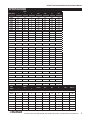
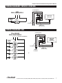
Delfield
™
®
E-Chef™ Series
Installation and Operation Manual
Please read this manual completely before attempting to install or operate this equipment! Notify carrier of damage! Inspect all
components immediately. See page 2.
N
CAUTIO
TION
A
M
R
O
T INF
N
A
T
R
O
USE
IMP
E
R
O
F
E
ONS!
I
T
C
READ B
U
R
INST
E
S
E
H
T
AVE
S
E
S
A
E
PL
Effective December 2007
E-Chef™ Series Installation and Operation Manual
CONTENTS
SERIAL NUMBER LOCATION................................................2
RECEIVING & INSPECTING...................................................2
SPECIFICATIONS...................................................................3
INSTALLATION......................................................................4
OPERATION...........................................................................5
MAINTENANCE......................................................................6
WIRING DIAGRAMS..............................................................7
DELFIELD FOOD WARMER (DFW) ASSEMBLIES
with infinite control..........................................................8
REPLACEMENT PARTS LISTS..............................................9
STANDARD WARRANTY................................................10-12
SERIAL NUMBER LOCATION
The serial number on all E-Chef™ Series models is printed
on the tag located on the plate shelf.
Always have the serial number of your unit available when
calling for parts or service. A complete list of authorized
Delfield parts depots is shown on the back cover of this
manual.
©2007 The Delfield Company. All rights reserved. Reproduction without
written permission is prohibited. “Delfield” is a registered trademark of The
Delfield Company.
Receiving and Inspecting the Equipment
Even though most equipment is shipped crated, care should
be taken during unloading so the equipment is not damaged
while being moved into the building.
1. Visually inspect the exterior of the package and skid or
container. Any damage should be noted and reported
to the delivering carrier immediately.
2. If damaged, open and inspect the contents with the
carrier.
3. In the event that the exterior is not damaged, yet upon
opening, there is concealed damage to the equipment
notify the carrier. Notification should be made verbally
as well as in written form.
4. Request an inspection by the shipping company of the
damaged equipment. This should be done within 10
days from receipt of the equipment.
5. Check the lower portion of the unit to be sure legs or
casters are not bent.
6. Also open the compressor compartment housing and
visually inspect the refrigeration package. Be sure lines
are secure and base is still intact.
7. Freight carriers can supply the necessary damage forms
upon request.
8. Retain all crating material until an inspection has been
made or waived.
Uncrating the Equipment
First cut and remove the banding from around the crate.
Remove the front of the crate material, use of some tools will
be required. If the unit is on legs remove the top of the crate
and lift the unit off the skid. If the unit is on casters it can be
"rolled" off the skid.
Delfield
™
2
For customer service, call (800) 733-8829, (800) 733-8821, (989) 773-7981, Fax (989) 773-3210, www.delfield.com
®
E-Chef™ Series Installation and Operation Manual
SPECIFICATIONS
MODEL NUMBER
OVERALL
VOLTS
AMPS
HZ
PHASE
36”
N/A
N/A
N/A
N/A
36”
N/A
N/A
N/A
N/A
31.5”
36”
N/A
N/A
N/A
N/A
24”
20”
34”
N/A
N/A
N/A
N/A
27”
20”
34”
N/A
N/A
N/A
N/A
ESOS32
32”
20”
34”
N/A
N/A
N/A
N/A
ESOS36
36”
20”
34”
N/A
N/A
N/A
N/A
ESOS48
48”
20”
34”
N/A
N/A
N/A
N/A
ESOS60
60”
20”
34”
N/A
N/A
N/A
N/A
ESOS64
64”
20”
34”
N/A
N/A
N/A
N/A
ESOS72
72”
20”
34”
N/A
N/A
N/A
N/A
ESOS74
74”
20”
34”
N/A
N/A
N/A
N/A
24”
31.5”
36”
N/A
N/A
N/A
N/A
L
D
H
ECOS24
24”
31.5”
ECOS36
36”
31.5”
ECOS48
48”
ESOS24
ESOS27
Openshelf modules
SINK MODULE
ECSR24
DOUBLE-TIER CANTILEVERED OVERSHELF ON OPENSHELF MODULE
EODC24
24”
28”
70”
N/A
N/A
N/A
N/A
EODC27
27”
28”
70”
N/A
N/A
N/A
N/A
EODC32
32”
28”
70”
N/A
N/A
N/A
N/A
EODC36
36”
28”
70”
N/A
N/A
N/A
N/A
EODC48
48”
28”
70”
N/A
N/A
N/A
N/A
EODC60
60”
28”
70”
N/A
N/A
N/A
N/A
EODC64
64”
28”
70”
N/A
N/A
N/A
N/A
EODC72
72”
28”
70”
N/A
N/A
N/A
N/A
EODC74
74”
28”
70”
N/A
N/A
N/A
N/A
36”
20”
34”
120
8.3
60
1
SOUPWELL MODULE
ESSW36
DOUBLE-TIER CANTILEVERED OVERSHELF ON SOUPWELL MODULE
EODC36S
36”
28”
70”
120
8.3
60
1
36”
20”
34”
N/A
N/A
N/A
N/A
ICE PAN MODULE
ESIC36
DOUBLE-TIER CANTILEVERED OVERSHELF ON ICE PAN MODULE
EODC36I
36”
28”
70”
N/A
N/A
N/A
N/A
24”
24”
20”
N/A
N/A
N/A
N/A
# OF WELLS
VOLTS
AMPS
HZ
MICROWAVE OVERSHELF
EOSM24
MODEL
NUMBER
OVERALL
L
D
H
PHASE
NEMA PLUG
HOT FOOD TABLES
EHEI36L
36”
31.5”
36”
2
120
17.0
60
1
5-30P
EHEI48L
48”
31.5”
36”
3
208/230
15.0/16.0
60
1
6-20P
EHEI60L
60”
31.5”
36”
4
208/230
20.0/22.0
60
1
6-30P
EHEI74L
74”
31.5”
36”
5
208/230
24.0/27.0
60
1
6-50P
EHEI36C
36”
31.5”
36”
2
120
17.0
60
1
5-30P
EHEI48C
48”
31.5”
36”
3
208/230
15.0/16.0
60
1
6-20P
EHEI60C
60”
31.5”
36”
4
208/230
20.0/22.0
60
1
6-30P
EHEI74C
74”
31.5”
36”
5
208/230
24.0/27.0
60
1
6-50P
Delfield
™
®
For customer service, call (800) 733-8829, (800) 773-8821, (989) 773-7981, Fax (989) 773-3210, www.delfield.com
3
E-Chef™ Series Installation and Operation Manual
Installation
Maximum weight for openshelves and
over shelves is 250 pounds. Overloading
shelves can damage equipment or cause
bodily injury.
Installation: essw36 & eodc36s Series (electric)
Installation should only be done by personnel
certified and licensed to install and maintain
electrical appliances.
Location
Intended for indoor use only. Do not install the hot food table near
any combustible objects or surfaces affected by heat or moisture.
Plumbing
A waste connection is provided 26.5” (67.3cm) above the floor,
1/2” from the gate valve. You must supply the required 1/2”
connection at gate valve.
Electrical connection
Connections must be made in accordance with all
applicable local codes and/or the National Electrical
Code. Refer to the wiring diagrams on page 10.
Flanged feet must be fastened to the floor.
Leveling
This unit must be level, both front and back and left to right, in
order to maintain an equal water depth throughout the wells.
Installation: ESIC36 & EODC36I Series
Plumbing
The unit’s drain must have an outlet to an appropriate drainage
area or container. The 1” IPC piece drain is shipped loose and
must be connected during installation.
Installation: EHEI Series (electric)
Installation should only be done by personnel
certified and licensed to install and maintain
electrical appliances.
Location
Intended for indoor use only. Do not install the hot food table near
any combustible objects or surfaces affected by heat or moisture.
Leveling
Plumbing
A waste connection is provided 26.5” (67.3cm) above the floor,
5.25” (13.3cm) from the right end. You must supply the required
1/2” connection at gate valve.
Electrical connection
Connections must be made in accordance with all
applicable local codes and/or the National Electrical
Code. Refer to the wiring diagrams on page 10.
This unit must be level, both front and back and left to right, in
order to maintain an equal water depth throughout the wells.
Delfield
™
4
For customer service, call (800) 733-8829, (800) 733-8821, (989) 773-7981, Fax (989) 773-3210, www.delfield.com
®
E-Chef™ Series Installation and Operation Manual
Operation: ESSW36, EODC36S & EHEI Series (electric)
Before the unit is used the first time for serving, turn the
temperature knob to HIGH and heat the well for 30 minutes. Any
residue or dust that adhered to the heater element(s) will burn off
during this initial preheat period.
When using thick sauces always operate the hot food well filled
with water. This will provide a more uniform temperature for the
sauce.
Steam can cause serious burns. Always wear some
type of protective covering on your hands and arms
when removing lids or pans from the unit. Lift the lid
or pan in a way that will direct escaping steam away
from your face and body.
Never place food directly into the well. Always use
pans.
Although these models may be operated either with or without
water in the wells, wet operation is recommended.
Always place covers on pans when not serving to prevent food
from drying out and to reduce your operating cost.
Wet operation
1) Fill food well with two inches of water. For quicker
pre-heating, use hot water to fill the well.
2) Turn the control to “HIGH” and pre-heat the warmer
for 30 minutes.
3) After pre-heating, set the control to your desired
serving temperature.
Dry operation
1) Pre-heat the well on “HIGH” for approximately 15
minutes.
2) After pre-heating, set the control to your desired
serving temperature.
Only 6” (15.2cm) deep insets should be used with a dry food well.
When operated dry, the bottom of the food well will discolor. A
mild abrasive cleaner is recommended to clean this discoloration.
Temperature
Water in wells . . . . . . . . . . . . . . . . . . . . . . . . . . . . . 160°F to 180°F
Product in pans . . . . . . . . . . . . . . . . . . . . . . . . . . . . 140°F to 160°F
For most efficient operation when empty, keep covered insets in
each well during preheating and when the well is not in use.
Do not put food down drain.
Delfield
™
®
For customer service, call (800) 733-8829, (800) 773-8821, (989) 773-7981, Fax (989) 773-3210, www.delfield.com
5
E-Chef™ Series Installation and Operation Manual
MAINTENANCE
The exterior can be cleaned using mild soap and warm water. If
this is not sufficient try ammonia and water or a non-abrasive
liquid cleaner. When cleaning the exterior, always rub with the
grain of the stainless steel to avoid marring the finish. Do not use
an abrasive cleaner because it will scratch the stainless steel. A
stainless steel cleaner or polish may be used to eliminate water
spotting and fingerprints and bring out the finish of the exterior.
The interior of the food wells should be cleaned daily with a
non-abrasive cleaner and non-abrasive pad. If necessary, a mild
abrasive may be used on the interior of the pans only. Hard water
stains and lime scaling may require a special cleaning product.
Never use steel wool.
stainless steel breakdown can consist of small pits and cracks. If
this has begun, clean thoroughly and start to apply stainless steel
cleaners in attempt to restore the passivity of the steel.
Do not use a hose or pressure washer on these
units. The water will damage the electrical
components.
Cleaning solutions need to be alkaline based or non-chloride
cleaners. Any cleaner containing chlorides will damage the
protective film of the stainless steel. Chlorides are also commonly
found in hard water, salts, and household and industrial cleaners. If
cleaners containing chlorides are used be sure to rinse repeatedly
and dry thoroughly upon completion. Routine cleaning of stainless
steel can be done with soap and water. Extreme stains or grease
should be cleaned with a non-abrasive cleaner and plastic scrub
pad. It is always good to rub with the grain of the steel. There
are also stainless steel cleaners available which can restore and
preserve the finish of the steels protective layer. Early signs of
Delfield
™
6
For customer service, call (800) 733-8829, (800) 733-8821, (989) 773-7981, Fax (989) 773-3210, www.delfield.com
®
(
76
HEATINGELEMENT
0
,
,
E-Chef™ Series (
Installation and Operation Manual
Wiring Diagrams: ESSW36 & EODC36S
LINEWIRES
INFINITECONTROL
WITHh/&&vPOSITION
.
,
PILOTLIGHTFURNISHED
6
3).',%0(!3%-/$%,3
,
'
.
(
pilot light (furnished)
).&).)4%
#/.42/,
(
(%!4%2
1000 w - 120V
H1
60(!3%-/$%,3
or 1000/1222 w P
0),/4,)'(4
LINEWIRES
.
6
3).',%0(!3%-/$%,3
0),/4,)'(4
Wiring Diagrams:
EHEI
,
' (%!4%2
.
0),/4,)'(4
(%!4%2
0),/4,)'(4
(%!4%2
60(!3%-/$%,3
(%!4%2
0),/4,)'(4
0),/4,)'(4
HEATER 1
).&).)4%
#/.42/,
PILOT LIgHT
0),/4,)'(4
HEATER 2
H1
'
, P ,
L1
L2
H2
).&).)4%
#/.42/,
L1 g
L2 L3
line wires
(%!4%2
PILOT LIgHT
0),/4,)'(4
(%!4%2
HEATER 3
0),/4,)'(4
120 or 208-240V
SINGLE
PHASE MODELS
HEATER 4
"INFINITE"
CONTROL
0),/4,)'(4
0),/4,)'(4
HEATER 5
L2
(NEUTRAL ON 120V MODELS)
to additional
(%!4%2
HEATER
1
food warmers
1000 W - 120V
or 1000/1222 W 208/240 V
heating element
,
208-240V 3 PHASE MODELS
(%!4%2
0),/4,)'(4
PILOT LIgHT
(%!4%2
(%!4%2
0),/4,)'(4
(NEUTRAL ON 120V MODELS)
0),/4,)'(4
"INFINITE"
CONTROL
).&).)4%
#/.42/,
(%!4%2
infinite control
(%!4%2
with “OFF” position
0),/4,)'(4
to additionalpilot
light (furnished)
food warmers
(%!4%2
0),/4,)'(4
L1
G
PILOT LIgHT
(%!4%2
208/230 V
heating element
0),/4,)'(4
120 or 208-240V
(%!4%2
).&).)4%
SINgLE
PHASE MODELS
#/.42/,
"INFINITE"
CONTROL
,
, ,
L1 '
L2
INFINITECONTROL
H2
WITHh/&&vPOSITION
,
).&).)4%
#/.42/,
line wires
0),/4,)'(4
(%!4%2
L1
g
L2
76
HEATINGELEMENT
0
,
,
infinite control
with “OFF” position
"INFINITE"
CONTROL
(%!4%2
0),/4,)'(4
(%!4%2
0),/4,)'(4
HEATER 3
0),/4,)'(4
PILOT LIgHT
PILOT LIgHT
HEATER 4
(%!4%2
HEATER 6
PILOT LIgHT
0),/4,)'(4
PILOT LIgHT
HEATER 2
PILOT LIgHT
PILOT LIgHT
HEATER 1
HEATER 6
PILOT LIGHT
PILOT LIgHT
HEATER 5
208-240V 3 PHASE MODELS
PILOT LIgHT
L1
HEATER 2
G
L2
L3
PILOT LIGHT
HEATER 3
PILOT LIGHT
HEATER 4
PILOT LIGHT
HEATER 5
PILOT LIGHT
Delfield
™
®
HEATER 6
PILOT LIGHT
"INFINITE"
CONTROL
HEATER 1
"INFINITE"
CONTROL
HEATER 3
PILOT LIGHT
PILOT LIGHT
HEATER 4
HEATER 6
PILOT LIGHT
PILOT LIGHT
HEATER 2
PILOT LIGHT
HEATER 5
PILOT LIGHT
For customer service, call (800) 733-8829, (800) 773-8821, (989) 773-7981, Fax (989) 773-3210, www.delfield.com
7
E-Chef™ Series Installation and Operation Manual
Delfield Food Well (DFW) Assembly: with infinite control
10
2
4
INFINITE
CONTROL
7
KEY
1
9
8
6
5
11
8.50
2.31
CLE
AR
DRAIN
OPTIONAL
3
PART NAME
DELFIELD PART #
Complete assembly, 120V, infinite w/drain
Complete assembly, 120V, infinite w/o drain
Complete assembly, 208V, infinite w/drain
Complete assembly, 208V, infinite w/o drain
1
Deflector plate
2
Bottom cover
3
Food well, with drain
Food well, without drain
4
Screw
5
Element, 120V
Element, 208V
6
Screws (2)
7
Insulation
8
Thermostat non-adjustable
9
Screw
10
Drain cover
11
Screws (2)
12
Infinite control, 120V
Infinite control, 240V
13
Infinite control knob
14
Pilot light, red, 120V
Pilot light, amber, 240V
000-516-0000
000-517-0000
000-518-0000
000-519-0000
026-061-0001
026-103-0001
323-4361
323-4362
932-1353
219-4006
219-4007
932-1379
343-4663
219-4335
932-1007
027-210-0001
932-1007
219-4107
219-4110
323-4557
219-4190
219-4095
14
12
13
Delfield
™
8
For customer service, call (800) 733-8829, (800) 733-8821, (989) 773-7981, Fax (989) 773-3210, www.delfield.com
®
Miscellaneous Parts Lists
E-Chef™ Series Installation and Operation Manual
ESSW36 & EODC36S Series (electric)
ACCESSORY MODELS
PART NAME
MODEL #
NAME
EORW14
Top shelf vertical raceway, 14”
EORW18
Bottom shelf vertical raceway, 18”
EORW24
Top shelf to ceiling vertical raceway, 24”
EORW36
Top shelf to ceiling vertical raceway, 36”
EORW48
Top shelf to ceiling vertical raceway, 48”
ESRW24
Server side horizontal raceway, 24”
ESRW27
Server side horizontal raceway, 27”
ESRW32
Server side horizontal raceway, 32”
ESRW36
Server side horizontal raceway, 36”
ESRW48
Server side horizontal raceway, 48”
ESRW60
Server side horizontal raceway, 60”
ESRW64
Server side horizontal raceway, 64”
ESRW72
Server side horizontal raceway, 72”
ESRW74
Server side horizontal raceway, 74”
DELFIELD PART #
Bullet feet (4) . . . . . . . . . . . . . . . . . . . . . . . . . . . . . . . . 3234224
Casters . . . . . . . . . . . . . . . . . . . . . . . . . . 3234160 & 3234161
Leg . . . . . . . . . . . . . . . . . . . . . . . . . . . . . . . . . . . . . . . . 3234645
Gate valve, 1/2” . . . . . . . . . . . . . . . . . . . . . . . . . . . . . . 3547486
Flanged feet . . . . . . . . . . . . . . . . . . . . . . . . . . . . . . . . . 3234339
1” plastic drain . . . . . . . . . . . . . . . . . . . . . . . . . . . . . . 3234242
EHEI Series (electric)
PART NAME
DELFIELD PART #
Cutting board pin cap . . . . . . . . . . . . . . . . . . . . . . . . . 1701000
Cutting board pin screw . . . . . . . . . . . . . . . . . . . . . . . 9321076
Brass cutting board hinge pin . . . . . . . . . . . . . . . . . . . 3234360
Polyethlene board, model EHEI36 . . . . . . . . . . . 096-004-0031
Polyethlene board, model EHEI48 . . . . . . . . . . . 096-004-0032
Polyethlene board, model EHEI60 . . . . . . . . . . . 096-004-0033
Polyethlene board, model EHEI74 . . . . . . . . . . . 096-004-0034
ECFP
Delfield
™
Stainless steel end filler panel
ECPB114
Stainless steel flashing, PTB, rail
ECPB99
Stainless steel flashing, PTB, rail
ECPB91
Stainless steel flashing, PTB, rail
ECPB72
Stainless steel flashing, PTB, rail
ECPB60
Stainless steel flashing, PTB, rail
ECPB48
Stainless steel flashing, PTB, rail
®
For customer service, call (800) 733-8829, (800) 773-8821, (989) 773-7981, Fax (989) 773-3210, www.delfield.com
9
E-Chef™ Series Installation and Operation Manual
Standard Labor Guidelines To Repair or Replace Parts on Delfield Equipment
Advice and recommendations given by Delfield Service Technicians do not constitute or guarantee any special coverage.
•A maximum of 1-hour is allowed to diagnose a defective component.
•A maximum of 1-hour is allowed for retrieval of parts not in stock.
•A maximum travel distance of 100 miles round trip and 2-hours will be reimbursed.
•Overtime, installation/start-up, normal control adjustments, general maintenance, glass breakage, freight damage, and/or
correcting and end-user installation error will not be reimbursed under warranty unless pre-approved with a Service Work
Authorization from Delfield. You must submit the number with the service claim.
LABOR OF 1-HOUR IS ALLOWED TO REPLACE:
•Contactor/Relay
•Infinite Switch
•Hi-limit/Thermal Protector Switch
•Water Level Sensor/Probe
LABOR OF 2 HOURS TO REPLACE:
•Heating Element
•Solenoid Valve
Delfield
™
10
For customer service, call (800) 733-8829, (800) 733-8821, (989) 773-7981, Fax (989) 773-3210, www.delfield.com
®
E-Chef™ Series Installation
and Operation Manual
8,3ERIES3ERVICEAND)NSTALLATION-ANUA
34!.$!2$/.%9%!27!22!.49/.%9%!20!243!.$,!"/2
4HE$ELlELD#OMPANYh$ELlELDvWARRANTSTOTHE/RIGINAL0URCHASER
OFTHE$ELlELDPRODUCTHEREINCALLEDTHEh5NITvTHATSUCH5NITANDALL
PARTSTHEREOFWILLBEFREEFROMDEFECTSINMATERIALANDWORKMANSHIP
UNDERNORMALUSEANDSERVICEFORAPERIODOFONEYEARFROM
THEDATEOFSHIPMENTOFTHE5NITTOTHE/RIGINAL0URCHASERORIFTHE
/RIGINAL0URCHASERRETURNSTHEWARRANTYCARDCOMPLETELYlLLEDOUT
INCLUDINGTHEDATEOFINSTALLATIONWITHINTHIRTYDAYSOFRECEIPT
OFTHE5NITONEYEARFROMTHEDATEOFINSTALLATION$URINGTHIS
ONEYEARWARRANTYPERIOD$ELlELDWILLREPAIRORREPLACEANYDEFECTIVE
PARTORPORTIONTHEREOFRETURNEDTO$ELlELDBYTHE/RIGINAL0URCHASER
WHICH$ELlELDDETERMINESWASDEFECTIVEDUETOFAULTYMATERIALOR
WORKMANSHIP4HE/RIGINALPURCHASERWILLPAYALLLABORCRATINGFREIGHT
ANDRELATEDCOSTSINCURREDINTHEREMOVALOFTHE5NITOFDEFECTIVE
COMPONENTANDSHIPMENTTO$ELlELDEXCEPTTHATDURINGAPERIODOF
EITHERNINETYDAYSFROMTHEDATEOFSHIPMENTOFTHE5NITTOTHE
/RIGINAL0URCHASERORIFTHE/RIGINAL0URCHASERRETURNSTHEWARRANTY
CARDCOMPLETELYlLLEDOUTINCLUDINGTHEDATEOFINSTALLATIONWITHINTHIRTY
DAYSOFRECEIPTOFTHE5NITNINETYDAYSFROMTHEDATEOF
INSTALLATION$ELlELDWILLPAYALLRELATEDLABORCOSTS$ELlELDWILLPAYTHE
RETURNCOSTSIFTHE5NITORPARTTHEREOFWASDEFECTIVE
4HETERMh/RIGINAL0URCHASERvASUSEDHEREINMEANSTHATPERSONlRM
ASSOCIATIONORCORPORATIONFORWHOMTHE5NITWASORIGINALLYINSTALLED
4HISWARRANTYDOESNOTAPPLYTOANY5NITORPARTTHEREOFTHATHAS
BEENSUBJECTEDTOMISUSENEGLECTALTERATIONORACCIDENTSUCHAS
ACCIDENTALDAMAGETOTHEEXTERIORlNISHOPERATEDCONTRARYTOTHE
RECOMMENDATIONSSPECIlEDBY$ELlELDORREPAIREDORALTEREDBYANYONE
OTHERTHAN$ELlELDINANYWAYSOASTOIN$ELlELDSSOLEJUDGEMENT
AFFECTITSQUALITYOREFlCIENCY4HISWARRANTYDOESNOTAPPLYTOANY5NIT
THATHASBEENMOVEDFROMTHELOCATIONWHEREITWASORIGINALLYINSTALLED
4HISWARRANTYALSODOESNOTCOVERTHEREFRIGERATORDRIERORTHELIGHT
BULBSUSEDINTHE5NIT4HEWARRANTYISSUBJECTTOTHEUSERSNORMAL
MAINTENANCEANDCARERESPONSIBILITYASSETFORTHINTHE3ERVICEAND
)NSTALLATION-ANUALSUCHASCLEANINGTHECONDENSERCOILANDISIN
LIEUOFALLOTHEROBLIGATIONSOF$ELlELD$ELlELDNEITHERASSUMESNOR
AUTHORIZESANYOTHERPERSONTOASSUMEFOR$ELlELDANYOTHERLIABILITY
INCONNECTIONWITH$ELlELDSPRODUCTS
2EMOVALORDEFACEMENTOFTHEORIGINAL3ERIAL.UMBEROR-ODEL.UMBER
FROMANY5NITSHALLBEDEEMEDTORELEASE$ELlELDFROMALLOBLIGATIONS
HEREUNDERORANYOTHEROBLIGATIONSEXPRESSORIMPLIED
0ARTSFURNISHEDBYSUPPLIERSTO$ELlELDAREGUARANTEEDBY$ELlELDONLY
TOTHEEXTENTOFTHEORIGINALMANUFACTURERSEXPRESSWARRANTYTO$ELlELD
&AILUREOFTHE/RIGINAL0URCHASERTORECEIVESUCHMANUFACTURERSEXPRESS
WARRANTYTO$ELlELD&AILUREOFTHE/RIGINAL0URCHASERTORECEIVESUCH
MANUFACTURERSWARRANTYSHALLINNOWAYCREATEANYWARRANTYEXPRESSED
ORIMPLIEDORANYOTHEROBLIGATIONORLIABILITYON$ELlELDSPARTINRESPECT
THEREOF
)&4(%#534/-%2)353).'!0!244(!42%35,43).!6/)$%$
7!22!.49!.$!$%,&)%,$!54(/2):%$2%02%3%.4!4)6%
42!6%,34/4(%).34!,,!4)/.!$$2%334/0%2&/2-7!22!.49
3%26)#%4(%3%26)#%2%02%3%.4!4)6%7),,!$6)3%#534/-%2
4(%7!22!.49)36/)$35#(3%26)#%#!,,37),,"%"),,%$
4/#534/-%2!44(%!54(/2):%$3%26)#%#%.4%234(%.
!00,)#!",%4)-%!.$-!4%2)!,32!4%3#/.3)$%2#534/-%2
-!9).)4)!4%!3%26)#%!'2%%-%.47)4(/540!243#/6%2!'%
)FSHIPMENTOFAREPLACEMENTPARTISREQUESTEDPRIORTOTHEARRIVALIN
THE$ELlELDFACTORYOFTHEPARTCLAIMEDTOBEDEFECTIVETHE/RIGINAL
0URCHASERMUSTACCEPTDELIVERYOFTHEREPLACEMENTPARTOFA#/$
Delfield
™
BASISWITHCREDITBEINGISSUEDAFTERTHEPARTHASBEENRECEIVEDAND
INSPECTEDAT$ELlELDSPLANTANDDETERMINEDBY$ELlELDTOBEWITHINTHIS
WARRANTY
5NDERNOCONDITIONDOESTHISWARRANTYGIVETHE/RIGINAL0URCHASERTHE
RIGHTTOREPLACETHEDEFECTIVE5NITWITHACOMPLETE5NITOFTHESAME
MANUFACTUREROROFANOTHERMAKE5NLESSAUTHORIZEDBY$ELlELDIN
WRITINGTHISWARRANTYDOESNOTPERMITTHEREPLACEMENTOFANYPART
INCLUDINGTHEMOTORCOMPRESSORTOBEMADEWITHTHEPARTOFANOTHER
MAKEORMANUFACTURER
.OCLAIMSCANBEMADEUNDERTHISWARRANTYFORSPOILAGEOFANYPRODUCTS
FORANYREASONINCLUDINGSYSTEMFAILURE
4HEINSTALLATIONCONTRACTORSHALLBERESPONSIBLEFORBUILDINGACCESS
ENTRANCEANDlELDCONDITIONSTOINSURESUFlCIENTCLEARANCETOALLOWANY
HOODSVENTSOR5NITSIFNECESSARYTOBEBROUGHTINTOTHEBUILDING
$ELlELDWILLNOTBERESPONSIBLEFORSTRUCTURALCHANGESORDAMAGES
INCURREDDURINGINSTALLATIONOFTHE5NITORANYEXHAUSTSYSTEM
$ELlELDSHALLNOTBELIABLEINANYMANNERFORANYDEFAULTORDELAYIN
PERFORMANCEHEREUNDERCAUSEDBYORRESULTINGFROMANYCONTINGENCY
BEYOND$ELlELDSCONTROLINCLUDINGBUTNOTLIMITEDTOWAR
GOVERNMENTALRESTRICTIONSORRESTRAINTSSTRIKELOCKOUTSINJUNCTIONS
lREmOODACTSOFNATURESHORTORREDUCEDSUPPLYOFRAWMATERIALSOR
DISCONTINUANCEOFTHEPARTSBYTHEORIGINALPARTMANUFACTURER
%XCEPTASPROVIDEDINANY!DDITIONAL&OUR9EAR0ROTECTION0LAN
IFAPPLICABLEANDTHE3ERVICE,ABOR#ONTRACTIFAPPLICABLETHE
FOREGOINGISEXCLUSIVEANDINLIEUOFALLOTHERWARRANTIESWHETHER
WRITTENORORALEXPRESSORIMPLIED4HISWARRANTYSUPERSEDES
ANDEXCLUDESANYPRIORORALORWRITTENREPRESENTATIONSOR
WARRANTIES$ELlELDEXPRESSLYDISCLAIMSANYIMPLIEDWARRANTIES
OFMERCHANTABILITYlTNESSFORAPARTICULARPURPOSEOFCOMPLIANCE
WITHANYLAWTREATYRULEORREGULATIONRELATINGTOTHEDISCHARGEOF
SUBSTANCESINTOTHEENVIRONMENT4HESOLEANDEXCLUSIVEREMEDIES
OFANYPERSONRELATINGTOTHE5NITANDTHEFULLLIABILITYOF$ELlELDFOR
ANYBREACHOFTHISWARRANTYWILLBEASPROVIDEDINTHISWARRANTY
/THERTHANTHIS$ELlELD3TANDARD/NE9EAR,IMITED7ARRANTYANY
APPLICABLE$ELlELD!DDITIONAL&OUR9EAR0ROTECTION0LANORAPPLICABLE
$ELlELD3ERVICE,ABOR#ONTRACTTHE/RIGINAL0URCHASERAGREESAND
ACKNOWLEDGESTHATNOOTHERWARRANTIESAREOFFEREDORPROVIDEDIN
CONNECTIONWITHORFORTHEUNITORANYOTHERPARTTHEREOF
)NNOEVENTWILL$ELlELDBELIABLEFORSPECIALINCIDENTALORCONSEQUENTIAL
DAMAGESORFORDAMAGESINTHENATUREOFPENALTIES
)&$52).'4(%7!22!.490%2)/$#534/-%253%3!0!24&/2
4()3$%,&)%,$%15)0-%.4/4(%24(!.!.5.-/$)&)%$.%7
/22%#9#,%$0!24052#(!3%$$)2%#4,9&2/-$%,&)%,$/2
!.9/&)43!54(/2):%$3%26)#%#%.4%23!.$/24(%0!24
"%).'53%$)3-/$)&)%$&2/-)43/2)').!,#/.&)'52!4)/.
4()37!22!.497),,"%6/)$&524(%2$%,&)%,$!.$)43
!&&),)!4%37),,./4"%,)!",%&/2!.9#,!)-3$!-!'%3/2
%80%.3%3).#522%$"94(%#534/-%27()#(!2)3%$)2%#4,9
/2).$)2%#4,9).7(/,%/2).0!24$5%4/4(%).34!,,!4)/.
/&!.9-/$)&)%$0!24!.$/20!242%#%)6%$&2/-!.
5.!54(/2):%$3%26)#%#%.4%2)FTHEWARRANTYBECOMESVOID
#USTOMERMAYPURCHASEFROM$ELlELDIFAVAILABLEA3ERVICE
!GREEMENTORSERVICEATTHETHENCURRENTTIMEANDMATERIALSRATE
&ORMOREINFORMATIONON$ELlELDWARRANTYSLOGONANDCHECKOUTTHE
SERVICESECTIONOFOURWEBSITEATWWWDELlELDCOM
®
11
For customer service, call (800) 733-8829, (800) 773-8821, (989) 773-7981, Fax (989) 773-3210, www.delfield.com
&ORCUSTOMERSERVICECALL&AXWWWDELlELDCOM
E-Chef™ Series Installation and Operation Manual
Additional Four Year Protection Plan
Delfield Model#
Serial #
Installation
Date
In addition to the Standard One Year Warranty on the MotorCompressor contained in the above listed Delfield product (the
“Unit”), The Delfield Company (“Delfield”) also agrees to repair, or
exchange with similar or interchangeable parts in design and capacity
at Delfield’s option, the defective Motor-Compressor contained in the
Unit (the “Motor-Compressor), or any part thereof, for the Original
Purchaser only, at any time during the four (4) years following the
initial one (1) year period commencing on the date of installation for
the Original Purchaser. Failure of the Original Purchaser to register
the registration card containing the Original Purchasers name,
address, date of installation, model number and serial number of
the Unit containing the Motor-Compressor within 30 days from the
date of installation shall void this warranty. This additional warranty
is only available if the Motor-Compressor is inoperative due to defects
in material or factory workmanship, as determined by Delfield in
its sole judgement and discretion. The Original Purchaser shall be
responsible for returning the defective Motor-Compressor to Delfield
prepaid, F.O.B. at the address shown on the back cover of this manual.
The term “Original Purchaser” as used herein means that person, firm,
association, or corporation for whom the Unit was originally installed.
The term “Motor-Compressor” as used herein does not include unit
base, air or water cooled condenser, receiver, electrical accessories
such as relay, capacitors, refrigerant controls, or condenser fan/motor
assembly. This warranty does not cover labor charges incidental to
the replacement of parts. This warranty further does not include
any equipment to which said condensing unit is connected, such as
cooling coils, temperature controls or refrigerant metering devices.
This warranty shall be void if the Motor-Compressor, in Delfield’s
sole judgement, has been subjected to misuse, neglect, alteration
or accident, operated contrary to the recommendations specified
by the Unit manufacturer, repaired or altered by anyone other than
Delfield in any way so as, in Delfield’s sole judgment, to affect its
quality or efficiency or if the serial number has been altered, defaced
or removed. This Warranty does not apply to a Motor-Compressor in
any Unit that has been moved from the location where it was originally
installed. The addition of methyl chloride to the condensing unit or
refrigeration system shall void this warranty.
(for Motor-Compressor only)
General Conditions
Delfield shall not be liable in any manner for any default or delay
in performance hereunder caused by or resulting from any
contingency beyond Delfield’s control, including, but not limited
to, war, governmental restrictions or restraints, strike, lockouts,
injunctions, fire, flood, acts of nature, short or reduced supply
of raw materials, or discontinuance of any part or the MotorCompressor by the unit manufacturer.
Replacement of a defective Motor-Compressor is limited to one (1)
Motor-Compressor by us during the four (4) year period. Delfield
shall replace the Motor-Compressor at no charge.
This warranty does not give the Original Purchaser of the MotorCompressor the right to purchase a complete replacement MotorCompressor of the same make or of another make. It further does
not permit the replacement to be made with a Motor-Compressor
of another kind unless authorized by Delfield. In the event Delfield
authorizes the Original Purchaser to purchase a replacement
Motor-Compressor locally, only the wholesale cost of the MotorCompressor is refundable.
Expressly excluded from this warranty are damages resulting from
spoilage of goods.
Except as provided in any applicable Standard One Year Limited
Warranty or applicable Service Labor Contract, the foregoing
is exclusive and in lieu of all other warranties, whether written
or oral, express or implied. This Warranty supersedes and
excludes any prior oral or written representations or warranties.
Delfield expressly disclaims any implied warranties of
merchantability, fitness for a particular purpose or compliance
with any law, treaty, rule or regulation relating to the MotorCompressor, and the full liability of Delfield for any breach of this
warranty, will be as provided in this warranty.
Other than any applicable Delfield Standard One year Limited
Warranty, this Delfield Additional Four Year Protection Plan and any
applicable Delfield Service Labor Contract, the Original Purchaser
agrees and acknowledges that no other warranties are offered or
provided in connection with or for the Motor-Compressor or any
part thereof.
In no event will Delfield be liable for special, incidental or
consequential damages, or for damages in the nature of penalties.
Delfield
™
12
For customer service, call (800) 733-8829, (800) 733-8821, (989) 773-7981, Fax (989) 773-3210, www.delfield.com
®
E-Chef™ Series Installation and Operation Manual
NOTES:
Delfield
™
®
For customer service, call (800) 733-8829, (800) 773-8821, (989) 773-7981, Fax (989) 773-3210, www.delfield.com
13
E-Chef™ Series Installation and Operation Manual
NOTES:
Delfield
™
14
For customer service, call (800) 733-8829, (800) 733-8821, (989) 773-7981, Fax (989) 773-3210, www.delfield.com
®
E-Chef™ Series Installation and Operation Manual
NOTES:
Delfield
™
®
For customer service, call (800) 733-8829, (800) 773-8821, (989) 773-7981, Fax (989) 773-3210, www.delfield.com
15
Delfield
™
Mt. Pleasant, MI
®
Covington, TN
Thank you for choosing Delfield!
Help is a phone call away. Help our team of professional, courteous
customer service reps by having your model number and serial number
available at the time of your call (800) 733-8829.
Model:_____________________ S/N: ____________________
Installation Date:_____________
For a list of Delfield’s authorized parts depots,
visit our website at www.delfield.com.
980 S. Isabella Rd., Mt. Pleasant, MI 48858, U.S.A. • +1(989) 773-7981 or (800) 733-8829 • Fax (866) 779-2040 • www.delfield.com
Delfield reserves the right to make changes in design or specifications without prior notice. ©2007 The Delfield Company. All rights reserved. Printed in the U.S.A.
DMECHEF 12/07