Download Agilent Technologies 34134A User`s guide
Transcript
34134A.book Page 1 Wednesday, March 25, 2009 4:09 PM
User’s Guide
Publication number 34134-90001
April 2009
For Safety information, Warranties, Regulatory information, and publishing information, see the
pages at the back of this book.
© Copyright Agilent Technologies 1999, 2009
All Rights Reserved.
34134A AC/DC DMM Current Probe
34134A.book Page 2 Wednesday, March 25, 2009 4:09 PM
Contents
Inspect the probe . . . . . . . . . . . . . . . . . . . . . . . . . . . . . . . . . .
Description . . . . . . . . . . . . . . . . . . . . . . . . . . . . . . . . . . . . . .
Compatibility . . . . . . . . . . . . . . . . . . . . . . . . . . . . . . . . . .
Control and Connector Identification Information . . . . .
Specifications and characteristics . . . . . . . . . . . . . . . . . . . . .
Electrical Specifications . . . . . . . . . . . . . . . . . . . . . . . . .
Environmental Characteristics. . . . . . . . . . . . . . . . . . . . .
Mechanical Characteristics . . . . . . . . . . . . . . . . . . . . . . .
Safety Specifications . . . . . . . . . . . . . . . . . . . . . . . . . . . .
Operation . . . . . . . . . . . . . . . . . . . . . . . . . . . . . . . . . . . . . . .
Calibration . . . . . . . . . . . . . . . . . . . . . . . . . . . . . . . . . . . . . .
Repair . . . . . . . . . . . . . . . . . . . . . . . . . . . . . . . . . . . . . . . . . .
To check/replace the battery . . . . . . . . . . . . . . . . . . . . . .
Cleaning the probe. . . . . . . . . . . . . . . . . . . . . . . . . . . . . .
Declaration of Conformity . . . . . . . . . . . . . . . . . . . . . . . . . .
2
3
3
3
4
4
5
5
6
7
8
8
8
8
13
Inspect the probe
❏ Inspect the shipping container for damage.
Keep a damaged shipping container or cushioning material until the contents of the
shipment have been checked for completeness and the probe has been checked
mechanically and electrically.
❏ Inspect the instrument.
•
•
2
If there is mechanical damage or defect, or if the probe does not operate properly
or pass performance tests, notify your Agilent Sales Office.
If the shipping container is damaged, or the cushioning materials show signs of
stress, notify the carrier as well as your Agilent Sales Office. Keep the shipping
materials for the carrier’s inspection. The Agilent office will arrange for repair or
replacement at Agilent’s option without waiting for claim settlement.
34134A.book Page 3 Wednesday, March 25, 2009 4:09 PM
34134A AC/DC DMM Current Probe
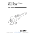
The 34134A Current Probe measures low DC or AC from 10 mA to 50 A DC,
40 A AC. This battery-powered clamp-on probe may be used with digital multimeters,
voltmeters, or other voltage-measuring instruments. The probe jaws clamp around the
conductor under test, allowing current measurements without breaking the circuit.
Hall sensor technology senses the magnetic field produced by the current measured,
and generates a millivolt DC or AC output signal. The narrow jaw is designed for
optimum use in crowded wiring in industrial and automotive environments.
Compatibility
The 34134A Current Probe is compatible with any DMM, or other voltage measuring
instrument which has the following features:
• Range and resolution capable of displaying 1 mV of input.
• Voltmeter accuracy (uncertainty) of 0.75% or better to take full advantage of the
accuracy of the probe.
• Minimum input impedance of 100 k Ω (1 V/A range) or 10 k Ω (10 mV/A range).
• Input jacks that accept 4mm shrouded banana plugs.
Zero Adjust Knob
Range Selection Switch
Power Indication LED
∅ = 11.8mm
Battery Compartment Cover
Control and Connector Identification
3
34134A.book Page 4 Wednesday, March 25, 2009 4:09 PM
34134A AC/DC DMM Current Probe
Specifications and characteristics
Specifications and characteristics
Operating and environmental characteristics of the 34134A Current Probes are
shown below.
Electrical Specifications
Current Range
Output Signal (AC/DC)
Accuracy*
1 V/A Range (1 mV/mA)
DC: 10 mA to 2 A
AC: 10 mA to 1.5 A
1 mV/mA (2 V @ 2 A)
± 2% reading ± 5mA
Frequency Range
DC to 8 kHz @ -3 dB
Phase Shift
DC to 65 Hz: 1 °
Minimum Input Resistance 100 k Ω
of Instrument
Noise
DC to 1 Hz: 1.5 mV
1 Hz to 10 kHz: 14 mV
0 kHz to 100 kHz: 18 mV
Slew Rate @ 5 A
120 mV/ µ s
10 mV/A Range
DC: 100 mA to 80 A
AC: 100 mA to 60 A
10 mV/A
500 mA to 50 A DC/40 A
AC: ±4% reading ±220 mA
50 to 80A DC: ±12%
reading
0 to 60A AC: ±12% reading
DC to 8 kHz
DC to 65 Hz: 1 °
100 k Ω
DC to 1 Hz: 15 µ V
1 Hz to 10 kHz: 140 µ V
0 kHz to 100 kHz: 180 µ V
5.5 mV/ µ s
* Accuracies are given for an ambient temperature of 23 °C ±3 °C, relative humidity of 20 to 75%,
conductor centered in jaw window, probe zeroed, no hysteresis in DC, DC to 40 to 100Hz sine wave (1mV/
mA range) or DC and 40 to 1 kHz sine wave (10mV/A range), 1 minute warm-up, battery at 9V, appropriate
load impedance, magnetic field <40A/m and no common mode.
4
34134A.book Page 5 Wednesday, March 25, 2009 4:09 PM
34134A AC/DC DMM Current Probe
Specifications and characteristics
Typical Frequency Response Curve
Voltage vs Frequency Response Curve
Environmental Characteristics
Operating Temperature 0 to 50°C
Storage Temperature
-30 to 80°C
Operating relative
0 to 50 °C, 0 to 85% relative humidity
humidity
Temperature Coefficient 800 ppm per °C +10 mA/°C typical from -10 to 50°C
Altitude
Operating: 0 to 2000 m
Non-operating: 0 to 12,000 m
Mechanical Characteristics
Zero Adjustment
Maximum cable diameter
Dimensions
Weight
Color
Material
Output Cable
20 turn potentiometer
11.8 mm
67 x 231 x 36 mm
330g with battery
Grey
Fiberglass charged polycarbonate
1.5m double insulated lead with shielded banana plugs
5
34134A.book Page 6 Wednesday, March 25, 2009 4:09 PM
34134A AC/DC DMM Current Probe
Specifications and characteristics
Safety Specifications
Working voltage
Case protection
Drop test
Mechanical shock
Vibration
!
600 V CAT III
IP20 per IEC 529
1m according to IEC 68-2-32
100 G: test per IEC 68-2-27
Test per IEC 68-2-6 frequency range 10 Hz to 55 Hz,
amplitude: 0.15mm
This symbol signifies that the 34134A AC/DC DMM Current Probe is
protected by double or reinforced insulation. Only use specified replacement
parts when servicing the instrument.
This symbol signifies CAUTION! and requests that the user refer to the user
manual before using the instrument.
WARNING SHOCK HAZARD!
• Connect the probe to the DMM or voltage measuring instrument before clamping
!
the probe around a conductor.
• Never use the probe on circuits rated higher than 660 V.
• Never leave the probe clamped around a conductor while not connected to a voltage
measuring instrument or DMM.
• Carefully center the conductor inside the probe jaws and make sure that the probe
is perpendicular to the conductor before closing the jaws.
• Avoid, if possible, the proximity of other conductors which may create noise.
• Check the magnetic mating surfaces of the probe jaws; these should be free of dirt,
rust, or other foreign matter.
• Do not use a probe which is cracked, damaged or has defective leads.
6
34134A.book Page 7 Wednesday, March 25, 2009 4:09 PM
34134A AC/DC DMM Current Probe
Operation
Operation
1 Connect the probe to the multimeter or other instrument.
CAUTION
Be sure to observe the polarities: red = positive terminal, black = common terminal.
2 Select the multimeter range which best corresponds to the measured current.
For better reading stability, you may use the DMM 2 Volt range and let the probe “warm
up” for one minute before zeroing.
The Current Probe has a dual output, DC V output in DC and AC V output in AC.
• The “1 V/A” range has an output signal of 1 mV/mA AC/DC with an output of 2
volts representing 2 amps present in the conductor being measured.
• The “10 mV/A” range has an output signal of 10 mV/A AC/DC with an output of
500 millivolts representing 50 amps present in the conductor being measured.
3 Zero the probe in DC and in DC coupled AC measurements.
When the 34134A Current Probe has been used for a current measurement and then
removed from the conductor, a small amount of residual magnetism often remains in
the core. This residual magnetism will cause the voltmeter to show a small DC reading
even though there is no current passing through the jaws of the probe. The residual
magnetism should not cause a problem for AC current measurement because the AC
voltage function in most multimeters is AC coupled. DC offset caused by the residual
magnetism will contribute to reading errors, but can be minimized by using the zero
adjust knob to show a reading of 0 ± a few counts on the multimeter (probe not clamped
on a conductor).
There will always be some instability and noise generated by the Hall sensor, the earth
magnetic field and environmental noise. This is particularly noticeable on the most
sensitive range, 1 V/A (1 mV/mA), where you may have up to 5 mV of uncertainty,
which cannot be “zeroed out.” “Zero” the probe while it is connected to the DMM and
on the range to be used. Let the probe warm-up for one minute before zeroing. Turn
the zero adjustment knob until the probe is zeroed.
4 Observe the output polarities for DC measurement.
5 Clamp the probe on the conductor to be measured and read the current flowing
directly on your meter.
The output of the probe is 10 mV/A AC/DC or 1 mV/mA AC/DC. If your meter
indicates a negative reading during DC measurements, this simply means that the
current flow is in the opposite direction of the arrows marked “I” on the probe or that
the probe connections are reversed (polarity).
6 After measurement, turn the probe OFF.
7
34134A.book Page 8 Wednesday, March 25, 2009 4:09 PM
34134A AC/DC DMM Current Probe
Calibration
Calibration
To guarantee that your instrument complies with the factory specifications, we
recommend that the 34134A Current Probe be submitted to your local Agilent
Service Center at one year intervals for recalibration, or as required by other standards.
Repair
This probe contains no user serviceable parts. Please return to your local Agilent
Service Center for repair.
To check/replace the battery
When the probe is turned on, the green LED should light up. If not, replace the 9 V
battery.
1 Disconnect the probe from the circuit and the DMM.
2 Turn the probe “OFF.”
3 Unscrew the battery compartment screw and pull out the battery compartment
cover.
4 Replace the battery and put the cover back up.
CAUTION
Do not replace the battery while the probe is in use.
Cleaning the probe
Be sure that the mating surfaces of the jaw are free of dirt or foreign matter. If they are
rusted, gently clean with a soft, lightly oiled cloth.
8
34134A.book Page 0 Wednesday, March 25, 2009 4:09 PM
© Agilent Technologies
1999, 2009
All Rights Reserved.
Reproduction, adaptation, or
translation without prior
written permission is
prohibited, except as allowed
under the copyright laws.
Restricted Rights Legend.
Use, duplication or disclosure
by the U.S. Government is
subject to restrictions as set
forth in subparagraph (c) (1)
(ii) of the Rights in Technical
Data and Computer Software
clause at DFARS 252.2277013 for DOD agencies, and
subparagraphs (c) (1) and (c)
(2) of the Commercial
Computer Software Restricted
Rights clause at FAR 52.22719 for other agencies.
Document Warranty
The information contained in
this document is subject to
change without notice.
Agilent makes no warranty
of any kind with regard to
this material, including, but
not limited to, the implied
warranties of
merchantability or fitness
for a particular purpose.
Agilent shall not be liable for
errors contained herein or for
damages in connection with
the furnishing, performance,
or use of this material.
Product Warranty
This Agilent product has a
warranty against defects in
material and workmanship for
a period of three years from
date of shipment. During the
warranty period, Agilent will,
at its option, either repair or
replace products that prove to
be defective.
For warranty service or repair,
this product must be returned
to a service facility designated
by Agilent.
For products returned to
Agilent for warranty service,
the Buyer shall prepay
shipping charges to Agilent
and Agilent shall pay shipping
charges to return the product
to the Buyer. However, the
Buyer shall pay all shipping
charges, duties, and taxes for
products returned to Agilent
from another country.
Agilent warrants that its
software and firmware
designated by Agilent for use
with an instrument will
execute its programming
instructions when properly
installed on that instrument.
Agilent does not warrant that
the operation of the
instrument software, or
firmware will be
uninterrupted or error free.
Limitation of Warranty
The foregoing warranty shall
not apply to defects resulting
from improper or inadequate
maintenance by the Buyer,
Buyer-supplied software or
interfacing, unauthorized
modification or misuse,
operation outside of the
environmental specifications
for the product, or improper
site preparation or
maintenance.
No other warranty is
expressed or implied.
Agilent specifically
disclaims the implied
warranties of
merchantability or fitness
for a particular purpose.
Exclusive Remedies
The remedies provided herein
are the buyer's sole and
exclusive remedies.
Agilent shall not be liable for
any direct, indirect, special,
incidental, or consequential
damages, whether based on
contract, tort, or any other
legal theory.
Assistance
Product maintenance
agreements and other
customer assistance
agreements are available for
Agilent products.
For any assistance, contact
your nearest Agilent Sales
Office.
Certification
Agilent certifies that this
product met its published
specifications at the time of
shipment from the factory.
Agilent further certifies that
its calibration measurements
are traceable to the United
States National Institute of
Standards and Technology,
to the extent allowed by the
Institute's calibration facility,
and to the calibration facilities
of other International
Standards Organization
members.
34134A.book Page 1 Wednesday, March 25, 2009 4:09 PM
Safety
This apparatus has been
designed and tested in
accordance with IEC
Publication 1010, Safety
Requirements for Measuring
Apparatus, and has been
supplied in a safe condition.
To ensure safe operation and
to keep the product safe, the
information, cautions, and
warnings in this operating
manual must be heeded. In
addition, note the external
markings on the instrument
that are described under
"Safety Symbols."
Safety Symbols
!
Instruction manual symbol:
the product is marked with
this symbol when it is
necessary for you to refer to
the instruction manual in
order to protect against
damage to the product.
Hazardous voltage symbol.
Earth terminal symbol: Used
to indicate a circuit common
connected to grounded
chassis.
This symbol signifies that the
34134A AC/DC DMM
Current Probe is protected by
double or reinforced
insulation. Only use specified
replacement parts when
servicing the instrument.
WARNING
The Warning sign denotes a
hazard. It calls attention to a
procedure, practice, or the
like, which, if not correctly
performed or adhered to,
could result in personal
injury. Do not proceed
beyond a Warning sign until
the indicated conditions are
fully understood and met.
About this edition
This is the 34134A AC/DC
DMM Current Probe
User’s Guide.
Publication number
34134-90001, April 2009
Printed in USA.
Print history is as follows:
34134-90001, April 2009
34134-90001, Nov. 1999
CAUTION
The Caution sign denotes a
hazard. It calls attention to an
operating procedure, practice,
or the like, which, if not
correctly performed or
adhered to, could result in
damage to or destruction of
part or all of the product. Do
not proceed beyond a Caution
symbol until the indicated
conditions are fully
understood or met.
New editions are complete
revisions of the manual.
Many product updates do
not require manual changes;
and, conversely, manual
corrections may be done
without accompanying
product changes. Therefore,
do not expect a one-to-one
correspondence between
product updates and manual
updates.


