1
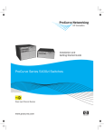
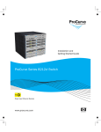
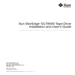
NetCommWireless
Quick Start Guide
3G M2M Router / Plus
NTC-6200 Series
NetCommWireless
Quick start guide
This quick start guide is designed to get you up and running quickly with your new
NTC-6200 Series router. More advanced set up instructions can be found in the
user guide which can be downloaded from
www.netcommwireless.com/product/m2m/ntc-6200.
Package contents
This package includes
| Wireless M2M
1.
2.
3.
4.
5.
6.
7.
8.
9.
2
1 x NetComm Wireless NTC-6200 Series router (NTC-6200-01 shown)
1 x Six-way terminal block (NTC-6200-01, NTC-6200-02, NTC-6200-11 and NTC-6200-12 only)
2 x 3G antennas
1 x DIN rail mounting bracket
1 x 1.5m Yellow Ethernet cable 8P8C
1 x Two-way terminal block (NTC-6200-03 and NTC-6200-13 only)
1 x Torx screw for SIM tray cover
1 x SIM tray cover
1 x Quick start guide (not shown)
NTC-6200 Series - 3G M2M Router / Plus
1
2
5
6
8
7
| Wireless M2M
4
3
3
NetCommWireless
Device overview
NTC-6200-01, NTC-6200-02, NTC-6200-11 and NTC-6200-12 models
ITEM
DESCRIPTION
1
SIM card slot
Insert SIM card here.
2
Six-way terminal
block connector
Connect power source, ignition and I/O wires here. Power, ignition
and I/O wires may be terminated on the supplied terminal block and
connected to a power source. Refer to the diagram and table under
Step 5 of the Installing your device section for correct wiring of the
terminal block. Operates in the 8-40V DC range.
3
Reset button
Press and hold for less than 5 seconds to reboot to normal mode.
Press and hold for 5 to 15 seconds to reboot to recovery mode.
| Wireless M2M
Press and hold for 15 to 20 seconds to reset the router to factory
default settings.
4
4
RJ45 PoE
Ethernet port
Connect one or several devices via a network switch here. This
port can also optionally receive Power over Ethernet (802.3af PoE)
in which case the DC power supply can serve as a backup power
source if required. (PoE available on NTC-6200-01 and NTC-620011 only).
5
Aux antenna
socket
SMA female connector for auxiliary antenna (receive diversity).
6
Mini USB 2.0
OTG port
Provides connectivity for optional external storage or a USB Ethernet
dongle. Supplies up to 0.5A to connected device.
7
GPS antenna
socket
SMA female connector for GPS antenna.
8
Serial port
Female DB9 port supporting 9-wire RS-232, RS-485 or RS-422
(software selectable).
9
Main antenna
socket
SMA female connector for main antenna.
NTC-6200 Series - 3G M2M Router / Plus
6
7
8
4
9
| Wireless M2M
5
3
2
1
5
NetCommWireless
Device overview
NTC-6200-03 and NTC-6200-13 models
ITEM
DESCRIPTION
1
SIM card slot
Insert SIM card here.
2
Two-way
terminal block
connector
Connect power source wires here. Power wires may be terminated
on the supplied terminal block and connected to a power source.
Refer to the diagram and table under Step 5 of the Installing your
device section for correct wiring of the terminal block.
Operates in the 8-40V DC range.
3
Reset button
Press and hold for less than 5 seconds to reboot to normal mode.
Press and hold for 5 to 15 seconds to reboot to recovery mode.
| Wireless M2M
Press and hold for 15 to 20 seconds to reset the router to factory
default settings.
6
4
RJ45 Ethernet
port
Connect one or several devices via a network switch here.
5
Aux antenna
socket
SMA female connector for auxiliary antenna (receive diversity).
6
Mini USB 2.0
OTG port
Provides connectivity for optional external storage or a USB Ethernet
dongle. Supplies up to 0.5A to connected device.
7
Serial port
Female DB9 port supporting 9-wire RS-232, RS-485 or RS-422
(software selectable).
8
Main antenna
socket
SMA female connector for main antenna.
NTC-6200 Series - 3G M2M Router / Plus
6
7
4
8
| Wireless M2M
5
3
2
1
7
NetCommWireless
Getting started
Depending on your individual setup, you may need certain components to
configure your device correctly.
External power supply unit for the NTC-6200 Series router (not included).
Flathead screwdriver for terminating power input wires.
Notebook or PC for advanced configuration.
Additional fasteners and screwdrivers for specific wall/rail mounting.
Mounting options
| Wireless M2M
The NetComm Wireless NTC-6200 Series router can be installed quickly and easily
in a variety of locations.
8
MOUNT TYPE
DESCRIPTION
BENEFITS
1
Wall mount
Flat against the wall
Slimline form factor, close
to wall
2
Wall mount via
DIN rail mounting
bracket
DIN Rail mounting bracket is secured to
the wall and the router is attached to the
mounting bracket.
Easy to remove
3
DIN rail mount
DIN Rail mounting bracket is slid or
snapped on to the DIN Rail and the router
is attached to the mounting bracket.
Simplicity, easy to
remove
4
Pole mount via
DIN rail mounting
bracket
DIN Rail mounting bracket is secured to a
pole or other fixed object using cable ties
and the router is attached to the mounting
bracket.
Easy to remove, flexibility
of orientation, variety
of objects to which the
router may be mounted.
5
Desk mount
Stand on a desk
Simplicity, versatility
NTC-6200 Series - 3G M2M Router / Plus
1.Wall mount
4. Pole mount using
DIN rail bracket
2.Wall mount via
DIN rail bracket
V Bend allows you to snap
the DIN bracket onto the
middle of a DIN rail rather
than sliding it onto the end.
5. Desk mount
| Wireless M2M
3.DIN rail mount
9
NetCommWireless
Overview of LED indicators
LED
ICON
NAME
Power
Network
GPS2 /
Customizable
LED Indicator
| Wireless M2M
Signal
strength
10
COLOR
STATE
DESCRIPTION
Off
Power off
Double flash
Powering up
On
Power on
On
Power on in recovery mode
Slow flashing
Hardware error
On
Connected via WWAN
Blinking1
Traffic via WWAN
Slow flashing
Connecting PDP
On
Registered network
Slow flashing
Registering network
Slow flashing
SIM PIN locked
Fast flashing
SIM PUK locked
On
Can’t connect
Off
GPS function disabled
On
GPS function is enabled but no
satellite is detected.
Flashing
Satellite detected, acquiring location.
On
Satellite detected, location acquired.
On
3G
On
2G GPRS
On
GSM only (no GPRS)
1 The term “blinking” means that the LED may pulse, with the intervals that the LED is on and off
not being equal. The term “flashing” means that the LED turns on and off at equal intervals.
2 GPS not available on NTC-6200-03 and NTC-6200-13.
NTC-6200 Series - 3G M2M Router / Plus
Installing your device
Step 1: Insert the SIM card
| Wireless M2M
Press the SIM Eject button to eject the SIM card tray. Place the SIM card in the
tray and then insert the loaded tray into the SIM slot with the gold side facing up,
as shown below.
11
NetCommWireless
Step 2: Fix the SIM tray cover to the device (optional)
If you wish to protect the SIM card from tampering, use a Torx screwdriver to fix
the SIM tray cover to the router with the supplied Torx screw.
Step 3: Attach the antennas
| Wireless M2M
The NTC-6200 Series router is shipped with caps on the Main, Auxiliary and on
the GPS antenna sockets for those models equipped with GPS. To attach the
supplied antennas, first remove the socket caps from the Main and Auxiliary
antenna sockets then screw the antennas onto the sockets by turning them
in a clockwise direction. Please refer to the Device overview section for the
antenna socket layout. If you have an NTC-6200 Series router with GPS and have
purchased a GPS antenna, remove the socket cap from the GPS antenna socket
and attach the antenna to the socket in the same manner.
12
NTC-6200 Series - 3G M2M Router / Plus
Step 4: Mount the router
Mount your router in a suitable location using the options listed in the Mounting
options section.
When selecting a location to mount the NTC-6200 Series router, keep in mind that
it features two high performance antennas designed to provide optimum signal
strength in a wide range of environments. If you find the signal strength is weak,
try moving the router to a different place, mounting it differently or changing the
orientation of the antennas.
| Wireless M2M
The signal strength LEDs update within a few seconds with a rolling average signal
strength reading. When selecting a location for the router, please allow up to 20
seconds for the signal strength LEDs to update before repositioning.
13
NetCommWireless
Step 5: Connect the power and Ethernet cables
Connect power to your router using one of the following options.
Power over Ethernet (802.3af PoE) (NTC-6200-01 & NTC-6200-11 only)
Connect your router to a PoE injector or PoE network switch using the bundled
yellow Ethernet cable 8P8C. This method uses the Ethernet connection to power
and transfer data to and from the router.
DC power via the six-way / two-way connector
Remove the attached green terminal block from your router and connect to the
router’s power socket using a DC power supply, sold separately.
DC power via field terminated power source
If an 8-40V DC power supply is available, you can insert the wires into the
supplied terminal block to power your router. Use a flathead screwdriver to tighten
the terminal block screws and secure the power wires, making sure that you have
correctly wired the terminal block as illustrated below.
TERMINAL
DESCRIPTION
+
Positive wire for power
-
Ground Wire
i
Dedicated terminal for ignition detection1
I/O
Three terminals used for input/output
detection (please refer to the User Guide)1
| Wireless M2M
1 - NTC-6200-01, NTC-6200-02, NTC-6200-11 and NTC-6200-12 models only
14
The green power LED on the router lights up when a power source is connected.
Tip: You can connect both the PoE and DC power sources at the same time. When both are
connected, the DC power acts as backup to the PoE input (PoE option available on the
NTC-6200-01 and NTC-6200-11 only).
NTC-6200 Series - 3G M2M Router / Plus
Attach the supplied yellow Ethernet cable 8P8C to the LAN Ethernet port on your
router and the other end to your computer.
Step 6: Access the router’s web interface
In your web browser’s address bar enter http://192.168.1.1/. The login page is
displayed.
There are two system management accounts (Root Manager and Admin) with different
management capabilities.
Root Manager account
Grants full privileges such as firmware upgrades, device configuration, backup
and restore, and reset to factory default settings. To access the Root Manager
account, use these login details.
http://192.168.1.1
Username
root
Password
admin
Admin account
Allows updates to general settings. To access the Admin account, use these
login details.
admin
Password
admin
Enter the username and password for the admin or root manager account and
click Log in. The Status page is displayed.
| Wireless M2M
http://192.168.1.1
Username
15
NetCommWireless
Step 7: Unlock the SIM Card
If the inserted SIM card is PIN locked, a pop-up window is displayed informing you
that you must unlock the SIM before use.
Click the OK button. The SIM Security page is displayed.
| Wireless M2M
In the Current PIN field, enter the SIM PIN and then enter it again in the Confirm
current PIN field. If you do not want to enter the PIN code each time the SIM
is inserted, select the Remember PIN option. Click the Save button. After a
moment, the router displays “Success! The SIM unlock was successful”.
16
NTC-6200 Series - 3G M2M Router / Plus
Step 8: Connect to the Internet
If the SIM Status is OK, the NTC-6200 Series router automatically attempts to
connect to the Internet by detecting the correct APN and connection details.
If automatic configuration was unsuccessful, you must manually enter the
connection details.
To manually configure the connection profile:
1. From the top menu bar, select the Networking option.
2. Next to Profile1, click the
screen is displayed.
button. The Data connection profile settings
3. Ensure that the Automatic APN selection toggle key is set to the
OFF position.
4. In the APN field, enter the APN name that your carrier requires for mobile
broadband connection. If required, enter the Username and Password in the
Username and Password fields. Click the Save button.
| Wireless M2M
The connection profile is now configured.
17
NetCommWireless
Verifying the connection status
| Wireless M2M
Click on the Status menu item from the top menu bar. The Status page is
displayed. The mobile broadband connection is established successfully if the
Status field in the WWAN connection status section displays Connected.
18
NTC-6200 Series - 3G M2M Router / Plus
Configuring multiple
devices
To apply your advanced configuration settings to more than one NTC-6200 Series
router, follow these simple steps.
Step 1
Back up your router’s configuration
Log in to the web configuration interface, click on the System menu, select
System configuration and click on Settings backup and restore.
| Wireless M2M
If you want to password protect your backup configuration files, enter your
password in the fields under Save a copy of current settings and click on
Save. If you don’t want to password protect your files, just click on Save.
The router will then prompt you to select a location to save the settings file.
19
NetCommWireless
Step 2
Restore your backup configuration
In the web configuration interface click on the System menu, select System
configuration and click on Settings backup and restore.
From the Restore saved settings section, click on Choose a file and select
the backup configuration file on your computer.
Click Restore to copy the settings to the new NTC-6200 Series router. The
router will apply these settings and inform you it will reboot - click on OK.
| Wireless M2M
Tip: Don’t change the file extension of the backup file as this may cause it to corrupt.
20
NTC-6200 Series - 3G M2M Router / Plus
Safety and product care
RF exposure
Your device contains a transmitter and a receiver. When it is on, it receives and transmits RF
energy. When you communicate with your device, the system handling your connection controls
the power level at which your device transmits.
This device meets the government’s requirements for exposure to radio waves.
This device is designed and manufactured not to exceed the emission limits for exposure
to radio frequency (RF) energy set by the Federal Communications Commission of the
U.S. Government.
This device complies with FCC radiation exposure limits set forth for an uncontrolled
environment. To ensure compliance with RF exposure guidelines the device must be used with a
minimum of 20cm separation from the body. Failure to observe these instructions could result in
your RF exposure exceeding the relevant guideline limits.
External antenna
Any optional external antenna used for this transmitter must be installed to provide a separation
distance of at least 20 cm from all persons and must not be co-located or operated in
conjunction with any other antenna or transmitter. Please consult the health and safety guide of
the chosen antenna for specific body separation guidelines as a greater distance of separation
may be required for high-gain antennas.
Any external antenna gain must meet RF exposure and maximum radiated output power limits
of the applicable rule section. The maximum antenna gain for this device as reported to the FCC
is: 0.2 dBi (850MHz) and 2.7 dBi (1900MHz).
CE approval (European Union)
manufacturer affixes the marking in order to be able to sell their product in the European
market. The wireless device is approved to be used in the member states of the EU. NetComm
Wireless declares that the wireless device is in compliance with the essential requirements
and other relevant provisions of the Radio and Telecommunications Terminal Equipment
Directive 1999/5/EC (R&TTE Directive). Compliance with this directive implies conformity to the
following European Norms – N 60950 – Product Safety, EN 301 489 EMC, EN301511 GSM
| Wireless M2M
This device has been tested to and conforms to the regulatory requirements of the European
Union and attained CE Marking. The CE Mark is a conformity marking consisting of the letters
“CE.” The CE Mark applies to the products regulated by the central European health, safety and
environmental protection legislation. The CE Mark is obligatory for products it applies to: the
21
NetCommWireless
RF, EN301908 UMTS RF, EN 62311 SAR Technical requirement for radio equipment. A notified
body has determined that this device has properly demonstrated that the requirements of the
directive have been met and has issued a favourable certificate of expert opinion. As such the
device will bear the notified body number 0682 after the CE mark.
The CE Marking is not a quality mark. Foremost, it refers to the safety rather than to the quality
of the product. Secondly, CE Marking is mandatory for the product it applies to whereas most
quality markings are voluntary.
Marking: The product shall bear the CE mark, the notified body
number(s) as depicted to the left. This product has also passed the
following certification standards –
Health (Article 3.1(a) of the R&TTE Directive)
EN 62311: 2008 ; EN 50385 :2002
Safety (Article 3.1(a) of the R&TTE Directive)
EN 60950-1:2006/A11:2009+A1:2010+A12:2011
Electromagnetic compatibility (Article 3.1 (b) of the R&TTE Directive)
EN 301 489-1 V1.9.2, EN 301 489-3 V1.4.1, EN 301 489-7 V1.3.1
EN 301 489-17 V2.2.1 (NTC-6200-01 and NTC-6200-11)
EN 301 489-24 V1.5.1
EN 55022:2010/ AC:2011 Class B, EN55024: 2010
EN 61000-3-2:2006/A1:2009/A2:2009, EN 61000-3-3:2008
Radio frequency spectrum usage (Article 3.2 of the R&TTE Directive)
EN 301 511 V9.0.2, EN 301 908-1 V5.2.1, EN 301 908-2 V5.2.1
EN 300 328 V1.8.1 (NTC-6200-01 and NTC-6200-11)
EN 300 440-1 V1.6.1, EN 300 440-2 V1.4.1
RoHS Directive (2011/65/EU)
EN 50581: 2012
| Wireless M2M
NOTE: To comply with the RF exposure requirements, this equipment must be operated with a
minimum of 20 cm separation from the user. This is a regulatory requirement and applies
to all 3G capable devices meeting standard regulatory compliance such as the compliance
standards listed above.
22
NTC-6200 Series - 3G M2M Router / Plus
FCC statement
FCC compliance
Federal Communications Commission Notice (United States): Before a wireless device model is
available for sale to the public, it must be tested and certified to the FCC that it does not exceed
the limit established by the government-adopted requirement for safe exposure.FCC regulations
FCC regulations
This device complies with part 15 of the FCC Rules. Operation is subject to the following two
conditions: (1) This device may not cause harmful interference, and (2) this device must accept
any interference received, including interference that may cause undesired operation.
This device has been tested and found to comply with the limits for a Class B digital device,
pursuant to Part 15 of the FCC Rules. These limits are designed to provide reasonable
protection against harmful interference in a residential installation. This equipment generates,
uses and can radiate radio frequency energy and, if not installed and used in accordance with
the instructions, may cause harmful interference to radio communications. However, there is no
guarantee that interference will not occur in a particular installation. If this equipment does cause
harmful interference to radio or television reception, which can be determined by turning the
equipment off and on, the user is encouraged to try to correct the interference by one or more
of the following measures:
| Wireless M2M
Reorientate or relocate the receiving antenna.
Increase the separation between the equipment and receiver.
Connect the equipment into an outlet on a circuit different from that to which the
receiver is connected.
Consult the dealer or an experienced radio/TV technician for help.
Changes or modifications not expressly approved by the party responsible for compliance could
void the user‘s authority to operate the equipment.
23
NetCommWireless
IC regulations
This device complies with Industry Canada licence-exempt RSS standard(s). Operation is
subject to the following two conditions:
(1) this device may not cause interference, and
(2) this device must accept any interference, including interference that may cause undesired
operation of the device.
Le présent appareil est conforme aux CNR d’Industrie Canada applicables aux appareils radio
exempts de licence. L’exploitation est autorisée aux deux conditions suivantes:
(1) l’appareil ne doit pas produire de brouillage, et
(2) l’utilisateur de l’appareil doit accepter tout brouillage radioélectrique subi, même si le
brouillage est susceptible d’en compromettre le fonctionnement.”
This Class B digital apparatus complies with Canadian ICES-003.
Cet appareil numérique de la classe B est conforme à la norme NMB-003 du Canada.
IMPORTANT NOTE:
IC radiation exposure statement:
This equipment complies with IC RSS-102 radiation exposure limits set forth for an
uncontrolled environment. This equipment should be installed and operated with minimum
distance 20cm between the radiator and the user’s body
Electrical safety
Accessories
Only use approved accessories.
Do not connect with incompatible products or accessories.
Connection to a car
Seek professional advice when connecting a device interface to the vehicle electrical system.
| Wireless M2M
Distraction
24
Operating machinery
Full attention must be given to operating the machinery in order to reduce the risk of an accident.
NTC-6200 Series - 3G M2M Router / Plus
Product handling
You alone are responsible for how you use your device and any consequences of its use.
You must always switch off your device wherever the use of a mobile phone is prohibited. Do
not use the device without the clip-on covers attached, and do not remove or change the
covers while using the device. Use of your device is subject to safety measures designed to
protect users and their environment.
Always treat your device and its accessories with care and keep it in a clean and dustfree place.
Do not expose your device or its accessories to open flames or lit tobacco products.
Arrange power and Ethernet cables in a manner such that they are not likely to be
stepped on or have items placed on them.
Ensure that the voltage and rated current of the power source match the requirements
of the device. Do not connect the device to an inappropriate power source.
| Wireless M2M
Do not expose your device or its accessories to liquid, moisture or high humidity.
Do not drop, throw or try to bend your device or its accessories.
Do not use harsh chemicals, cleaning solvents, or aerosols to clean the device or
its accessories.
Do not paint your device or its accessories.
Do not attempt to disassemble your device or its accessories, only authorised
personnel must do so.
Do not use or install this product in extremely hot or cold areas. Ensure that the
device is installed in an area where the temperature is within the supported operating
temperature range (-20°C to 70°C)
Do not use your device in an enclosed environment or where heat dissipation is
poor. Prolonged use in such space may cause excessive heat and raise ambient
temperature, which will lead to automatic shutdown of your device or the disconnection
of the mobile network connection for your safety. To use your device normally again
after such shutdown, cool it in a well-ventilated place before turning it on.
Please check local regulations for disposal of electronic products.
Do not operate the device where ventilation is restricted
Installation and configuration should be performed by trained personnel only.
Do not use or install this product near water to avoid fire or shock hazard. Avoid
exposing the equipment to rain or damp areas.
25
NetCommWireless
Children
Do not leave your device and its accessories within the reach of small children or allow them to
play with it. They could hurt themselves or others, or could accidentally damage the device.
Your device contains small parts with sharp edges that may cause an injury or which could
become detached and create a choking hazard.
Emergency situations
This device, like any wireless device, operates using radio signals, which cannot guarantee
connection in all conditions. Therefore, you must never rely solely on any wireless device for
emergency communications.
Device heating
Your device may become warm during normal use.
Faulty and damaged products
Do not attempt to disassemble the device or its accessories.
Only qualified personnel must service or repair the device or its accessories.
If your device or its accessories have been submerged in water punctured or subjected to a
severe fall, do not use until they have been checked at an authorised service centre.
Interference
Care must be taken when using the device in close proximity to personal medical devices, such
as pacemakers and hearing aids.
Pacemakers
Pacemaker manufacturers recommend that a minimum separation of 15cm be maintained
between a device and a pacemaker to avoid potential interference with the pacemaker.
Hearing aids
| Wireless M2M
People with hearing aids or other cochlear implants may experience interfering noises when
using wireless devices or when one is nearby.
26
The level of interference will depend on the type of hearing device and the distance from the
interference source, increasing the separation between them may reduce the interference. You
may also consult your hearing aid manufacturer to discuss alternatives.
Medical devices
Please consult your doctor and the device manufacturer to determine if operation of your device
may interfere with the operation of your medical device.
NTC-6200 Series - 3G M2M Router / Plus
Hospitals
Switch off your wireless device when requested to do so in hospitals, clinics or health care facilities.
These requests are designed to prevent possible interference with sensitive medical equipment.
Interference in cars
Please note that because of possible interference to electronic equipment, some vehicle
manufacturers forbid the use of devices in their vehicles unless an external antenna is included
in the installation.
Explosive environments
Petrol stations and explosive atmospheres
In locations with potentially explosive atmospheres, obey all posted signs to turn off wireless
devices such as your device or other radio equipment. Areas with potentially explosive
atmospheres include fuelling areas, below decks on boats, fuel or chemical transfer or storage
facilities, areas where the air contains chemicals or particles, such as grain, dust, or metal powders.
Blasting caps and areas
| Wireless M2M
Turn off your device or wireless device when in a blasting area or in areas posted turn off “twoway radios” or “electronic devices” to avoid interfering with blasting operations.
27
Product Warranty
For warranty information please visit
http://www.netcommwireless.com/product/m2m/ntc-6200
Technical Support
For firmware updates or if you have any technical difficulties with your product,
please refer to the support section of our website.
support.netcommwireless.com
QSG-00054 rev2
NETCOMM WIRELESS LIMITED ABN 85 002 490 486
Head Office, 18-20 Orion Road
Lane Cove, Sydney, NSW 2066, Australia
p: +61 2 8205 3888
f: +61 2 9424 2010
e:[email protected]
www.netcommwireless.com