1
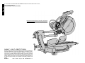
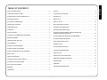
DEWALT Industrial Tool Company, 626 Hanover Pike, P.O. Box 158, Hampstead, MD 21074
DW708
Printed in U.S.A.
Copyright © 1997
(JUL97-CD-1)
Form No. 384133-01
INSTRUCTION MANUAL
GUIDE D'UTILISATION
MANUAL DE INSTRUCCIONES
INSTRUCTIVO DE OPERACIÓN, CENTROS DE SERVICIO Y PÓLIZA
DE GARANTÍA. ADVERTENCIA: LÉASE ESTE INSTRUCTIVO ANTES
DE USAR EL PRODUCTO.
DW708 Sliding Compound Miter Saw
DW708 Scie à onglets mixtes coulissants
DW708 Sierra de ángulo compuesto (ingleteadora) corrediza
IF YOU HAVE ANY QUESTIONS OR COMMENTS ABOUT THIS OR ANY DEWALT TOOL,
CALL US TOLL FREE AT:
English
1-800-4-DEWALT (1-800-433-9258)
This product is covered under U.S. Patent No. 5,199,343 and
other patents pending.
DEWALT… BUILT JOBSITE TOUGH
D E WALT high performance industrial tools are made for America’s
toughest industrial and construction applications. The design of every
tool in the line – from drills to sanders to grinders – is the result of
rigorous use on jobsites and throughout industry. Each tool is produced
with painstaking precision using advanced manufacturing systems and
intense quality control. Every tool is checked before it leaves the factory
to make sure that it meets your standards for durability, reliability and
power.
D E WALT
Built Jobsite Tough…WE GUARANTEE IT.
SAFETY INSTRUCTIONS ............................................................................................2
SWITCH ........................................................................................................................9
ADDITIONAL SAFETY RULES.....................................................................................2
CUTTING WITH YOUR SAW .......................................................................................9
DOUBLE INSULATION/POLARIZED PLUG.................................................................2
CROSSCUTS................................................................................................................9
EXTENSION CORDS ...................................................................................................2
BEVEL CUTS ................................................................................................................9
ELECTRICAL CONNECTION .......................................................................................4
QUALITY OF CUT ......................................................................................................10
UNPACKING YOUR SAW ............................................................................................4
BODY AND HAND POSITION ....................................................................................10
FAMILIARIZATION .......................................................................................................4
CLAMPING THE WORKPIECE ..................................................................................10
CONTROLS ..................................................................................................................4
SUPPORT FOR LONG PIECES .................................................................................10
SPECIFICATIONS ........................................................................................................4
CUTTING PICTURE FRAMES, SHADOW BOXES AND
OTHER FOUR SIDED PROJECTS ............................................................................10
OPTIONAL ATTACHMENTS/ACCESSORIES .............................................................5
CUTTING TRIM MOULDING AND OTHER FRAMES ................................................11
BENCH MOUNTING .....................................................................................................6
CUTTING COMPOUND MITERS ...............................................................................11
TRANSPORTING THE SAW ........................................................................................7
DUAL RANGE MITER SCALE ....................................................................................11
ADJUSTMENTS............................................................................................................7
VERNIER SCALE ......................................................................................................11
MITER SCALE ADJUSTMENT .....................................................................................7
CUTTING BASE MOLDINGS .....................................................................................12
MITER POINTER ADJUSTMENT .................................................................................7
CUTTING CROWN MOLDING ...................................................................................13
MITER LOCK/DETENT ROD ADJUSTMENT...............................................................7
SPECIAL CUTS ..........................................................................................................15
BEVEL STOP ...............................................................................................................8
INSTALLING A NEW SAW BLADE ............................................................................15
FENCE ADJUSTMENT .................................................................................................8
REMOVING AND REPLACING BELT ........................................................................16
GUARD ACTUATION AND VISIBILITY ........................................................................9
MAINTENANCE ..........................................................................................................16
AUTOMATIC ELECTRIC BRAKE .................................................................................9
WARRANTY................................................................................................................16
RAIL GUIDE ADJUSTMENT.........................................................................................9
TROUBLE SHOOTING GUIDE...................................................................................17
BRUSHES .....................................................................................................................9
OPERATION .................................................................................................................9
1
English
TABLE OF CONTENTS
English
IMPORTANT SAFETY INSTRUCTIONS (FOR ALL TOOLS)
WARNING: For your own safety read instruction manual before operating sliding
compound miter saw.
WARNING: When using electric tools, basic safety precautions should always be
followed to reduce risk of fire, electric shock, and personal injury, including the following:
Double Insulation
Double insulated tools are constructed throughout with two separate layers of electrical
insulation or one double thickness of insulation between you and the tool’s electrical system.
Tools built with this insulation system are not intended to be grounded. As a result, your
tool is equipped with a two prong plug which permits you to use extension cords without
concern for maintaining a ground connection.
NOTE: Double insulation does not take the place of normal safety precautions when
operating this tool. The insulation system is for added protection against injury resulting from
a possible electrical insulation failure within the tool.
•
CAUTION: WHEN SERVICING USE ONLY IDENTICAL REPLACEMENT PARTS.
Repair or replace damaged cords.
•
•
Polarized Plugs
•
•
To reduce the risk of electric shock, this equipment has a polarized plug (one blade is wider
than the other). This plug will fit in a polarized outlet only one way. If the plug does not fit fully
into the outlet, reverse the plug. If it still does not fit, contact a qualified electrician to install
the proper outlet. Do not change the plug in any way.
•
•
Important Safety Instructions
•
• KEEP GUARDS IN PLACE and in working order.
• REMOVE ADJUSTING KEYS AND WRENCHES. Form habit of checking to see that keys
and adjusting wrenches are removed from tool before turning it on.
• KEEP WORK AREA CLEAN. Cluttered areas and benches invite injuries.
• DON’T USE IN DANGEROUS ENVIRONMENT. Don’t use power tools in damp or wet
locations, or expose them to rain. Keep work area well lighted.
• KEEP CHILDREN AWAY. All visitors should be kept safe distance from work area.
• MAKE WORKSHOP KID PROOF with padlocks, master switches, or by removing starter
keys.
• DON’T FORCE TOOL. It will do the job better and safer at the rate for which it was
designed.
• USE RIGHT TOOL. Don’t force tool or attachment to do a job for which it was not designed.
• USE PROPER EXTENSION CORD. Make sure your extension cord is in good condition.
When using an extension cord, be sure to use one heavy enough to carry the current your
product will draw. An undersized cord will cause a drop in line voltage resulting in loss of
power and overheating. The following table shows the correct size to use depending on
cord length and nameplate ampere rating. If in doubt, use the next heavier gage. The
smaller the gage number, the heavier the cord.
•
•
•
Minimum Gage for Cord Sets
Volts
Total Length of Cord in Feet
120V
0-25
26-50
51-100
101-150
240V
0-50
51-100
101-200
201-300
Ampere Rating
More Not more
AWG
Than Than
0
- 6
18
16
16
14
6
- 10
18
16
14
12
10 - 12
16
16
14
12
12 - 16
14
12
Not Recommended
WEAR PROPER APPAREL. Do not wear loose clothing, gloves, neckties, rings, bracelets,
or other jewelry which may get caught in moving parts. Nonslip footwear is recommended.
Wear protective hair covering to contain long hair.
ALWAYS USE SAFETY GLASSES. Also use face or dust mask if cutting operation is
dusty. Everyday eyeglasses only have impact resistant lenses, they are not safety glasses.
DON’T OVERREACH. Keep proper footing and balance at all times.
MAINTAIN TOOLS WITH CARE. Keep tools sharp and clean for best and safest
performance. Follow instructions for lubricating and changing accessories.
DISCONNECT TOOLS before servicing; when changing accessories, such as blades, bits,
cutters, and the like.
REDUCE THE RISK OF UNINTENTIONAL STARTING. Make sure switch is in off position
before plugging in.
USE RECOMMENDED ACCESSORIES. Consult the instruction manual for
recommended accessories. The use of improper accessories may cause risk of injury to
persons.
NEVER STAND ON TOOL. Serious injury could occur if the tool is tipped or if the cutting
tool is unintentionally contacted.
CHECK DAMAGED PARTS. Before further use of the tool, a guard or other part that is
damaged should be carefully checked to determine that it will operate properly and perform
its intended function–check for alignment of moving parts, binding of moving parts,
breakage of parts, mounting, and any other conditions that may affect its operation. A guard
or other part that is damaged should be properly repaired or replaced.
NEVER LEAVE TOOL RUNNING UNATTENDED. TURN POWER OFF. Don’t leave tool
until it comes to a complete stop.
REPLACEMENT PARTS. When servicing, use only identical replacement parts.
Additional Safety Rules for Sliding Compound Miter
Saw
• Wear eye protection.
• Keep hands out of path of saw blade. NEVER CUT A PIECE WHERE HAND WOULD BE
6" (152 mm) OR LESS FROM BLADE.
• Do not operate saw without guards in place.
• Do not perform any operation freehand.
• Never reach in back of saw blade.
• Turn off tool and wait for saw blade to stop before moving workpiece or changing settings.
• Disconnect power before changing blade or servicing.
• Blade adjustment is to be made only with the power off and the blade stopped.
• Never use saw without kerf plate.
• Replace kerf plate when kerf exceeds blade width by 1/8" (3 mm).
• To reduce risk of injury, return carriage to the full rear position after each crosscut
operation.
2
CAUTION: FAILURE TO HEED THESE WARNINGS MAY RESULT IN PERSONAL
INJURY AND SERIOUS DAMAGE TO THE SAW.
• DO-Protect electric supply line with at least a 15 ampere time-delay fuse or a circuit
breaker.
• DO-Make certain the blade rotates in the correct direction and that the teeth at the bottom
of the blade are pointing to the rear of the sliding compound miter saw.
• DO use stablizer bars at all times.
• DO-Be sure all clamp handles and knobs are tight before starting any operation.
• DO-Be sure all blade and clamp washers are clean and recessed sides of collars are
against blade. Tighten arbor screw securely.
• DO- Keep saw blade sharp and properly set.
• DO-Keep motor air slots free of chips and dirt.
• DO-Use blade guards at all times.
• DO-Keep hands out of path of saw blade.
• DO-Shut off power, disconnect cord from power source and wait for saw blade to stop
before servicing or adjusting tool.
• DO-Support long work with an outboard tool rest.
• DON’T-Attempt to operate on anything but designated voltage.
• DON’T-Operate unless all clamp handles are tight.
• DON’T- Use blades larger or smaller than those which are recommended.
• DON’T- Wedge anything against fan to hold motor shaft.
• DON’T-Force cutting action. (Stalling or partial stalling of motor can cause major damage.
Allow motor to reach full speed before cutting.)
• DON’T- Cut ferrous metals (Those with any iron or steel content) or any masonry.
• DON’T-Use abrasive wheels. The excessive heat and abrasive particles generated by
them will damage the saw.
• DON’T use any abrasive blades.
• DON’T-Allow anyone to stand behind saw.
• DON’T-Apply lubricants to the blade when it’s running.
• DON’T-Place either hand in the blade area when the saw is connected to the power source.
• DON’T-Use blades rated less than 4800 R.P.M.
• DON’T-Attempt to cut small pieces 6" (152mm) without clamping.
• DON’T-Operate saw without guards in place.
• DON’T-Perform any operation freehand.
• DON’T-Reach around or behind saw blade.
• DON’T-Place hands closer than 6 inches from the saw blade.
• DON’T - Reach underneath the saw unless it is turned off and unplugged.
• DON’T - Move either hand from saw or workpiece or raise arm until blade has stopped.
CAUTION: Do not connect unit to electrical power source until complete instructions
are read and understood.
• ON MOTOR HOUSING:
WARNING:
FOR YOUR OWN SAFETY, READ INSTRUCTION MANUAL
BEFORE OPERATING MITER SAW.
ALWAYS WEAR EYE PROTECTION.
DOUBLE INSULATED. WHEN SERVICING, USE ONLY IDENTICAL REPLACEMENT
PARTS.
DO NOT EXPOSE TO RAIN OR USE IN DAMP LOCATIONS.
• ON MOVING FENCE:
ALWAYS ADJUST FENCE PROPERLY BEFORE USE. CLAMP SMALL PIECES
BEFORE CUTTING. SEE MANUAL.
• ON GUARD:
DANGER – KEEP AWAY FROM BLADE.
• ON ARBOR COVER:
WARNING:
FOR YOUR OWN SAFETY READ INSTRUCTION MANUAL BEFORE OPERATING
MITER SAW.
KEEP HANDS OUT OF PATH OF SAW BLADE.
DO NOT OPERATE SAW WITHOUT GUARDS IN PLACE.
ALWAYS TIGHTEN ADJUSTMENT KNOBS BEFORE USE.
DO NOT PERFORM ANY OPERATION FREEHAND.
NEVER REACH IN BACK OF SAW BLADE.
NEVER CROSS ARMS IN FRONT OF BLADE.
TURN OFF TOOL AND WAIT FOR SAW BLADE TO STOP BEFORE MOVING
WORKPIECE, CHANGING SETTINGS OR MOVING HANDS.
DISCONNECT POWER BEFORE CHANGING BLADE OR SERVICING.
TO REDUCE THE RISK OF INJURY, RETURN CARRIAGE TO THE FULL REAR
POSITION AFTER EACH CROSSCUT OPERATION.
REAR STABILIZER BARS MUST BE IN PLACE DURING USE.
THINK! YOU CAN PREVENT ACCIDENTS.
CAUTION: Some wood contains preservatives such as copper chromium arsenate
(CCA) which can be toxic. When cutting these materials extra care should be taken to
avoid inhalation and minimize skin contact.
• ON BASE:
• ON STABILIZERS:
REAR STABILIZER BARS MUST BE IN PLACE DURING USE
3
English
For your convenience and safety, the following warning labels are on your sliding
compound miter saw.
•
English
Electrical Connection
Be sure your power supply agrees with the nameplate
marking. AC ONLY means that your saw will operate on
alternating current only. A voltage decrease of 10 percent
or more will cause a loss of power and overheating. All
DeWalt tools are factory tested. If this tool does not
operate, check the power supply.
Unpacking Your Saw
Check the contents of your sliding compound miter saw
carton to make sure that you have received all parts. In
addition to this instruction manual, the carton should
contain:
1. One No. DW708 sliding compound miter saw.
2. One No. 340984-20, 60 tooth
DEWALT 12" (305mm) dia. saw blade
3. One blade wrench in wrench pocket shown in Figure 2
4. Two base stabilizers
Familiarization
Your sliding compound miter saw is fully assembled
(except for the stabilizers) in the carton. Open the box and
lift the saw out by the lifting handle and the rail, as shown in
Figure 1.
Place the saw on a smooth, flat surface such as a
workbench or strong table.
Examine Figures 2 & 3 to become familiar with the saw and
its various parts. The following section on adjustments will
refer to these terms and you must know what and where
the parts are.
Press down lightly on the operating handle and pull out the
lock down pin, as shown in Figure 4. Gently release the
downward pressure and allow the arm to rise to its full
height.
BEVEL STOP
The bevel adjustment/lock handle (Figure 2) allows you to
bevel your saw 48° left or right (Figure 13). To loosen the
lever and adjust the bevel setting, turn the handle
counterclockwise,the saw head bevels easily to the left or
right. To tighten, turn the handle clockwise. Bevel degree
markings are on the bottom rear of the saw arm.
BEVEL STOP OVERRIDE
The bevel stop override (Figure 2) allows you to override
the built-in bevel stop at 0˚.
The saw will automatically stop at 0˚ when brought up from
the left. To move past 0˚ to the right, press the bevel stop
override. The saw will automatically stop at 45˚ on the left
or right.
BEVEL STOP PINS
The bevel stop pins (Figure 2) allow you to override built-in
bevel stops at 0° and 45° left and right.
Each bevel stop pin has two positions: engaged and
disengaged. When the 0° (middle) bevel stop pin is
engaged, the saw will stop at 0° when brought up from the
left. To move past 0° to the right, disengage the bevel stop
pin. To disengage:
• Bevel saw at least 5° away from stop
• Push stop pin in completely and rotate it 90°
COUNTERCLOCKWISE until it stops.
• Release bevel stop pin and allow it to spring outward to
its disengaged position.
To reset the 0° bevel stop, re-engage the bevel stop pin. To
re-engage:
• Bevel saw at least 5° away from stop
• Push stop pin in completely and rotate it 90°
CLOCKWISE until it stops.
• Release bevel stop pin and allow it to spring outward to
its engaged position.
NOTE: Saw will not adjust from a right bevel position to
a left bevel position with the 0° (middle) bevel stop pin
engaged.
The bevel stop pins at 45° left and right stop position can be
disengaged to 48° following the procedure above.
RAIL LOCK KNOB
The rail lock knob (Figure 2) allows you to lock the saw
head firmly to keep it from sliding on the rails. This is
necessary when making certain adjustments or when
transporting the saw.
GROOVING STOP
The grooving stop allows for groove cutting.
Flipping the grooving lever toward the front of the saw and
adjusting the thumbscrew changes the depth of the groove
cut. Flipping the lever toward the rear of the saw bypasses
this feature.
MOVABLE FENCE ADJUSTMENT KNOBS
The fence adjustment knobs allow adjustment of the left or
right fence. Loosen the plastic adjustment knob (behind the
fence) and slide the fence in or out. Retighten before
operating the saw.
Specifications
CAPACITY OF CUT
50° miter left, 60° miter right
48 degree bevel left and right
Miter Bevel Max
Max
Height
Width
____ _____ ______
_____
0°
0°
45 L&R° 0°
0°
45° L
0°
45° R
Controls
Your sliding compound miter saw has several main
controls, which will be discussed briefly here. For more
information on these controls, see the respective sections
later in the manual.
FIG. 1
FIG. 1A
MITER CONTROL
The miter lock/adjustment lever and trigger allows you to
miter your saw 50° left and 60° right. To miter the saw, lift
the miter lock/adjustment lever, squeeze the detent trigger
(Figure 2) and set the miter angle desired on the miter scale
(Figure 2). Push down on the miter lock lever to lock the
saw table in-place.
TRIGGER SWITCH
The trigger switch (Figure 3) turns your saw on and off. A
hole is provided in the trigger for insertion of a padlock to
lock the saw off.
4
4.7"
4.7"
3.2"
1.7"
12"
8.5"
12"
12"
FIG. 2
OPERATING HANDLE
FIG. 3A
BRUSH INSPECTION CAP
English
BLADE GUARD
DUST SPOUT
ARBOR COVER
RAILS
BLADE WRENCH
LOCK DOWN PIN
BEVEL STOP PIN:
ENGAGED
BEVEL STOP PIN:
DISENGAGED
FENCE
FIG. 3B
BEVEL STOP PIN
MITER ADJUSTMENT/LOCK
LEVER
BEVEL
ADJUSTMENT/LOCK
HANDLE
DETENT
TRIGGER
TABLE
BEVEL STOP:
ENGAGED
BEVEL STOP :
DISENGAGED
BASE STABILIZER
MITER SCALE
BASE
FIG. 3
LIFTING
HANDLE
BELT COVER SCREW
TRIGGER SWITCH
BELT COVER
SPINDLE LOCK BUTTON
RAIL LOCK KNOB
THUMBSCREW
GROOVING STOP
KERF PLATE
FENCE ADJUSTMENT
KNOB (NOT SHOWN)
DRIVE
120 Volt Motor
1700 Watts
13 Amp Motor
4000 RPM
Cut Helical Gears with Roller Bearings
Multi-V Belt
60 Tooth Carbide Blade
Automatic Electric Brake
Optional Attachments/Accessories
WARNING: For safe operation, read instruction
literature included with attachments/accessories.
Extension Kit: DW7080
Used to support long overhanging workpieces, the work
support is user assembled. Your saw table is designed to
accept two work supports; one on each side. One set
stores conveniently under the saw table.
Adjustable Length Stop: DW7051
Requires the use of one work support (see above). It is
used to make repetitive cuts of the same length from 0 to
42" (0 to 106cm).
Material Clamp: DW7082
Used for firmly clamping workpiece to the saw table for
precision cutting.
Crown Stop: DW7084
Used for precision cutting of crown molding.
BENCH MOUNTING HOLES
HAND HOLDS
5
English
Dust Bag: DW7053
Equipped with a zipper for easy emptying.
NOTE: Spout has a provision to attach a vacuum hose to
collect sawdust. Proper orientation of dust bag is necessary
to avoid interference during operation of saw. If interference
cannot be avoided, dust bag must be removed. ALWAYS
MAKE A DRY RUN WITHOUT POWER BEFORE MAKING
ANY CUTS.
Kit Box: DW7056
Used to store and transport DW708 accessories.
SAW BLADES: ALWAYS USE 12" (305mm) SAW
BLADES. SPEED RATING MUST BE AT LEAST 4800
RPM. USE OF SMALLER DIAMETER BLADES MAY
CAUSE SEVERE DAMAGE TO SAW.
Application
Blade
No. of
Type
Descript.
Teeth
of Cut
Fine Trim
Precision
60-100
Very
Molding
Ground
Smooth
Carbide
Splinter
Free
Trim, Framing,
Combination
32-60
Smooth
Pressure
Multi-Purpose
Fast Cut
Treated
Decking
Aluminum
Non-Ferrous
60-80
—
Metal Cutting
Negative Rake Teeth
FIG. 4
FIG. 6
LOCK
DOWN PIN
FIG.5
Stabilizers
Your saw includes two base stabilizers. These must be
installed before using your saw. Insert the stabilizers into
the holes in the back of the unit, as shown in Figure 5.
Move the stabilizers in or out until they contact the work
surface. Then tighten the screws in the base to fasten the
stabilizers.
SCREW
FIG. 7
Bench Mounting
Holes are provided to facilitate bench mounting, as shown
in Figure 3. (Two different sized holes are provided to
accommodate different sizes of screws. Use either hole, it
is not necessary to use both.) Always mount your saw
firmly to prevent movement. To enhance the tool’s
portability, it can be mounted to a piece of 1/2" (12.7mm) or
thicker plywood which can then be clamped to your work
support or moved to other job sites and reclamped.
NOTE: If you elect to mount your saw to a piece of
plywood, make sure that the mounting screws don’t
protrude from the bottom of the wood. The plywood must sit
flush on the work support. When clamping the saw to any
work surface, clamp only on the clamping bosses where
the mounting screw holes are located. Clamping at any
other point will interfere with the proper operation of the
saw.
BACK OF SAW
STABILIZER
SCREW
6
FIG. 8
FIG. 10
Transporting the Saw
MITER
LOCK/DETENT
ROD
LOWER RIGHT
BEVEL STOP PIN
TURN OFF AND UNPLUG THE SLIDING COMPOUND
MITER SAW BEFORE ATTEMPTING TO MOVE IT OR
MAKE ANY ADJUSTMENTS.
Use the lock down pin when carrying the saw from one
place to another. The lock down pin is not to be used for
any cutting operation, and is for carrying and storage only.
When transporting the saw, always lock the head in the
down position, miter the saw fully to the right (60° miter),
lock the miter adjustment/lock lever, lock the rail lock knob
with the head fully forward, slide the fences completely
inward, and lock the bevel adjustment/lock lever with the
saw at a 0° bevel. Always use the carrying hand holds in
the base to transport the saw. Carry the saw as shown in
Figure 1A.
Adjustments
FIG. 9
PERFORM ALL ADJUSTMENTS WITH THE SLIDING
COMPOUND MITER SAW UNPLUGGED.
NOTE: Your sliding compound miter saw is fully and
accurately adjusted at the factory at the time of
manufacture. If readjustment due to shipping and handling
or any other reason is required, follow the steps below to
adjust your saw.
Once made, these adjustments should remain accurate.
FIG. 11
MITER SCALE ADJUSTMENT
Place a square against the saw’s base, fence and blade, as
shown in Figure 6. (Do not touch the tips of the blade teeth
with the square. To do so will cause an inaccurate
measurement.) Lift the miter clamp lever and swing the miter
arm until the miter latch locks it at the 0 miter position. If the
saw blade is not exactly perpendicular to the fence, loosen
the four screws that hold the miter scale to the base (shown
in Figure 9) and move the scale/miter arm assembly left or
right until the blade is perpendicular to the fence, as
measured with the square. Retighten the four screws. Pay
no attention to the reading of the miter pointer at this point.
MITER POINTER ADJUSTMENT
Lift the miter adjustment/lock lever and move the miter arm
to the zero position, as shown in Figure 7. With the miter
adjustment/lock lever loose allow the miter latch to snap
into place as you rotate the miter arm to zero. Observe the
pointer and miter scale. If the pointer does not indicate
exactly zero, loosen the screw that holds the pointer in
place and gently move the pointer left or right. Retighten
the screw after setting the pointer to zero.
MITER SCALE SCREW
7
English
CAUTION: To prevent binding and inaccuracy, be sure
the mounting surface is not warped or otherwise uneven. If
the saw rocks on the surface place a thin piece of material
under one saw foot until the saw sits firmly on the mounting
surface.
English
MITER LOCK/DETENT ROD ADJUSTMENT
The miter lock/detent rod should be adjusted if the base of
the saw can be moved when the miter adjustment/lock
lever is locked-down.
To adjust the miter lock/detent rod, put the miter
adjustment/lock lever in the up, unlocked position. Using a
slotted screwdriver, tighten the lock rod by turning it
clockwise (Figure 8). Turn the lock rod until it is tight, then
turn counterclockwise 1/4 turn. To ensure the lock lever is
functioning properly, re-lock the miter lock to a non-detented
measurement on the miter scale—for example, 34°—and
ensure the table will not rotate.
BEVEL STOPS AND POINTER ADJUSTMENT
Adjusting the bevel stop and pointer to 0°
Place the saw in the up position (0° bevel). Push head fully
back (toward fence) and lock the rail lock knob. Place a
square against the saw’s base, fence and blade (Figure 11).
(Do not touch the tips of the blade teeth with the square. To
do so will cause an inaccurate measurement.) Loosen the
bevel lock handle so bevel movement is snug, but not fully
loose.
Push head of saw to the right (to contact the 0° bevel stop).
The 0° bevel stop pin must be in its engaged position (Fig.
3A). Adjust the right bevel stop pin (Figure 12) until the blade
is perpendicular to the base of the saw. Tighten the bevel
lock handle securely. Make sure the bevel pointer indicates
0° exactly. If if does not, loosen the screw that holds the
pointer in place, and gently move the pointer left or right.
Retighten the screw after setting the pointer to 0°.
RIGHT BEVEL
STOP PIN
FIG. 12
FIG. 14
LEFT BEVEL STOP
PIN
FENCE
FIG. 13
FIG. 15
Adjusting the bevel stop to 45° left or right
NOTE: Adjust the 45° bevel angles only after performing the
0° bevel angle adjustment and with the 45° bevel stop pins
engaged (Fig. 3A).
To adjust the left 45° bevel angle, loosen the bevel lock
handle and tilt the head to the left until it is resting on the 45°
bevel stop pin. If the pointer does not indicate exactly 45°,
turn the left bevel stop pin until the pointer reads 45°.
To adjust the right 45° bevel angle, loosen the bevel lock
handle and tilt the head to the right until it is resting on the 45°
bevel stop pin. If the pointer does not indicate exactly 45°,
turn the lower right bevel stop pin until the pointer indicates
45° (Figure 10).
FENCE ADJUSTMENT
Turn Off and Unplug the Miter Saw
To adjust the left or right fence, loosen the plastic knob
shown in Figure 15 and slide the fence in or out. Always
adjust the fence to be as close to the blade as practical to
provide maximum workpiece support, without interfering with
arm up & down movement or guard movement. Tighten
knobs securely.
NOTE: When beveling to the right, it may be necessary to
remove the right fence. To remove the fence, loosen the
fence adjustment knob until the fence is free to slide off.
ALWAYS make a trial run with the power off to ensure your
saw will cut safely and properly.
FENCE
ADJUSTMENT
KNOB
BEVEL STOP
BEVEL LOCK
HANDLE
8
FIG. 16
AUTOMATIC ELECTRIC BRAKE
Your saw is equipped with an electric blade brake which
stops the saw blade in approximately 3 seconds after
trigger release. This is automatic and requires no
adjustment.
Occasionally, under certain conditions, the brake will not
function properly and won’t stop the saw in the 3 seconds
as discussed above. If this condition occurs, turn the saw
on and off four or five times. If the brake still does not stop
the blade in about 3 seconds, the problem may be worn
brushes. Replace the brushes as described below and try
the saw again. If the problem still persists, have the tool
serviced at a Black & Decker service center or company
authorized service facility.
FIG. 17
RAIL GUIDE ADJUSTMENT
Periodically check the rails for any play or clearance. The
top rail can be adjusted with the two right set screws shown
in Figure 16. To reduce clearance, rotate the set screws
clockwise gradually while sliding the saw head back and
forth. Reduce play while maintaining minimum sliding force.
Brushes
TRIGGER SWITCH
HOLE FOR PADLOCK
DISCONNECT PLUG FROM POWER SUPPLY
Inspect carbon brushes regularly by unplugging tool,
removing the brush inspection cap (Figure 2) and
withdrawing the brush assembly. Keep brushes clean and
sliding freely in their guides. Always replace a used brush in
the same orientation in the holder as it was prior to its
removal. Carbon brushes have varying symbols stamped
into their sides, and if the brush is worn down to the line
closest to the spring, they must be replaced. Use only
identical DEWALT brushes. Use of the correct grade of
brush is essential for proper operation of electric brake. New
brush assemblies are available at Black & Decker service
centers. The tool should be allowed to “run in” (run at no
load) for 10 minutes before use to seat new brushes. The
electric brake may be erratic in operation until the brushes
are properly seated (worn in).
9
While “running in” DO NOT TIE, TAPE, OR OTHERWISE
LOCK THE TRIGGER SWITCH ON. HOLD BY HAND
ONLY.
Operation
Plug the saw into 60 Hz power source. Be sure the cord will
not interfere with your work.
SWITCH
To turn the saw on, depress the trigger switch as shown in
Figure 17. To turn the tool off, release the switch. There is
no provision for locking the switch on, but a hole is provided
in the trigger for insertion of a padlock to lock the saw off.
CUTTING WITH YOUR SAW
NOTE: Although this saw will cut wood and many nonferrous materials, we will limit our discussion to the cutting
of wood only. The same guidelines apply to the other
materials. DO NOT CUT FERROUS (IRON AND STEEL)
MATERIALS OR MASONRY WITH THIS SAW. Do not
use any abrasive blades.
CROSSCUTS
A crosscut is made by cutting wood across the grain at any
angle. A straight crosscut is made with the miter arm at the
zero degree position. Set and lock the miter arm at zero,
hold the wood firmly on the table and against the fence.
With the rail lock knob tightened, turn on the saw by
squeezing the trigger switch as shown in Figure 17.
When the saw comes up to speed (about 1 second) lower
the arm smoothly and slowly to cut through the wood. Let
the blade come to a full stop before raising arm.
When cutting anything larger than 2x4, use an out-downback motion. Pull the saw out, toward you, lower the saw
head down toward the workpiece, and push the saw back
to complete the cut. Do not allow the saw to contact the
top of the workpiece while pulling out. The saw may run
toward you, causing personal injury or damage to the
workpiece.
NOTE: The rail lock knob (Figure 3) must be loose to allow
the saw to slide along its rails.
Miter crosscuts are made with the miter arm at some angle
other than zero. This angle is often 45 degrees for making
corners, but can be set anywhere from 50° left to 60° right.
After selecting the desired miter angle, be sure to lockdown the miter adjustment/lock lever. Make the cut as
described above.
NOTE: Cutting of multiple pieces is not recommended, but
can be done safely by ensuring that each piece is held
firmly against the table and fence.
BEVEL CUTS
A bevel cut is a crosscut made with the saw blade at a
bevel to the wood. In order to set the bevel, unlock the
bevel adjustment/lock lever and move the saw to the left or
right as desired. Once the desired bevel angle has been
set, lock the bevel adjustment/lock lever firmly.
English
SET SCREWS
GUARD ACTUATION AND VISIBILITY
The blade guard on your saw has been designed to
automatically raise when the arm is brought down and to
lower over the blade when the arm is raised.
The guard can be raised by hand when installing or
removing saw blades or for inspection of the saw. NEVER
RAISE THE BLADE GUARD MANUALLY UNLESS THE
SAW IS TURNED OFF.
NOTE: Certain special cuts will require that you manually
raise the guard.
The front section of the guard is louvered for visibility while
cutting. Although the louvers dramatically reduce flying
debris, they are openings in the guard and safety glasses
should be worn at all times when viewing through the
louvers.
English
The bevel stop pins (Figure 2) allow you to override built-in
bevel stops at 0° and 45° left and right. See page 4 for
more information.
Bevel angles can be set from 48° left to 48° right and can
be cut with the miter arm set between 50° left and 60°
right. Ensure the fence has been adjusted properly.
FIG. 18
QUALITY OF CUT
The smoothness of any cut depends on a number of
variables. Things like material being cut, blade type, blade
sharpness and rate of cut all contribute to the quality of the
cut.
When smoothest cuts are desired for molding and other
precision work, a sharp (60 tooth carbide) blade and a
slower, even cutting rate will produce the desired results.
To ensure that material does not creep while cutting, clamp
it securely in place. Always let the blade come to a full stop
before raising the arm.If small fibers of wood still split out
at the rear of the workpiece, stick a piece of masking tape
on the wood where the cut will be made. Saw through the
tape and carefully remove tape when finished.
For varied cutting applications, refer to the list of
recommended saw blades for your saw and select the one
that best fits your needs.
CORRECT
CORRECT
BODY AND HAND POSITION (See Figure 18)
Proper positioning of your body and hands when operating
the sliding compound miter saw will make cutting easier,
more accurate and safer. Never place hands near cutting
area. Place hands no closer than 6" (152mm) from the
blade. Hold the workpiece tightly to the table and the fence
when cutting. Keep hands in position until the trigger has
been released and the blade has completely stopped.
ALWAYS MAKE DRY RUNS (UNPOWERED) BEFORE
FINISH CUTS SO THAT YOU CAN CHECK THE PATH
OF THE BLADE. DO NOT CROSS HANDS.
Keep both feet firmly on the floor and maintain proper
balance. As you move the miter arm left and right, follow it
and stand slightly to the side of the saw blade. Sight
through the guard louvers when following a pencil line.
CLAMPING THE WORKPIECE
TURN OFF AND UNPLUG SAW
ALWAYS CLAMP WOOD TO THE SAW WHEN
POSSIBLE. You can clamp to either side of the saw and
remember to position your clamp against a solid, flat
surface of the base. For best results use the DW7082
material clamp made for use with your saw. Available from
your dealer at extra cost.
When cutting small pieces requiring your hand to be
dangerously close (within 6" (152mm) to the saw blade, a
clamp MUST be used to prevent loss of control. The left or
right fence may be adjusted to aid clamping.
INCORRECT
SUPPORT FOR LONG PIECES
Turn Off and Unplug Saw
ALWAYS SUPPORT LONG PIECES
For best results, use the DW7080 extension kit to extend
the table width of your saw. Available from your dealer at
extra cost. Support long workpieces using any convenient
means such as sawhorses or similar devices to keep the
ends from dropping. The base top is 3.5" tall, allowing a 4x4
or 2 2x4s to be used on a long table or bench.
CUTTING PICTURE FRAMES, SHADOW BOXES AND
OTHER FOUR SIDED PROJECTS
10
INCORRECT
To best understand how to make the items listed here, we
suggest that you try a few simple projects using scrap wood
until you develop a FEEL for your saw.
Your saw is the perfect tool for mitering corners like the one
shown in Figure 19. Sketch A in Figure 19 shows a joint
made by using the bevel adjustment to bevel the edges of
the two boards at 45 degrees each to produce a 90 degree
corner. For this joint the miter arm was locked in the zero
position and the bevel adjustment was locked at 45
degrees. The wood was positioned with the broad flat side
against the table and the narrow edge against the fence.
FIG. 19
A.
FIG. 22
DUAL RANGE MITER
SCALE
FIG. 20
DUAL RANGE MITER SCALE
The miter scale has two ranges of numbers for
convenience, as shown in Figure 22. One scale indicates 0
degrees when the blade is square to the fence. At this
position the other scale reads 90 degrees.
The 0 degree scale (larger numbers closer to the front edge)
is used when calculating angles. To calculate the proper
miter angle, divide 180 degrees by the number of sides of
the box or frame.
The 90 degree scale (smaller numbers behind the zero
degree scale) is used when a corner of your box or frame is
measured with a protractor. For example: if you measure
the corner of an 8 sided box, the protractor will read 135
degrees. To determine the proper miter setting, divide the
measured angle by two. The proper miter setting in this
example is 67-1/2 degrees. Set this angle on the 90 degree
scale. This is most useful when a corner is at an odd angle.
FIG. 21
ANGLE “A”
FIG. 23
DIAMOND SHAPED
CENTER MARK
The cut could also be made by mitering right and left with
the broad surface against the fence.
CUTTING TRIM MOLDING AND OTHER FRAMES
Sketch B in Figure 19 shows a joint made by setting the
miter arm at 45 degrees to miter the two boards to form a
90 degree corner. To make this type of joint, set the bevel
adjustment to zero and the miter arm to 45 degrees. Once
again, position the wood with the broad flat side on the
table and the narrow edge against the fence.
The two sketches in Figure 19 are for four sided objects
only.
As the number of sides changes, so do the miter and bevel
angles. The following chart gives the proper angles for a
variety of shapes.
(The chart assumes that all sides are of equal length.) For
a shape that is not shown in the chart, use the following
formula. 180 degrees divided by the number of sides
equals the miter or bevel angle.
- EXAMPLES NO. SIDES
4
5
6
7
ANGLE MITER OR BEVEL
45°
36°
30°
25.7°
FIG. 24
8
9
10
22.5°
20°
18°
CUTTING COMPOUND MITERS
A compound miter is a cut made using a miter angle and a
bevel angle at the same time. This is the type of cut used to
make frames or boxes with slanting sides like the one
shown in Figure 20.
NOTE: If the cutting angle varies from cut to cut, check
that the bevel adjustment/lock lever and the miter
adjustment/lock lever are securely tightened. These levers
11
VERNIER SCALE
Your saw is equipped with a vernier scale for added
precision. The vernier scale allows you to accurately set
miter
angles
to
the
nearest
1/4
degree
(15 minutes). To use the vernier scale follow the steps listed
below.
(As an example, assume that the angle you want to miter is
24-1/4 degree right).
1. Turn off sliding compound miter saw.
2. Set the miter angle to the nearest whole degree desired
by aligning the diamond-shaped center mark in the
vernier scale, shown in Figure 23, with the whole degree
number etched in the miter scale. Examine Figure 24
closely; the setting shown is 24 degrees right miter.
3. To set the additional 1/4 degree, move the first mark on
the RIGHT of the diamond to the RIGHT until the 1/4
degree vernier mark aligns with the CLOSEST degree
English
must be tightened and locked after making any changes in
bevel or miter.
The chart shown on page 14 will assist you in selecting the
proper bevel and miter settings for common compound
miter cuts. To use the chart, select the desired angle “A”
(Figure 21) of your project and locate that angle on the
appropriate arc in the chart. From that point follow the chart
straight down to find the correct bevel angle and straight
across to find the correct miter angle.
Set your saw to the prescribed angles and make a few trial
cuts. Practice fitting the cut pieces together until you
develop a feel for this procedure and feel comfortable with it.
Example: To make a 4 sided box with 25° exterior angles
(Angle A, Figure 21), use the upper right arc. Find 25° on the
arc scale. Follow the horizontal intersecting line to either
side to get miter angle setting on saw (23°). Likewise, follow
the vertical intersecting line to the top or bottom to get the
bevel angle setting on the saw (40°). Always try cuts on a
few scrap pieces of wood to verify settings on saw.
B.
English
mark on the miter scale. In our example, the closest
degree mark on the miter scale happens to be 25
degrees. Figure 24 shows a setting of 24-1/4 degrees
right miter.
4. To set a 1/2 degree, align the second mark on the scale
(marked 0.5) with the nearest whole degree number. For
example, to miter 24-1/2 degrees to the right, move the
SECOND mark on the RIGHT of the diamond to the
RIGHT until the 1/2 degree vernier mark aligns with the
CLOSEST degree mark on the miter scale.
5. To set a 3/4 degree, align the THIRD mark on the scale
with the nearest whole degree number. For example, to
miter 24-3/4 degrees to the right, move the THIRD
mark on the RIGHT of the diamond to the RIGHT until
the 3/4 degree vernier mark aligns with the CLOSEST
degree mark on the miter scale.
WHEN MITERING TO THE RIGHT
To increase the miter angle when mitering to the right,
move the arm to align the appropriate vernier mark with
the closest mark on the miter scale to the right. To
decrease the miter angle when mitering to the right, move
the arm to align the appropriate vernier mark with the
closest mark on the miter scale to the left.
FIG. 25
FIG. 27
FIG. 26
WHEN MITERING TO THE LEFT
To increase the miter angle when mitering to the left, move
the arm to align the appropriate vernier mark with the
closest mark on the miter scale to the left. To decrease the
miter angle when mitering to the left, move the arm to align
the appropriate vernier mark with the closest mark on the
miter scale to the right.
FIG. 28
CUTTING BASE MOLDING
ALWAYS MAKE A DRY RUN WITHOUT POWER
BEFORE MAKING ANY CUTS.
Straight 90 degree cuts –
Position the wood against the fence and hold it tightly to the
fence and table, as shown in Figure 25. Turn on the saw,
allow the blade to reach full speed and lower the arm
smoothly through the cut.
CUTTING BASE MOLDING UP TO 4-1/4" (108 mm)
HIGH VERTICALLY AGAINST THE FENCE
Position molding as shown in Figure 26.
All cuts made with the back of the molding against the
fence and bottom of the molding against the base.
INSIDE CORNER:
Left side
1. Miter left 45°
2. Save left side of cut
Right side
1. Miter Right 45°
2. Save right side of cut
OUTSIDE CORNER:
12
FIG. 29
TABLE
CROWN MOLDING FLAT ON TABLE AND AGAINST FENCE
FIG. 30
TOP SIDE
OF MOLDING
TABLE
BOTTOM
SIDE OF
MOLDING
CROWN MOLDING BETWEEN FENCE AND TABLE
FIG. 31
BLADE
FENCE
RIGHT
CUTTING 4-1/4"– 5-1/4" (108mm-133mm) BASE
MOLDING VERTICALLY AGAINST THE FENCE
• Position molding as shown in Figure 26.
• All cuts made with the back of the molding against the
fence
INSIDE CORNER:
Left side
1. Position molding with bottom of molding against the
base of the saw
2. Miter left 45°
3. Save left side of cut
Right side
1. Position molding with top of the molding resting on the
base of the saw
2. Miter left 45°
3. Save left side of cut
OUTSIDE CORNER:
Left side
1. Position molding with bottom of molding against the
base of the saw
2. Miter right 45°
3. Save left side of cut
NOTE: If the cut must be made somewhere other than 1"
(25.4mm) from the end of the molding: cut off the molding at
90° approx. 1" (25.4mm) longer than your final length then
make the miter cut as described above.
13
Right side
1. Position molding with bottom of the molding against the
base of the saw
2. Miter left 45°
3. Save the right side of cut
A third method of making the cut necessary
for sketch A is to make a zero degree miter,
45 degree bevel cut. Your saw can cut a bevel 12"
(305mm) wide.
CUTTING BASE MOLDING LAYING FLAT AND USING
THE BEVEL FEATURE
• All cuts made with the saw set at 45° bevel and
0 miter
• All cuts made with back of molding laying flat on the saw
and the bottom of the molding against the fence, as
shown in Figure 28.
INSIDE CORNER:
Left side
1. Bevel 45° right
2. Save right side of cut
Right side
1. Bevel 45° left
2. Save left side of cut
OUTSIDE CORNER:
Left side
1. Bevel 45° left
2. Save right side of cut
Right side
1. Bevel 45° right
2. Save left side of cut
CUTTING CROWN MOLDING
To fit properly, crown molding must be cut with extreme
accuracy.
The two flat surfaces on a given piece of crown molding are
at angles that, when added together, equal exactly 90
degrees. Most, but not all, crown molding has a top rear
angle (the section that fits flat against the ceiling) of 52
degrees and a bottom rear angle (the part that fits flat
against the wall) of 38 degrees.
Your sliding compound miter saw has special pre-set miter
latch points at 31.6 degrees left and right for cutting crown
molding flat at the proper angle. There is also a mark on the
bevel scale at 33.9 degrees.
The chart on the next page gives the proper settings for
cutting crown molding. (The numbers for the miter and
bevel settings are very precise and are not easy to
accurately set on your saw.) Since most rooms do not have
angles of precisely 90 degrees, you will have to fine tune
your settings anyway.
English
FENCE
Left side
1. Miter right at 45°
2. Save left side of cut
Right side
1. Miter left at 45°
2. Save right side of cut
Material up to 4.25" (108mm) can be cut as described
above. For wider boards [up to 5.25" (133mm)] several
minor concessions must be made.
When cutting a board between 4.25" (108mm) and 5.25"
(133mm) in width the roller on the tip of the guard will hang
up on the workpiece. If this occurs, roll the guard up just
enough to clear the workpiece , as shown in Figure 27.
Once you have cleared the workpiece, you can release the
guard and it will continue to open as the cut progresses.
Hold the workpiece securely against the fence and base
before starting the cut.
When mitering to the right side of a base molding wider
than 3.9" (99mm) standing vertically against the fence as
in Figure 27, the saw can only cut through the board up to
1 inch from the end of the board. Trying to cut more than
an inch will cause the saw’s gear case to interfere with the
workpiece. If you want to cut base molding between 41/4" (108mm) and 5-1/4" (133mm) wide vertically follow
the directions below.
INSTRUCTIONS FOR CUTTING CROWN MOLDING LAYING FLAT AND USING THE COMPOUND
FEATURES
1. Molding laying with broad back surface down flat
on saw table (See Figure 26)
2. The settings below are for All Standard (U.S.)
crown molding with 52° and 38° angles.
English
TABLE 1 COMPOUND MITER CUT (POSITION WOOD WITH BROAD FLAT SIDE ON THE TABLE
AND THE NARROW EDGE AGAINST THE FENCE)
5
10
15
•
20
25
30
35
ANGLE OF SIDE OF BOX (ANGLE A)
X
BO
50
55
5
10
15
20
60
ED
D
SI
6-
25
30
35
40
20
25
45
35
40
45
70
50
X
BO
MITER DEGREE SETTING
30
65
X
BO
5 10
15
D
DE
SI
8-
SET THIS MITER ANGLE ON SAW
45
BEVEL
SETTING
E
AR
U
SQ
40
50
55
55
60
75
65
60
70
80
65
75
70
75
80
BEVEL DEGREE SETTING
85
80
85
85
TYPE OF CUT
LEFT SIDE,INSIDE CORNER:
1. Top of molding against fence
2. Miter table set right 31.62°
3. Save left end of cut
RIGHT SIDE, INSIDE CORNER:
Right 33.9°
1. Top of molding against fence
2. Miter table set left 31.62°
3. Save right end of cut
LEFT SIDE, OUTSIDE CORNER:
Right 33.9°
1. Top of molding against fence
2. Miter table set left 31.62°
3. Save left end of cut
RIGHT SIDE, OUTSIDE CORNER:
Left 33.9°
1. Top of molding against fence
2. Miter table set right 31.62°
3. Save right end of cut
When setting bevel and miter angles for all compound
miters, remember that:
The angles presented for crown moldings are very
precise and difficult to set exactly. Since they can
easily shift slightly and very few rooms have exactly
square corners, all settings should be tested on scrap
molding.
Left 33.9°
PRETESTING WITH SCRAP MATERIAL IS
EXTREMELY IMPORTANT!
SET THIS BEVEL ANGLE ON SAW
14
FIG. 32
FENCE
FIG. 33
FIG. 34
WRONG
INSTRUCTIONS FOR CUTTING CROWN MOLDING
ANGLED BETWEEN THE FENCE AND BASE OF THE
SAW FOR ALL CUTS:
1. Angle the molding so the bottom of the molding (part which
goes against the wall when installed) is against the fence
and the top of the molding is resting on the base of the
saw, as shown in Figure 30.
2. The angled “flats” on the back of the molding must rest
squarely on the fence and base of the saw.
INSIDE CORNER:
Left side
1. Miter right at 45°
2. Save the right side of cut
Right side
1. Miter left at 45°
2. Save left side of cut
OUTSIDE CORNER:
Left side
1. Miter left at 45°
2. Save right side of cut
Right side
1. Miter right at 45°
2. Save left side of cut
SPECIAL CUTS
NEVER MAKE ANY CUT WITHOUT FIRMLY
CLAMPING THE MATERIAL.
Aluminum Cutting:
Aluminum extrusions such as those used when making
aluminum screens and storm windows can easily be cut
with your saw. Position the material so that you will be
cutting the thinnest cross section, as shown in Figure 31.
Figure 32 illustrates the wrong way to cut these extrusions.
Use a wax lubricant when cutting aluminum such as
Johnson’s Stick Wax No. 140. Apply the stick wax directly
to the saw blade before cutting. Never apply stick wax to a
15
moving blade.
The wax, available at most hardware stores and industrial
mill supply houses, provides proper lubrication and keeps
chips from adhering to the blade.
Bowed Material:
When cutting bowed material always position it
as shown in Figure 33 and never like that shown in Figure
34. Positioning the material incorrectly will cause it to pinch
the blade near the completion of the cut.
Cutting Plastic Pipe and Other Round Cross-Sectional
Material
Plastic pipe and similar material can be easily cut with
your saw. It should be cut just like wood and CLAMPED
OR HELD FIRMLY TO THE FENCE TO KEEP IT FROM
ROLLING PARTICULARLY WHEN CUTTING ANGLES.
Cutting Large Material
Occasionally you will encounter a piece of wood a little too
large to fit beneath the blade guard. A little extra height
can be gained by rolling the guard up out of the way, as
shown in Figure 27. Avoid doing this as much as possible,
but if need be, the saw will operate properly and make the
bigger cut. NEVER TIE, TAPE, OR OTHERWISE HOLD
THE GUARD OPEN WHEN OPERATING THIS SAW.
GROOVING
Your sliding compound miter saw is equipped with a
grooving lever and thumbscrew to allow for groove cutting.
To use the grooving feature, flip the grooving lever toward
the front of the saw, as shown in Figure 35.
Adjust the thumbscrew to change the depth of the groove
cut. ALWAYS MAKE DRY RUNS (UNPOWERED)
BEFORE FINISH CUTS SO THAT YOU CAN CHECK THE
DEPTH OF THE BLADE.
NOTE: Your saw is not designed for use with dado blades.
Installing a New Saw Blade
UNPLUG THE SLIDING COMPOUND MITER SAW
DO NOT CUT FERROUS METAL (THAT WITH AN IRON
OR STEEL CONTENT) OR MASONRY WITH THIS
SLIDING COMPOUND MITER SAW.
Before installing or removing a blade, always lock the
miter adjustment/lock lever, lock the rail lock knob, and lock
the bevel adjustment/lock lever.
1) Loosen the arbor cover screw, and pivot the arbor
cover up, as shown in Figure 36. NOTE: This screw is a
specific length to provide a caliper for the blade to
prevent guard damage. Do not replace this screw with
a different screw.
2) While holding the spindle lock, use the supplied blade
wrench to loosen (clockwise) the left hand threaded
blade screw.
NOTE: To use the spindle lock (Figure 37), depress the
button as shown and rotate the blade by hand until you
English
BLADE
PRETESTING WITH SCRAP MATERIAL IS
EXTREMELY IMPORTANT!
METHOD FOR CUTTING CROWN MOLDING ANGLED
BETWEEN THE FENCE AND TABLE
Place the molding on the table at an angle between the
fence and the saw table, as shown in Figure 29. Use of the
crown molding fence accessory (DW7054) is highly
recommended because of its degree of accuracy and
convenience. The crown molding fence accessory is
available at extra cost from your local dealer.
The advantage to cutting crown molding using this method
is that no bevel cut is required. Minute changes in the
miter angle can be made without affecting the bevel angle.
This way, when corners other than 90 degrees are
encountered, the saw can be quickly and easily adjusted
for them. Use the crown molding fence accessory to
maintain the angle at which the molding will be on the wall.
feel the lock engage. Continue to hold the lock button in to
keep the spindle from turning.
3) Using the blade wrench, remove the blade screw and
carefully remove the blade.
The inner clamp washer is installed first, then the blade
adapter. The blade adapter is designed to permit the use of
saw blades with 1" (25.4mm) arbor holes as well as those
with 5/8" (15.8mm) arbor holes.
When using blades with 1" (25.4mm) arbor holes, install the
blade adapter over the spindle shaft and against the inner
clamp washer. Next, install the saw blade making sure
that the arbor hole in the blade fits on the blade adapter.
Make sure that the teeth at the bottom of the blade are
pointing toward the back of the saw (away from the
operator). Install the outer clamp washer and install the
blade screw. Tighten firmly using the spindle lock and the
provided wrench (left hand threads). When using saw
blades with 5/8" (15.8mm) arbor holes, remove the blade
adapter! Save it in a safe place for future use. The rest of
the blade assembly is exactly the same.
REPLACE AND SECURE ARBOR COVER TO PREVENT
BLADE SCREW AND BLADE SEPARATION FROM
SPINDLE SHAFT.
English
THUMBSCREW
GROOVING LEVER
FIG. 35
FIG. 37
SPINDLE
LOCK
SET
SCREW
SCREWS
NEVER DEPRESS THE SPINDLE LOCK PIN WHILE
THE BLADE IS ROTATING.
Removing and Replacing Belt
The belt is designed to last the life of the tool. However,
abuse of the tool could cause the belt to fail.
If the blade does not turn when the motor is running, the
belt has failed. To inspect or replace the belt, remove the
belt cover screw. Remove the belt cover. Inspect the ribs of
the belt for wear or failure. Check belt tension by squeezing
the belt as shown in Figure 38. The belt should contact the
center boss with medium pressure.
To adjust the tension, loosen, but do not remove, the six
Phillips head screws (Figure 38). Then rotate the set
screw on the top of the motor plate casting until the proper
tension is achieved. Tighten the six screws securely and
replace the belt cover. NOTE: Overtightening the belt will
cause premature motor failure.
FIG. 38
FIG. 36
Maintenance
CENTER BOSS
16
1. All bearings are sealed ball bearings. They are
lubricated for life and need no further maintenance. Do
not use WD-40 or any other lubricant.
2. Periodically clean all dust and wood chips from around
the area of the saw. Even though slots are provided to
allow debris to pass through, some dust will accumulate.
3. The brushes are designed to give you several years of
use. If they ever need replacement follow the
instructions on page 9 or return the tool to the nearest
service center for repair. Service center locations are
packed with your tool.
Trouble Shooting Guide
Important
Full Warranty
DEWALT heavy duty industrial tools are warranted for one
year from date of purchase. We will repair, without charge,
any defects due to faulty materials or workmanship. Please
return the complete unit to any DEWALT certified service
center. This warranty does not apply to accessories or
damage caused where repairs have been made or
attempted by others.
In addition to the warranty, DEWALT tools are covered by
our:
30 DAY NO RISK SATISFACTION GUARANTEE
If you are not completely satisfied with the performance of
this tool within 30 days of purchase simply return it to your
place of purchase to replace it with a new identical tool.
BE SURE TO FOLLOW SAFETY RULES AND INSTRUCTIONS
TROUBLE! SAW WILL NOT START
WHAT’S WRONG?
WHAT TO DO…
1. Saw not plugged in
1. Plug in saw.
2. Fuse blown or circuit breaker tripped
2. Replace fuse or reset circuit breaker
3. Cord damaged
3. Have cord replaced by authorized service center
4. Brushes worn out
4. Have brushes replaced by authorized service
center.
TROUBLE! SAW MAKES UNSATISFACTORY CUTS
WHAT’S WRONG?
1. Dull blade
2. Blade mounted backwards
3. Gum or pitch on blade
4. Incorrect blade for work being done
WHAT TO DO…
1. Replace blade. See page 15.
2. Turn blade around. See page 15
3. Remove blade and clean with turpentine and
coarse steel wool or household oven cleaner.
4. Change the blade. See page 15.
TROUBLE! BLADE DOES NOT COME UP TO SPEED
WHAT’S WRONG?
1. Extension cord too light or too long
2. Low house current
WHAT TO DO…
1. Replace with adequate size cord. See page 2.
2. Contact your electric company
TROUBLE! MACHINE VIBRATES EXCESSIVELY
WHAT’S WRONG?
1. Saw not mounted securely to stand or work bench
2. Stand or bench on uneven floor
3. Damaged saw blade
WHAT TO DO…
1. Tighten all mounting hardware. See page 6.
2. Reposition on flat level surface. See page 6.
3. Replace blade. See page 15.
TROUBLE! DOES NOT MAKE ACCURATE MITER CUTS
WHAT’S WRONG?
1. Miter scale not adjusted correctly
2. Blade is not square to fence
3. Blade is not perpendicular to table
4. Workpiece moving
TROUBLE! MATERIAL PINCHES BLADE
WHAT’S WRONG?
1. Cutting bowed material
See ‘Tools-Electric’
–Yellow Pages–
for Service & Sales
17
WHAT TO DO…
1. Check and adjust. See page 7.
2. Check and adjust. See page 7.
3. Check and adjust fence. See page 8.
4. Clamp workpiece to fence or glue 120 grit
sandpaper to fence with rubber cement.
WHAT TO DO…
1. Position bowed material as shown on page 15.
English
To assure product SAFETY and RELIABILITY, repairs,
maintenance and adjustment (including brush inspection
and replacement) should be performed by authorized
service centers or other qualified service organizations,
always using identical replacement parts.
Black & Decker (U.S.) Inc. industrial tool service centers
are certified for servicing DEWALT industrial tools.