1
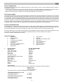
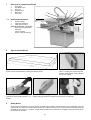
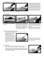
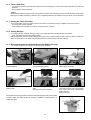
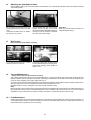
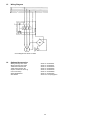
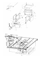
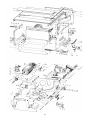
®
Betriebs- und Montageanleitung
Präzisionskreissäge
D
ENG
F
NL
Operating Instructions Precision Circular Saw
Notice de service et de montage Scie circulaire
de précision
Handleiding Bediening
Precisie-cirkelzaagmachine
115 115 9270 / D/ENG/F/NL / 3100 - 3.1
PK 300 K
Untergestell nicht im Lieferumfang enthalten (Sonderzubehör)
Base not included in Standard Delivery (Optional Accessoires)
Le châssis n’est pas compris dans le programme de livraison (équipement optionnel)
Het onderstel wordt niet standaard meegeleverd (beschikbaar als optie).
D
ENG
F
NL
Achtung!
Attention!
Attention!
Attentie!
Lesen Sie diese Anleitung vor der Installation und Inbetriebnahme aufmerksam durch.
Carefully read through these instructions prior to installation and commissioning.
Prière de lire attentivement la présente notice avant l'installation et la mise en service.
Lees deze instructies voor de installatie en ingebruikname aandachtig door.
ENG
Scope of Application
This Elektra Precision Circular Saw is designed to perform rip and crosscuts in wood or wooden materials having a square or
rectangular cross section.
- Crosscuts should be performed only with the help of a mitre fence or the Sliding Carriage PK, available as optional accessory.
- Do not crosscut round stock, for ripping use the Square and Round Stock Jig available as optional accessory.
- Maximum saw blade diameter is 300 mm, the minimum blade diameter must be 250 mm.
User Responsibility
This machine will perform in conformity with the description contained tin the instructions provided. This machine must be checked
periodically. Defective equipment (including power cable) should not be used. Parts that are broken, missing, plainly worn, distorted
or contaminated, should be replaced immediately. Should such repair or replacement become necessary, it is recommended that
such repairs are carried out be qualified persons approved by Elektra Beckum or its representative. This machine or any of its parts
should not be altered or changed from standard specifications. The user of this machine shall have the sole responsibility for any
malfunction which results from improper use or unauthorized modification from standard specification, faulty maintenance, damage
or improper repair by anyone other than qualified persons approved by Elektra Beckum or its representative.
Product Liability/Warranty
We explicitly draw your attention to the fact that, under the current product liability regulations, Elektra Beckum does not have to
assume liability for any damages causes by its products, if such damages result from improper repair, use of replacement parts other
than genuine Elektra parts, or repairs not having been carried out by customer service or authorized service centres.
The three-phase motor of this machine is equipped with an automatically engaging mechanical motor brake, designed for a long
service life. If the braking action fades, and the time to standstill exceeds 10 sec, the brake has to be replaced.
Consult your dealer or authorized service centre.
Table of Contents
1
2
3
4
5
6
7
8
9
1
Specifications
Standard Delivery
Installation
Connection to Power Mains
Controls/Settings
Saw Blades
Overview of Components/Terms
Jigs and Push Blocks
Safety Rules
10
11
12
13
14
15
16
17
Dust Collection
Operation
Adjusting the Saw Blade Position
Belt Tension
Care and Maintenance
Wiring Diagrams
Optional Accessories
Spare Parts Lists
Specifications
PK 300 K/4200 DNB
Saw table size
Table working height
Dept of cut at 90°/45°
Motor speed
Arbor speed
Main blade diameter
Cutting speed with Ø 300 mm blade
Motor capacity P1
Motor voltage
Mains frequency
Mains fuse
Suction port diameter
Weight
Stock-no.
710x900 mm
940 mm
104/70 mm
2800 rpm
3800 rpm
300 mm
60 mtr/sec
4200 W3 ~ 400 V
50/60 Hz
3 x 16 A time-lag
100 mm
90 kg
010 300 4209
Noise Emission
The noise emission levels shown below have been established by measuring methods according to:
DIN EN 23 746;
DIN EN 31 202;
ISO 7960 appendix A.
The correction factor K3 has been established by DIN EN 31204.
1. PK 300 K operating under no load
A-sound pressure level LpA
A-sound power level LWA
74,3 dB(A)
87,8 dB(A)
2. PK 300 K operating under load
A-sound pressure level LpA
A-sound power level LWA
84,7 dB(A)
98,2 dB(A)
16
2
Standard Delivery
Saw blade TCT 300x2.6/1.8x30 mm 28 alternate bevel teeth
Riving knife 2.5 mm
Saw blade guard
Rip fence
Mitre fence
Dust extraction port with hoses
Push stick
Tool set
Operating instructions
3
Installation
Place machine upside down on two battens to install the workstand. Do not tighten screws fully before all parts have been
installed.
Install suction port to chip case.
Use 3 each
hex. head screw M 6x16
serrated lock washer Ø 6.4
hex. nut M 6
Place spiral hose Ø 100 mm onto suction
port and secure with hose clamp Ø 100
mm. Install both side panels, using 4 each
hex. head screw M 6x16
serrated lock washer Ø 6.4
hex. nut M 6
Install rear panel (with hole) between the
side panels.
Use 6 each
hex. head screw M 6x16
serrated lock washer Ø 6.4
hex. nut M 6
Install dust collection port into hole of the
rear panel with 3 each
hex. head screw M 6x16
serrated lock washer Ø 6.4
hex. nut M 6
Place the spiral hose on the dust collection port and secure in place with the
second hose clamp Ø 100 mm.
Install the workstand's front panel.
Use 6 each
hex. head screw M 6x16
serrated lock washer Ø 6.4
hex. nut M 6
Put a hex. nut M 10 on the threaded bolt
of all 4 adjustable feet.
Install feet into tapped bushes M 10 located on each corner.
Now tighten all screw joints fully, then
stand machine on its feet. Place side
panels lids into the panel openings.
17
Loosely attach 2 carriage bolts M 6x16 to hose carrier, then slide hose carrier into the
rear T-groove of the table.
Raise saw blade (see paragraph 5) and
attach saw blade guard to riving knife.
Install spiral hose between saw blade guard and dust collection port.
3.1
Rip Fence Scale Adjustment
The rip fence scale is adjustable to accommodate saw blades of different widths.
Set rip fence against the blade. Loosen scale fixing screw and set scale until zero
mark matches the hairline of the fence bracket's magnifying glass. Tighten fixing
screw and verify setting by making a trial cut on a piece of scrap.
Note: The scale's zero mark and the hairline of the magnifying glass can only
line up with the fence extrusion installed in the upright position (wide edge facing
the blade).
3.2
Magnifying Class
The magnifying glass can be removed
from the rip fence for cleaning.
4
3.3
Rip Fence Adjustment
The rip fence is factory set parallel with the
saw blade. If adjustment is necessary
loosen the four screws holding the fence
extrusion to the carrier and set square
with the table.
3.4
Mitre Fence Adjustments
Both left and right hand 45° end stops are
factory set. If required the positions can
be adjusted with the setting screws. The
angle scale is also adjustable.
Connection to Power Mains
- This machine must be operated on a residual current operated device of 30 mA capacity, having a fault current breaker.
- This machine must be safety earthed. The yellow/green lead is the earth conductor.
- Fit plug matching your local standard outlet to the power cable.
- The outlet this machine is connected to must be earthed and phase protected by a 16 A time-lag fuse or circuit breaker.
- Do not operate saw with a damaged power cable. Risk of electrical shock.
Worn or defective cables must be replaced immediately. Have replaced by a qualified electrician only.
Check if voltage of power mains matches with voltage stated on machine's type plate.
For mains connection a 5-lead power cable is required. The yellow/green lead is the earth conductor. Do not connect the
yellow/green earth lead to any of the current conducting terminals. If in doubt-consult a qualified electrician.
Extension cables should have a minimum lead cross section of 1.5 mm2 and a rubber outer jacket (HO7RNF/SJT or similar).
Use of extension cables with too small a lead cross section causes a voltage drop and possible damage to motor and/or switch.
Important! Always disconnect from power before servicing the saw.
Direction of rotation of the saw blade is clockwise, when looking at it from the left side of the saw. To check start saw briefly.
If the blade runs counter-clockwise on a three-phase machine, have a qualified electrician interchange two of the phases to
correct.
Note: Wrong direction of rotation of the saw blade is dangerous and may cause severe personal injury.
18
4.1
Switch/Overload Protection
The switch is equipped with a no-volt release solenoid (magnetic switch), to
prevent start-up after a power failure. If the saw is not connected to the power
mains the switch does not engage. In the event of a power failure the machine
has to be restarted. In case of an overload of the main motor the build-in motor
protection relay trips and cuts the power to the motor. If the motor is shut off
repeatedly by the overload relay, check machine (motor brake action, dull blade,
low voltage etc.). A cooling down period of 30 min. is recommended.
A light humming from the solenoid inside the switch is normal and does not
indicate a fault.
- Block rotary switch knob with a padlock to prevent unauthorized use.
5
5.1
Controls/Settings
Sawblade Vertical Setting
The depth of cut of the main blade is set by turning the cranked handwheel.
Turn clockwise to raise blade
Turn counter-clockwise to lower blade
To compensate for possible play always raise blade into desired position.
5.2
Blade Tilt
After release of the ratchet lock lever inside the handwheel the blade can be tilted
steplessly to any position between 90° and 45° by turning the handwheel.
Reference point is the graduation mark to the right of the pointer.
- Tighten ratched lock lever after setting.
Caution! Carry out setting only with the blade at complete standstill.
5.3
Rip Fence Setting
Place rip tence onto the saw table. Set to
required width of cut, then push the right
hand side lock lever down.
5.4
Turn micro-adjuster screw to set fence to
exact dimension.
After micro-adjustment is made push down
the left hand side lock lever to lock the rip
fence in position.
Opening the Chipcase
Disconnect from power before servicing!
Loosen wingnut of saw blade guard a few
turns. Pull forward and up to remove blade
guard from riving knife.
Loosen starknobs located below the table
at front and rear of removable table section and push against the workstand panel.
19
Remove the removable table section.
Lift chip case cover on both ends, pull forward by approx. 50 mm, then lower.
Riving knife and saw blade are now accessible for maintenance and servicing
5.5
Setting of Riving Knife
Disconnect from power before servicing!
The riving knife prevents the work
from closing behind the blade, thus
stalling it and causing kickback.
Except for set-in work (see paragraph 11.3) never perform any
cutting operation without the riving knife in place and correctly
set.
Set riving knife to a distance of 3 8 mm against the saw blade.
Set the height so that the top of the riving knife is not less then 2 mm below the crown of the saw blade.
Important! Check mounting screw regularly for stripped threads.
5.6
Changing the Main Blade
Disconnect from power before servicing!
Insert lock bar from tool set through the hole in the table into the hole of the blade
flange below. Turn blade by hand to line up holes. Use 30 mm spanner from tool
set to loosen arbor nut.
Note: Left-hand thread, turn clockwise to loosen!
Take off arbor nut and blade. Before fitting another blade be sure that blade seat
and arbor thread are clean. Wipe of with rag any chips or saw dust which may
have deposited there, so blade can fit snug against flanges to ensure safe
operation. Fit blade so that teeth on top point towards the operator in front of saw.
Replace arbor nut and tighten. Do not overtighten.
Remove lock bar, close chip case and put removable table section back in place.
Install saw blade guard before starting the saw.
6
Saw Blades
Never use HSS blades, as these are not flexible enough and will crack or break easily.
Saw blades must be marked with the name or trade mark of the manufacturer. On this saw the following blades can be used
with the standard riving knife: min. Ø 250 mm, max. Ø 300 mm, arbor bore 30 mm, blade thickness/tooth width 1.8 - 2.5 mm.
Use of thinner or thicker blades requires a different riving knife.
The riving knife must not be wider than the width of the kerf and not narrower than the blade body.
TCT blade T = 28 W
Ø 300x2,6/1.8x30 mm
Alternating teeth.
General purpose blade
for rip and cross cuts,
timber and particle
board.
Standard delivery.
TCT blade T = 60 DH
Ø 300x3.2/2.2x30mm
Pointed-hollow teeth.
For cutting plastic
laminated boards.
Makes scribing/scoring
blade obsolete.
TCT blade T = 48 UW
Ø 300x3.2/2.2x30 mm
Universal alternating
teeth.
For cutting cabinet
boards, veneered and
laminated boards as
well as solid timber.
TCT blade T = 72 KW
Ø 300x3.2/2.2x30 mm
Combination alternating teeth.
Cuts Melamin boards,
extrusions, all kinds of
plastics.
TCT blade T = 96 VW
Ø 300x3.2/2.2x30 mm
Multiple alternating
teeth. For the ultimate
performance in cabinet
making. Cuts solid
timber as well as all
plywoods and boards.
TCT blade T = 96 TF
Ø 300x3.2/2.6x30 mm
Trapezium-flat teeth.
For solid timber, ply,
plastic and aluminium
extrusions,
fine
furniture boards.
Stock-no.
091 001 4099
Stock-no.
091 001 4102
Stock-no.
091 001 4110
Stock-no.
091 001 4129
Stock-no.
091 001 4137
Stock-no.
091 001 4145
20
7
Overview of Components/Terms
1
2
3
3a
4
5
7.1
Riving knife
Saw blade guard
Rip fence
Auxiliary fence
Mitre fence
Push stick
Optional Accessories
6
Sliding Carriage
7
Table Rear Extension
8
Table Side extension
Optional accessories not shown:
Edge Trimming Attachment
Wheel Set
Cam-lock Clamp
Square & Round Stock Jig
8
4
2
1
8
3a
7
5
6
Jigs and Push Blocks
Make a deflector board when crosscutting small work pieces (see paragraph 11.5
below). Do not use chipboard for making the deflector board.
Always use push stick when cutting strips
of less than 120 mm width (see para. 11.4
below).
9
3
Make a push block for cutting tenons (see
para. 11.7 below). The recess must correspond to the thickness of the workpiece
that is to be worked.
Always use wedge cutting jig for cutting wedges or tapers (see para. 11.8 below). The
wedge cutting jig should be at least 300 mm long and 170 mm wide.
Safety Rules
As with all power tools there is a certain amount of hazard involved with the operator and his use of the machine. Using the
machine with the respect and caution demanded as far as safety precautions are concerned will considerably lessen the
possibility of personal injury. If, however, normal safety precautions are overlooked or completely ignored, personal injury to
the operator can develop.
21
General Safety Precautions
- FOR YOUR OWN SAFETY; READ AND UNDERSTAND INSTRUCTION MANUAL BEFORE OPERATING
- THE SAW: Learn the saw’s applications as well as the specific hazards peculiar to it.
- KEEP GUARDS IN PLACE and in working order.
- REMOVE ALL ADJUSTING KEYS AND WRENCHES: Form habit of checking to see that all keys and adjusting wrenches
are removed from tool before switching it “ON”.
- ALWAYS USE SAW BLADE GUARD AND RIVING KNIFE for every operation for which they can be used, including through
sawing. Through sawing operations are those when the blade cuts completely through the work piece as in ripping or cross
cutting.
- ALWAYS HOLD WORK FIRMLY AGAINST RIP FENCE OR MITRE FENCE.
- USE PUSH-STICK if distance between blade and rip fence is less than 120 mm / 5 in.
- NEVER PERFORM ANY OPERATION “FREE-HAND”.
- NEVER REACH BEHIND, OVER OR UNDER THE CUTTING TOOL WITH EITHER HAND FOR ANY
- REASON. Keep hands away from saw blade; do not reach into area 120 mm / 5 in. left and right of saw blade.
- DIRECTION OF FEED: Feed work into saw blade against direction of rotation only.
- AVOID KICKBACKS (work thrown back at you) by keeping the rip fence parallel to the blade, keeping riving knife and guards
in place and operating, by not releasing work before it is pushed all the way past the saw blade, and by not ripping stock
that is twisted or warped or does not have a straight edge to guide along the fence.
Safety Precautions particularly for this Saw Model PK 300 K
- Before operating the saw check if saw blade is mounted correctly and arbor bolt tightened. Check if blade turns freely.
- Large or long stock, which may tilt the saw by its weight, must be supported at both infeed and outfeed side of the table
by suitable means, e.g. the Roller Table Extensions available as optional accessory, saw horses or other supports of
suitable height.
- Never cut round stock without using suitable jigs.
- Do not use High Speed Steel (HSS) saw blade on this saw.
- Perform crosscuts only with the crosscut/mitre fence, or with a Sliding Carriage (optional accessory).
- Replace dull or cracked saw blades at once.
- Replace kerf plate if worn.
- Set guards as required for the job on hand.
- If operated indoors use a dust collector with a minimum air flow rate of 20 mtr/sec at the suction port.
9.1
Problems
- If the saw blade is stalled by waste, switch machine off and let blade come to a complete standstill before removing
obstruction.
- Switch motor off at once if blade is stalled. A dull blade is likely to be the cause, which may cause motor overloads.
- A dull blade may be the reason for what appears to be a loss of power.
- An extremely dull blade leaves burn marks in the kerf. The heat generated by friction may temper the blade body. Replace
at once to prevent overloading the motor.
- After a power failure the motor has to be restarted by switching ON again.
- Resin residue on the blade affects performance. Clean regularly.
- If the saw blade needs more than 10 sec. to come to a complete standstill the motor brake is worn. Have repaired by a
qualified electrician.
10
Dust Collection
The Precision Circulars Saws models PK 300 K must be connected to a dust
collector (e.g. Elektra Beckum model SPA 2000). The standard dust collection
port has a nominal diameter of 100 mm.
Adhere to all local codes and directives regarding dust collection on woodworking machines.
11 Operation
11.1 Through Sawing
If not in place install riving knife and saw blade guard, set as per paragraph 5.6
of this manual. Set depth of cut to approx. 10 -15 mm more than the workpiece
thickness and rip fence to desired width of cut. Start saw only after all setting
have been made. Place workpiece against the fence and feed into the blade
in a steady motion. Do not force work, as this may overload the motor.
- When ripping strips less then 120 mm wide always use pushstick supplied with
machine for feeding the work to prevent personal injury.
22
11.2 Rabetting and Grooving
Remove blade guard and set riving knife
as decribed in paragraph 5.6 of this
manual. Check depth of cut directly on the
blade with tape or stick measure. Set rip
fence to required width and make first cut.
The sequence of cuts is important: when
making the second cut the waste must be
on the left side of the blade. If on to the
right of the blade, the waste may jam
between fence and blade and kicked back
against you (danger of personal injury).
First cut
Second cut
11.3 Set-In Work
Remove the riving knife and tighten the
gusset plate.
With set-in work the cut starts somewhere
within the board. To do this work safely
(danger of kickback) backstops are required. These can simply be wooden
blocks clamped to the saw table or, for
longer workpieces, a complete jig or antikickback fence may be required, which is
firmly attached to the saw table.
Set rip fence as required. Place workpiece with yout right hand against the
stop, the left hands holds the workpiece
against the fence and pushes it down into
the blade.
Note: Mark area where blade will cut
through on top of workpiece. Keep hands
at at least 150 mm distance from blade.
11.4 Ripping with the Auxiliary Fence
Have riving knife and blade guard installed as described in paragraph 5.5.
The auxiliary fence is used for
ripping stock that tends to open or
close behind the blade.
Loosen both wing nuts holding the
rip fence extrusion, remove the rip
fence extrusion and install it with
the small edge facing the blade. In
this position it serves as an auxiliary
fence. The wide edge must rest on
the table. Position the fence extrusion to that its front end reaches
to approx. the centre of the saw
blade.
11.5 Crosscuts
Perform all crosscutting operations with the mitre fence supplied with this
machine or with a sliding carriage available as optional accessory.
Install fence extrusion with the small edge facing the blade and position so that
its front end just reaches the saw blade. With very small cutoffs use a deflector
board as described in paragraph 8 to keep the cutoffs from being picked up by
the rising teeth of the saw blade.
23
Always use the auxiliary fence when
ripping 45° bevels, guiding the work along
the small edge of the fence extrusion.
See also paragraph 5.3.
11.6 Tenons and Slots
- To cut tenons and slots a push block is required as shown in paragraph 8. The recess in the push block has to match the
workpiece.
- The riving knife must be installed.
Cutting:
Guide workpiece along the rip fence with your right hand. The left hand, holding the push block, feeds the work into the blade,
keeping it from tilting and twisting. When the cut is completed pull back both workpiece and push block clear of the blade.
11.7 Cutting the Tenon Shoulder
To cut the shoulder of the tenon always use the mitre fence or the sliding carriage, available as optional accessory.
- The riving knife must be installed.
- Have auxiliary fence installed on rip fence and positioned for crosscuts.
11.8 Cutting Wedges
Cut wedges only with a wedge cutting jig made for the wedge dimensions as described in paragraph 8.
- Have riving knife and saw blade guard installed.
With the right hand guide the wedge cutting jig along the rip fence until the wedge is clear of the riving knife. The left hand
keeps the waste clear of the blade (use push stick if waste is small to keep hand clear of blade).
11.9 Dimensioning with the Optional Accessory Sliding Carriage
- For dimensioning have the riving knife and blade guard installed.
Hang roller carriage extrusion into
crosshead plates.
Place table onto traversing saddle and
secure with locking levers.
Set fence extrusion closely against the
blade, tighten starknobs.
Use tape or stick measure to set flipstop to
desired width.
Swing flipstop up and place workpiece on
table.
Start saw and square workpiece.
Pull sliding carriage back.
Turn work around by 180°, swing flipstop
down again and place squared edge
against the stop.
Make second cut.
When dimensioning large panels, which are not adequately supported by the saw table,
install the table rear and/or table side extension, available as optional extras, for
additional support.
24
12
Adjusting the Saw Blade Position
The saw blade is factory set to a centre position in the table slot. Use of saw blades with wider teeth may require a resetting
of the blade position
Tilt machine to the rear and rest on rear
housing panel to have access to the chip
case.
Loosen the two bolts size M 12, holding
the chip case, by 1/2 turn.
13
Remove table insert and chip case lid.
Loosen counter nuts M6 on the swivel
trunnions and adjust saw blade position by
turning the nuts as required, until blade
runs clear of the table's edge.
Important!
Make sure that all screws and nuts are
retightened after setting.
Belt Tension
Disconnect from power before servicing!
To set belt tension loosen the 4 motor
mounting screws one full turn.
14
Turn motor to tighten belt. The belt tension
can be checked through the opening in the
transmission housing. Slack should be
approx. 5 mm.
Care and Maintenance
- Always disconnect from power before servicing.
This machine is designed to require only minimal maintenance. It is recommended to protect it from high humidity, rain and
agressive agents, such as acid vapors or solvents. All bearings and threaded rods, as well as the extrusions supporting the
rip fence, should regularly given a light coating with gun oil.
To ensure smooth operation clean the threaded rod (218) of the main blade's rise and fall mechanism regularly with kerosene,
then give a light coat of oil to the spindle and bearing. Keep saw blades from rust.
Regularly clean the motor's cooling fins from dust to ensure sufficient cooling.
Note
Both single-phase and 3-phase motors supplied with this saw are equipped with a mechanical motor brake designed for a
long service life. However, friction causes the brake pad to wear. If the blade needs more than 10 sec. to come to a complete
standstill the motor brake has to be replaced. Contact your dealer or a authorized service centre for help.
14.1 Tool Maintenance
Residue resin built-up on the saw blades should be removed regularly. Immerse blade(s) in a sodium carbonate solution, or
in a parafin/kerosene solution or mineral turpentine for 24 hours. The residue resin can then be easily wiped off with a rag.
Clean blades improve performance and cut quality.
25
15
Wiring Diagram
Circuit diagram PK 300 K 4.2 DNB
16
Optional Accessories
Sliding Carriage PKS 1500
Sliding Carriage PKS 2300
Table Rear Extension PK
Table Side Extension PK
Square and Round Stock Jig
Cam-Lock Clamp
Wheel Set BKH/PK
Saw Blades
Stock-no. 0910003291
Stock-no. 0910003321
Stock-no. 0910003330
Stock-no. 0910003305
Stock-no. 0910004018
Stock-no. 0910009680
Stock-no. 0910007262
Stock-nos. see paragraph 6
26
17
Spare Parts List PK 300 K
Pos.
Description
Dimension
100
101
102
103
104
105
106
107
108
109
110
111
112
113
114
115
116
117
118
119
120
121
122
123
124
129
130
135
136
137
138
139
140
141
142
143
144
145
146
147
148
149
150
151
152
153
154
158
159
160
200
201
202
203
204
205
206
207
208
209
210
211
212
213
214
215
216
217
218
219
220
221
222
223
224
225
226
227
228
229
231
Removable table section
Saw table assembly PK
Hex. socket head cap screw
Disk spring
Hexagon lock nut
Clamping piece A
Hex. head drilling screw w. collar
Blind rivet
Toothed plate
Blind rivet
Rear panel, motor housing
Side panel, motor housing
Hexagon head screw
Stop plate
Hexagon head screw
Clamping piece B
Toothed rack
Clamping rod
Washer
Setting knob
Washer
Hexagon thin nut, shape B
Washer
Ratchet lever
Blind rivet
Cross rec. pan head tapping screw
Arbor tilt scale
Hexagon head screw
Cross rec. pan head tapping screw
Rip fence scale
Spring plate
Carriage bolt
Spacer bushing
Starknob
Switch ass'y PK 4.2 DNB
Cord clamp
Front panel, machine housing
Hexagon lock nut
Carriage bolt
Disk spring
Spacer bushing
Washer
Handwheel
Washer
Cap nut
Crank handle
Hexagon nut
Pointer
Pointer support
Push stick pocket
Hexagon thin nut, L.H. thread
Counter flange PK 300
Saw blade, TCT
Bearing bolt
Circlip ring
Pilot link plate
Shim for ball bearing
Riving knife carrier plate
Washer
Swivel segment pair L + R
Hexagon head screw
Serrated lock washer
Hex. head screw, thread rolling
Swivel trunnion PK
Bearing plate
Grooved roller bearing 6202-2Z/QE6LHT23
Setting tube
Hexagon head screw
Threaded rod
Adapter sleeve
Saw blade spindle, 30mm arbor PK 300
Transmission housing
Grooved ball bearing 6005 2RS
Hex. thin nut, shape B
Grooved belt pulley 14J x 46.5PK 300
Poly-V-belt
Circlip for bores
Grooved ball bearing 6004 2RS
Hex. head bolt with washer Ø25
Eccentric plate standard motor
Motor pulley standard motor PK 300
863 mm
M 8x35
Ø16 Ø8.2x0.6
M8
55x20x31
4.8x16
6x16 F
DIN
912
2093
985
6x8 F
M8
934
M 8x35
55x26x33
724 mm
Ø7.1 (M8) x 753
A 21
Ø 72x52
A 17
M 17
A 8.4
M 8 female
6x12 F
4.8x9.5
933
M 8x16
2.9x9.5
0.23x13x707
0.3x22x60
M 8x40
8.2/15x25 mm
M 8 female
125
936/439
125
7981
933
7981
603
0.9x15x40
M6
M 6x16
5x6.5 mm
DH 14x55
A 15
Ø 125
A 13
M 12x1.5
M6
M6
985
603
6888
125
125
1587
934
M 20x1.5 L
936/439
300x2.6/1.8x30 T=28
M 8 10h7
58x2
471
58x67.0x0.5
Bl 2.5x347x152
A 6.4
125
M 10x20
A 6.4
M 8x35
Ø24.6x675.5
M 6x45
6x16
Rd 57x137
25x47x12
M 20x1.5
46.5x50/M 24x1.5
14 PJ 457
42x1.75
20x42x12
M 8x16
D = 80
54.0x57/20 PN 6
27
933
6798
933
1481
936/439
472
933
Stock-no.
138 321 3769
101 021 3823
612 100 0812
705 301 6795
620 200 2305
138 020 7482
614 406 3978
662 101 0423
149 220 0723
662 100 9530
139 220 0246
139 220 0211
620 000 2235
139 220 0319
610 300 1208
138 020 7474
139 320 0746
149 520 7516
630 008 7696
139 120 0390
630 001 6713
620 503 2396
630 001 6322
700 602 8653
662 101 0407
617 201 6683
114 120 0468
610 300 1178
617 203 9632
114 220 0623
139 220 4918
611 001 5990
139 108 7560
700 002 8937
101 001 4499
705 207 8118
139 220 0238
620 200 2291
611 000 0594
672 000 8538
644 220 0309
630 001 9984
700 308 7322
630 001 6705
620 107 4264
700 407 6740
620 000 2219
148 221 4718
148 221 4700
138 221 4699
620 500 8460
148 521 3682
091 001 4099
139 520 0611
640 008 7588
139 220 0343
714 000 6941
139 220 7151
630 001 6365
239 020 0199
610 300 5270
630 408 4047
614 310 1264
239 020 0202
139 220 0289
710 013 6915
139 320 7503
610 300 0430
149 502 4381
650 300 1711
138 521 3669
139 020 0753
710 001 6812
620 505 2753
138 521 3693
723 308 7313
640 112 1364
710 001 6995
610 310 2632
139 220 0360
138 521 3707
Pos.
Description
Dimension
DIN
Stock-no.
232
233
234
235
236
237
238
239
240
241
242
243
244
245
246
247
248
249
250
251
252
253
254
255
256
257
285
286
287
288
289
290
294
295
296
297
298
308
317
326
327
328
329
330
331
332
333
334
335
336
337
338
339
340
341
342
343
350
351
352
353
354
355
356
357
358
360
361
362
363
364
365
366
367
368
369
370
371
372
7000
7002
7003
7004
Hex. socket head cap screw
Feather key
Motor 4.2 DNB w/o switch PK 300
Hexagon nut
Bolt
Hexagon lock nut
Hexagon lock nut
Carriage bolt
Chip case PK 300
Pressure spring
Guide bracket PK 300
Disk spring
Cover plate, transmission housing
Carriage bolt
Saw blade guard w/suction port PK 300
Riving knife carrier
Riving knife, std.
Gusset plate PK 300
Hexagon nut, Keps type
Chip case cover w/o hooks PK 300
Hook, chip case cover
Hexagon head screw
Suction port
Washer B 6.4
Carriage bolt
Wing nut
Pan head tapping screw
Motor brake ass'y
Motor fan 120/13
Fan cover 120/13
Hexagon head bolt
Brake pad
Terminal box. workstand
Cross rec. pan head screw
Rectifier
Lid, terminal box
Pan head screw
Push stick
Carriage bolt
Guide rail
Stop block
Cross recessed countersunk head screw
Vernier scale, mitre fence
Hexagon socket head cap screw
Hexagon nut
Serrated lock washer
Mitre fence body
Ratchet lever
Cross recessed countersunk head screw
Mitre fence extrusion end plate, std.
Mitre fence extrusion
Mitre fence scale 0-2x45°
Cross recessed pan head tapping screw
Washer
Slotted headless screw w/chamfered end
Knurled nut
Extrusion end plate, extented
Rip fence carrier extrusion
Thumb screw
Washer
Square nut
Hex. socket head cap screw
Rip fence carrier
Set screw
Dish spring
Clamping fork
Hexagon nut, self-locking
Bolt
Eccentric clamp
Circlip for shafts
Cross rec. pan head tapping screw
Leaf spring
Thread cutting screw
Extrusion end plug
Cross rec. counters. head tapping screw
Slide rail
Holder, magnifying glass
Magnifying glass
Auxiliary fence extrusion
Mitre-/Crosscut fence
Spiral hose
Shoulder plate
Extension ring
M 6x16
A 6x4x30
912
6885
M 12
Ø 25x35
M 12
M 10
M 6x35
934
612 102 3081
672 105 9322
101 017 9145
620 001 7992
139 520 0271
620 202 4139
620 200 2313
611 002 9436
101 021 3793
705 120 7240
148 221 3754
705 307 5104
139 220 0084
611 000 0691
138 115 8612
238 021 3730
138 221 3722
138 221 3749
620 900 2432
138 221 3803
139 220 0386
610 301 5675
139 120 0501
630 500 2087
611 000 0624
700 512 5213
617 200 1805
805 504 6132
133 140 8839
133 140 8847
610 300 1267
133 218 5329
133 140 9657
612 300 2022
101 000 1141
133 140 9665
618 901 1421
139 420 1630
611 003 1325
149 202 7223
139 120 0439
613 105 9530
114 120 0450
612 110 2640
620 000 2197
630 408 4020
139 020 0419
700 600 3847
617 400 1942
239 109 1725
139 300 5315
114 120 0441
617 202 8215
630 001 6330
616 000 0340
624 112 5058
139 120 0145
138 321 4420
615 019 0299
630 500 2087
621 800 5126
612 100 0790
138 021 4497
148 521 4379
705 301 6795
138 021 4349
620 200 2305
148 521 4360
239 020 5484
640 004 7349
612 314 9287
705 221 4356
617 517 4166
138 121 4458
617 415 5800
148 221 4548
138 121 4393
138 121 4407
138 321 4447
201 020 0108
785 412 6290
139 220 1595
148 521 3674
985
985
603
Ø 9.9x2x22.5
Fl 16x5x215
23x8.2x0.9
M 12x30
Ø 37.4
60x80x16
Gr. 25x2.5
Bl 2.99x80x60
M 12
Bl 2x20x146
M 6x16
9021
M 6x45
M6
St 3.9x13
603
958/933
603
7981
M12x1.5x25 L.H.
961
M4x12
7985
5x20
10x70x410
M6x25
603
M 6x12
965
M 4x20
M4
A 4.3
912
934
6798
M 6x25
St 4.2x13
7982
300 mm
St. 3.5x9.5
A 4.3
M 6x25
M6
7981
125
427
S8x48x450
M6xLB=68
B6.6 verz.
M8 verz.
M8x16
9021
557
912
Ø6/M8/Ø20x110
16x8.2x0.6
2093
M8
Ø10/Ø11/Ø17x47
985
10x1
M5x6 galv.
0.8x25
AM 5x12-St-Lt galv.
57x49x7
Stz 4.8x19-C-Lt galv.
16x5x200
63x36x30
Ø 30
60x35x700
471
7985
Ø 100x1000
28
7516
7982
U.K Supplement to Operating Instructions for Elektra Beckum
PK 300 K Precision Circular Saw
Please note the following supplementary information associated with this machine:
1974 Woodworking Machinery Regulations
When in industrial use, this machine falls under the scope of these regulations. In the interest of health & safety of
the machine user we recommend you study and follow these regulations.
We would also draw your attention to the booklet "Woodworking Machines Regulations 1974 - Guidance on
Regulations" ref L4 (ISBN 0118855921) published by HMSO.
Rabetting, Grooving etc.
This manual is prepared for world-wide distribution. Some of the operations depicted here are prohibited by the 1974
Regulations without the use of special guards. These operations include rabetting, grooving, tenoning etc. Always
follow the 1974 Regulations.
Paragraph 4 Connection to Power Mains
230 V motor. Although the motors supplied with this machine will run safely on a 13A domestic ring main, on starting
the machine a high current of very short duration is drawn, which could cause your 13A fuse to blow. If this persists
we recommend to have the machine connected to a 16A separate radial circuit. Ensure a suitably sized fuse
matching the motor is used.
This work should be undertaken only by a qualified electrician!
Paragraphs 11.2, 11.3, 11.6, 11.7
See note above "Rabetting; Grooving etc."
Wiring Instructions
Warning: This appliance must be earthed!
If the plug, fitted to the power cable supplied with the machine, has to be changed or replaced, connect the mains lead
conductors in accordance with the following colour code.
Single-phase motors (110/115/220/230/240 volts):
Yellow/green
Blue
Brown
-
Earth
Neutral
Live
Three-phase motors (220/380/400/415 volts):
Machines with a 3-phase motor are connected to power mains using a 5-pin industrial appliance-inlet/connector
according to VDE 0623/BS 4343/IEC 309.
4-wire mains lead
Yellow/green
Brown
Black
Black
-
Earth
Phase (L1)
Phase (L2)
Phase (L3)
5-wire mains lead
Yellow/green
Brown
Black
Black
Blue
-
Earth
Phase (L1)
Phase (L2)
Phase (L3)
Neutral
IF IN DOUBT - CONSULT A QUALIFIED ELECTRICIAN!
29
56
57
Polígono Ind. N°6, Parcela 16,
E-28935 Móstoles (Madrid)
Tel.: +34-91-616 57 67, Fax: +34-91-616 43 55,
e-mail: [email protected]
Kestra S.A. Soldadura,
Polg. Ind. La Ferreria, C.Del Treball, No. 19,
E- 08110 Montcada I Reixac,
Tel.: +34-935-750 030, Fax: +34-935-753 394
E Herramientas Metabo, S.A.,
Via Buozzi 22, I-20097 San Donato Milanese (MI)
Tel.: +39-02-556 001 11, Fax: +39-02-556 003 22,
e-mail: [email protected]
I Carlo Stechel & Figli S.R.L.,
Badener Str. 816, CH-8010 Zürich
Tel.: +41-1-437 82 80, Fax: +41-1-437 82 77,
e-mail: [email protected]
Fischknecht, Markus Schweisstechnik,
Marktgasse 6, 9050 Appenzell
Tel.: +41-71-787 14 05, +41-79-696 36 44,
Fax: +41-78-782 07
C Metabo Kistool AG,
Keulschevaart 8, NL-3621 MX Breukelen,
Postbus 180, NL-3620 AD Breukelen,
Tel.: +31-3462-642 44, Fax: +31-3462-635 54,
e-mail: [email protected]
H Metabo Nederland b. v.,
Scheldestraat 19-23, B-1080 Bruxelles/Brussel
Tél.: +32-2-427 71 10, Fax: +32-2-425 37 21,
e-meil: [email protected]
B S.A. Ferunion N.V., 19-23, Rue de L‘Escaut /
Zone Industriell/BP 1, F-617000 Domfront
Tel.: +33-2-333 757 00, Fax: +33-2-333 720 70
F Lurem MACHINES à BOIS,
Tel.: +44-2380-732 000, Fax: +44-2380-747 500
D Elektra Beckum AG,
Daimlerstraße 1, D-49716 Meppen
A Tel.: +49-1803-333 456, Fax: +49-1803-333 457
G Metabo UK Ltd., 25 Majestic Road, GB-SO 16 OYT
Balakirevskij Pereulok 19, str. 1, RUS-Moscow
Tel.: +7-95-737 93 11; +7-95-737 93 12,
+7-95-737 93 13, Fax: +7-95-737 93 14,
e-mail: [email protected]
r ITA Ltd.,
Peterburi tee 44, EST-11415 Tallinn
Tel.: +372-6-201 101, Fax: +372-6-201 112
e AS Mecro,
Rr. Fadil Rada 88, AL-Tirana
Tel.: +355-42-330 62, Fax: +355-42-330 63
a Extra Industrial Goods,
Futo U. 70, HU-3508 Miskolc
Tel.: +36-46-362 264; +36-46-366 363,
+36-30-450 618, Fax: +36-46-362 761
h EB Nefro KFT,
Spółka z o.o.J.V., ul. GdyĖska 28,
PL-73110 Stargard SzczeciĖski
Tel.: +48-91-578 47 72, Fax: +48-91-578 47 72
p EB- Polska,
Hannuksentie 1, FIN-02270 Espoo
Tel.: +358-9-804 851, Fax: +358-9-809 485
J Nofa OY, P.O.Box 28,
Box 525, Svaravaregatan 5, S-30180 Halmstad
Tel.: +46-35-154 400, Fax: +46-35-121 780
S HDF-Paulsson AB,
Postboks 536 Nanset, Sophus Buggesvei 48,
N-3252 Larvik
Tlf.: +47-33-114 777, Fax: +47-33-114 108
N Profilma-Import A/S,
Marielundvej 48 C, DK-2730 Herlev
Tel.: +44-84-13 55, Fax: +44-84-86 04,
e-mail: [email protected]
K Metabo Danmark A/S,
Rua 8, Lotes 8, 10, 12, P.O. Box 53,
P-7001 Évora-Codex
Tel.: +351-66-74 93 00, Fax: +351-66-74 93 09,
e-mail: [email protected]
P Bolas - Máquinas e Ferramentas de Qualidade, S.A.,
EB_Adr1B.fm
Orginceva ut. 17, SLO-51113 Ljublijana
Tel.: +386-61-168 16 20, Fax: +386-61-168 16 16
O Dilex d.o.o.,
Aleea Bran Nr. 2, BL. 92, P., Ap. 47,
RO- 751552 Bucuresli 4
Tel.: +40-13-217 445, Fax: +40-13-214 505
R Agent Trade, S. C., S.R.L.,
Vinice 293, SK-90021 Svaty Jur
Tel.: +42-1-744 971 981, Fax: +42-1-744 971 291
s Remtech Spol. S.R.O.,
Kralovicka 544, CZ-25001 Brandys nad Labem
Tel.: +42-202-804 458, Fax: +42-202-804 456,
e-mail: [email protected],
Internet: http://www.metabo.cz
c Metabo s.r.o.,