1
Allworx® Server Administrator’s Guide
Version 7.6
Updated November 22, 2013
Allworx® Server Administrator’s Guide
Version 7.6
Allworx Server Administrator’s Guide Version 7.6
©2013 Allworx Corp, a Windstream company. All rights reserved. No part of this
publication may be reproduced, stored in a retrieval system, or transmitted, in any form
or by any means, electronic, mechanical, photocopy, recording, or otherwise without the
prior written permission of Allworx Corp.
Software in this product is Copyright 2013 Allworx Corp, a Windstream company, or its
vendors. All rights are reserved. The software is protected by United States of America
copyright laws and international treaty provisions applicable worldwide. Under such
laws, the licensee is entitled to use the copy of the software incorporated with the
instrument as intended in the operation of the product in which it is embedded. The
software may not be copied, decompiled, reverse-engineered, disassembled, or
otherwise reduced to human-perceivable form. This is not the sale of the software or any
copy of the software; all right, title, ownership of the software remains with Allworx or its
vendors.
Page ii
1-866-ALLWORX * 585-421-3850
www.allworx.com
Revised: 11/22/13
Allworx Server Administrator’s Guide Version 7.6
Contents
Introduction ........................................................................................... 1
Who Should Read This Guide .........................................................................1
Guide Purpose .................................................................................................1
Allworx Family of Servers ................................................................................1
Accessing Web Administration ........................................................... 5
Home Screen ...................................................................................................6
User Roles and Permissions ...........................................................................7
User Roles .................................................................................................7
Role Permissions .......................................................................................8
Configuring a New Allworx Server .................................................... 19
Set the Time ..................................................................................................19
Business Contact Information ........................................................................20
Feature Keys .................................................................................................20
Upgrade Server Software ................................................................... 23
Configuring the Network .................................................................... 25
General Network Configuration Requirements ..............................................25
Network Mode: Standard Router ...................................................................27
Network Mode: LAN Host ..............................................................................28
Network Mode: NAT/Firewall .........................................................................29
Allworx Server behind a Third-Party NAT Firewall ........................................31
Network Mode: NAT/Firewall with DMZ .........................................................32
Network Mode: NAT/Firewall with Stealth DMZ .............................................34
FTP File Transfer ...........................................................................................35
Virtual Private Network (VPN) ........................................................... 37
1-866-ALLWORX * 585-421-3850
www.allworx.com
Revised: 11/22/13
Page iii
Allworx Server Administrator’s Guide Version 7.6
Extension Length / Internal Dial Plan ................................................39
Extension Length .......................................................................................... 39
Set the Extension Length ......................................................................... 39
Change the Extension Length on Existing Systems ................................ 40
Internal Dial Plan ........................................................................................... 42
Important Notes ............................................................................................. 43
Multi-site Calling ............................................................................................ 44
User Passwords ..................................................................................45
Requirements ................................................................................................ 45
Users ............................................................................................................. 46
New Users ............................................................................................... 46
Modify Users ............................................................................................ 47
Adding Users ......................................................................................49
User Templates ............................................................................................. 49
Add and Modify User Templates ............................................................. 49
Delete User Templates ............................................................................ 50
User Template Settings ................................................................................. 51
Add a New User ............................................................................................ 52
Modify Users ................................................................................................. 53
Adding Handsets ...............................................................................55
Allworx Desk Phones .................................................................................... 55
DHCP IP Addressing ............................................................................... 55
Static IP Addressing ................................................................................ 56
VLAN Settings ......................................................................................... 57
Handset Network Profiles ........................................................................ 58
On-phone Archive Profile ......................................................................... 58
Server-based Profiles .............................................................................. 59
Plug ’n’ Play Installation .......................................................................... 61
Plug ’n’ Play Security ............................................................................... 62
Add Allworx Phones Manually ................................................................. 62
Allworx Reach Handsets ............................................................................... 63
Reserve or Claim Allworx Reach Handset Licenses ............................... 64
Manage Allworx Reach Licenses ............................................................. 65
Installation Assistance for Allworx Reach Users ...................................... 65
Page iv
1-866-ALLWORX * 585-421-3850
www.allworx.com
Revised: 11/22/13
Allworx Server Administrator’s Guide Version 7.6
Generic SIP Phones ......................................................................................66
Analog Phones ..............................................................................................68
Test the Phones ............................................................................................68
Configure Allworx Phones ................................................................ 69
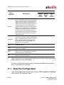
View the Configuration ..................................................................................70
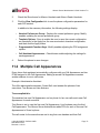
Multiple Call Appearances .............................................................................71
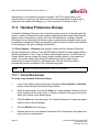
Handset Preference Groups ..........................................................................72
Create New Groups .................................................................................72
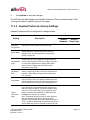
Handset Preference Group Settings ........................................................73
Add Preference Group Options to Templates ..........................................79
Assign Handsets to Handset Preference Groups ....................................80
Delete Handset Preference Groups .........................................................82
Programmable Function Keys (PFKs) ...........................................................82
Enhanced PFK Administration .......................................................................86
Moving Up and Moving Down ..................................................................87
PFK Insertion and Deletion ......................................................................87
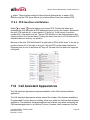
Call Assistant Appearances ...........................................................................87
Handset Templates .......................................................................................88
Default Handset Templates ......................................................................89
View a Handset Template Configuration ..................................................89
Create a New Handset Template .............................................................89
Apply a Handset Template .......................................................................90
Delete a Handset Template .....................................................................91
Modify a Handset Template .....................................................................91
Phone Web Administration ...........................................................................92
Shared Call Appearance .................................................................... 93
Configure Shared Call Appearances .............................................................94
Shared Call Appearance Programmable Function Keys (PFKs) ...................95
Call Routes ....................................................................................................96
Phone LED Indicators ....................................................................................96
Outbound Call ................................................................................................97
Inbound Calls .................................................................................................97
Ringing Call Pickup .......................................................................................97
1-866-ALLWORX * 585-421-3850
www.allworx.com
Revised: 11/22/13
Page v
Allworx Server Administrator’s Guide Version 7.6
Do Not Disturb (DND) ................................................................................... 97
Silence .......................................................................................................... 97
Ignore ............................................................................................................ 98
Active Calls ................................................................................................... 98
Shared Hold .................................................................................................. 98
Privacy Hold .................................................................................................. 98
Bridged Hold ................................................................................................. 99
Park ............................................................................................................... 99
Display PFK Configuration Details ................................................................ 99
Outside Lines ....................................................................................101
Configure the CO Lines ............................................................................... 101
Fax Server Support ..................................................................................... 102
SIP Proxies and SIP Gateways ................................................................... 103
Configure SIP Proxies and SIP Gateways ............................................. 104
SIP Proxy and SIP Gateway Setting Details ........................................ 104
Enterprise Dialing Feature .................................................................... 109
Allworx Enterprise Client ........................................................................ 109
Central Hub / Enterprise Server ............................................................. 109
Limitations with SIP Outside Lines ........................................................ 111
Digital Lines ................................................................................................. 111
Allworx 24x ............................................................................................ 111
Allworx 48x ............................................................................................ 111
PRI Support ........................................................................................... 112
NFAS Support ........................................................................................ 112
Robbed Bit Signaling (RBS) or Channel Associated Signaling (CAS)
Support ............................................................................................. 112
Data Support .......................................................................................... 113
Restrictions ............................................................................................ 114
Configure Digital Lines ........................................................................... 114
Allworx Port Expanders ......................................................................... 119
Port Expander Options .......................................................................... 120
Configure FXO and FXS Ports .............................................................. 121
Outside Line Call Routes ............................................................................ 121
Handle Anonymous Calls ............................................................................ 122
Page vi
1-866-ALLWORX * 585-421-3850
www.allworx.com
Revised: 11/22/13
Allworx Server Administrator’s Guide Version 7.6
Dial Plan ........................................................................................... 123
Dialing Rules ...............................................................................................123
Emergency Dialing .................................................................................124
Home Area Code Requirements ...........................................................124
Service Groups ............................................................................................124
Exceptions ..............................................................................................125
North American Numbering Plan Administration (NANPA) ....................125
Define Service Groups ................................................................................126
External Dialing Rules .................................................................................127
Remote Sites as Services ...........................................................................128
Audit PIN Codes ..........................................................................................129
Dialing Privileges Groups ............................................................................130
Toll Restrictions ...........................................................................................131
Managing Handsets in Dialing Privileges Groups ..................................131
Deleting Dialing Privileges Groups .........................................................132
Service Groups and Handset Outside Line Interaction Restrictions ............132
Unified Messaging ........................................................................... 133
Access Voicemail and Email Messages ......................................................133
Common Mistakes in Forwarding Messages ...............................................134
External SMTP Accounts .......................................................................134
POP3 Client ...........................................................................................135
IMAP Client ............................................................................................135
Back Up and Restore Data .............................................................. 139
Configure Allworx Server Backups ..............................................................139
Restore Data Using OfficeSafe 7 ................................................................140
Server-to-Server Backup and Restore ........................................................142
Remote Allworx Phones and Port Expanders ............................... 143
Phone or Port Expander behind a Third-Party Firewall ...............................144
Difficulty Connecting Calls ...........................................................................144
Multiple Remote Devices behind the Same Firewall ...................................145
Phones at Different Remote Sites, Each with a Firewall .............................147
1-866-ALLWORX * 585-421-3850
www.allworx.com
Revised: 11/22/13
Page vii
Allworx Server Administrator’s Guide Version 7.6
Remote Phones Cannot Receive Pages ..................................................... 147
Adding Extensions ...........................................................................149
User and System Extensions ...................................................................... 149
Basic Routing ......................................................................................... 149
Multiple Destinations Routing ................................................................ 151
Multiple Connection Attempt Routes ..................................................... 151
On Busy Routes ..................................................................................... 152
Follow-Me-Anywhere Routes ................................................................. 152
Caller ID Based Routes ............................................................................... 153
Hot Desk Routes ......................................................................................... 154
Business Schedule Mode Routes ............................................................... 154
Change a Presence Setting ........................................................................ 155
Change Presence via the Allworx Server Admin Page .......................... 155
Change Presence via My Allworx Manager .......................................... 155
Speed Dial Numbers ................................................................................... 155
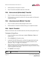
Follow-Me-Anywhere ........................................................................157
Consult ........................................................................................................ 157
Announced (Attended) Transfer .................................................................. 158
Unannounced (Blind) Transfer .................................................................... 158
Quick Transfer ............................................................................................. 158
Voicemail and Escalation Alerts ......................................................159
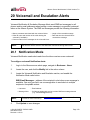
Notification Mode ........................................................................................ 159
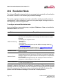
Escalation Mode .......................................................................................... 160
Key System Behavior .......................................................................161
Direct Inward Dialing (DID) ...............................................................163
Emergency Support ..........................................................................165
Emergency Dial Plan ................................................................................... 165
Emergency Handset Caller ID .................................................................... 165
Add Emergency Caller ID Numbers ....................................................... 166
Page viii
1-866-ALLWORX * 585-421-3850
www.allworx.com
Revised: 11/22/13
Allworx Server Administrator’s Guide Version 7.6
Emergency CID displayed on Admin page ............................................167
Delete an Emergency Caller ID ...................................................................168
Emergency Alerts ........................................................................................168
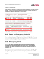
Emergency Call Email Notifications .............................................................169
Call Supervision ............................................................................... 171
Business Schedules ......................................................................... 173
Automatic/Manual Control ...........................................................................173
Assigning Schedules ..............................................................................174
Greetings ................................................................................................175
Create and Modify Schedules .....................................................................176
Call Routing Modes .....................................................................................177
Auto Attendants ................................................................................ 179
Configure the Auto Attendant ......................................................................179
Record Auto Attendant Greetings and Messages .......................................181
Import Auto Attendant Greetings and Messages .........................................183
File Format Conversion ...............................................................................183
Import Greetings and Messages .................................................................185
Assign the Auto Attendant to an Outside Line .............................................186
Call Monitors ..................................................................................... 187
Modify the Call Monitor Description .............................................................187
Set up the Call Monitor in the Call Route ....................................................187
Configure Call Monitor with an Allworx IP Phone ........................................188
Configure Calls to Route to the Call Monitor ...............................................189
Dual Language Support ................................................................... 191
Install the Language Pack ...........................................................................192
Language Settings .......................................................................................193
Outside Lines .........................................................................................193
Other Sites in a Multi-site Network .........................................................194
1-866-ALLWORX * 585-421-3850
www.allworx.com
Revised: 11/22/13
Page ix
Allworx Server Administrator’s Guide Version 7.6
Call Appearances ........................................................................................ 194
Call Applications .......................................................................................... 195
Enable Language Change ..................................................................... 195
Language Change Prompt ..................................................................... 196
User Default Language ............................................................................... 196
Custom Messages ...................................................................................... 196
Parking Orbits ...................................................................................199
Configure Call Parking Orbits ...................................................................... 199
Configure Allworx IP Phone Parking Orbits ................................................ 200
Zoned Paging and Overhead Paging ..............................................201
Paging Amplifier and Door Release Relay .................................................. 201
Paging Zone Settings .................................................................................. 202
Paging Zone Names .............................................................................. 202
Pre-page Tone ....................................................................................... 202
Multi-site Paging .................................................................................... 202
Paging Zone Operation on Handsets .................................................... 203
Allworx Interact Professional Licensing .........................................205
System Settings Import/Export .......................................................207
Export .......................................................................................................... 207
Import .......................................................................................................... 208
Important Notes ........................................................................................... 209
Music on Hold ...................................................................................211
Sources ....................................................................................................... 211
Electronic Files ............................................................................................ 211
Converting Sound Files ............................................................................... 212
Managing Music on Hold ............................................................................. 212
Abbreviations ....................................................................................213
Page x
1-866-ALLWORX * 585-421-3850
www.allworx.com
Revised: 11/22/13
Allworx Server Administrator’s Guide Version 7.6
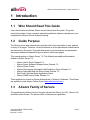
1 Introduction
1.1
Who Should Read This Guide
Users that install and maintain Allworx servers should read this guide. This guide
expects the reader to have computer networking and basic telephony background, and
completed the Allworx Partner technical training.
1.2
Guide Purpose
The Allworx server web administration interface has built-in descriptions, help, and tips
on many of its pages. Therefore, not all the features or all the parameters of each feature
are discussed in this guide. This guide discusses only those features and parameters
that require additional explanation beyond what is on the web pages.
This manual applies to Allworx Server 7.6. The following are additional documents
related to Allworx Server 7.6:
•
•
•
•
•
•
•
Allworx User’s Guide, Release 7.6
Allworx Server Software Release Notes, Release 7.6
Allworx Phone Guides
Allworx Queuing and Automated Call Distribution Guide, Release 7.6
Allworx Advanced Multi-site Setup Guide, Release 7.6
Multi-Tech FaxFinder Setup Application Notes
Allworx SNMP User’s Guide, Release 7.6
These publications as well as System Administrator’s Guides for Releases 7.5 and lower
are available on the Allworx Partner Portal (www.allworxportal.com).
1.3
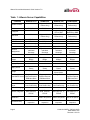
Allworx Family of Servers
The award-winning Allworx family of servers includes the Allworx 6x, 6x12, Allworx 24x,
and Allworx 48x servers. The servers differ in features and capabilities.
1-866-ALLWORX * 585-421-3850
www.allworx.com
Revised: 11/22/13
Page 1
Allworx Server Administrator’s Guide Version 7.6
Table 1: Allworx Server Capabilities
Features
Allworx 6x12
Allworx 6x
Allworx 24x
Allworx 48x
12
30 (up to 60 with
Feature Key)
24 (up to 250 with
Feature Key)
48 (up to 250 with
Feature Key)
6 FXO Ports
6 FXO Ports
3 FXO Ports
3 FXO Ports
N/A
N/A
Integrated single
PRI or RBS
Integrated NFAS,
Dual PRI or RBS
24
60 (up to 120 with
Feature Key)
48 (up to 500 with
Feature Key)
96 (up to 500 with
Feature Key)
2 FXS Ports
2 FXS Ports
5 FXS Ports
5 FXS Ports
SIP 2.0
SIP 2.0
SIP 2.0
SIP 2.0
Multi-site
Branch site only
100 Sites
100 Sites
100 Sites
Voicemail
8-port Voicemail
8-port Voicemail
16-port Voicemail
16-port Voicemail
Presence
Management
7 per User with
Individual
Greetings
7 per User with
Individual
Greetings
7 per User with
Individual
Greetings
7 per User with
Individual
Greetings
9
9
9
9
Conference
Bridges
One (1) 8-seat
Bridge
One (1) 8-seat
Bridge
Four (4) 8-seat
Bridges
Four (4) 30-seat
Bridges
Door Relay
Included
Included
Included
Included
Paging Output
Included
Included
Included
Included
Paging Zones
10 Customizable
Zones
10 Customizable
Zones
10 Customizable
Zones
10 Customizable
Zones
Compact Flash
Compact Flash
Hard Disk with
Mirror Option
Solid State Drive
Supported with
Optional External
USB Hard Drive
Supported with
Optional External
USB Hard Drive
Supported
Email SMTP Server
Supported with
Optional External
USB Hard Drive
Email POP3 Server
Included
Included
Included
Included
Enabled by Mobile
Link Feature Key
Enabled by Mobile
Link Feature Key
Enabled by Mobile
Link Feature Key
Enabled by Mobile
Link Feature Key
Unified Messaging
Included
Included
Included
Included
Network Integration
LAN: Ethernet
WAN: Ethernet,
PPPoE
LAN: Ethernet
WAN: Ethernet,
PPPoE
Number of users
CO Lines
T1 Support
Extensions
Analog phones
VoIP
Auto Attendants
Storage
Email IMAP4
Server
Automatic Call
Distribution
Firewall Security
Page 2
N/A
Stateful Packet
Inspection
LAN: Ethernet
LAN: Ethernet
WAN: Ethernet, T1, WAN: Ethernet, T1,
PPPoE
PPPoE
10 queues; 16 total 10 queues; 32 total 10 queues; 64 total
calls in all queues calls in all queues calls in all queues
Stateful Packet
Inspection
Stateful Packet
Inspection
Stateful Packet
Inspection
1-866-ALLWORX * 585-421-3850
www.allworx.com
Revised: 11/22/13
Allworx Server Administrator’s Guide Version 7.6
Table 1: Allworx Server Capabilities
Features
Allworx 6x12
Allworx 6x
Allworx 24x
Allworx 48x
Call Assistant
Available
Available
Available
Available
Mobile Link
Available
Available
Available
Available
VPN
Audio Prompt
Languages
One user Included
One user Inc.
One user Inc.
One user Inc.
Multi-user Available Multi-user Available Multi-user Available
English; Castilian
English; Castilian
English; Castilian
English; Castilian
Spanish, French
Spanish, French
Spanish, French
Spanish, French
Canadian available Canadian available Canadian available Canadian available
1-866-ALLWORX * 585-421-3850
www.allworx.com
Revised: 11/22/13
Page 3
Allworx Server Administrator’s Guide Version 7.6
Page 4
1-866-ALLWORX * 585-421-3850
www.allworx.com
Revised: 11/22/13
Allworx Server Administrator’s Guide Version 7.6
2 Accessing Web Administration
Supported web browsers for Allworx server administration web pages include:
•
•
•
IE 8, 9, 10 and later
Google Chrome (Latest Release)
Mozilla Firefox (Latest Release)
For upgrades to the software on the server, navigate to the Maintenance > Update web
administration page.
Use a web browser via the LAN interface on TCP port 8088 to access the administrative
interface of the Allworx server.
To connect to the Allworx server admin page when the network settings are set to
factory default:
1.
Plug the PC into the server LAN port.
2.
Set up the network interface on the PC to obtain an IP address automatically
(using DHCP).
3.
Verify the PC has an IP address on the 192.168.2.x network. It may be necessary
to release and renew the IP address on the PC to get an address from the server.
a. Click Start and type cmd in the Search field. A command window opens.
b. Type ip config/release at the prompt and press enter. This clears the
current IP settings from the PC.
c. Type ip config/renew at the prompt and press enter. This obtains a new
IP address for the PC.
4.
Open the browser and enter the URL http://192.168.2.254:8080. When the
Welcome to Allworx page displays, log in using admin as the default username
and password.
When the Allworx server mode is set to NAT/Firewall, NAT/Firewall with DMZ or NAT/
Firewall with Stealth DMZ, the Allworx Server Administrator can also access the
administrative interface via the WAN interface on TCP port 8080. To enable this feature.
click the checkbox labeled admin configuration on WAN interface on the Network
1-866-ALLWORX * 585-421-3850
www.allworx.com
Revised: 11/22/13
Page 5
Allworx Server Administrator’s Guide Version 7.6
Configuration page. After enabling this feature and rebooting the Allworx server, open
the browser and enter the URL of http://<Server WAN IP Address>:8080.
Note:
The WAN administrative option is not available with T1 or PPPoE WAN configurations.
Note:
Prior to accessing the server via the WAN, see “General Network Configuration
Requirements” on page 25, for security requirements.
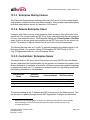
2.1
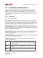
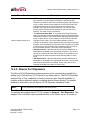
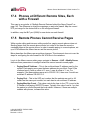
Home Screen
About: Opens the
About window which
provides information
specific to the Server.
Indicates where the
user is within the
application.
Logged in user. Drop-down menu
provides short cuts to Logout,
Change Password, or Change PIN.
Side
Navigation:
Opens the
options
navigation
window specific
to the link topic.
Links to specific topic
windows.
Page 6
1-866-ALLWORX * 585-421-3850
www.allworx.com
Revised: 11/22/13
Allworx Server Administrator’s Guide Version 7.6
2.2
User Roles and Permissions
The Allworx Server Administrator can assign User Permission Levels to users to
delegate some of the administrative task management. See “Role Permissions” on
page 8 to see the administrative tasks and delegation permissions.The users can
access the management task administrative web pages using their Allworx username
and password.
2.2.1
User Roles
The available user roles include:
Server Administrator: predefined system administrator with access to manage all
functions of the server. The Allworx Server Administrator assigns roles, manages the
server administrative functions, manages day-to-day phone system settings, manages
the network and VoIP settings, and initiates system backups and/or reboots.
System Administrator: access to manage the administrative functions of the server.
The user permission setting does not enable this role to change the password of the
Allworx Server Administrator. However, the Allworx Server Administrator can change the
password of the System Administrator.
Phone Administrator: access to manage day-to-day phone system settings including
changes to system recordings as well as adding, changing, and deleting users,
extensions, and handsets.
Network Administrator: access to manage the Network and VoIP settings, as well as
SIP proxies and SIP gateways outside lines.
Support Technician: access to initiate system backups and reboots as well as
managing logging operations.
Note:
Note:
Note:
To enable one user to have roles on different servers in a multi-site network, the
Allworx Server Administrator must create separate user accounts for the user on
each server, and then assign the roles on each server. Use different usernames
for each user account.
The Allworx Server Administrator can assign users to manage queue and auto
attendant recordings. See “User Template Settings” on page 51 for more
information.
The Allworx Server Administrator can assign users to manage individual queue
settings or queue supervisor. See “User Template Settings” on page 51 for more
information.
1-866-ALLWORX * 585-421-3850
www.allworx.com
Revised: 11/22/13
Page 7
Allworx Server Administrator’s Guide Version 7.6
To assign or remove user roles:
1.
Log in to the Allworx server admin page, and navigate to Business > Roles. The
Roles page displays.
2.
Locate the role. The Allworx Server admin page displays a list of users assigned
to each role.
3.
Click the show unassigned users. A list of available users to assign displays on
the page.
4.
Locate the user or users in the list, and click:
•
Assign Role - to assign the role to the user. The designated users have
access to the administration functions that are included in the roles.
•
Remove Role - to remove the user from the assigned role.
When changing a user’s role and the user is logged into the server, the user must
log out and re-login in order to access the changes.
2.2.2
Role Permissions
Each assigned user role has access to specific management tasks. Use the table to
identify the administrative management access level of each User Role.
Allworx Server Page
Link
Phone
Network Support
Home
About
Yes
Yes
Yes
Home
Emergency number dialing
rules “Set”
Yes
No
No
Home
Phone System
Yes
Yes
Yes
Home
Business
Yes
Yes
Yes
Home
Network
Yes
Yes
Yes
Home
Servers
Yes
Yes
Yes
Home
Reports
Yes
Yes
Yes
Home
Maintenance
Yes
Yes
Yes
Home
Need help?
No
No
No
Home
Install Checklist
No
No
No
Home
Logout
Yes
Yes
Yes
Phone System
Audit PIN Codes
Yes
No
No
Page 8
1-866-ALLWORX * 585-421-3850
www.allworx.com
Revised: 11/22/13
Allworx Server Administrator’s Guide Version 7.6
Allworx Server Page
Link
Phone
Network Support
Phone System > Audit PIN Codes
Audit PIN Codes - add new
PIN Code
Yes
No
No
Phone System > Audit PIN Codes
Audit PIN Codes - Dialing
Rules > Modify
No
No
No
Phone System > Audit PIN Codes
Audit PIN Codes - modify
Yes
No
No
Phone System > Audit PIN Codes
Audit PIN Codes Configuration
- modify
Yes
No
No
Phone System > Audit PIN Codes
Audit PIN Codes - Delete
Yes
No
No
Phone System
Auto Attendants
Yes
No
No
Phone System > Auto Attendants
“Manage” the custom
recordings link
Yes
No
No
“View” and manage the
language settings for the Auto
Attendants
No
No
No
Phone System > Auto Attendants
Phone System > Auto Attendants
Auto Attendant n “Modify”
Yes
No
No
Phone System
Modify
Yes
No
No
Phone System > Call Monitors
Call Monitors “Modify”
Yes
No
No
Phone System
Call Park
Yes
No
No
Phone System > Call Park
Call Park “Modify”
Yes
No
No
Phone System > Call Park
Multi-Site Parking “Modify”
Yes
No
No
Phone System
Call Queues
Yes
No
No
Phone System > Call Queues
“manage” the custom
recordings link
Yes
No
No
“View” and manage the
language settings for the Auto
Attendants
No
No
No
Phone System > Call Queues
Phone System > Call Queues
Call Queue n “Modify”
Yes
No
No
Phone System > Call Queues
Queue Streaming Settings
“Modify”
Yes
No
No
Phone System > Call Queues
Queue Busy Reasons modify
Yes
No
No
Phone System
Conference Center
Yes
No
No
Phone System > Conference
Center
Conference X “modify”
Yes
No
No
Phone System
Dial Plan
Yes
No
No
Phone System > Dial Plan
[Reboot phones]
Yes
No
No
Phone System > Dial Plan
Internal Extension Length
“modify”
Yes
No
No
Phone System > Dial Plan
Internal Dial Plan “modify”
Yes
No
No
1-866-ALLWORX * 585-421-3850
www.allworx.com
Revised: 11/22/13
Page 9
Allworx Server Administrator’s Guide Version 7.6
Allworx Server Page
Link
Phone
Phone System > Dial Plan
Internal Dial Plan “view” phone
functions reference card
Yes
No
No
Phone System > Dial Plan
External Dialing Rules “Modify”
NANPA
Yes
No
No
Phone System > Dial Plan
External Dialing Rules “Modify”
Area Code / Exchange
Yes
No
No
Phone System > Dial Plan
External Dialing Rules “Modify”
Emergency
Yes
No
No
External Dialing Rules “Modify”
Emergency Call Email
Notification
Yes
No
No
Phone System > Dial Plan
Phone System > Dial Plan
External Dialing Rules “Modify”
Type / Service Group
No
No
No
Phone System > Dial Plan
Dialing Privileges Groups
“view”
Yes
No
No
Phone System > Dial Plan
Dialing Privileges Groups
“copy”
Yes
No
No
Phone System > Dial Plan
Dialing Privileges Groups
“modify”
Yes
No
No
Phone System > Dial Plan
Dialing Privileges Groups
“delete”
Yes
No
No
Phone System > Dial Plan
Service Groups “add new
Service Group”
Yes
No
No
Phone System > Dial Plan
Service Groups “modify”
Yes
No
No
Phone System > Dial Plan
Service Groups “copy”
Yes
No
No
Phone System > Dial Plan
Service Groups “delete”
Yes
No
No
Phone System
Emergency CID
Yes
No
No
Phone System > Emergency CID
Emergency Caller ID number
“add new caller ID number”
Yes
No
No
Phone System > Emergency CID
Emergency Caller ID number
“modify”
Yes
No
No
Phone System > Emergency CID
Emergency Caller ID number
“delete”
Yes
No
No
Phone System > Emergency CID
Emergency Caller ID numbers
“Modify”
Yes
No
No
Phone System
Extensions
Yes
No
No
Phone System > Extensions
Extensions “add new
extension”
Yes
No
No
Phone System > Extensions
Extensions “view call routes”
Yes
No
No
Phone System > Extensions
Extensions “delete”
Yes
No
No
Page 10
Network Support
1-866-ALLWORX * 585-421-3850
www.allworx.com
Revised: 11/22/13
Allworx Server Administrator’s Guide Version 7.6
Allworx Server Page
Link
Phone
Network Support
Phone System > Extensions
Extensions “username”
Yes
No
No
Phone System > Extensions
Extensions - Bulk Edit
Yes
No
No
Phone System
Handsets
Yes
No
No
Phone System > Handsets
Analog Handsets “new analog
handset”
Yes
No
No
Phone System > Handsets
Analog Handsets “modify”
Yes
No
No
Phone System > Handsets
Analog Handsets “delete”
Yes
No
No
Phone System > Handsets
Analog Handsets “ring”
Yes
No
No
Phone System > Handsets
SIP Handsets [Reboot Allworx
Handsets]
Yes
No
No
Phone System > Handsets
SIP Handsets “add new
Allworx Handset”
Yes
No
No
Phone System > Handsets
SIP Handsets “add new
Allworx Reach Handset”
Yes
No
No
Phone System > Handsets
SIP Handsets “add new
Generic SIP Handset”
Yes
No
No
Phone System > Handsets
SIP Handsets - Bulk Edit
Yes
No
No
Phone System > Handsets
SIP Handsets “handset
preference group”
Yes
No
No
Phone System > Handsets
SIP Handsets “View”
configuration
Yes
No
No
Phone System > Handsets
SIP Handsets “Add” call
appearance
Yes
No
No
Phone System > Handsets
SIP Handsets “Reboot”
Yes
No
No
Phone System > Handsets
SIP Handsets “Replace”
Yes
No
No
Phone System > Handsets
SIP Handsets “Modify”
Yes
No
No
Phone System > Handsets
SIP Handsets “Delete”
Yes
No
No
Phone System > Handsets
SIP Handsets “Ring”
Yes
No
No
Phone System > Handsets
Handset Preference Groups
“View”
Yes
No
No
Phone System > Handsets
Handset Preference Groups
“Copy”
Yes
No
No
Phone System > Handsets
Handset Network Profile
Templates “View”
Yes
No
No
Phone System > Handsets
Handset Network Profile
Templates “Copy”
Yes
No
No
Phone System > Handsets
Handset Configuration
Templates “View”
Yes
No
No
1-866-ALLWORX * 585-421-3850
www.allworx.com
Revised: 11/22/13
Page 11
Allworx Server Administrator’s Guide Version 7.6
Allworx Server Page
Link
Phone
Network Support
Phone System > Handsets
Handset Configuration
Templates “Activate”
Yes
No
No
Phone System > Handsets
Handset Configuration
Templates “Delete”
Yes
No
No
Phone System
Languages
Yes
No
No
Phone System > Languages
“Export” Primary/Secondary
Language Recordings
Yes
No
No
Phone System > Languages
“Import” Primary/Secondary
Language Recordings
Yes
No
No
Phone System > Languages
Language Pack Installation
and Removal
No
No
No
Phone System > Languages
Server Language
Configuration
No
No
No
Phone System > Languages
Call Application Language
Settings
No
No
No
Phone System
Music on Hold
Yes
No
No
Phone System > Music on Hold
Music on Hold “manage”
Yes
No
No
Phone System > Music on Hold
File Statistics
Yes
No
No
Phone System > Music on Hold
Music on Hold Sources
“Usage”
Yes
No
No
Phone System
Outside Lines
Yes
Yes
No
Phone System > Outside Lines
Anonymous Call Handling
“modify”
Yes
No
No
Phone System > Outside Lines
Analog CO Lines
Yes
No
No
Phone System > Outside Lines
Analog CO Lines “new FXO
line”
Yes
No
No
Phone System > Outside Lines
Analog CO Lines “modify”
Yes
No
No
Phone System > Outside Lines
Analog CO Lines “delete”
Yes
No
No
Phone System > Outside Lines
Digital Lines “modify”
Yes
No
No
Phone System > Outside Lines
Direct Inward Dial Blocks “add
new DID block”
Yes
No
No
Phone System > Outside Lines
Direct Inward Dial Blocks
“modify”
Yes
No
No
Phone System > Outside Lines
Direct Inward Dial Blocks
“delete”
Yes
No
No
Phone System > Outside Lines
Direct Inward Dial Routing
Plans “Details”
Yes
No
No
Phone System > Outside Lines
Direct Inward Dial Routing
Plans “Delete”
Yes
No
No
Page 12
1-866-ALLWORX * 585-421-3850
www.allworx.com
Revised: 11/22/13
Allworx Server Administrator’s Guide Version 7.6
Allworx Server Page
Link
Phone
Network Support
Phone System > Outside Lines
SIP Gateways “add new SIP
Gateway”
No
Yes
No
Phone System > Outside Lines
SIP Gateways “modify”
No
Yes
No
Phone System > Outside Lines
SIP Gateways “delete”
No
Yes
No
Phone System > Outside Lines
SIP Proxies “add new SIP
Proxy”
No
Yes
No
Phone System > Outside Lines
SIP Proxies “modify”
No
Yes
No
Phone System > Outside Lines
SIP Proxies “delete”
No
Yes
No
Phone System
Paging
Yes
No
No
Phone System > Paging
Paging Amplifier “modify”
Yes
No
No
Phone System > Paging
Paging Zone Names “modify”
Yes
No
No
Phone System > Paging
Paging Zones “modify”
Yes
No
No
Phone System
Shared Appearance
Yes
No
No
Phone System > Shared
Appearance
Shared Appearance “add new
shared call appearance”
Yes
No
No
Phone System > Shared
Appearance
Shared Appearance “modify”
Yes
No
No
Phone System > Shared
Appearance
Shared Appearance “show
handsets”
Yes
No
No
Phone System > Shared
Appearance
Shared Appearance “delete”
Yes
No
No
Phone System
Speed Dial
Yes
No
No
Phone System > Speed Dial
Speed Dial Numbers “add new
speed dial number”
Yes
No
No
Phone System > Speed Dial
Speed Dial Numbers “modify”
Yes
No
No
Phone System > Speed Dial
Speed Dial Numbers “delete”
Yes
No
No
Business
Contact Information
Yes
No
No
Business > Contact Information
Contact Information “modify”
Yes
No
No
Business
Message Aliases
Yes
No
No
Business > Message Aliases
Message Aliases “add new
alias”
Yes
No
No
Business > Message Aliases
Message Aliases “modify”
Yes
No
No
Business > Message Aliases
Message Aliases “delete”
Yes
No
No
Business
Roles
Yes
No
No
Business > Roles
System Administrator
No
No
No
Business > Roles
Network Administrator
No
No
No
Business > Roles
Phone Administrator
Yes
No
No
Business > Roles
Phone Technician
No
No
No
1-866-ALLWORX * 585-421-3850
www.allworx.com
Revised: 11/22/13
Page 13
Allworx Server Administrator’s Guide Version 7.6
Allworx Server Page
Link
Business > Roles > System
Administrator
[Assign Role] [Remove Role]
Business > Roles > Network
Administrator
[Assign Role] [Remove Role]
Business > Roles > Phone
Administrator
[Assign Role] [Remove Role]
Business > Roles > Phone
Technician
[Assign Role] [Remove Role]
Business
Phone
Network Support
No
No
No
No
No
No
Yes
No
No
No
No
No
Schedules
Yes
No
No
Business > Schedules
Greetings “modify”
Yes
No
No
Business > Schedules
Schedule n [Copy]
Yes
No
No
Business > Schedules
Schedule n [Delete]
Yes
No
No
Business > Schedules
Schedule n “modify”
Yes
No
No
Business > Schedules
Schedule n “add holiday”
Yes
No
No
Business > Schedules
Schedule n “copy holiday”
Yes
No
No
Business > Schedules
Schedule n “delete” holiday
Yes
No
No
Business > Schedules
Schedule n “modify” holiday
Yes
No
No
Business
Users
Yes
No
No
Business > Users
Users “add new user”
Yes
No
No
Business > Users
Users “modify”
Yes
No
No
Business > Users
Users “delete”
Yes
No
No
Business > Users
Users “delete messages”
Yes
No
No
Business > Users
Users “delete recordings”
Yes
No
No
Business > Users
Users “EXTENSION”
Yes
No
No
Business > Users
Users - BULK EDIT
Yes
No
No
Business > Users
Users “show”/”hide” templates
last applied to user
Yes
No
No
Business > Users
User Templates “View”
Yes
No
No
Business > Users
User Templates “Copy”
Yes
No
No
Business > Users
User Templates “Delete”
Yes
No
No
Business > Users
Password Requirements
“modify”
No
No
No
Network
Configuration
No
Yes
No
Network > Configuration
Configuration “modify”
No
Yes
No
Network
Digital Lines
No
Yes
No
Network > Digital Lines
NFAS Lines “modify”
No
Yes
No
Network > Digital Lines
Digital Line n “modify”
No
Yes
No
Page 14
1-866-ALLWORX * 585-421-3850
www.allworx.com
Revised: 11/22/13
Allworx Server Administrator’s Guide Version 7.6
Allworx Server Page
Link
Phone
Network Support
Network
Multi-Site
No
No
No
Network
Multi-Site
No
No
No
Network
Port Expanders
No
Yes
No
Network > Port Expanders
Port Expanders “add a port
expander”
No
Yes
No
Network > Port Expanders
Port Expanders “delete”
No
Yes
No
Network > Port Expanders
Port Expanders “replace”
No
Yes
No
Network > Port Expanders
Port Expanders “handsets”
No
No
No
Network > Port Expanders
Port Expanders “outside lines”
No
No
No
Network > Port Expanders
Port Expanders “px
description” view
No
Yes
No
Network > Port Expanders > View
Port Expander “Modify”
No
Yes
No
Network > Port Expanders > View
Port Expander “Delete”
No
Yes
No
Network > Port Expanders > View
Port Expander “Replace”
No
Yes
No
Network > Port Expanders > View
Port Expander “Handsets”
No
No
No
Network > Port Expanders > View
Port Expander “Outside Lines”
No
No
No
Network > Port Expanders > View
Port Expander [Reboot}
No
Yes
No
Network
Static Routes
No
Yes
No
Network > Static Routes
Static Routes “modify”
No
Yes
No
Network
VPN
No
Yes
No
Network >VPN
Network VPN “modify”
No
Yes
No
Servers
DHCP
No
Yes
No
Servers > DHCP
DHCP Server “modify”
No
Yes
No
Servers > DHCP
Active Leases
No
Yes
No
Servers > DHCP
Known Hosts
No
Yes
No
Servers
DNS
No
Yes
No
Servers > DNS
DNS Server “flush the cache”
No
Yes
No
Servers > DNS
DNS Server “Modify”
No
Yes
No
Servers
Email
No
Yes
No
Servers > Email
Email Server “manage the
email queue”
No
Yes
No
Servers > Email
Email Server “modify”
No
Yes
No
Servers
VoIP
Yes
Yes
No
Servers > VoIP
Severs VoIP “modify”
Yes
Yes
No
Servers
Web
No
Yes
No
Servers > Web
Servers Web “modify”
No
Yes
No
Reports
Auto Notification
No
No
No
1-866-ALLWORX * 585-421-3850
www.allworx.com
Revised: 11/22/13
Page 15
Allworx Server Administrator’s Guide Version 7.6
Allworx Server Page
Link
Phone
Network Support
Reports
Auto Notification
No
No
No
Reports
Call Details
Yes
No
Yes
Reports > Call Details
Call Detail Settings “modify”
Yes
No
Yes
Reports > Call Details
Completed Call Details Report
“delete”
Yes
No
Yes
Reports > Call Details
Completed Call Details Report
[View Report]
Yes
No
Yes
Reports > Call Details
Completed Call Details Report
[Export TSV Report]
Yes
No
Yes
Reports > Call Details
Completed Call Details Report
[Export XML Report]
Yes
No
Yes
Reports
Configuration
No
No
Yes
Reports > Configuration
Configuration Report
[Generate XML Report]
No
No
Yes
Reports > Configuration
Configuration Report “View”
No
No
Yes
Reports > Digital Lines
Digital Line n [Clear Report]
No
Yes
Yes
Reports > Digital Lines
Digital Line n [Refresh Report]
No
Yes
Yes
Reports
Digital Lines
No
Yes
Yes
Reports
Live Calls
No
No
Yes
Reports
Live Calls [Refresh Now]
No
No
Yes
Reports
Network Statistics
No
Yes
Yes
Reports > Network Statistics
Collection Information [Start /
Stop Collecting]
No
Yes
Yes
Reports > Network Statistics
Statistics “Total”
No
Yes
Yes
Reports > Network Statistics
Statistics “IP Address”
No
Yes
Yes
Reports
System Events
No
No
Yes
Reports > System Events
[Download]
No
No
Yes
Reports > System Events
Event Severity Filtering [Apply
Filter]
No
No
Yes
Reports > System Events
Event Severity Filtering [Reset
Default Filter]
No
No
Yes
Reports
Users
Yes
No
Yes
Reports > Users
“USERNAME”
Yes
No
No
Reports > Users
Delete Messages
Yes
No
No
Maintenance
Backup
Yes
Yes
Yes
Maintenance > Backup
Backup “modify”
No
No
No
Maintenance > Backup
[Backup Now}
Yes
Yes
Yes
Maintenance
Feature Keys
Yes
Yes
Yes
Page 16
1-866-ALLWORX * 585-421-3850
www.allworx.com
Revised: 11/22/13
Allworx Server Administrator’s Guide Version 7.6
Allworx Server Page
Link
Phone
Network Support
Maintenance > Feature Keys
Feature Keys [Install]
Yes
Yes
Yes
Maintenance > Feature Keys
Feature Keys [Submit]
Yes
Yes
Yes
Maintenance > Feature Keys
Feature Keys “Allworx Reach”
Yes
Yes
Yes
Maintenance > Feature Keys
Feature Keys “Generic SIP
Handsets”
Yes
Yes
Yes
Maintenance > Feature Keys
Feature Keys “Allworx Interact
Professional”
Yes
Yes
Yes
Maintenance
Import / Export
Yes
Yes
Yes
Maintenance > Import / Export
Export Configuration [Export]
Yes
Yes
Yes
Maintenance > Import / Export
Import Configuration [Choose
File]
No
No
No
Maintenance > Import / Export
Import Configuration [Load]
No
No
No
Maintenance
Restart
Yes
Yes
Yes
Maintenance > Restart
[Restart Now]
Yes
Yes
Yes
Maintenance > Restart
[Restart Later]
Yes
Yes
Yes
Maintenance > Restart
[x] Restart Server
Yes
Yes
Yes
Maintenance > Restart
[x] Restart Phones
Yes
Yes
Yes
Maintenance
Time
Yes
Yes
Yes
Maintenance > Time
Maintenance Time “modify”
Yes
Yes
Yes
Maintenance
Tools
Yes
Yes
Yes
Maintenance > Tools
Network Diagnostics
Yes
Yes
Yes
Maintenance > Tools
Syslog - System Events
Yes
Yes
Yes
Maintenance > Tools
Allworx Technical Support
Server
Yes
Yes
Yes
Maintenance > Tools
Advanced Troubleshooting
Yes
Yes
Yes
Maintenance > Tools
Network Address Translation
(NAT) Information
Yes
Yes
Yes
Maintenance > Tools
Four Wire Return Loss
Measurements
Yes
Yes
Yes
Maintenance > Tools
Network Statistics Logging
Yes
Yes
Yes
Maintenance > Tools
Packet Capture Tool
Yes
Yes
Yes
Maintenance > Tools
Telnet
Yes
Yes
Yes
Maintenance > Tools Advanced
Troubleshooting
Advanced Diagnostics
Yes
Yes
Yes
Maintenance
Update
No
No
No
1-866-ALLWORX * 585-421-3850
www.allworx.com
Revised: 11/22/13
Page 17
Allworx Server Administrator’s Guide Version 7.6
Page 18
1-866-ALLWORX * 585-421-3850
www.allworx.com
Revised: 11/22/13
Allworx Server Administrator’s Guide Version 7.6
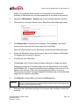
3 Configuring a New Allworx Server
To configure a new Allworx server:
1.
Log in to the Allworx server admin page. The Home page displays.
2.
Click the Install Checklist link (on the left side) to open a new window that lists
the steps necessary to configure a new server. Each step has a description
followed by a link to the appropriate web admin page to execute the step. Follow
the order of the steps aid for a successful configuration. Most of the administrative
pages for each step contain all the descriptions and help necessary to carry out
the step. Use this guide to supplement the information on the web pages, when
necessary.
3.1
Set the Time
Users can opt to set the time on the server using NTP to set the time automatically or
adjust the time and date manually. The preferred setting is NTP, if the server has
Internet access.
To set the time:
1.
Log in to the Allworx server admin page, and navigate to Maintenance > Time.
2.
Click the modify link in the Action column. The Time page displays.
3.
Click the radio button to select an option:
4.
•
Use NTP to set time automatically. In the NTP server field, specify an
SNTP-server IP address or a domain name. In the Poll Period, specify the
number of minutes between polls.
•
Set time manually - specify the time in hours, minutes, seconds, and date in
the respective fields.
Locate the Time Zone section and select the time zone from the drop-down list.
a. Check the Automatically adjust clock for Daylight Saving Time box
underneath the selected time zone to enable the system to update the time
automatically.
1-866-ALLWORX * 585-421-3850
www.allworx.com
Revised: 11/22/13
Page 19
Allworx Server Administrator’s Guide Version 7.6
b. Click the Get Time button to update the clock to the current time when using
an SNTP server to specify the time.
5.
Click the Set Time button to save changes.
3.2
Business Contact Information
The page displays the Business Contact Information (Name, Address, Phone number,
etc.).
Entering the Business Contact Information is optional.
To add or modify the contact information:
1.
Log in to the Allworx server admin page, and navigate to Business > Contact
Information. The Contact Information page displays.
2.
Click the Modify link.
3.
Enter Name, Street, City, State Zip, Phone, FAX, and Home Page information.
Click the Start Over button to clear the fields and re-enter the information.
4.
Click Update to save changes.
3.3
Feature Keys
Feature Keys enable access to advanced server features, and are available as a
separate purchase from the base feature set for Allworx servers. Newly purchased or
existing keys issued for a specific Allworx server automatically download from the Online
Allworx key database.
To install Feature Keys via the Internet:
1.
Log in to the Allworx server admin page, and navigate to Maintenance > Feature
Keys. The Feature Keys page displays.
Page 20
1-866-ALLWORX * 585-421-3850
www.allworx.com
Revised: 11/22/13
Allworx Server Administrator’s Guide Version 7.6
2.
Click Install.
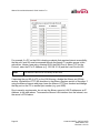
Feature
Key
Description
Expand the maximum number of users on 6x, 24x, and 48x. The expansion does not
require downloading any additional software, unless otherwise specified. The User
Expansion feature is not available for 6x 12 servers.
Key
User
Expansion
License
Call Queuing
6x
48 Users
60 Users
24x
48x
X
X
100 Users
X
X
150 Users
X
X
200 Users
X
X
250 Users
X
X
Provide the ability to direct inbound calls into queues. These calls ring the phones of
available, designated users to service the calls.
Directs calls in a queue to agents using a variety of call distribution algorithms. This key
also enables the method described for the Call Queuing key. If installing the Automatic
Automatic Call Call Distribution feature key, the Call Queuing feature key is not required. The Automatic
Distribution
Call Distribution feature is not available for 6x12 servers.
Note:For details on configuring and using Call Queuing and Automatic Call Distribution,
see the Allworx Queuing and Automated Distribution Guide.
Call Assistant
Enable the Allworx Call Assistant and the TSP driver. The Allworx Call Assistant is a
PC-based answering system, which brings the power of enterprise attendant consoles
directly to small business. Use an Allworx desk phone with this software, requires
additional software.
Note: TSP (Telephony Service Provider) is a separate PC driver that enables dialing
from within contact management software, such as Microsoft Outlook.
Conference
Center
Reserve the conference center, and offers password-restricted access for attendees.
This option does not require any additional software.
Dual
Language
Support
Provide the capability of a second language for default audio prompts. Language Packs
containing audio prompts in languages other than US English are available for download
from the Allworx Partner Portal at www.allworxportal.com.
Extended
Warranty
Extend the expiration of the Allworx server’s warranty by 60 months. Obtain this key
through the Allworx Partner Portal.
Generic SIP
Handsets
Enables newly created Generic SIP handsets on the system. Each Allworx server
enables configuration of either 3 or 5 generic handsets (3 on the 6x12 and 6x; 5 on the
24x/48x) without purchasing a feature key. Generic SIP handsets existing in the system
prior to the 7.5 upgrade operate without the purchase of a feature key package.
1-866-ALLWORX * 585-421-3850
www.allworx.com
Revised: 11/22/13
Page 21
Allworx Server Administrator’s Guide Version 7.6
Feature
Key
Allworx
Interact
Professional
Mobile Link
Description
Enables users to control a handset with convenient access to call history and contacts
from the Allworx directory, and accesses personal directory contacts from the user’s
Microsoft® Outlook® application. The Allworx Interact Professional application enables
users to Answer, Ignore, End, or place calls on Hold. Additionally, users can Transfer,
Park, Conference, and settings features.
Enables interaction between the Allworx system and the iAllworx for iOS or Mobile Link
for Android. Each application enables users to set their Presence, review conferences,
and receive/send voicemails. The Mobile Link key is required to enable the IMAP
protocol for the voicemail to email feature.
Additionally, this key enables voicemail-only functionality with the Allworx Reach
application without an Allworx Reach key or Allworx Reach handset.
Multi-Site
Primary
Provide the ability to integrate multiple sites seamlessly. The Primary key designates the
Controller site for the network. At least one site in the network must have a Multi-site
Primary key. More than one site can have a primary key. It also enables a larger number
of BLF/DSS between sites (up to 255) than the Multi-site Branch key (up to 10). The
Multi-Site Primary feature is not available for 6x12 servers.
Multi-Site
Branch
Provide the ability to integrate seamlessly multiple sites. The Branch key enables sites to
join a network of sites but not configured as the controller site. Sites without a Multi-site
Primary key are limited to DSS/BLF for a maximum of 10 handsets from other sites.
Order Feature key licenses in increments of 1, 5, and 10, and the feature counts are
additive. Installing multiple keys for the same or different feature count adds licenses to
the server. Once the Allworx Reach licenses are active on a server, the Allworx Server
Allworx Reach
Administrator can configure users to claim licenses on a first come, first server basis.
Each Allworx server enables configuration of a single instance of the Allworx Reach
application without the purchase of a feature key.
Software
Upgrade
Enable system software updates. Without this key, only patch updates to the currently
loaded release are available.
Virtual Private Enables access to remote and secure data. This key is not required for opening a singleNetwork
user remote diagnostic VPN. This option does not require any additional software. The
(VPN)
VPN feature is not available for 6x12 servers.
T1/PRI
License #1
(48x only)
Activates the T1-A port on an Allworx 48x system. T1/PRI License #1 (48x only).
T1/PRI
License #2
(48x only)
Activates the T1-B port on an Allworx 48x system. This does not include the license for
the first T1. Install T1 license #1 in order to activate the T1 #2. T1/PRI License #2 (48x
only).
Note: Feature keys activate features only on the Allworx server for which they are generated. Therefore,
another system cannot use feature keys generated a different system cannot.
Page 22
1-866-ALLWORX * 585-421-3850
www.allworx.com
Revised: 11/22/13
Allworx Server Administrator’s Guide Version 7.6
4 Upgrade Server Software
Before doing an upgrade, be aware that:
•
If updating from Release 7.0 or lower, Allworx has made significant changes to
multi-site networking that require additional feature keys and configuration
steps in order for site-to-site features to continue to operate. Multi-site
networks will cease functioning until completing the server updates, procuring
and installing the new keys, and doing additional configurations on each site.
See the Allworx Advanced Multi-site Setup Guide on the Allworx portal. for
more details.
•
Downgrading from one release to an earlier release results in undesirable
behavior and is not supported.
•
Allworx highly recommends running an OfficeSafe backup prior to the upgrade
(See “Back Up and Restore Data” on page 139.).
•
The upgrade requires a server reboot. Since this causes disconnections and
disruption of data, verify the system is idle (no phone or data users) when the
upgrade is done.
•
After installing, close all browser windows and open a new browser window
before proceeding. If there is a browser session open during the upgrade, the
Allworx server admin page may not display properly.
•
See page 5 for supported web browsers.
Note:
Note:
Upgrading from prior releases of the Allworx System Software to Release 7.6
requires installing a Software Upgrade Feature Key or that the server is in its
initial software warranty period (90 days).
Do not skip software releases to install Allworx System Software Release 7.6. If
upgrading from Release 7.3 or lower, upgrade to the next release in sequence
until the server is running Release 7.4. Then install Release 7.5, and finally
install Release 7.6.
To upgrade the server:
1.
Log in to the Allworx server admin page, and navigate to Maintenance > Update
page.
1-866-ALLWORX * 585-421-3850
www.allworx.com
Revised: 11/22/13
Page 23
Allworx Server Administrator’s Guide Version 7.6
2.
Click an update option.
•
Download update from web: the server determines if new software releases
are available. If an upgrade is available, the option to install them is available.
Select the software version, and then click Download Update.
•
Upload update from PC:
a. Download the update file to a PC from the Allworx portal
(www.allworxportal.com).
b. Click the Browse button to navigate to the location of the downloaded Allworx
server software file from the Allworx portal.
c. Select the file, and click Open. The Update page displays.
d. Click the Load button. The page displays the current version of software and
the software version of the file that was loaded on the system. A warning
message displays for any inconstancies such as:
3.
•
Update version is the same or lower than the current version.
•
Update is for a different Allworx server model.
Select an option to activate the server software update.
Note:
After installing, close all browser windows and open a new browser window before
proceeding. If there is a browser session open during the upgrade, the Admin page may
not display properly.
Option
Description
Activate Update Now
Update begins immediately.
1. Click Activate Update Now.
2. (optional) Check the Automatic Update box to update Allworx
Phone firmware automatically.
3. Click the Start Update button.
Active Update Later
Schedule the update to begin at another time - up to one week later.
1. Click Activate Update Later.
2. (optional) Check the Automatic Update box to update Allworx
Phone firmware automatically.
3. Select the date and time to begin the update, and then click the
Submit Schedule button. The Update page displays with the
scheduled date and time for the server software update.
Cancel Update
Ends the update and returns to the main update screen.
Page 24
1-866-ALLWORX * 585-421-3850
www.allworx.com
Revised: 11/22/13
Allworx Server Administrator’s Guide Version 7.6
5 Configuring the Network
5.1
General Network Configuration
Requirements
If connecting remote phones or remote Px Expanders to the system, observe the
following very important security requirements:
•
The Allworx Server Administrator can directly connect the Allworx server to the
Internet via its WAN port. However, the WAN cannot be in Use PPPoE mode.
•
Install the server behind a firewall or connect it to the public Internet using the
WAN port. DO NOT connect the Allworx LAN port directly onto the public
Internet.
•
Disable Allworx WAN services (ports) not in use.
•
Change voicemail ports (SMTP and IMAP) to non-standard port numbers.
•
Change all server admin, phone admin, and user passwords from the default
values.
•
Use strong passwords for server and phone administration pages. DO NOT use
simple passwords such as “1234” or “Allworx”.
•
Verify that there is no exposure of the Admin Page (Port 8080) to the Public
network. DO NOT port forward directly to the LAN port of an Allworx server from
the customer’s router. For remote maintenance, use the Allworx VPN. Navigate
to Home > Network > VPN > modify to configure the VPN settings.
When configuring the WAN interface to connect to the public Internet:
Enable the server in NAT Firewall mode, preferably with Stealth DMZ. In stealth mode,
the WAN interface does not respond to “pings” from other devices.
Note:
Allworx cannot guarantee proper operation of third-party networking products. However,
Allworx expects this to work with typical firewalls and tests against several brands. Some
NAT/Firewall configuration may be required. See “Allworx Server behind a Third-Party
NAT Firewall” on page 31 for more information.
The Allworx server provides powerful and flexible network infrastructure capability by
setting the Network Mode parameter on the Network > Configuration page. This page
1-866-ALLWORX * 585-421-3850
www.allworx.com
Revised: 11/22/13
Page 25
Allworx Server Administrator’s Guide Version 7.6
displays the different parameter sets depending on the Network Mode setting. If the
Network Mode is set to the factory default value of NAT/Firewall with DMZ, the page is
similar to the one shown below.
Page 26
1-866-ALLWORX * 585-421-3850
www.allworx.com
Revised: 11/22/13
Allworx Server Administrator’s Guide Version 7.6
5.2
Network Mode: Standard Router
When the network mode is set to Standard Router, the logical network capability is
shown in the diagram below:
The server acts like an ordinary two port router with the server routing packets between
the LAN and WAN interfaces. No NAT or firewall functionality is enabled. All LAN hosts
are visible on the WAN. If the DHCP server is enabled (the Servers > DHCP Server
page), then the DHCP server sends its LAN IP address as the DHCP router (gateway)
option so that LAN clients know to use the Allworx server as the router to the WAN. WAN
hosts wanting to connect to LAN hosts needs to be configured with a network route
using the Allworx server’s WAN address as a gateway to the LAN.
1-866-ALLWORX * 585-421-3850
www.allworx.com
Revised: 11/22/13
Page 27
Allworx Server Administrator’s Guide Version 7.6
5.3
Network Mode: LAN Host
When the network mode is set to LAN Host, the logical network capability is shown in the
diagram below:
Use this mode to deploy the Allworx server as a peer (instead of as a router or firewall)
on the local area network.
This mode is the same as Standard Router except that when the DHCP server is
enabled, it passes out the configured Gateway address (set on the Network >
Configuration > Modify page) as the DHCP router (gateway) option instead of giving
out the Allworx server’s LAN address.
When in this mode, Allworx recommends not connecting the WAN network port (i.e. not
plugging in the network cable). Even though there is no network connection, assign a
WAN IP address and subnet mask. Use a subnet number that is distinct from the LAN
subnet number when assigning the WAN IP address. Use a completely unused subnet
number to avoid any routing conflicts.
The WAN services (like FTP and HTTP) are still available via the LAN if the proper
routes are configured on the network.
Page 28
1-866-ALLWORX * 585-421-3850
www.allworx.com
Revised: 11/22/13
Allworx Server Administrator’s Guide Version 7.6
5.4
Network Mode: NAT/Firewall
When the network mode is set to NAT/Firewall, the logical network capability is shown in
the diagram below:
For security purposes, the mode default settings enable only outbound connections
(from the LAN to the WAN); all WAN-initiated connections are denied. In addition, all
packets are subject to network address translation (NAT). Because of this, the
addresses of devices on the LAN are not visible on the WAN, but the WAN is accessible
outbound traffic. These features reduce the ability of WAN hosts to attack LAN hosts.
Expose the specific LAN sports to enable WAN access to specific LAN network services
through the firewall. To configure, navigate to Network > Configuration > Modify and
locate the Firewall section.
1-866-ALLWORX * 585-421-3850
www.allworx.com
Revised: 11/22/13
Page 29
Allworx Server Administrator’s Guide Version 7.6
For example, if a PC on the LAN is hosting a website that requires Internet accessibility,
the http port (port 80) must be exposed through the firewall. To enable access to this
web server, create a new entry, entering 80 for the WAN Port #. Select TCP for the
Protocol, enter the PC’s IP Address (e.g. 192.168.101.9) and the Local Port # of 80.
Note:
The WAN and LAN Port #s must always be the same.
If exposing the port 80 of a PC on the LAN this way, disable the Allworx port 80 http
service. Uncheck the HTTP (80) checkbox in the Allworx Services section of the page. If
using the Allworx Internet web page, leave the Allworx HTTP box checked and change
the http port on the PC to another port number (e.g. port 5000).
Due to security requirements, do not use the Allworx server’s LAN IP address as an IP
Address, in the table above. To access the Allworx LAN interface from the Internet, use
the server’s VPN feature.
Page 30
1-866-ALLWORX * 585-421-3850
www.allworx.com
Revised: 11/22/13
Allworx Server Administrator’s Guide Version 7.6
5.5
Allworx Server behind a Third-Party NAT
Firewall
To support remote devices, Allworx Reach Mobile Clients, and SIP Proxy usage when
the Allworx server is behind a single third-party NAT firewall, the server’s Network Mode
must be in LAN Host Mode.
When set to LAN Host Mode, the page contains a Public IP Address section shown
below:
As instructed on the page, enter the firewall public IP address in the Public IP Address
field. In addition, it may be necessary to configure the firewall to statically map specific
ports.
Note:
The box on the web page describes this and is discussed further in the document.
1-866-ALLWORX * 585-421-3850
www.allworx.com
Revised: 11/22/13
Page 31
Allworx Server Administrator’s Guide Version 7.6
5.6
Network Mode: NAT/Firewall with DMZ
When the network mode is set to NAT/Firewall with DMZ, the logical network capability is
shown in the diagram below:
Turning on the DMZ moves the WAN network services behind the firewall. This means
that even the Allworx WAN services (POP, SMTP, FTP, HTTP, etc.) are not available by
hosts on the WAN.
To enable some of these services available, navigate to Network > Configuration >
Modify, and edit the Firewall section of the page.
Page 32
1-866-ALLWORX * 585-421-3850
www.allworx.com
Revised: 11/22/13
Allworx Server Administrator’s Guide Version 7.6
Note:
Use the check boxes for configuring specific Allworx services in the LAN address
list. The system provides these check boxes as a convenience instead of filling
in the list.
1-866-ALLWORX * 585-421-3850
www.allworx.com
Revised: 11/22/13
Page 33
Allworx Server Administrator’s Guide Version 7.6
5.7
Network Mode: NAT/Firewall with Stealth
DMZ
This mode is the same as NAT/Firewall with DMZ except that all ICMP services (echo,
redirect, etc) are off. This makes it more difficult for attacks from the WAN to probe the
server. It also makes it more difficult for the administrator to troubleshoot any network
connectivity problems (since ping and traceroute won’t work).
Example 1: Secure Firewall
Requirements
Use the Allworx server as the router between a
LAN and the Internet. Protecting the LAN from
the Internet is a requirement. Use the server as
the local email server with email being sent to it
from the WAN and LAN. The server is the LAN
timeserver. All other WAN services will be
denied.
Configuration
Set the Network Mode to NAT/Firewall with Stealth
DMZ. Setting it to stealth mode reduces the ability of
Internet attacks to recognize the existence of the
Allworx server and its offered services.
Navigate to Network > Configuration > Modify and
edit in the Firewall section of the page, change the
Allworx Services (ports) exposed through DMZ so that
only SMTP, DNS, and SNTP are checked. Receiving
mail from the Internet requires SMTP for local users.
The email server requires DNS to resolve outbound
mail addresses. The server requires SNTP to get
accurate time from an Internet time server (configured
on the Maintenance > Time page).
Example 2: Secure Firewall with Third-Party Email Server
Requirements
Configuration
The configuration is identical to the previous example
except for the following changes:
Uncheck the SMTP service from the list of exposed
Allworx services.
The requirements are identical to Example 1:
Secure Firewall except that instead of using the Go to Network > Configuration > Modify and edit in
Allworx server as the email server and uses
the Firewall section of the page, add an entry to LAN
another host (at 192.168.101.12) on the LAN as Addresses exposed through firewall where:
the email server.
• WAN Port # is 25.
• Protocol is TCP.
• IP Address is set to the LAN email server,
192.168.101.12
• Local Port # is 25.
Page 34
1-866-ALLWORX * 585-421-3850
www.allworx.com
Revised: 11/22/13
Allworx Server Administrator’s Guide Version 7.6
5.8
FTP File Transfer
By default, FTP is disabled on the Allworx server. The Allworx Server Administrator must
enable this setting to import/export Auto Attendant greetings and recordings. See
“Import Auto Attendant Greetings and Messages” on page 183 for more information.
To enable or disable FTP on the Allworx server:
Note:
The FTP server remains enabled for one hour after enabling it. After one hour or
a server reboot, the FTP server disables access.
1.
Log in to the Allworx server admin page, and navigate to Servers > Web.
2.
Locate the FTP Server section, and click the Enable or Disable button. The
server provides or denies access as requested.
1-866-ALLWORX * 585-421-3850
www.allworx.com
Revised: 11/22/13
Page 35
Allworx Server Administrator’s Guide Version 7.6
Page 36
1-866-ALLWORX * 585-421-3850
www.allworx.com
Revised: 11/22/13
Allworx Server Administrator’s Guide Version 7.6
6 Virtual Private Network (VPN)
Note:
It is necessary to restart the Allworx server for the new Network VPN settings to take
effect.
To enable the VPN PPTP server:
1.
Log in to the Allworx server admin page, and navigate to Network > VPN. The
VPN page displays.
2.
Click the Modify link to update the values.
3.
Check the Enable VPN PPTP Server box and update the fields.
4.
Enter the required information in the respective fields. Click the Start Over button
to reset the fields to the original settings.
5.
Click Update to save changes.
6.
Reboot the Allworx server.
To enable VPN for Individual Users:
1.
Log in to the Allworx server admin page, and navigate to Business > Users. The
Users page displays.
2.
Locate the username in the Users table, and click the Modify link. The Modify
dialog box displays.
3.
Locate the VPN Settings section, and check the VPN Access box.
4.
Enter a VPN password in the field, and then Confirm VPN Password in the next
field.
5.
Click Update to save the changes.
1-866-ALLWORX * 585-421-3850
www.allworx.com
Revised: 11/22/13
Page 37
Allworx Server Administrator’s Guide Version 7.6
Page 38
1-866-ALLWORX * 585-421-3850
www.allworx.com
Revised: 11/22/13
Allworx Server Administrator’s Guide Version 7.6
7 Extension Length / Internal Dial Plan
The Extension Length setting configures extensions to be three-digits or four-digits long.
This capability affects other server features and has some limitations discussed below.
The Internal Dial Plan specifies the first digit for user extensions and other PBX functions
such as forwarding calls and accessing outside lines. The Allworx Server Administrator
can configure the dial plan to meet the needs of the customer by:
•
Matching extensions to DID numbers.
•
Keeping the same extensions prior to the introduction of the Allworx system.
•
Changing the PBX outside line access to a digit other than “9” to avoid
accidental 911 calls.
•
Both Extension Length and the Internal Dial Plan affect many system features.
Allworx recommends configuring the options early in the installation process.
7.1
Extension Length
7.1.1
Set the Extension Length
The factory configuration of an Allworx server is three-digit extensions and does not
require changes. If using four-digit extensions, Allworx recommends changing the
extension length to four digits before defining any Users, Handsets, or Extensions.
To change the extension length on new systems:
1.
Log in to the Allworx server admin page. Navigate to Phone System > Dial Plan.
2.
Locate the Internal Extension Length section, and click the Modify link.
3.
Change the User and System Extensions to four digits in length.
4.
Click Update to save the configuration, and boot any previously configured
handsets.
Note:
Systems part of multi-site networks cannot change the Extension Length.
1-866-ALLWORX * 585-421-3850
www.allworx.com
Revised: 11/22/13
Page 39
Allworx Server Administrator’s Guide Version 7.6
7.1.2
Change the Extension Length on Existing Systems
When switching an existing server with three-digit extensions to four-digit extensions, the
user and system extensions automatically change to four digits. The server adds the
number one to the start of each extension. For example, if a user has the extension
x104, the extension automatically updates to x1104. A system extension of x231
updates to x1231.
Allworx does not recommend switching from four-digit extensions to three-digit
extensions. When switching, the system shortens all extensions to three digits by
removing the first digit (e.g., an extension of x1205 becomes x205). However, this can
lead to conflicts (e.g. x1100 and x2100 would shorten to the same three-digit extension).
Therefore, the system prevents switching from four-digit extensions to three-digit
extensions, if there are any extensions outside the x1100-x1299 range. For sites using a
non-default internal dial plan, verify all extensions are in the x100 – x299 range. For
example, if the site’s extensions are 4xxx – 5xxx, verify all extensions are in the
4100-4299 range to switch to three-digit extensions. If there are extensions outside of
this range and the requirement is to switch from four-digit extensions to three-digit
extensions, change or delete all extensions outside the range.
The following affects phone functions when changing the extension length setting. The
number format to dial is the same but the number of digits changes, depending on
whether extensions are set to three digits or four digits.
Function
Format**
3-digit
Example**
4-digit
Example*
Leave a voicemail
3 + extension
3199
31199
Check voicemail
6 + extension
6199
61199
Call forwarding
45 + extension
45199
451199
Answer alternate extension
7 + extension
7199
71199
** Extensions may vary per system. When using a non-default Internal Dial Plan, consult
the My Allworx Manager Phone Features tab to determine what extensions to use for the
corresponding feature.
In addition to the changes in user and system extensions, the following server
configurations automatically update when changing from three-digit to four-digit
Page 40
1-866-ALLWORX * 585-421-3850
www.allworx.com
Revised: 11/22/13
Allworx Server Administrator’s Guide Version 7.6
extensions:
•
Extension call routes including Internal Caller-ID checking
•
Incoming outside line call routes
•
DID mappings
•
System Speed Dials (the Speed Dial extension doesn’t change but the dialed
extension changes)
•
Speed Dial PFK (differs from Personal Speed Dial PFK)
•
Default Extensions, extensions accessed by Shortcuts, and “Dial By Directory”
listings of Auto Attendants
•
Call Detail Records (prior records are unaffected by the change)
•
Off hook digits dialed for handsets
Extension Length changes do not affect the following server configurations1:
•
Personal Speed Dials (users must modify since the numbers are stored on the
phones)
•
System Speed Dial extensions (350-399, 34000-34999)
•
Call Park extension and Parking Orbits (700-709)
•
Auto-Attendant extensions (400, 431-439)
•
Door Relay (403)
•
Message Center (404)
•
Conference Center (408)
•
Paging extensions (460-469)
•
Queue extensions (4400-4409, 4410-4419)
•
Modifying Internal Dial Plan
1. Extensions may vary per system. When using a non-default Internal Dial Plan, consult the My
Allworx Manager Phone Features tab to determine what extensions to use for the
corresponding feature.
1-866-ALLWORX * 585-421-3850
www.allworx.com
Revised: 11/22/13
Page 41
Allworx Server Administrator’s Guide Version 7.6
7.2
Internal Dial Plan
There are two configuration modes for the Internal Dial Plan:
•
Normal Mode - User and system extensions are a continuous range of 200
three-digit extensions or 2000 four-digit extensions numbers. The numeric range
varies between 1xx and 9xx. Examples: three-digit extensions between 100 and
299 or between 700 and 899. System functions (e.g., Speed Dials and retrieving
parked calls) are in other ranges not assigned to user extensions.
•
Extension Mode - User and system extensions can be in any numeric range.
The server reserves only the operator digit (e.g.,0) and the PBX external dial
digit (e.g., 9). System functions begin with an asterisk (*). For example,
extensions can range between 100 and 899 or 1000 and 8999.
To view the Internal Dial Plan, navigate to Phone System > Dial Plan > Internal Dial
Plan, and click modify to change the dial plan. Normal mode is the default setting. Click
the Use Extension Mode check box to change modes. If the system is part of a
Multi-site network, the Allworx Server Administrator cannot change the Internal Dial Plan
between Normal Mode and Extension Mode.
In either mode, select the leading digit for groups of dialing patterns from a drop-down
list. Selecting a digit for one pattern affects the digits that are available for use with other
patterns. While making the selection, the system automatically adjusts the lists for other
dial patterns to include only valid remaining digits. For this reason, Allworx recommends
making selections starting at the top of the page.
Page 42
1-866-ALLWORX * 585-421-3850
www.allworx.com
Revised: 11/22/13
Allworx Server Administrator’s Guide Version 7.6
To disable Multi-site on all servers:
1.
Login to the Allworx server admin page, navigate to Network > Multi-Site >
modify, and locate the Configuration section.
2.
Click the Disabled button.
3.
Click the Remove links on all servers to remove all site data on all servers.
4.
Navigate to the Phone System > Dial Plan > Internal Dial Plan section, and
click the modify link.
5.
Confirm that the Internal Dial Plan is identical on all servers - Normal or Extension
Mode.
6.
Reboot all phones, and enable Multi-site on the Primary site.
a. Navigate to Network > Multi-Site > modify.
b. Locate the Configuration section, and click the Controller Site button.
7.
Enable Multi-site on all of the Branch sites and Accept all sites into the network on
the Primary site.
a. Navigate to Network > Multi-Site > modify.
b. Locate the Configuration section and click the Branch Site button.
8.
Verify that the multi-site network is operating properly. Run the Multi-site Tests on
the Network > Multi-Site page and place calls between all combinations of
servers.
7.3
Important Notes
Note:
If installing Generic SIP phones on the system, Internal Dial Plan changes can
modify the configuration on the server such that the Generic SIP phones no
longer register.
To examine the configuration:
1.
Login to the Allworx server admin page and navigate to Phone System >
Handsets.
1-866-ALLWORX * 585-421-3850
www.allworx.com
Revised: 11/22/13
Page 43
Allworx Server Administrator’s Guide Version 7.6
2.
Examine the installed Generic SIP phone User IDs.
3.
Determine if the registration configuration for each Generic SIP phone is the
same or different from the current User ID on the server Handsets page. If there is
a difference, modify the on-phone configuration to match the new User ID.
Note:
Note:
7.4
Allworx user guides frequently refer to dialing patterns based on the factory default
Internal Dial Plan. After making changes to the dial plan, the My Allworx Manager Phone
Functions tab automatically updates to the new digits. Print and distribute this sheet to all
end users. Navigate toPhone System > Dial Plan to view the Phone Functions
Reference Card.
Changing the Operator to something other than “0” does not automatically change the
Operator digit shortcut in the Auto Attendants. If changing the Operator digit, manually
update the Auto Attendants shortcuts. To update manually, see “Auto Attendants” on
page 179.
Multi-site Calling
For reliable calling between sites in a multi-site network, all Allworx servers must have
the same software release, extension length, and internal dial plan.
Page 44
1-866-ALLWORX * 585-421-3850
www.allworx.com
Revised: 11/22/13
Allworx Server Administrator’s Guide Version 7.6
8 User Passwords
The system maintains a PIN code for accessing phone functions (accessing the
Message Center, logging in to Queues, etc.) and a password for accessing My Allworx
Manager and the Allworx Administration pages.
Allworx Server Administrators can enforce more stringent password requirements for all
user accounts, and/or require users to change their password on the next login. Users
can change their password and PIN code using My Allworx Manager.
Allworx server features that require authenticated user access using a password.
•
•
•
•
Allworx Reach
Allworx Interact and Allworx Interact Professional
Allworx Call Assistant
My Allworx Manager
Allworx server features that require authenticated user access using a handset keypad
to enter the PIN code:
•
•
•
•
8.1
Message Center (Audio and Visual)
Hot Desk Login
ACD Agent Login
Follow Me
Requirements
The Maximum Length of Passwords is 128 characters. The server enables using special
characters in Passwords.
[SP]
!
“
#
$
%
&
‘
(
)
|
*
+
,
-
.
/
:
;
<
=
}
>
?
@
[
\
]
^
_
`
{
~
To change the password requirements:
1.
Login to the Allworx server admin page and navigate to Business > Users >
Password Requirements. The page displays the password requirements.
1-866-ALLWORX * 585-421-3850
www.allworx.com
Revised: 11/22/13
Page 45
Allworx Server Administrator’s Guide Version 7.6
2.
Click the modify link to change the settings. The default setting for Require
Strong Passwords is not required.
a. If the Allworx Server Administrator leaves the Require Strong Passwords box
unchecked (default setting), the server enforces the following requirements for
user passwords:
•
•
•
Can only contain letters (A-Z, a-z), digits (0-9), and special characters
(above).
Minimum length of 4 characters
Maximum length of 128 characters
b. If the Allworx Server Administrator checks Require Strong Passwords box, the
server enables the Allworx Server Administrator to modify the requirements for
the passwords. Selectable requirements for passwords include:
•
•
•
•
•
Setting password minimum length from 6 to 128 characters.
Require lower case character(s)
Require upper case character(s)
Require numeric character(s)
Require special character(s)
If a user’s password does not already meet all the updated requirements, the
server requires the user to change the password at the next login.
3.
Click the Update button to save the changes.
8.2
Users
Allworx Server Administrator can set a user’s password or PIN code.
8.2.1
New Users
1.
Login to the Allworx server admin page and navigate to Business > Users, and
locate the Users section.
2.
Click the add new user link. The Add New User page displays.
3.
Enter the necessary user information including:
•
Page 46
Password – the password must comply with the password requirements.
1-866-ALLWORX * 585-421-3850
www.allworx.com
Revised: 11/22/13
Allworx Server Administrator’s Guide Version 7.6
•
PIN – default PIN code is 1234.
If the user is already set up prior to upgrading the server, the default PIN code is
the same PIN code prior to the upgrade.
4.
Locate the Require Password Change and Require PIN Change check boxes.
The Allworx server default (checked) requires the user to update the password or
PIN code at the next login.
If the Allworx Server Administrator unchecks the box, the user does not need to
update the password or PIN code.
5.
8.2.2
Click the Add button to save changes.
Modify Users
1.
Login to the Allworx server admin page and navigate to Business > Users, and
locate the Users section.
2.
Click the modify link. The Modify page displays.
3.
Edit the user information:
Full Name – First, Middle, Last
Password/Confirm Password – verify password complies with the password
requirements.
PIN/Confirm PIN – default keypad PIN code is 1234.
4.
Locate the Require Password Change and Require PIN Change check boxes.
The server default (checked) requires users to update the password or PIN code
at next login.
If the Allworx Server Administrator unchecks the box, the user does not need to
update the password or PIN code at the next login.
5.
Click the Update button to save changes.
1-866-ALLWORX * 585-421-3850
www.allworx.com
Revised: 11/22/13
Page 47
Allworx Server Administrator’s Guide Version 7.6
Page 48
1-866-ALLWORX * 585-421-3850
www.allworx.com
Revised: 11/22/13
Allworx Server Administrator’s Guide Version 7.6
9
9.1
Adding Users
User Templates
User Templates contain a set of common configuration settings applied when creating or
modifying users. The templates do not include all user settings. The system requires
configuring some settings for each user from the user modify page.
The system displays available user templates in a table on the Business > Users page,
with options to View or Copy the System User (Default) template or View, Copy, or
Delete other template groups. The System User (Default) template contains the user
factory default settings. When upgrading Allworx servers, the system assigns the
System User template as the base template for all users. None of the settings change for
existing users in this process. When adding new users, the Allworx Server Administrator
may apply the System User template or create a custom template with a preferred
combination of settings.
9.1.1
Add and Modify User Templates
Prior to adding users on a new system, determine the required feature options for the
user (e.g. Off-site Access to Outside Lines or the ability to create conferences).
To see the list of users for each template, navigate to Business > Users and locate the
User Templates section. Select the View link for the appropriate template, and navigate
to the Template Last Applied To Users section for the complete list.
To create a new user template:
1.
Log in to the Allworx server admin page, navigate to Business > Users, and
locate the User Templates section.
2.
Select the a user template, such as System User (Default) and click the Copy
link. A new User Template displays in the template list with the same user options
as the selected template.
3.
Click the View link on the Copy of System User (Default) line. The new User
Template page opens displaying the current options.
1-866-ALLWORX * 585-421-3850
www.allworx.com
Revised: 11/22/13
Page 49
Allworx Server Administrator’s Guide Version 7.6
4.
Click the Modify link in the User Template - Copy of System User (Default)
section.
5.
Rename the template in the Name field, and update the template options, as
appropriate.
6.
Click Update to save the changes.
7.
Navigate to Business > Users to return to the list of users.
To modify an existing user template:
1.
Log in to the Allworx server admin page, navigate to Business > Users, and
locate the User Templates section.
2.
Click the View link on the line of the template that needs modification. The User
Template page opens displaying the current options.
3.
Click the Modify link, and update the template options, as appropriate.
4.
Click the Update button to save the changes.
5.
Navigate to Business > Users to return to the list of users.
9.1.2
Delete User Templates
The Allworx Server Administrator cannot delete templates with associated users. Apply a
different template to all associated users before attempting to delete the User Template.
To delete a User Template:
1.
Log in to the Allworx server admin page, navigate to Business > Users, and
locate the User Templates section.
2.
Locate the template, and click the Delete link in the Action column. The page
refreshes with the available User Templates.
Page 50
1-866-ALLWORX * 585-421-3850
www.allworx.com
Revised: 11/22/13
Allworx Server Administrator’s Guide Version 7.6
9.2
User Template Settings
Section
Heading
System Features
• Enable Voicemail
• Maximum Number of Voicemails
• Call Answering maximum message recording time
• Message Center maximum message recording time
• User has permission for Off-Site Access to outside lines
• User has permission to send voicemail to all users (by dialing 9 from
voicemail Send menu)
• Operator Extension (used when caller dials 0 when leaving voicemail)
• End Message recording (Voice Activity Detection)
• User has permission to modify extension’s call routes
• User has permission to create conferences
• User has permission to administer Call Reporting
• System-wide Active Calls Display
• Not Displayed
• Brief Display (no Caller ID)
• Full Display (with Caller ID)
• Call Recording Allowed
• Maximum size Universal Inbox
• Default Language
• Primary Language
• Secondary Language
• Enable Hot Desking
• Maximum Logged in Time
• Caller ID Name
• Caller ID Number
• Call Queue Supervisor - Select applicable Call Queues
• Recording Manager
• Select applicable Call Queues
• Select applicable Auto Attendants
Feature Eligibility
• Allworx Reach Eligibility Count
• Allworx Interact Professional Eligibility Count
Follow Me Calling
• PIN code required to accept calls
• Require caller to record name
• Check boxes below to include the user in the Dial-By-Name and
Dial-By-Directory menus for the attendant:
Auto Attendant Menu
•
•
•
•
•
Auto Attendant 1
Auto Attendant 2
Auto Attendant 3
Auto Attendant 4
Auto Attendant 5
POP3 Mail Transfers
• Email and Voicemail messages
• Email message only
• No messages
VPN Settings
• VPN Settings
1-866-ALLWORX * 585-421-3850
www.allworx.com
Revised: 11/22/13
•
•
•
•
Auto Attendant 6
Auto Attendant 7
Auto Attendant 8
Auto Attendant 9
Page 51
Allworx Server Administrator’s Guide Version 7.6
Section
External POP3 Accounts
Heading
• Poll Period
User settings NOT included in User Templates:
Section
Heading
Presence
• Presence choices
• Prevent caller from leaving a message
Roles
•
•
•
•
Follow Me Calling
• Primary Phone (used for quick transfer from cell phone).
Voicemail Notification and
Escalation
• Notification and Escalation Disabled
• Notification Mode
• Escalation Mode
Email Forwarding
• SMTP Server Configuration
System Administrator
Phone Administrator
Network Administrator
Support Technician
VPN Settings
• VPN Password
External POP3 Accounts
• Mail Server / Username on Mail Server / Password
• Adding and Modifying Users
• Adding New Users
9.3
Add a New User
The feature configuration settings display after choosing a template.
1.
Log in to the Allworx server admin page, navigate to Business > Users, and click
the add new user link.
2.
Add the Identification information into the fields.
3.
Update the additional sections, as applicable.
•
•
•
4.
Phone Assignment: select the appropriate phone from the drop-down menu.
Presence: select the current user presence from the list.
Roles: select any additional administrative roles to assign to the user.
Locate to the User Template section, and click View next to the template.
•
Page 52
Default template - available to view the default settings, not available to edit.
1-866-ALLWORX * 585-421-3850
www.allworx.com
Revised: 11/22/13
Allworx Server Administrator’s Guide Version 7.6
•
5.
9.4
Multiple templates - select the template from the drop-down list. Click the
Modify link to update the template. See “User Template Settings” on page 51
for more information about updating the template. An exclamation point (!)
flags changes to the System Features indicating a template override.
Click Add to add the user to the system. The Users page displays. The users
table on the Users page displays the last applied template to each user. If
overriding any template settings for a given user, the system marks the User
Template name with an exclamation point (!).
Modify Users
When modifying templates already applied to users, changes are NOT automatically
applied to the users of that template. In order to update the user settings, reapply the
template to each associated user.
To modify the user's template:
1.
Log in to the Allworx server admin page, navigate to Business > Users.
2.
Click the Modify link in the Action column for the appropriate user. The user
template opens for changes.
3.
Locate the User Template Options section and select a new User Template from
the drop-down list, if necessary.
4.
Click Set to apply all the settings to the user or click Merge to keep the override
settings and apply the remaining settings of the new template. Merge does not
change any override settings from the last applied template.
Whether using Set or Merge, the system accepts additional changes before
selecting the Update button.
5.
Update the user sections as appropriate. See “User Template Settings” on
page 51 for more information.
6.
Click Update to save the changes. The User page displays. The table on the
Users page displays the last applied template that to each user. An exclamation
point (!) flags changes to the User Template indicating a template override.
1-866-ALLWORX * 585-421-3850
www.allworx.com
Revised: 11/22/13
Page 53
Allworx Server Administrator’s Guide Version 7.6
Page 54
1-866-ALLWORX * 585-421-3850
www.allworx.com
Revised: 11/22/13
Allworx Server Administrator’s Guide Version 7.6
10 Adding Handsets
10.1 Allworx Desk Phones
Apply the following procedures when connecting the Allworx phones to the same LAN as
the Allworx server. If connecting to a different network, see “Remote Allworx Phones and
Port Expanders” on page 143.
10.1.1 DHCP IP Addressing
By default, Allworx phones have DHCP client enabled. When connected to networks
with a DHCP server, the phones receive the network setup from the DHCP server. To
register the phone, configure with the IP address of the Allworx server in addition to the
network setup. If the DHCP server is the Allworx server or if using a properly configured
third-party DHCP server, the Allworx phone installation is Plug ’n’ Play.
•
If the Allworx server is the network DHCP server, the phone registers without
additional configuration.
•
If the phone gets the IP address from a DHCP server that is not the Allworx
server, setup the DHCP server to provide the phone with the Allworx server’s IP
address. Use the TFTP boot server (option #66) in the DHCP data set. If the
TFTP boot server is set properly, the phone needs no additional configuration.
•
If the phone is getting its IP address from a non-Allworx DHCP server and the
DHCP server does not provide the TFTP boot server IP address, manually set
the boot server’s IP address (the address of the Allworx server) on the phone.
1.
Press the CONFIG soft key on the phone.
2.
Use the phone arrow buttons, highlight Network Settings, and press the Select
button
. If prompted for a password, enter allworx using the numeric keypad,
and then press the Select button
. The Network Settings menu displays and
DHCP highlights.
3.
Use the arrow keys to highlight Edit Boot Server. Press the Select button
.
Using the numeric keypad, enter the IP address of the Allworx server. Use the
asterisk key (*) for periods. When done, press the Select button
.
1-866-ALLWORX * 585-421-3850
www.allworx.com
Revised: 11/22/13
Page 55
Allworx Server Administrator’s Guide Version 7.6
4.
Press the EXIT soft key repeatedly until asked to save the settings. Press the
YES soft key.
5.
Press the CONFIG soft key to reboot the phone, use the arrow keys to highlight
Reboot Phone, and press the Select button
. Answer Yes to the prompts. The
phone reboots and connects using the DHCP and manually entered settings.
10.1.2 Static IP Addressing
If assigning the phones static addresses rather than using DHCP, manually enter the
following network settings on the phone:
• Boot server (the Allworx server IP address or domain name)
• Time Server (optional, can be an IP address or domain name)
• DNS Server IP
• Phone IP
• Netmask IP
• Gateway IP
To update the Static IP Address:
Note:
To abort an Allworx phone boot cycle, press the MUTE/DND button three times. If the
phone is running firmware from server software release 7.3 or lower (phone firmware
version 2.3 or lower), press the RELEASE button three times.
1.
Press the CONFIG soft key on the phone.
2.
Use the arrow buttons, highlight Network Settings, and press the Select button
. If prompted for a password, enter allworx using the numeric keypad, and
then press the Select button
. The Network Settings menu displays and DHCP
highlights.
3.
Press the Select button
4.
Use the arrow keys to highlight Edit Boot Server. Press the Select button
.
Using the phone’s keypad, enter the IP address or the domain name of the
Allworx server. Use the asterisk key (*) for periods. When done, press the Select
button
.
5.
Highlight, select, and enter the remaining settings from the list above.
Page 56
until the DHCP setting is Disabled.
1-866-ALLWORX * 585-421-3850
www.allworx.com
Revised: 11/22/13
Allworx Server Administrator’s Guide Version 7.6
6.
Press the EXIT soft key repeatedly until the system prompts to save the settings.
Press the YES soft key.
7.
Press the CONFIG soft key to reboot the phone, use the arrow keys to highlight
Reboot Phone, and press the Select button
. Answer Yes to the confirmation.
The phone reboots and connects using the DHCP and manually entered settings.
10.1.3 VLAN Settings
If the network site uses VLANs, additional configuration is necessary. If the network
Settings VLAN is set to Auto Configure and connected to a switch port that does not
support a discovery protocol, change the setting to Manual to reduce the phone boot
time.
Allworx phones running firmware from server software release 7.2 or higher (phone
firmware version 2.2 or higher) default to VLAN auto configure. If the network utilizes
LLDP-MED or CDP to set network host VLAN configurations, this properly configures
the Allworx phones. If the phone is running an earlier version of firmware or if the
network does not use LLDP-MED or CDP, configure the VLANs manually.
To configure VLANs on the phone:
1.
Press the CONFIG soft key on the phone.
2.
Use the arrow buttons to highlight Network Settings and press the Select button
. If prompted for a password, enter allworx using the numeric keypad, and
then press the Select button
. The Network Settings menu displays and DHCP
highlights.
3.
Use the arrow keys to highlight VLAN. Press the Select button
setting is Manual.
4.
Use the arrow buttons to highlight Phone VLAN Settings. Press the Select button
.
5.
Enter the value for Phone VLAN ID, and press the Select button
6.
Enter the value for Phone VLAN Priority, and press the Select button
7.
Use the arrow buttons to highlight PC VLAN Settings.
1-866-ALLWORX * 585-421-3850
www.allworx.com
Revised: 11/22/13
until the VLAN
.
.
Page 57
Allworx Server Administrator’s Guide Version 7.6
8.
Enter the value for PC VLAN ID, and press the Select button
9.
Enter the value for PC VLAN Priority, and press the Select button
10.
Press the EXIT soft key repeatedly until prompted to save the settings. Press the
YES soft key.
11.
Press the CONFIG soft key to reboot the phone, use the arrow keys to highlight
Reboot Phone, and press the Select button . Answer Yes to the confirmation.
The phone reboots and connects using the DHCP and manually entered settings.
Note:
.
.
If the phones are running an earlier version of the firmware or if the network does not use
LLDP-MED or CDP, it may be more efficient to upgrade the phones prior to connecting to
the site network. Do this in a lab by connecting the phones to an Allworx server that uses
the server software release 7.2 or higher.
10.1.4 Handset Network Profiles
The phone stores Handset Network Profiles, which are network and registration settings.
Users can select a Handset Network Profiles for usage during different situations. Usage
examples include connecting to a second Allworx server for disaster recovery purposes
or temporarily connecting to the Allworx server from home. Accomplish this by having
the user or the server select a profile. This avoids the need to manually change settings
on the phone.
10.1.5 On-phone Archive Profile
The Allworx phone can store an On-phone Archive profile using the CONFIG menu on
the phone. Download additional profiles to the phone from the server using the Handset
Preference Groups.
To create the On-phone Archive profile:
1.
Press the CONFIG soft key on the phone.
2.
Use the arrow buttons to highlight Network Settings, and press the Select button
. If there is already a connection between the Allworx server and the phone
and the system prompts for a password, enter the password from the Allworx
server admin Servers > VoIP page, and then press the Select button
. The
Network Settings menu displays.
Page 58
1-866-ALLWORX * 585-421-3850
www.allworx.com
Revised: 11/22/13
Allworx Server Administrator’s Guide Version 7.6
3.
Use the arrow buttons and the Select button
, configure the network settings.
4.
Press the ARCHIVE soft key. This saves the current network settings as the
Archive profile.
The Archive profile is available even if changing the Network Settings and/or
rebooting the phone.
10.1.6 Server-based Profiles
The Allworx Server Administrator can create up to three Handset Network Profiles for
any phone on the server, and creates/assigns the templates containing the profiles to
Handset Preference Groups.
To create Templates:
1.
Log in to the Allworx server admin page, navigate to Phone System > Handsets
page.
2.
Locate the Handset Network Profile Templates section, and click the Copy link for
the Default template. This creates a new template.
3.
Click the View link on the new template.
4.
Click the modify link on the Template Name line to rename the template to a
more descriptive name, and then click the Update button.
5.
Create a Network Settings Profile, click the add profile link.
6.
Name the profile and fill in the settings.
Profile
Description
Profile Name
The name can be different from the Template name and must be
different than any other profile name in this template.
Phone IP
Choices are DHCP and Use Phone Setting. It is not possible to assign a
static IP address to a phone using a Handset Network Profile.
Boot Server Address
Enter a domain name rather than an IP address.
Time Server Address
Enter a domain name rather than an IP address.
7.
Select Add for more profiles following the steps above.
1-866-ALLWORX * 585-421-3850
www.allworx.com
Revised: 11/22/13
Page 59
Allworx Server Administrator’s Guide Version 7.6
8.
Locate the Next Phone Reboot use: line, and click the modify link to select the
profile for the phone to use during the next reboot. The page displays a
drop-down list of the current profiles:
•
Current Phone Settings
•
Phone Archived Profile
•
<Newly created profile(s)>
Note:
Phone settings can override the Next Phone Reboot setting. To verify the Handset
Network setting takes effect:
• Press the CONFIG soft key on the phone.
• Press the down arrow key to highlight Preferences.
• Press the Select button
.
• Press the down arrow key to highlight Server Profile Selection.
• Press the Select button
. Two options display - Use Server Selection or Ignore
Server Selection.
• Select Use Server Selection enable the Handset Network Template setting to take
effect, and press the Select button
.
• Press the EXIT soft key on the phone twice to get back to the main screen.
After creating a template, assign it to the phone using the Handset Preference
Groups. Follow the procedure (See “Handset Preference Groups” on page 72. for
more information).
Note:
The system does not enable modifying default templates
1.
Log in to the Allworx server admin page, navigate to the Phone System >
Handsets Page, and locate the handset in the table.
2.
Click the corresponding View Configuration link. The View configuration dialog
box displays.
3.
Locate the Handset Preference Group section, and click the Modify link.
4.
Locate the Handset Preference Group section, and select the new template from
the list.
5.
Click Update to save changes.
6.
Navigate to the Phone System > Handsets Page. Locate the Handset Network
Profile Templates section.
Page 60
1-866-ALLWORX * 585-421-3850
www.allworx.com
Revised: 11/22/13
Allworx Server Administrator’s Guide Version 7.6
7.
Select a Handset Network Profiles Template.
8.
Click Update to save the changes.
9.
Reboot the phones in the Handset Preference Group. The phone reconnects
using the prior network settings. All subsequent reboots use the settings in the
Handset Network Profiles Template.
10.
Navigate to Phone System > Handsets.
11.
Reboot the phones.
•
•
Note:
Allworx Phones - Click Reboot Allworx Phones to reboot all the phones in the
system
Specific Phones - Locate the affected phones in the SIP Handsets list and click
Reboot in the action column.
Phone users can manually select a profile on their phones by selecting CONFIG >
Network Profiles and selecting a profile.
10.1.7 Plug ’n’ Play Installation
The Allworx Server Administrator may add Allworx phones to the system using the
Plug-and-Play installation. After setting up the network connection to the server, the
phones register with the server during the next reboot or power up. To add VoIP phones
manually from other manufacturers, see “Generic SIP Phones” on page 66.
If there is difficulty configuring a phone, restore the phone to the factory defaults, and
then reapply the settings.
If rebooting an Allworx IP phone on the network and a new version of phone software is
available, the phone requests to load the upgrade.
Assign an Allworx IP phone to a user or replace an existing phone when first connecting
to the Allworx system. The following options are available:
•
Assign a user to the phone (NOW > ADD). Select from the list of all system
users or limit the list to those users with no assigned phones. Reboot the phone
to complete the user assignment.
•
Replace compatible existing Allworx phone (NOW > REPLACE). Select from
the list of the all Allworx system phones. The phone web administration
password, if any, is required to replace a phone. Navigate to Servers > VoIP to
1-866-ALLWORX * 585-421-3850
www.allworx.com
Revised: 11/22/13
Page 61
Allworx Server Administrator’s Guide Version 7.6
view or change the password. Reboot the phone to complete the phone
replacement.
•
Defer user assignment (LATER). If there is no existing phone configuration from
within the Web Admin page, the user assignment prompts display on
subsequent reboots.
•
Assign via the Web Admin (VIA WEB). The user assignment prompt will not
display on subsequent reboots.
•
When registering a Plug ’n’ Play phone with the server, it displays on the Phone
System > Handsets page in the SIP Handsets section with the correct model
and the MAC address.
10.1.8 Plug ’n’ Play Security
Allworx handset Plug ’n’ Play installation provides a convenient method for adding
phones to the Allworx server. However, this feature enable unauthorized users to add
phones to the server without the knowledge of the Allworx Server Administrator. The
Allworx System provides security by enabling the Allworx Server Administrator to disable
Plug ’n’ Play installation of handsets.
Table 1: Available Features on the Servers > VoIP > Modify page
Feature
Description
Disable Phone
Creates via LAN
Plug-and-Play
Prevent handsets on the Allworx server LAN from installing by Plug-and-Play. By
default, this feature is off - the system enables Plug-and-Play. When on,
manually add phones (Phone System > Handsets page).
Disable Phone
Creates via WAN
(Remote Phone)
Plug-and-Play
Prevent handsets on the Allworx server WAN (i.e. remote handsets) from
installing by Plug-and-Play, even when programming the remote handset with
the server Plug-and-Play secret key. By default, this option is off - the system
enables Plug-and-Play. When on, manually add phones (Phone System >
Handsets) page.
Prevent assigning a user to a newly installed phone using the Plug-and-Play
Disable Assign User at User Assign menu on the phone.
Phone
Note: Previously added Handsets to the system re-register with the server,
regardless of these settings.
10.1.9 Add Allworx Phones Manually
Manually add phones to the system when disabling Plug-and-Play for security reasons
or to configure the phone prior to plugging into the network (for example: pre-configure
the server before an installation at the customer site).
Page 62
1-866-ALLWORX * 585-421-3850
www.allworx.com
Revised: 11/22/13
Allworx Server Administrator’s Guide Version 7.6
To manually add an Allworx phone:
1.
Log in to the Allworx server admin page, navigate to the Phone System >
Handsets page, and click the add new Allworx Handset link in the SIP
Handsets section. The SIP Handset page displays.
2.
Fill in the fields in the Allworx Handset section. The system requires an entry in
Description, Model, and MAC Address fields.
If there is an incorrect the MAC address entry, then when the phone boots on the
network, the server has a duplicate entry for this phone. The Plug-and-Play
registration continues with the system using the correct MAC address and does
not use the manually entered information.
3.
Locate the Handset Configuration section, and select the Allworx phone model
from the drop-down list.
4.
Enter the MAC Address information in the field. To locate the MAC Address
information on the phone:
a. Press the phone CONFIG soft key.
b. Use the up and down arrows to scroll to highlight Current Status/Info and
press the Select
button.
c. Use the up and down arrow buttons to scroll to locate the MAC Address.
d. Press EXIT soft key twice to return to the main screen.
5.
Click Add to add the new handset to the server.
10.2 Allworx Reach Handsets
The Allworx Reach application enables users to send or receive business phone calls
from an iOS or Android device. By creating a virtual handset on the device, users are
able to work from remote locations and continue to send, receive, hold, transfer, and
park calls; see the handset’s call history and business/personal contacts; and listen,
reply, forward, or create voicemail.
Without creating a handset, users can manage voicemail using the Allworx Reach
application. All options in the voicemail tab are available including listening, creating,
and sending messages.
1-866-ALLWORX * 585-421-3850
www.allworx.com
Revised: 11/22/13
Page 63
Allworx Server Administrator’s Guide Version 7.6
Users must install the Allworx Reach application on the iOS and/or Android devices to
provide soft phone capability. See the Allworx Reach User’s Guide for information on
using the Allworx Reach Mobile Client.
To connect Allworx Reach Handsets, install the Allworx Reach feature key licenses on
the server and reserver or make the user eligible to claim an Allworx Reach license.
10.2.1 Reserve or Claim Allworx Reach Handset Licenses
Each Allworx Reach handset requires a license for soft phone capability. The Allworx
Server includes one Allworx Reach license. To add more Allworx Reach handsets
requires purchasing and installing of additional Allworx Reach feature keys. The Allworx
Reach feature keys are available in increments one, five, or 10 licenses. To enable
larger numbers of Allworx Reach handsets, install multiple feature keys of the same or
different license counts.
Allworx Server Administrators can allocate licenses in two ways:
•
Reserve licenses for specific users by manually configuring their Allworx Reach
handsets.
• Authorize users to claim licenses on a first-come-first-served basis using
Plug-and-Play.
To reserve an Allworx Reach license for a specific user:
1.
Log in to the Allworx server admin page, navigate to Maintenance > Feature
Keys, and click the Allworx Reach link. The Allworx Reach page displays.
2.
Click the add new link. If the link is unavailable, purchase more licenses.
3.
Locate the Owner line, click the drop-down arrow, and select the user. Update the
remaining fields as necessary.
4.
Click the Add button to save the changes. The Allworx Reach page redisplays.
5.
Go to “Installation Assistance for Allworx Reach Users” on page 65 to provide the
user the installation information.
To authorize users to claim licenses:
By authorizing users to claim licenses, it is possible to over-allocate the installed
licenses. If users have claimed all installed licenses, the server blocks attempts to install
additional Allworx Reach handsets.
Page 64
1-866-ALLWORX * 585-421-3850
www.allworx.com
Revised: 11/22/13
Allworx Server Administrator’s Guide Version 7.6
However, if the Allworx Server Administrator creates a Allworx Reach handset and
assigns an owner before using all the licenses, the user listed as the owner has one of
the installed licenses and is able to register the Allworx Reach handset.
1.
Log in to the Allworx server admin page, navigate to Business > Users, and
locate the user.
2.
Click the Modify link, and locate the Feature Eligibility section and enter the
number of Allworx Reach activations this user can claim.
3.
Click Update to save the changes.
10.2.2 Manage Allworx Reach Licenses
To manage Allworx Reach licenses:
1.
Log in to the Allworx server admin page, navigate to Maintenance > Feature
Keys, and locate the Feature Keys section.
2.
Locate the Allworx Reach line item. The total number of installed and used
licenses displays.
3.
Click the Allworx Reach link. The Allworx Reach dialog box displays.
4.
Click the View link to display handset information about a specific user.
5.
Click the Delete link to remove the Allworx Reach handset from the system and
the associated Call Appearances. Click Delete to confirm.
6.
Click the Disable link to prevent any further communication with the Allworx
Server. The link changes to Enable. Click Enable for communication with the
Allworx Server.
10.2.3 Installation Assistance for Allworx Reach Users
After reserving or allocating the Allworx Reach application licenses for all users, email
the installation instructions to the user’s mobile device.
1.
Log in to the Allworx server admin page, navigate to Business > Users, and
locate the first user in the Users section.
2.
Click on the Welcome page icon
1-866-ALLWORX * 585-421-3850
www.allworx.com
Revised: 11/22/13
next to the username in the table.
Page 65
Allworx Server Administrator’s Guide Version 7.6
3.
Locate the Feature Eligibility section of the Welcome page.
4.
Copy the Feature Eligibility section and paste it into an email window. Use
“Allworx Reach Mobile Client Installation Information” as the email Subject line.
5.
Attach the Allworx Reach User’s Guide to the email. It is available on the Allworx
Portal (www.allworxportal.com) and on the Allworx Reach Installation web page
(get.allworx.com/reach). Send the email to the user.
6.
Repeat steps 3 through 6 for each of the remaining eligible users.
10.3 Generic SIP Phones
To configure a third-party SIP phone:
1.
Log in to the Allworx server admin page, navigate to Phone System > Handsets,
and locate the SIP Handsets section.
2.
Click the add new Generic SIP Handset link. The SIP Handset page displays. If
the link is unavailable, purchase more licenses.
3.
Fill in the fields in the SIP Handset section. The system requires an entry in the
Description field.
4.
Locate the Handset Configuration section and enter the Number of Lines.
5.
Enter a unique Login ID and Password for the phone to authenticate with the
server. Do not use the same Login ID on multiple phones.
6.
Click Add to add the new handset to server.
7.
Configure the third-party phone following its particular configuration instructions
using the User ID, Login ID, (shown on the updated Phone System > Handsets
page), and the entered password.
When registering a phone with the server, it displays on the Handsets page
displaying an expiration date and time to indicate a registered phone.
Note:
Page 66
Each Generic SIP handset requires a license to operate. Server keys provide licenses.
Allworx Server Administrators can add a small number of handsets without a key (2 on
6x12, 6 on 6x; 12 on the 24x and 48x). Available feature keys provide one, five, or 10
licenses each. To enable larger numbers of Generic SIP handsets, install multiple feature
keys of the same or different license counts.
1-866-ALLWORX * 585-421-3850
www.allworx.com
Revised: 11/22/13
Allworx Server Administrator’s Guide Version 7.6
Note:
Allworx limits 6x12 servers to a maximum of two (2) generic SIP phones. Since the
Allworx Server Administrator can install two without a license, 6x12 servers does not
require feature keys.
To use a single, generic SIP handset to configure multi-port FXS gateways:
FXS SIP gateway configurations use generic SIP handsets. This is done by creating one
generic SIP handset per gateway port. For example: a 24-port gateway would use 24
generic SIP handsets. An alternative is to create one generic SIP handset with the
number of lines (up to 24) equal to the number of FXS ports.
1.
Log in to the Allworx server admin page, navigate to Phone System > Handsets,
and locate the SIP Handsets section.
2.
Click the add new Generic SIP Handset link. The SIP Handset page displays. If
the link is unavailable, purchase more licenses.
3.
Fill in the fields in the SIP Handset section. The system requires an entry in the
Description field.
4.
Locate the Handset Configuration section, and enter the number of gateway ports
available on the gateway device in the Number of Lines field (example: 6). This
adds a generic SIP handset for each call appearances. Each call appearance
represents a different port on the gateway.
5.
Enter a unique Login ID and Password for the phone to authenticate with the
server. Do not use the same Login ID on multiple phones.
6.
Click Add to add the new handset to server. The handsets page displays.
7.
Click the Modify link to configure each call appearance, as needed. For example:
the Allworx Server Administrator can assign users to each call appearance. The
following graphic displays two users assigned to the first two call appearances,
which are the first two ports on the gateway.
1-866-ALLWORX * 585-421-3850
www.allworx.com
Revised: 11/22/13
Page 67
Allworx Server Administrator’s Guide Version 7.6
10.4 Analog Phones
To connect an analog phone to the server:
1.
Plug the phone into one of the server FXS phone ports reserved for Inside Phone
Extensions.
2.
Lift the phone receiver so that the phone is off hook, and refresh the browser
window. The phone displays in the Analog Handsets section of the page.
3.
Hang up the phone receiver.
Note:
Analog phones plugged into Port Expander FXS ports do not automatically display on the
Handsets page, add manually.
10.5 Test the Phones
Some suggested steps for verifying that a phone is set up correctly:
•
•
•
Dial 4001 for Auto Attendant.
Enter ‘#7’. The Auto Attendant plays back the phone configuration information.
Hang up. The phone rings back.
If any of these steps fail, check:
•
•
•
Physical wiring between phone and server.
Network settings.
Phone and server configuration.
1.
Extensions may vary per system. If using a non-default Internal Dial Plan, consult the Phone
Functions tab of the My Allworx Manager page to determine the extensions in use for the corresponding
feature.
Page 68
1-866-ALLWORX * 585-421-3850
www.allworx.com
Revised: 11/22/13
Allworx Server Administrator’s Guide Version 7.6
11 Configure Allworx Phones
To configure Allworx IP phones:
1.
Log in to the Allworx server admin page, navigate to Phone System > Handsets,
and locate the SIP Handsets section.
2.
Check the Show boxes for Allworx Handsets and Allworx Reach Handsets. The
table lists all installed Allworx desk phones and Allworx Reach handsets.
3.
Update the settings appropriately:
Applies to
Phone
Function
Description
Allworx Allworx Generic
Desk
Reach
SIP
Phone
App
Phone
Yes
Yes
No
Handset
Preference
Group Name
Name of the Handset Preference Group
assigned to the phone. PBX Station (Default) is
the default system setting. Clicking the link
displays the settings of the group. See
“Handset Preference Groups” on page 72 for
more information.
Yes
Yes
No
View
Configuration
Enable viewing and modifying the phone PFK
configuration and Handset Preference Group
membership. See “Handset Templates” on
page 88 or “Programmable Function Keys
(PFKs)” on page 82 for more information.
Add Call
Appearance
Enable creating another Call Appearance for
this phone. Multiple Call Appearances enable a
single phone to handle calls for users.
Yes
No
No
Yes
Yes
No
Reboot
Restart the phone. The reboot occurs after a
short delay on an idle phone. If the phone is in
use, the reboot starts when the phone is idle. A
Reboot Allworx Handsets button is available at
the top of the SIP Handsets section of the page
to reboot all Allworx phones with one action.
One handset reboots every 10 seconds, until all
phones reboot.
1-866-ALLWORX * 585-421-3850
www.allworx.com
Revised: 11/22/13
Page 69
Allworx Server Administrator’s Guide Version 7.6
Applies to
Phone
Function
Description
Allworx Allworx Generic
Desk
Reach
SIP
Phone
App
Phone
Yes
No
No
Replace
Enable substituting the phone with another
phone. The Replace feature transfers all of the
original phone configuration parameters and
settings to the new phone. Use this function to
replace a defective handset with a new one. If
the replacement has fewer PFKs than the
original handset, the system copies the PFKs
defined on the original handset, in order from
the bottom, left of the PFKs, up to the number
of PFKs on the replacement handset. The
system replaces original unsupported handset
PFK definitions on the replacement handset
with default values.
Yes
No
No
IP Address
This is the IP address assigned to the handset.
Click the link to open the Phone Administration
page in a separate browser window, if the PC
has a network communications path to the
phone; see “Phone Web Administration” on
page 92 for more information.
Setup
Display the Allworx Reach Installation
Assistance website.
No
Yes
No
Modify
Enable modification of handset Call
Appearance parameters.
Yes
Yes
Yes
Delete the Call Appearance from the phone. If
there is only one Call Appearance, the server
deletes the phone from the system.
Yes
Yes
Yes
Delete
Ring
Ring the phone. Use this function to test the
phone connection is operational.
Yes
Yes
Yes
4.
Reboot the phone after changing any settings on the View Configuration page to
update the phone to the new settings.
The Allworx Server Administrator can do this using the Reboot link described
above or manually from the phone.
11.1 View the Configuration
1.
Log in to the Allworx server admin page, navigate to Phone System > Handsets,
and locate the SIP Handsets section.
Page 70
1-866-ALLWORX * 585-421-3850
www.allworx.com
Revised: 11/22/13
Allworx Server Administrator’s Guide Version 7.6
2.
Check the Show boxes for Allworx Handsets and Allworx Reach Handsets.
3.
Click the View Configuration link to see the phone configuration parameters for
each SIP handset.
In addition to the summary information, the following settings display:
4.
•
Handset Preferences Group - Displays the current preference group. Modify
enables updating the current preference group.
•
Template Options - Save to enable the user to save the current configuration
as a template. In the Apply line, the user must select a handset configuration,
and then click the Apply button.
•
Programmable Function Keys - Modify enables adjusting the PFK assignment
options.
•
Call Assistant Appearances - Check boxes enable adjusting the settings for
each appearance.
Reboot the phone to save changes.
11.2 Multiple Call Appearances
Every phone that registered automatically configures with one Call Appearance and two
PFKs assigned to the Call Appearance. Adding a second Call Appearance creates
another address to use in call routes.
Example: Administrative Assistant
The office administrative assistant, Susan Bell, must answer the phones of two
executives: Tom Brown and Lisa Andrews.
To accomplish this:
The assistant has one Call Appearance on her phone for her own calls and a new Call
Appearance for each executive.
Tom Brown is set to own the first new Call Appearance. Lisa Andrews owns the third
Call Appearance. The Allworx Server Administrator adds PFKs for each of the new Call
Appearances to Susan’s phone.
The call routes for the executives are set to ring their own handset and their Call
1-866-ALLWORX * 585-421-3850
www.allworx.com
Revised: 11/22/13
Page 71
Allworx Server Administrator’s Guide Version 7.6
Appearance on the assistant’s handset in parallel. The PFK corresponding to the
executive that is receiving a call flashes so that Susan knows which executive line is
ringing and can answer accordingly (e.g. “Good morning, Tom Brown’s office…”)
11.3 Handset Preference Groups
A Handset Preference Group is a set of handset options and a list of handsets with the
options. Handset Preference Groups enable configuring handsets easily and efficiently.
Apply custom configurations to any or all of the site handsets by creating a Handset
Preference Group, specifying the handset options, and assigning handsets to the group.
No additional configuration steps are required to apply the options. Reboot the handsets
for the changes to the group settings to take effect.
The Phone System > Handsets page displays a table with the Handset Preference
Groups with options to View or Copy the PBX Station (Default) and Key System Station
(Default) templates or View, Copy, or Delete other template groups. The PBX and Key
System Default groups contain the factory default handset options for the respective
modes. The server creates New Handset Preference Groups for each unique
combination of handset options for existing phones. Phones with those options
automatically become members of the corresponding group.
Note:
Settings for existing handsets do NOT change in this process.
11.3.1 Create New Groups
To create a new Handset Preference Group:
1.
Log in to the Allworx server admin page, navigate to Phone System > Handsets,
and go to the Handset Preference Groups section.
2.
Select a default group, and click the Copy link. A new Handset Preference Group
group displays with the name Copy of <name> (Default) in the group list with the
same user options as the default group.
3.
Click the View link of the new group. The Handset Preference Group page opens
with the current options displays.
4.
Click the Modify link in the group.
5.
Rename the group in the Handset Preference Group Name field, and update the
group options, as appropriate.
Page 72
1-866-ALLWORX * 585-421-3850
www.allworx.com
Revised: 11/22/13
Allworx Server Administrator’s Guide Version 7.6
6.
Click Update to save the changes.
The SIP Handset table displays the Handset Preference Group of each handset. Click
on the group name to open the group’s View page.
11.3.2 Handset Preference Group Settings
Handset Preference Group configuration settings include:
Applies to
Setting
Description
Allworx
Handsets
Allworx
Reach App
Yes
Yes
Handset
Preference
Group Name
Description of the Handset Preference Group
Yes
No
Station Mode
Change the phone behavior to PBX Behavior or Key
System Behavior. It affects how some of the PFK
functions work, see “Programmable Function Keys
(PFKs)” on page 82.
Yes
No
Call Assistant
CLID
Selects which call information displays in the Call
Assistant and in TAPI-compliant PC applications that
receive calls using the TSP driver. Configure the phone
to cause these applications to display either dialed
name/number or regular caller ID name/number
information but not both.
Specifies the number of calls the station keeps in call
history. If specifying a value of zero, the phone will not
maintain a Call History to help preserve the handset
user’s privacy.
Yes
No
Call History
Size*
Yes
No
Clock Mode*
Specifies phone station displays the clock in 12 hour or
24-hour format. There is an option to disable the clock
display if the phone is not synchronized to network time
or the handset user does not need to display the time.
Yes
Yes
Codec
Preference
Order
Set the preferred codec order in the phone. The codec
is the method of encoding/decoding the audio sent to
and received by the phone. The three possible codecs
are G.711, G.722, and G.729A. G.711 preserves voice
quality, but takes more bandwidth. G.729A takes less
bandwidth, but reduces voice quality.
Note: This setting defines the order of codec selection.
Not all codecs are supported for all call types (for
example, accessing the server Auto Attendant requires
G.711). The phone will attempt to use the first choice but
will use whichever codec is required to support the call.
1-866-ALLWORX * 585-421-3850
www.allworx.com
Revised: 11/22/13
Page 73
Allworx Server Administrator’s Guide Version 7.6
Applies to
Setting
Description
Allworx
Handsets
Allworx
Reach App
Yes
No
Daylight
Saving Time
Specify if the handset will use Daylight Savings Time
(DST) to compute its local time. Select use current
server setting if the telephone is in the same time zone
as the server. For a remote phone, use the DST setting
of its actual location
Yes
No
Hold Button
Mode*
Controls the behavior of the phone Hold button:
• Hold Calls, Park Lines – Holds calls on call
appearances. Parks calls on line appearances.
• Hold then Park – If pressed and released quickly, the
call is held. If the button is pressed for longer, the call
is parked.
• Park then Hold – If pressed and released quickly, the
call is parked. If the button is pressed for longer, the
call is held.
Specifies how the phone operates relative to a hold
reminder. Hold reminder is a feature to remind the
handset user that they have left a phone on hold:
• No Reminder – Never remind the user.
• On Hook – Beep whenever the phone is put on-hook
with the call(s) on hold.
• Timer – Beep after the call has been on-hold for the
specified period.
• On Hook and Timer – Beeps after the holding call for
the specified period or if placing the handset on hook.
Yes
No
Hold
Reminder
Timeout*
Length of time (in seconds) a call is on hold before the
call beeps, if Hold Reminder mode is Timer. If Hold
Reminder is another option, the Hold Reminder Timeout
is unavailable.
Yes
No
Hold Music
Selection
Determines the Hold Music such as Line-In.
Yes
Yes
Yes
No
Jitter Buffer
Size
Variation in network audio packet the phone
experiences latency, resulting in a reduction in audio
quality. The phone uses a jitter buffer to maximize the
audio quality when jitter occurs. Use this configuration
parameter to alter the size of the jitter buffer.
Hold
Reminder
Mode*
Page 74
1-866-ALLWORX * 585-421-3850
www.allworx.com
Revised: 11/22/13
Allworx Server Administrator’s Guide Version 7.6
Applies to
Setting
Description
Allworx
Handsets
Allworx
Reach App
Yes
No
Message
Waiting
Indication
Indicates how the phone displays indication of a
voicemail message waiting for the user who is the
owner of this handset. If the station has no owner, then
this setting has no meaning. The possible settings are:
• No Indication - The handset does not provide a
visual display that a message is available.
• Visual – The red LED indicator on the Messages
button illuminates.
• Stutter Dial Tone – The station emits a stutter when a
dial tone starts for each call.
• Both – The station provides a visual indicator and a
stutter dial tone.
Yes
No
Messages
Button
Operation*
Controls the behavior of the phone Messages Button:
• Displays Messages List – Pressing the Messages
button enables viewing the voicemail and managing
using the phone display. Pressing the Messages
button a second time calls the Message Center to use
audio menus to manage voicemail.
• Calls Message Center – Pressing the Messages
button calls the Message Center to use audio menus
to manage voicemail
Display the number of calls missed since last making or
receiving a call. Select which missed calls to track:
• Call Appearances Only
• All Appearance Types
Yes
No
No
Yes
Yes
No
Missed Call
Tracking*
Mobile Data
Access
Off Hook
Digits Dialed
Enable the phone to access WiFi and Mobile Networks.
Enable the phone to dial specified digits automatically
whenever the phone is off hook.
• Example 1: a service phone placed at a locked door
or loading dock. The Allworx Server Administrator
disables all dialing and the phone automatically dials a
predefined number when it is taken off hook.
• Example 2: the phone automatically dials 9* to get an
outside line.
Note: The phone always dials these digits when
taking the phone off hook, so this might interfere with
other uses of the phone. For example, if configuring
the phone to automatically dial ‘9’, the user cannot
use PBX features that don’t start with ‘9’ (e.g. Call
Park, Call Forwarding, etc.)
1-866-ALLWORX * 585-421-3850
www.allworx.com
Revised: 11/22/13
Page 75
Allworx Server Administrator’s Guide Version 7.6
Applies to
Setting
Description
Allworx
Handsets
Allworx
Reach App
Yes
No
Yes
No
Phone Status
Visibility
Controls how this phone displays in Call Assistant and
Allworx Interact Directory tab. The options are:
• Normal – The extension and the phone’s status are
displayed
• Hide Status – The extension is displayed and the
phone’s status always shows as Idle
• Hide Completely – Neither the extension nor the
status is displayed.
Redial
Memory*
Sets the length of time the redial memory persists in the
phone station. Adjusting this setting is useful to maintain
privacy on phones used in shared areas.
Yes
No
Yes
No
RTP Media
Port Range
Specifies the range of UDP ports used for Real Time
Packet communications. Using a maximum range of
values makes the phone the most secured from
snooping and denial of service activities. When placing
remote phones behind third-party firewalls, under
certain conditions the UDP port range may need to be
greatly restricted to create mapping rules for each
phone behind the firewall. See “Remote Allworx Phones
and Port Expanders” on page 143 for more information.
Yes
No
SIP NAT
Keep-alive
Interval
Some NAT firewalls automatically time out and close
connections to devices it protects. If a remote phone is
behind such a firewall, then this setting prevents the
timeout. The phone sends messages called keep-alive
packets to the Allworx server at the specified frequency.
Set the value to an interval that is shorter than the
firewall timeout.
Yes
Yes
SIP Port
UDP port number used for the SIP protocol by the
phone. Use the default value of 5060 unless the
handset is behind a third-party firewall and the network
requires a different value.
Handset
Network
Template
Select a Handset Network Profile Template to download
to the handset.
Yes
No
Network
Settings
Controls whether the handset uses the selected
Network Template or rely on the network settings
entered on the phone.
Yes
No
Specify the conditions for hearing pages on this
handset. The choices are:
Paging Mode* • Pages Always Accepted.
• Pages Never Accepted.
• Pages Only Accepted when the station is on-hook.
Page 76
1-866-ALLWORX * 585-421-3850
www.allworx.com
Revised: 11/22/13
Allworx Server Administrator’s Guide Version 7.6
Applies to
Setting
Description
Allworx
Handsets
Allworx
Reach App
Specify the time zone for the handset to compute the
local time. Select Use Current Server Setting if the
telephone is in the same time zone as the server. For a
remote phone, it is possible to use the time zone of the
actual location.
Yes
No
Select to complete unannounced (Blind) transfers
immediately after dialing the recipient phone number or
if the person initiating the transfer must hang up to
complete the transfer. Choosing “Immediate” results in
Unannounced standard server software releases 7.3 and lower
Transfer Mode unannounced (blind) transfer behavior. Requiring hangup enables the person initiating the transfer to hold on
the line and speak to the recipient (i.e. perform an
announced/attended transfer) before hanging up to
complete the transfer.
Yes
No
Time Zone
* Indicates using the on-handset configuration menu to override the setting.
Applies to
Checkbox
Parameters
Description
Allworx
Handsets
Allworx
Reach App
Yes
Yes
Enable placing an active call on hold when another call
comes in (with a free Call/Line Appearance PFK) when
Auto On Hold*
pressing the PFK for the new call. This avoids
terminating the first call.
Yes
No
Enable automatic retrieval of a hold call when the phone
is on the hook by retrieving the phone from the hook. If
disabled, the phone has an open line (if available) when
retrieved from the hook.
Yes
No
Auto Retrieve
Calls*
Call
Supervision
Enable monitoring of the handset to by another handset
that has a Call Supervision PFK.
Yes
No
Call Timer
Display*
Enables the phone LCD displays call duration timers.
Yes
No
Caller ID
Display
Enables the phone to display any caller ID information
during the call.
Yes
No
Audible
Dialing*
Enables hearing DTMF sounds on the handset or
speaker when dialing the phone. When audible dialing
is disabled, dialing operations are silent.
1-866-ALLWORX * 585-421-3850
www.allworx.com
Revised: 11/22/13
Page 77
Allworx Server Administrator’s Guide Version 7.6
Checkbox
Parameters
Applies to
Description
Allworx
Handsets
Allworx
Reach App
Enable the phone station operator to access the station
configuration menu. This is useful for securing phones
located in common areas.
Yes
No
DTMF Playout Enable sending DTMF digits during an active call.
Yes
Yes
Enable manually answering an incoming intercom call,
Intercom Auto like a regular phone call. Otherwise, intercom calls
Answer*
automatically answer with a live microphone after the
alerting tone.
Yes
Yes
Enable initiating or transferring a call via the keypad.
This does not prevent the keypad from functioning
during an active call. It prevents the use of the keypad
to initiate any functions directly with the Allworx server
(for example: dial number, Call Park, etc.).
Yes
No
Enable dialing a phone number when the phone does
not display the selected Line Appearance PFK, not
recorded in the phone call history, and not available for
Line
redial. If the CO lines on the system do not follow the
Appearance(s)
North American Numbering Plan (including if the lines
Use Dial Plan
connects to another PBX), the user may want to disable
this feature. The use of this feature requires configuring
the server’s dial plan (see “Dial Plan” on page 123).
Yes
No
Off Hook Auto
Enable answering any new call when it goes off hook.
Answer*
Yes
No
Yes
Yes
Off Hook
Ringing*
Enable the phone to ring if there is an active, incoming
call. However when disabled, the phone station does
not ring if the user is already on an active call. This does
not affect the appearance LED indicators and the
display operation.
Yes
No
On Hook
Dialing*
Enables dialing a number on the keypad without picking
up the handset or hitting the speaker phone button.
When the phone is on hook and dialing a digit on the
keypad, the phone goes into speaker phone
automatically.
Yes
No
Configuration
Menu
Keypad
Dialing
Enable one-touch call transfers using BLF and Speed
Dial PFKs. If disabled, pressing a BLF key during an
Quick Transfer
existing call terminates the original call, standard in
server software releases 7.3 and lower.
SNMP
Enable using the SNMP agent on the handset by
network management tools.
Yes
No
Visual On
Call*
Enables lighting the handset Visual Ring Indicator when
the handset is off hook.
Yes
No
Page 78
1-866-ALLWORX * 585-421-3850
www.allworx.com
Revised: 11/22/13
Allworx Server Administrator’s Guide Version 7.6
Applies to
Checkbox
Parameters
Visual
Ringing*
Description
Allworx
Handsets
Allworx
Reach App
Yes
No
Enable lighting the Visual Ring Indicator when the
phone has an incoming call. If disabled, only audible
ringing is heard.
* Indicates using the on-handset configuration menu to override the setting.
11.3.3 Add Preference Group Options to Templates
A Handset Template is a combination of a Programmable Function Key (PFK) setup and
Handset Preference Group options. When adding a new phone, the system
automatically applies the “Active” Handset Template for its model (9212, 9224, etc.).
To incorporate a Handset Preference Group into a new Handset Template:
1.
Log in to the Allworx server admin page, navigate to Phone System > Handsets,
and locate the SIP Handset section.
2.
Locate the handset and user, and click the View Configuration link.
3.
Locate the Programmable Functions Keys section, click the Modify link to
configure the PFKs, and click Update.
4.
Click Save in the Template Options section, enter a new name in the description
field, and click OK. See “Handset Templates” on page 88. for more information on
creating and using Handset Templates.
11.3.4 Assign Handsets to Handset Preference Groups
The Allworx Server Administrator can assign Handsets to Handset Preference Groups in
several different ways. When adding new handsets, they are automatically assigned to
the Handset Preference Group in the active Handset Template. Therefore, if the factory
default phone options are not appropriate for the site, save time by creating a custom
Handset Preference Group and incorporate it into a new Active phone template before
adding the site handsets.
When using the Bulk Edit controls on the Handsets page, assign multiple handsets to
Handset Preference Groups at once:
1-866-ALLWORX * 585-421-3850
www.allworx.com
Revised: 11/22/13
Page 79
Allworx Server Administrator’s Guide Version 7.6
1.
Log in to the Allworx server admin page, navigate to Phone Systems >
Handsets, and locate the SIP Handsets section.Click the + sign next to Bulk Edit.
The Bulk Edit options display on the page.
2.
Check the boxes for the handsets to be re-assigned.
3.
Click the drop-down menu and select the Handset Preference Group.
4.
Click Assign, and then click Confirm to complete the assignment.
To add Handsets manually to Handset Preference Groups:
Option 1:
1.
Log in to the Allworx server admin page, navigate to Phone Systems >
Handsets page, and locate the SIP Handset section.
2.
Locate the handset and user, and click the View Configuration link.
3.
Locate the Handset Preference Group and click the Modify link.
4.
Click the drop-down menu, select the Handset Preference Group and click
Update. The settings page for the handset and user displays.
5.
Navigate to Phone Systems > Handsets. The Handset information page
displays.
Page 80
1-866-ALLWORX * 585-421-3850
www.allworx.com
Revised: 11/22/13
Allworx Server Administrator’s Guide Version 7.6
Option 2:
1.
Log in to the Allworx server admin page, navigate to Phone Systems >
Handsets page, and locate the Handset Preference Groups section.
2.
Click the View link.The page displays the specific Handset Preference Group
settings.
3.
Locate to the Handsets Assigned To Group and click the Modify link. The
assignment group page displays to view, add, or remove handsets from a group.
4.
Select or deselect the user check boxes to add or remove the user from the
Handset Preference Group. When removing a handset, it automatically moves to
the server’s PBX Station or Key System Station default group.
5.
Click Update to save the changes. The settings page for the Handset Preference
Group displays.
6.
Navigate to Phone Systems > Handsets to return to the Handset information
page.
11.3.5 Delete Handset Preference Groups
The system disables the ability to delete the default groups and groups with assigned
handsets. Verify there are no handsets in the groups before deleting the group.
1.
Log in to the Allworx server admin page, navigate to Phone Systems >
Handsets and locate the Handset Preference Groups section.
2.
Select a Handset Preference Group.
a. If the Delete link is available, proceed to the next step.
b. If the Delete link is unavailable:
3.
•
Click the View link, and locate to the Handsets Assigned To Group section.
•
Click the Modify link, and deselect all the associated handsets.
•
Click the Update button, and restart this procedure.
Click the Delete link. This removes Handset Preference Group from the list of
options.
1-866-ALLWORX * 585-421-3850
www.allworx.com
Revised: 11/22/13
Page 81
Allworx Server Administrator’s Guide Version 7.6
11.4 Programmable Function Keys (PFKs)
To configure the PFKs:
1.
Log in to the Allworx server admin page, navigate to Phone Systems >
Handsets and locate the handset that needs configuration.
2.
Click the View Configuration link in the handset row. The Configuration page
displays for the specific handset.
3.
Locate to the Programmable Function Keys section, and click the Modify link.
The Programmable Function Keys page displays. There is a numbered row in the
table corresponding to the individual PFK on the phone.
For handsets with more than 12 PFK buttons or TxExpander the user can assign
options to more than 1 column of PFKs. There are links for the Left/Right sets of
PFK buttons for the handsets and the TxExpander.
4.
Click the drop-down menu next to the key number, and select an available feature
for each PFK.
Feature
ACD Appearance
Description
Service calls in ACD queues. Users log in and out of ACD queues with this PFK.
When logged in, the user can receive and answer calls from ACD queues.
Logged in agents can temporarily stop ACD calls from routing to them by
pressing the PFK. The PFK flashes red when it is in this state. Pressing the PFK
again enables calls to route to the agent.
Monitors and dials another phone. The other phone is specified when setting up
the BLF function. When pressing the PFK, the behavior of this function is
dependent upon the Station Mode selection.
When Station Mode is set to PBX Behavior, the phone dials the designated
Busy Lamp Field (BLF)
extension.
When Station Mode is set to Key System Behavior, the phone places an
intercom connection to the designated phone.
Note: “Handset Preference Groups” on page 72 to set Station Mode.
Page 82
1-866-ALLWORX * 585-421-3850
www.allworx.com
Revised: 11/22/13
Allworx Server Administrator’s Guide Version 7.6
Feature
Description
Call Appearance
Maps to one of the Call Appearances available on the phone. This enables
placing or receiving calls. Additionally:
• Enables distinctly using each Call Appearance in call routing and for managing
those calls independently and concurrently on the same phone.
• Mapping more than one PFK to the same Call Appearance enables multiple
calls to that Call Appearance to be active at the same time. The Call
Appearance does not appear busy to the call route until all the PFKs defined
for that Call Appearance are in use. This is similar to call waiting except the
system uses the PFKs to alert and select a new call.
Configuration Example: Busy Receptionist
Requirements: Susan works as a receptionist at a busy office. She gets many
phone calls each hour. She wants to be able to answer each call while
minimizing the possibility of any caller getting a busy signal.
Phone Configuration: She has one Call Appearance defined on her phone. She
sets up 8 of her phone PFKs to map to her phone’s Call Appearance. (She wants
to use the remaining PFKs for other functions).
Discussion: When the first phone call comes in, her phone rings and the first of
the Call Appearance PFKs blinks green. While talking with the first caller, a
second call comes in. Her phone rings again and the second Call Appearance
PFK blinks green. She puts the first caller on hold by pressing the Hold button on
her phone and picks up the second caller by pressing the second Call
Appearance PFK. She can continue to put callers on hold and answer new calls.
She terminates calls by switching to another Call Appearance PFK
Call Monitor
Map to one of the 10 Call Monitors in the system. A Call Monitor enables live call
answering of any outside line or mapped call route through the associated Call
Monitor. See “Call Monitors” on page 187 for more information.
Call Supervision
Enables supervisors to monitor calls for designated handsets in three modes:
• Barge In
• Silent Monitor,
• Whisper.
See “Call Supervision” on page 171 for more information.
Emergency Alert
Receive audible and visual alerts whenever making an emergency call from any
local or remote handset on the system. See “Emergency Support” on page 165
for more information.
1-866-ALLWORX * 585-421-3850
www.allworx.com
Revised: 11/22/13
Page 83
Allworx Server Administrator’s Guide Version 7.6
Feature
Description
Function
Do one of a specified set of functions:
• Centrex Flash – Enables transferring external calls to external numbers
without tying up CO lines connected to the Allworx server.
• Headset – Turns the Headset on and off (if one is plugged in). When a
plugged in headset and the handset is off-hook, this button toggles the audio
between the headset and the handset.
Note: If using an undefined Headset PFK, use the phone speaker button to
operate the headset.
• Info – Get information regarding the other buttons on the phone (Allworx
phone models 9102 and 9202 only)
• Park – Enables programming a PFK to perform the Park operation with a
press of a button. After defining a Park PFK, the user can only use the Hold
button for the dedicated hold function and not the parking operation.
• Personal Speed Dial – Dials a number programmed directly on the phone.
The mapping of the Personal Speed Dial Numbers defined in the handset to
the PFK is as follows. The uppermost Personal Speed Dial PFK is associated
to the lowest Speed Dial entry number on the handset.
• Redial – Redials the last dialed number. Unless the Line Appearance(s) Use
of Dial Plan phone option is enabled, the system only redials Call
Appearance-dialed calls.
Hot Desk
Enables users to log in to shared phones, receive calls on that phone, and place
calls with the caller ID. Users can initiate the login using a Hot Desk PFK or by
selecting the Hot Desk Login option from the phone’s Config menu.
Use the Hot Desk PFK for logging into the phone that has the PFK. The PFK is
normally solid red but goes off when a user logs in. Users can still log in to
phones that do not have the PFK using the phones Config menu.
Note: The PFKs configured for phones do not change when a new user logs in.
The Hot Desk PFK and all other PFKs remain as originally configured for the
phone.
Line Appearance
Monitors the status of an outside line, answers incoming calls on that line, and
selects the line for outbound calls. When setting up this function for this PFK, the
user specifies the line.
To enable outside lines available for selection:
• Navigate to Phone System > Outside Lines and go to the Analog (CO) Lines
section.
• Select the Analog (CO) Line, and click Modify.
• Go to the Outside Line section, and check the Enable Line Appearance
check box.
• Click Update to return to the Outside Lines page.
Unique Allworx Functionality: Allworx has enhanced key-system capabilities
relative to SIP devices and Digital Lines. Any SIP proxy, SIP gateway, or Digital
Line (T1) bearer channel can be made available as Line Appearance selections
when enabled on their respective configuration pages. Through this manner, the
Allworx system can present a common key system use model to all external
voice circuit facilities including VoIP trunks going to an ITSP.
Page 84
1-866-ALLWORX * 585-421-3850
www.allworx.com
Revised: 11/22/13
Allworx Server Administrator’s Guide Version 7.6
Feature
Description
Messages
Automatically monitors the status of the designated user’s Message Center
voicemail inbox and when pressed, automatically accesses the inbox. The PFK
LED turns red when a new message is in the monitored inbox. The Allworx
Server Administrator must specify the monitored user’s inbox when setting up
the PFK.
Not Used
No action. Select this choice to disable a previously defined PFK.
Parking Orbit
Assign to any of the Parking Orbits. The PFK lights if there is a call in the parking
orbit. Pressing the PFK retrieves the parked call in that orbit. Do not use the
Parking Orbit PFKs to pick up parked calls in Parking Orbits beyond the first
nine. Parking Orbit PFKs do not function if the server is part of a Multi-site
network and configured to enable other sites to retrieve its parked calls. See
“Parking Orbits” on page 199 for more information.
Park Set Monitor
Enable a single PFK to monitor a configurable set of parking orbits. The PFK
lights if parking calls in any of the set of orbits. Pressing the PFK displays a list of
parked calls in the orbit along with Caller ID and other information. Users can
retrieve one of the parked calls using the UP/DOWN arrow keys and the
SELECT button. For example, users can use a single PFK to monitor all local
park orbits and a single indicator for any call placed in a parking orbit. This also
enables users to monitor the local parking orbits of a remote server in a multi-site
environment.
Push to Talk
Provide a one-way, walkie-talkie-like capability. The configured PFK accesses a
specific handset. The user can speak to the target handset user by holding the
PFK down and speaking. If the user of the target handset wishes to respond,
they must place a regular call back to the originator.
Queue Alarm
Map to one of the 10 Call Queues in the system. It notifies the user of the
queue’s activity levels (number of calls in the queue and/or longest wait time). It
can be configured to include an audible alarm with the queue’s status displayed
on the phone’s LCD.
Queue Appearance
Map to one of the 10 Call Queues in the system. It automatically monitors the
status of a Call Queue and used to answer calls that are in the queue.
Schedule
Display the Mode (Day or Night) of the configured Business Schedule. The LED
is off when in Day mode and solid red when in Night mode. Configure to
manually switch the current Mode and Greeting of the Schedule. See “Business
Schedules” on page 173 for more information.
1-866-ALLWORX * 585-421-3850
www.allworx.com
Revised: 11/22/13
Page 85
Allworx Server Administrator’s Guide Version 7.6
Feature
Description
Shared Call
Appearance
Enables handling a set of one or more PFKs by the system as a single
appearance shared across multiple handsets. All handsets in the Shared
Appearance have common access to calls and call operations within the group
of handsets.
Choosing this PFK assigns consecutive PFKs, one for each Shared Call
Appearance line. If there are not enough consecutive PFKs available, the PFK
assignment fails and an error message displays. If the Shared Call Appearance
PFK assignment would overwrite existing PFKs, the system displays an error
message and enables the Allworx Server Administrator to cancel the operation.
Shared Call Appearance PFKs display consecutively on the PFK configuration
page, the Allworx Server Administrator can move the assignments to different
PFKs limited only by the constraints within the particular handset model.
Speed Dial
Automatically dials an extension. The Allworx Server Administrator specifies the
extension when setting up the Speed Dial function for this PFK.
5.
Locate the next column and click the define link. The Programmable Function
Key window opens.
The Emergency Alert and Hot Desk assignments do not have the define link.
There are no further options to select.
The Schedule assignment has a change link. Use this link to update the additional
options associated with the Schedule PFK.
6.
Use the drop-down menus to update the selection, and click Done.
7.
Repeat for each PFK, as necessary.
8.
Click Update to save the changes, the handset configuration screen displays.
9.
Navigate to Phone Systems > Handsets to return to the handset page.
11.5 Enhanced PFK Administration
With the Allworx 9224 phone and Allworx Tx92/24 Expander, it is possible to have up to
96 PFKs on a single phone. Enhanced PFK Administration provides a System
Administrator with tools and flexibility in managing the PFKs of all Allworx phones.
11.5.1 Moving Up and Moving Down
On the handset View Configuration page, every PFK has a Move Up
Page 86
and Move Down
1-866-ALLWORX * 585-421-3850
www.allworx.com
Revised: 11/22/13
Allworx Server Administrator’s Guide Version 7.6
button. These buttons enable the Allworx Server Administrator to swap a PFK
definition with the PFK above (Move Up) or below (Move Down) the selected PFK.
11.5.2 PFK Insertion and Deletion
Delete
or Insert
buttons display next to each PFK. Clicking the delete icon
eliminates the PFK and shifts all PFK definitions below it up by one location. Because of
the shift, PFK definition #1 in each bank of 12 shifts “up” to the bottom (to position
number #12) of the bank to its left. The last PFK definition on the station becomes Not
Used (position #12 of the last bank). Clicking the insert icon next to a PFK shifts all PFK
definitions below it down by one position.
Because of the shift, PFK definition #12 in each bank of PFKs shifts “down” to the top (to
position number #1) of the bank to its right. If the last PFK on the station (handset or
Expander) was in use, its definition will “drop off” the end of the list and is no longer be
configured.
11.6 Call Assistant Appearances
The Call Assistant Appearance requires installation of the Call Assistant software
application.
The Call Assistant Appearance settings extend the number of the features available in
Programmable Function Keys by creating virtual keys within the Call Assistant software
application. The additional virtual appearances are available only when connecting the
Call Assistant application to an Allworx IP phone. However, when connected, this has
1-866-ALLWORX * 585-421-3850
www.allworx.com
Revised: 11/22/13
Page 87
Allworx Server Administrator’s Guide Version 7.6
the practical implication of having many additional PFKs, for these features, beyond the
physical keys available on the actual phone.
Table 1: Available PFK features
• Call Appearance
• Line Appearance
• Shared Call Appearances
• Queue Appearance
• Call Monitor
See the above section on PFK Function Selections for details on each of these features.
The handset rings when any of these appearances ring. See the Call Assistant Quick
Reference Guide for further details. Enable the above feature by checking the
appropriate field and modify the parameters, if needed.
To modify the Call Assistant Appearance configuration:
1.
Log in to the Allworx server admin page, navigate to Phone System > Handsets,
and click the View Configuration link on the specific handset.
2.
Locate to the Call Assistant Appearances section, and click the Modify link. This
opens the Call Assistant Appearances configuration page. These options work
identically to the corresponding appearance types described previously on
physical PFK buttons.
3.
Click Update to save the changes.
4.
Navigate to Phone System > Handsets to return to the handset configuration
page.
11.7 Handset Templates
Configuring many phones can be time consuming and error prone. To improve this, the
Allworx server provides templates that store a phone configuration. The system provides
a factory default template for each phone type. The System Administrator can create
customer-specific templates.
The list of available templates is in the Handset Configuration Templates section of the
Page 88
1-866-ALLWORX * 585-421-3850
www.allworx.com
Revised: 11/22/13
Allworx Server Administrator’s Guide Version 7.6
Phone System > Handsets page.
11.7.1 Default Handset Templates
The current default template for each phone type lists as [ACTIVE] in the list of Handset
Configuration Templates. To make another template the default, click the Activate link.
The system uses current active templates for configuring phones during Plug and Play.
11.7.2 View a Handset Template Configuration
To view the phone configuration template, click the View link in the Action column in the
list of Handset Configuration Templates.
11.7.3 Create a New Handset Template
Create new templates from any phone configuration.
To create a new template:
1.
Log in to the Allworx server admin page, navigate to Phone System > Handsets
and click the View Configuration link on the specific handset.
2.
Change the configuration according to the requirements for the new template.
The template includes the PFK setup and the Handset Preference Group from the
phone.
1-866-ALLWORX * 585-421-3850
www.allworx.com
Revised: 11/22/13
Page 89
Allworx Server Administrator’s Guide Version 7.6
3.
Click Save in the Template Options section, and enter a new description in the
pop-up window. Click OK. This saves the template, and it is available in the list of
Handset Configuration Templates for the specific handset.
4.
Navigate to Phone System > Handsets to return to the handset configuration
page.
11.7.4 Apply a Handset Template
To assign a template to multiple phones:
1.
Log in to the Allworx server admin page, navigate to Phone System > Handsets,
and locate the SIP Handsets section.
2.
Select the “+” sign next to Bulk Edit to assign multiple handsets to the Handset
Preference Group at once. The Bulk Edit options are available.
3.
Locate the phone and check the box in the left column.
4.
Locate the Handset Preference Group line, click the arrow for the drop-down list,
and select the preferred Handset Template.
Page 90
1-866-ALLWORX * 585-421-3850
www.allworx.com
Revised: 11/22/13
Allworx Server Administrator’s Guide Version 7.6
5.
Click Apply. Reboot the phones for the changes to take effect. The Phone
Configuration updates with the PFK setup and Handset Preference Group
defined in the template.
To assign a template to single phone:
1.
Log in to the Allworx server admin page, navigate to Phone System > Handsets,
and locate the SIP Handsets section.
2.
Locate the line for the specific phone and click the View Configuration link.
3.
Locate the Template Options section, and select the preferred template in the
drop-down list.
4.
Click Apply. Reboot the phone for the changes to take effect The Phone
Configuration updates with the PFK setup and Handset Preference Group
defined in the template.
11.7.5 Delete a Handset Template
Note:
The system does not enable deleting the factory-provided templates.
To delete a custom template:
1.
Log in to the Allworx server admin page, navigate to Phone System > Handsets,
and locate the Handset Configuration Templates section.
2.
Click the Delete link.
11.7.6 Modify a Handset Template
The Allworx Server Administrator can save, apply, and delete Handset templates but not
directly modify the Handset templates.
To modify a handset template:
1.
Log in to the Allworx server admin page, navigate to Phone System > Handsets,
and go to the Handset Configuration Templates section.
2.
Locate the template to modify, and click Delete.
1-866-ALLWORX * 585-421-3850
www.allworx.com
Revised: 11/22/13
Page 91
Allworx Server Administrator’s Guide Version 7.6
3.
Locate to the SIP Handsets section, and locate the template needing
modification. Click View Configuration.
4.
Update the configuration.
5.
Click the Save button in the Template Options section, and enter a new
description in the pop-up window. Click OK. This saves the template, and it is
available in the list of Handset Configuration Templates for the specific handset.
6.
Navigate to Phone System > Handsets to return to the handset configuration
page.
11.8
Phone Web Administration
Access each handset through a web interface:
•
View stored configuration information of the handset
•
Modify the handset’s configuration and personal speed dials
•
View information (event log, call history, phone configuration parameters)
The Phone Admin page has the same look and feel as the Allworx server admin page.
However, the password used to access the phone admin page is NOT the same.
Note:
Users receive an error message when trying to use Allworx as the password. The system
does not accept Allworx as the password, enter another password.
To view the Phone Admin page password:
1.
Log in to the Allworx server admin page, navigate to Servers > VoIP page.
2.
Locate the Phone Administration line, and click the show link. Click the Modify
link to change the password.
There are two ways to access the administration page of an Allworx handset.
•
From the Allworx server admin page, navigate to the Phone System >
Handsets page and then click the handset IP address link.
•
From a browser, enter the IP address of the handset. Find the IP address using
the handset soft keys: CONFIG > Current Status > Info.
Page 92
1-866-ALLWORX * 585-421-3850
www.allworx.com
Revised: 11/22/13
Allworx Server Administrator’s Guide Version 7.6
12 Shared Call Appearance
The Shared Call Appearance feature enables sharing a set of one or more PFKs across
multiple handsets. All handsets in a Shared Appearance have common access to calls
within the group of handsets. For example, an incoming call can ring on all handsets with
the appearance, one user can answer and place the call on hold, and then another user
can retrieve the call.
There are two use cases for shared call appearances:
•
Call Group – Users with similar business needs or tasks assigned to a group
can answer any calls to the group’s shared appearance. A handset can place
the call on hold and another handset can retrieve the call.
•
Executive/Assistant Arrangement – An appearance exists on the handsets of
both an executive and assistant. The assistant may answer the calls to the
executive and place them on hold for the executive to pick up. The assistant
always displays the state of all calls on the executive’s handset.
Note:
9202E and Allworx Reach handsets do not support the use of Shared Call Appearances.
Shared Call Appearances support three distinct types of hold behavior:
•
Note:
Shared Hold – any handset using the Shared Call Appearance can retrieve the
call on hold.
The Allworx server software does not support including a call on a shared
hold in phone-hosted conferences.
•
Privacy Hold – only the handset that placed the call on hold can retrieve the
call.
•
Bridged Hold – the handset that placed the call on hold and one other handset
that has the same Shared Call Appearance can retrieve the call. Users initiate a
Bridged Hold by placing an Intercom call to the second party while the original
call is still active.
1-866-ALLWORX * 585-421-3850
www.allworx.com
Revised: 11/22/13
Page 93
Allworx Server Administrator’s Guide Version 7.6
12.1 Configure Shared Call Appearances
After creating the Shared Call Appearance, each has all the attributes assigned to a
normal Call Appearance (Caller ID, hold music, etc.). Outbound Caller ID is common for
all outbound calls on a given Shared Call Appearance. If deleting a Shared Call
Appearance, the server removes it from all handsets.
To create a Shared Call Appearance:
1.
Log in to the Allworx server admin page and navigate to Phone System >
Shared Appearances.
2.
Click the add new shared call appearance link. The Shared Call Appearances
dialog box displays.
3.
Update the Description field, and then update the Number of Lines field. The
Number of Lines field is the number of PFKS that are assigned to the handsets.
4.
Click Add to save the new Shared Appearance.
To Modify Shared Call Appearances:
1.
Log in to the Allworx server admin page, navigate to Phone System > Shared
Appearances and locate the Shared Call Appearance description in the table.
2.
Click the Modify link. The Shared Call Appearances dialog box displays.
3.
Update the Description field, and then update the Number of lines field (this is
number of PFKs).
Note:
4.
The Number of Lines is not available for change as this affects the number of PFKs on all
phones, rendering some phones unable to support the Shared Call Appearance feature.
Click Update to save changes.
To view the associated handsets:
1.
Log in to the Allworx server admin page, navigate to Phone System > Shared
Appearances and locate the Shared Call Appearance description in the table.
2.
Click the associated Show Handsets link.
Page 94
1-866-ALLWORX * 585-421-3850
www.allworx.com
Revised: 11/22/13
Allworx Server Administrator’s Guide Version 7.6
3.
Click the Close button when complete.
To delete a Shared Call Appearance:
1.
Log in to the Allworx server admin page, navigate to Phone System > Shared
Appearances and locate the Shared Call Appearance description in the table.
2.
Click the Delete link. A confirmation box displays.
3.
Click OK to delete the Shared Call Appearance. The system automatically
deletes the Shared Call Appearance PFKs from all shared handsets. Reboot all
affected phones to remove the PFKs.
12.2 Shared Call Appearance Programmable
Function Keys (PFKs)
To access the Shared Call Appearance PFK:
1.
Log in to the Allworx server admin page, navigate to Phone System > Handsets.
and click View configuration.
2.
Locate to the Programmable Function Keys section, and click the Modify link.
The Programmable Function Keys page displays. There is a numbered row in the
table corresponding to the individual PFK on the phone.
For handsets with more than 12 PFK buttons or TxExpander the user can assign
options to more than 1 column of PFKs. There are links for the Left/Right sets of
PFK buttons for the handsets and the TxExpander.
3.
Select the Shared Call Appearance type in the drop-down list.
When assigning a Shared Call Appearance PFK to a handset, the system assigns
consecutive PFKs, one for each Shared Call Appearance line. If there are not
enough consecutive PFKs available, the PFK assignment fails and an error
message displays. If the Shared Call Appearance PFK assignment would
overwrite existing PFKs, the system displays an error message and the Allworx
Server Administrator can cancel the operation.
After the server allocates consecutive PFKs for all the lines in the Shared
Appearance, the Allworx Server Administrator can move the lines to other PFKs,
limited only by the constraints within the particular handset model.
1-866-ALLWORX * 585-421-3850
www.allworx.com
Revised: 11/22/13
Page 95
Allworx Server Administrator’s Guide Version 7.6
For more information on configuring PFKs, see “Programmable Function Keys
(PFKs)” on page 82.
If replacing a phone that is using a Shared Call Appearance, the replacement
phone automatically shares the Shared Call Appearance - if the new handset has
enough PFKs available to accommodate all Shared Call Appearance lines. If the
new handset does not have enough PFKs available, the system notifies the user,
and the handset replacement finishes without adding the Shared Call Appearance
to the new handset.
12.3 Call Routes
Each defined Shared Call Appearance is selectable as a destination in any extension
call route.
For more information on setting up extension call routes, see “Basic Routing” on
page 149. In multi-site networks, Allworx Server Administrators can map defined Shared
Call Appearances on one site to other sites to use as destinations in the other sites’ call
routes.
12.4 Phone LED Indicators
LED Color
State
Description
Off
Idle
No calls on the Shared Call Appearance line. Users can seize the line.
Solid Green
In Use Locally
The handset “owns” the Shared Call Appearance line. No other users
can access the line.
Fast Flashing
Green
Ringing
An inbound call to the Shared Call Appearance is ringing. All handsets
indicate ringing on the same Shared Call Appearance line.
Slow Flashing
On-hold
Green
Active call is on Shared Hold. Any Shared Call Appearance participant
can retrieve the call.
Slow
Alternating
Green and
Red
Privacy Hold
or Bridged
Hold
Active call is on Private Hold. Only the Shared Call Appearance
participant that placed the call on hold can retrieve the Shared Call
Appearance call or the target of a bridge hold.
Solid Red
In Use
Remotely
Shared Call Appearance line is in-use by a handset. Press the INFO soft
key, and the PFK displays who own the Shared Call Appearance line.
Page 96
1-866-ALLWORX * 585-421-3850
www.allworx.com
Revised: 11/22/13
Allworx Server Administrator’s Guide Version 7.6
12.5 Outbound Call
To seize a line locally for outbound calls, the user presses an idle Shared Call
Appearance PFK and the PFK LED changes to solid green.
The user hears a dial tone, and then makes an outbound call. The PFK for that line is
solid red and unavailable on all other handsets that share the Shared Call Appearance.
12.6 Inbound Calls
A ringing inbound call on a Shared Call Appearance causes the PFK to flash fast green
on all handsets sharing the Shared Call Appearance.
The user of any phone with that Shared Call Appearance can answer the inbound call.
12.7 Ringing Call Pickup
Handsets that do not share the Shared Call Appearance can pick up ringing calls on a
Shared Call Appearance line using the call pickup prefix (default: 7 + extension). Once
another call appearance picks up a call, the call is no longer on that Shared Call
Appearance and the Shared Call Appearance line returns to its idle state.
If a phone not in the Shared Call Appearance group picks up a call, that call is no longer
a part of that Shared Call Appearance. For example, if a non-Shared Call Appearance
phone picks up the call and places it on hold, it is a “normal” hold and not one of the
Shared Call Appearance hold types.
12.8 Do Not Disturb (DND)
Individual users of phones that are using a Shared Call Appearance can avoid having
their handset ring Shared Call Appearance calls to their phone using the DND button.
When a phone is in DND mode and a Shared Call Appearance call rings in, it is possible
to answer the call on a handset that is sharing the Shared Call Appearance - as long as
the call is ringing.
12.9 Silence
Silence incoming calls on a Shared Call Appearance using the Silence soft key on
1-866-ALLWORX * 585-421-3850
www.allworx.com
Revised: 11/22/13
Page 97
Allworx Server Administrator’s Guide Version 7.6
individual phone. The call continues to ring on all other handsets sharing the Shared Call
Appearance. Users can answer silenced calls on any handset that is sharing the Shared
Call Appearance.
12.10 Ignore
Ignore incoming calls to a Shared Call Appearance using the Ignore soft key on
individual phones. The call continues to ring on all other handsets sharing the Shared
Call Appearance. Users can answer ignored calls on any handset that is sharing the
Shared Call Appearance.
12.11 Active Calls
An answered, active inbound call on an Shared Call Appearance line (or connecting an
outbound call), renders the line unavailable to all other phones using the Shared Call.
While there is an active call on a Shared Call Appearance, other users of the Shared Call
Appearance can view the Caller ID information of each party by pressing the phone
INFO button, and then pressing the red PFK of the in use Shared Call Appearance line.
12.12 Shared Hold
To place the active Shared Call Appearance phone call on hold, press the HOLD key.
The LED flashes green slowly on all phones that share the Shared Call Appearance; this
includes the phone used to place the call on hold.
Any handset that shares the Shared Call Appearance can resume the call. If no one
picks up the held call, the handset that placed the call on hold receives a notification per
the individual HOLD reminder settings.
12.13 Privacy Hold
A call on Privacy Hold is only retrievable by the handset that placed the call on hold.
To place the call on “privacy” hold, press the HOLD button twice quickly. The handset
that places the call on privacy hold has a slow, alternating green and red LED. All other
phones that are a part of the Shared Call Appearance have a solid red LED for the
privately held Shared Call Appearance line.
Page 98
1-866-ALLWORX * 585-421-3850
www.allworx.com
Revised: 11/22/13
Allworx Server Administrator’s Guide Version 7.6
If the user does not pick up the held call, the phone receives a notification per the
phone’s HOLD reminder settings.
Note:
The Shared Call Appearance Private Hold and Attended Transfer of Shared Call
Appearance calls are not available in the Call Assistant application or the TSP driver.
12.14 Bridged Hold
To place a Shared Call Appearance call on hold so that it is retrievable by a second
designated handset that is a part of the Shared Call Appearance, place an intercom call
to the handset with the same Shared Call Appearance. This bridges the hold to the
second handset automatically, and enables the second handset to resume the held call
by selecting the flashing Shared Call Appearance PFK. If neither party resumes the held
call, the handset that placed the call on hold receives a notification per the individual
HOLD reminder settings.
12.15 Park
If a user parks a Shared Call Appearance call and the Park timeout setting for the
system is set to ring back to the handset that parked the call, the parked call shall ring
back to only the handset that parked it. It will not ring all handsets in the Shared Call
Appearance. The Shared Call Appearance PFK light goes out and the call is no longer
on the Shared Call Appearance.
12.16 Display PFK Configuration Details
The phone Info button identifies Shared Call Appearance PFKs as a Shared Call
Appearance. If there are no active calls, the Info button displays the Shared Call
Appearance name and the number of lines. If there is call on the Shared Call
Appearance, the Info button displays the name of the owner of the call, the extension/
number of the other extension, and the number caller id.
Note:
Using the Call Forwarding option on a phone does not forward Shared Call Appearance
calls.
1-866-ALLWORX * 585-421-3850
www.allworx.com
Revised: 11/22/13
Page 99
Allworx Server Administrator’s Guide Version 7.6
Page 100
1-866-ALLWORX * 585-421-3850
www.allworx.com
Revised: 11/22/13
Allworx Server Administrator’s Guide Version 7.6
13 Outside Lines
Allworx servers support placing and receiving calls over the following line types:
Line Type
6x12
6x
24x
48x
POTS/CO
X
X
X
X
SIP Proxies
X
X
X
X
Allworx Tx Expanders
X
X
X
SIP Gateways
X
X
X
T1/PRI
X
X
T1/CAS - T1/RBS
X
X
NFAS
X
13.1 Configure the CO Lines
1.
Log in to the Allworx server admin page, navigate to Phone System > Outside
Lines.
2.
Locate the Analog (CO) Line in the table, and click the corresponding Modify link.
The New FXO Line dialog box displays.
3.
Update the appropriate analog (CO) line options.
Outside Line
Description
Description
DNIS display on phones that receive calls on this line.
Enable Line Appearance
Enables configuring the handsets with Line Appearance PFKs for this line.
Default Language
Enables selecting a language for systems configured with multiple
languages to use with Auto Attendant and/or Queue prompts for inbound
callers.
Line has Caller ID Service
Enables displaying the Caller ID information.
Enable Echo Cancellation
Only disable at the request of Allworx Technical Support.
Optimize for short loops
Check for FXD/IADs less than 500 feet away, not typically selected.
Prefix Digits
Enter automatically dialed digits on the line prior to dialed digits by handsets
placing outbound calls on this line.
CPC Disconnect timer
Default 350 milliseconds
Pre-dial delay
Typically 500 milliseconds
1-866-ALLWORX * 585-421-3850
www.allworx.com
Revised: 11/22/13
Page 101
Allworx Server Administrator’s Guide Version 7.6
Outside Line
Description
DTMF Duration
Typically 100 milliseconds.
DTMF Gap
Typically 100 milliseconds.
Select the attendant used
to answer when calls
received from this source
are routed to an Auto
Attendant.
Select from the drop-down list of options.
Calls received from this
CO line go to:
Extension
Auto Attendant
Voicemail for user
4.
Click the Update button to save changes.
13.2 Fax Server Support
Allworx server provide the ability to send control information in the form of DTMF digits to
devices connected to the server FXS ports. Use an extension phone number and/or the
dialed number (DNIS) along with arbitrary DTMF characters to control the following
devices:
•
•
•
Analog FAX servers (e.g. Multi-Tech FaxFinder)
External paging amplifiers
External voicemail servers
The server sends the digits immediately after the device answers and before any audio
from the calling source is available.
To add the device and configure sending the DTMF digits:
1.
Log in to the Allworx server admin page, navigate to Phone System > Handsets
page, and select the New Analog Handset link for the port.
2.
Add a description of the device. Click Add. The New Analog Handset displays in
the Analog Handsets section.
3.
Click the Modify link for the device.
4.
Locate the Handset Features section, and enter the DTMF digits to send into the
Auto Answer DTMF String text box. The system sends these digits to the FXS
Page 102
1-866-ALLWORX * 585-421-3850
www.allworx.com
Revised: 11/22/13
Allworx Server Administrator’s Guide Version 7.6
device as soon as it answers the call. The following characters are available for
use:
DTMF digits:
• 0–9
• A–D
• *
• #
Timing controls:
• P generates a one second pause
• + increases the duration and gap of all DTMF tones by 50ms
• - decreases the duration and gap of all DTMF tones by 50ms
Variables:
• $xN sends the last N digits (0 for all digits) of the dialed extension
• $nN sends the last N digits (0 for all digits) of the DNIS number
For the device to receive incoming calls, route an outside line to the attached device
port.
To route an outside line to the device:
1.
Create an extension that rings the port of the device.
2.
Route an outside line to the extension.
Note:
For specific device setup instructions for the Multi-Tech FaxFinder, please refer to the
application notes located on the Allworx Partner Portal at www.allworxportal.com.
13.3 SIP Proxies and SIP Gateways
The Allworx servers support connectivity to external SIP-compliant devices such as
Internet Telephony Service Provider (ITSP) servers and SIP gateways. The Allworx
products interface with four different types of SIP devices based the ability to interact
with the Allworx system.The 6x12 servers do not support SIP Gateways.
Sip Device
SIP Proxy
Description
Refers to a SIP Trunk, an external SIP service for routing calls. Access the SIP
Proxy through the Internet or through the wide area network (WAN). To connect
to a SIP proxy (or ITSP), configure the SIP Proxy on the Allworx server.
Application notes for configuring Allworx servers with approved ITSPs are
available on the Allworx Partner Portal www.allworxportal.com.
1-866-ALLWORX * 585-421-3850
www.allworx.com
Revised: 11/22/13
Page 103
Allworx Server Administrator’s Guide Version 7.6
Sip Device
Description
SIP Gateway
A SIP-compatible device that extends the connectivity of the Allworx PBX.
Examples are FXO, FXS or T1 expander gateways. Typically, SIP Gateways
connect to the Allworx server via an Ethernet interface directly to the Allworx
server LAN.
Remote Allworx
Servers (Multi-Site)
An Allworx server at another site configured to behave as if it is part of the local
system. The Allworx Server Administrator can configure the remote Allworx
server to provide outside line services for the local server. See the Allworx
Advanced Multi-site Setup Guide for information on configuring these services.
The guide is available on the Allworx Partner Portal (www.allworxportal.com).
SIP Gateways and SIP Proxies are different but are configured similarly. Both types of
devices are added to the system through the Phone System > Outside Lines page.
13.3.1 Configure SIP Proxies and SIP Gateways
SIP Proxies and SIP Gateways have configuration settings that are specific to using the
ITSP or device. See “Allworx Server behind a Third-Party NAT Firewall” on page 31 for
additional information.
To configure a new SIP Gateway or SIP Proxy:
1.
Log in to the Allworx server admin page, navigate to Phone System > Outside
Lines page and locate the appropriate section.
2.
Click the link. Update the parameters (see table below), and click Add.
•
SIP Gateways section: Click the add new SIP Gateway link. This opens the SIP
Gateway dialog box to configure the parameters specifically for the ITSP service
in use.
SIP Proxies section: Click the add new SIP Proxy link. This opens the SIP
Proxy dialog box to configure the parameters specifically for the ITSP service in
use.
•
3.
Navigate to Phone System > Outside Lines to return to the Outside Lines page.
13.3.2 SIP Proxy and SIP Gateway Setting Details
Account Setting
Description
Page 104
Description
Assign a name to the SIP Proxy. It can be the ITSP name or any name that is
useful to the System Administrator.
1-866-ALLWORX * 585-421-3850
www.allworx.com
Revised: 11/22/13
Allworx Server Administrator’s Guide Version 7.6
Account Setting
Description
User ID (SIP Proxy)
The ITSP typically assigns this value and often the account phone number.
SIP Server
The DNS name or IP address of the proxy server to connect to provided by the
ITSP. The port number is usually 5060 but verify with the ITSP.
Outbound Proxy
DNS name or IP address of the outbound redirect server, if it differs from the SIP
Server. The system does not require this in many cases.
SIP Registration
Required
For use, if the SIP proxy server requires a SIP registration. The ITSP assigns the
Login ID and Password. If the ITSP uses a registrar server that is different from
the SIP proxy server, enter the DNS name or IP address of this server in the
Registrar name field.
Caller ID Name
Name used for outbound calls. Some ITSPs may ignore this or refuse calls if set.
If applicable, check the boxes:
• User External Caller ID Name from handset (if specified).
• User Caller ID Name from external sources (if received).
Caller ID Number
Number used for outbound calls. Some ITSPs may ignore or refuse calls if set. If
applicable, check the boxes:
• User External Caller ID Number from handset (if specified).
• User Caller ID Number from external sources (if received).
The Allworx server uses this number to limit the total number of the incoming
Maximum Active Calls and outgoing active calls with this SIP Proxy. Useful for controlling the network
bandwidth, since Allworx assumes that the SIP proxy is not a LAN local service.
Number of Line
Appearances
Defines the number of Line Appearances for this Proxy so that Allworx creates a
virtual set of phone lines that mimic real physical analog phone lines on this
service. This is unique to Allworx and enables using ITSP services in a
conventional key system manner. Typically, this number matches the maximum
number of active calls limit (set above), but it can be less.
Note: Set a value of zero if Line Appearance functionality is not required.
Append Enterprise
Prefix to Dial back
number of incoming
calls.
Adds the enterprise dial plan digits (8 by default, *8 for extension mode) to the
beginning of the caller's extension of an inbound call from a proxy server. This
enables automatic dial back (e.g., selecting a call from the phone Calls list to
contact the original caller) to function properly when the proxy server requires
enterprise dialing for outbound calls.
Send Digits as Dialed
Indicate sending outbound numbers dialed exactly as on the handset placing the
call. The number converts into NANPA dialing form, so this box is not normally
checked. However, in some cases, the service provider or proxy may be doing
the conversion automatically and need to defeat the Allworx server’s conversion
mechanism.
Digits Sent
Number of dialed DTMF digits sent to the ITSP when making a call. If the
number specified here is fewer than the number of digits dialed by the user, only
the trailing digits are sent. The default value (all digits) is typical.
Default Language
(requires the Dual
Language Support
feature key)
The language usage choice for Allworx audio messages and played greetings
for inbound calls through the SIP Proxy.
1-866-ALLWORX * 585-421-3850
www.allworx.com
Revised: 11/22/13
Page 105
Allworx Server Administrator’s Guide Version 7.6
Account Setting
Description
Default Auto Attendant
Select the auto-attendant to use when routing inbound calls from this Proxy to an
Auto Attendant.
Proxy is an Enterprise
Server
Enables interfacing to external SIP Proxy services that actually have dial plan
knowledge of the local site, typically not used. See “Enterprise Dialing Feature ”
on page 109 for more information.
Call Routing
Determines the routing of calls received from this proxy inbound to the Allworx
server. This is identical to configuring all outside lines including analog and
digital phone lines.
Advanced
Setting*
Description
Pad DTMF RTP
packets
Some switches and routers discard any UDP packets shorter than 64 bytes.
When checking this box the Allworx system pads the DTMF packet. It expands
the RTP header to make the packet at least 64 bytes long. Typically, leave the
box unchecked.
Enable Early Media
Some service providers send audio before answering an outbound call (using
183 Session Progress in SIP). Use this to relay announcements (e.g. Your call
can not be completed as dialed) or remote ring back tones. When checking this
box, the Allworx system presents the audio to the caller when received. When
unchecking this box, the Allworx system ignores the early audio and generates a
ring back tone internally. Typically, leave the box unchecked.
Supports SIP REFER
This selects the method of transferring calls between multiple remote end-points
through the service provider. When checking this checkbox, the system sends
the SIP REFER to the service provider to enable them to connect the two
end-points within the network without intervention by the Allworx. If unchecked,
the Allworx server acts as a proxy between the two remote ends of the calls.
Typically, leave the box unchecked.
This selects the method of redirecting forwarded inbound calls back to the
service provider answering (e.g., system forwards all calls to a cell phone). If
Supports SIP Redirect checking this box, the system sends a SIP 300 redirect message. If unchecking
this box, the Allworx system negotiates the call setup for the service provider.
Typically, leave the box unchecked.
Use E.164 format for
phone numbers
Enabling this feature causes rewriting of phone numbers into the international
E.164 format (e.g. 800-555-1212 becomes +18005551212). Typically, leave the
box unchecked, unless required by the ITSP.
Offer ‘100rel’ support
Indicate the Allworx supports 'reliability of provisional responses (RFC 3262)'.
Typically, leave the box unchecked.
Page 106
1-866-ALLWORX * 585-421-3850
www.allworx.com
Revised: 11/22/13
Allworx Server Administrator’s Guide Version 7.6
Advanced
Setting*
Supports Symmetric
Response Routing
Description
Some service providers assist the remote end in NAT traversal by supporting
RFC 3581 Symmetric Response Routing. When checking this checkbox, a
remote handset behind a NAT firewall assumes the service provider can
correctly detect the audio port to send traffic. If unchecked, port-forward the
handset through the NAT firewall, or use the Allworx for proxying of audio traffic
(see Servers > VoIP Server). Typically, leave the box unchecked.
The server asserts its identity with enabled proxies as well as proxy asserted
Allow SIP P-Asserted- identity from trusted devices to other trusted devices. Options include:
Identity (SIP Gateway) • Enabled (check the box).
• Disabled (leave box blank).
The Allworx server supports the SIP Diversion header. Options include:
Send SIP Diversion
• Always: includes the header in all INVITE requests sent to the SIP proxy.
header (SIP Gateway) • Never: excludes the header from all requests sent to the SIP proxy.
• On Redirect: adds header only when the server redirects the request.
Obtain DID/DNIS
number from [source]
For inbound calls, where the server gets the DID and DNIS information.
Typically, this is set to [SIP To: header field].
Use [source] in
Request URI of
outbound calls
This defines the username parameter of the SIP Request Uniform Resource
Identifier (URI) for outbound calls to the service provider. Most service providers
expect to have the requested number or ID [dialed number] in this field, but
some require the registered account information [address of record]. Typically
this is set to [dialed number].
Codec Negotiation
Defines the media offered to the proxy when the server initiates INVITE and
re-INVITE requests.
Options include:
• Send No Offer
• G.711, G.729A
• G.729A, G.711
• G.711
* These settings are specific to the ITSP. For instructions on configuring them for Allworx partner ITSPs,
download the ITSP Application Notes from www.allworxportal.com.
1-866-ALLWORX * 585-421-3850
www.allworx.com
Revised: 11/22/13
Page 107
Allworx Server Administrator’s Guide Version 7.6
VoIP Setting*
Description
A NAT traversal aid for remote phones that are calling other Internet devices
(ITSPs, other remote phones). This setting only applies to:
• WAN-to-WAN calls.
• Remote phones behind a NAT/Firewall.
• Remote phones that use RFC 3581 “Symmetric Response Routing (rport)” for
NAT traversal.
Note: The ITSP may require enabling this feature.
Force Remote Phone
audio through server
RTP DTMF Payload
When enabled:
• The server proxies the RTP packets for the end-points in the call.
• Uses twice the bandwidth per call.
•
When disabled:
• The RTP of the call does not involved the server.
• Uses no bandwidth in the WAN-to-WAN calls.
• Port-forward remote phones through any NAT/Firewalls to use Internet VoIP
services.
Use for the SIP INVITE messages when placing calls. The typical value is 96.
Some ITSPs require other values (e.g., 101). An incorrect setting of this
parameter results in outbound calls not being able to navigate external Auto
Attendants. If SIP trunks from two different ITSPs are on the same system and
the ITSPs require different values, then set the value per the ITSP requirements
for the SIP trunk used most for outbound calls. The other SIP trunk may
experience the Auto Attendant problem. Also, it may not be possible to transfer
calls between the trunks.
* Check the settings on the SIP Proxy page and the Server > VoIP page. Some of these settings exist on
both pages and need coordination between the two pages.
Many parameters associated with SIP Gateways are the same as their counterpart under SIP Proxies.
The 6x12 servers do not support SIP Gateways.
Gateway uses SIP
Registration
If the gateway supports registration, select this option. Assign an arbitrary Login
ID and Password for the gateway to use to register with Allworx. Use this
preferred configuration, especially if the gateway uses DHCP to obtain its IP
address so that the Allworx server always knows how to contact the gateway for
outbound calls.
Used when the gateway does not support registration or if not authenticating the
Gateway uses Static IP gateway. Contacting the gateway through this mechanism requires the gateway
Address
to have a static IP address. The system does not enable DNS names for security
reasons.
Define the DTMF digits pre-pended to the dialed number string when placing
Prefix String (Gateway
outbound calls through the gateway (e.g., ‘9’ for dialing through another SIP
only)
PBX).
Page 108
1-866-ALLWORX * 585-421-3850
www.allworx.com
Revised: 11/22/13
Allworx Server Administrator’s Guide Version 7.6
13.3.3 Enterprise Dialing Feature
The Enterprise Dialing feature enables a third party SIP server to be the central hub for
calls between multiple sites that have Allworx servers. This provides a centralized phone
book and administrative service for the entire VoIP network.
13.3.4 Allworx Enterprise Client
Configure each Allworx server as an enterprise client and direct inter-office calls to the
central hub. The system creates an SIP Proxy for the central hub with the call routing set
to Proxy is an enterprise server. The Enterprise Dialing rule (Phone System > Dial Plan
page) is set to a service group that contains just the SIP Proxy entry for the central hub
server. The number of digits to collect/send is set to cover the entire enterprise.
The Allworx dial plan uses an ‘8’ prefix1 to indicate forwarding the dialed number to the
Enterprise Server. For example, dialing 81234 sends a SIP INVITE with a URI of
<sip:1234@centralHubServer> to the Enterprise Server.
13.3.5 Central Hub / Enterprise Server
The central hub is a SIP proxy server that accepts incoming INVITEs from the Allworx
servers, determines the final destination for the request, and forwards the request to the
Allworx destination. It maintains an active list of Enterprise extensions and the mappings
to extensions at each site. For example, an enterprise with four-digit dialing might have
the following information in its databases.
Site Account
Name
Account
Password
Current Address
Site Description
allworx1
*****
66.64.219.38:5060
New York City office
allworx2
********
64.129.42.33:5060
Atlanta office
allworx3
*****
129.116.21.193:5060
San Diego office
The current address is the IP Address and SIP Protocol port of the Allworx server. This
can be static or updated through periodic SIP Registration. Configure the Enterprise
1. Extensions may vary per system. If using a non-default Internal Dial Plan, consult the My
Allworx Manager > Phone Functions tab to determine what extensions to use for the
corresponding feature.
1-866-ALLWORX * 585-421-3850
www.allworx.com
Revised: 11/22/13
Page 109
Allworx Server Administrator’s Guide Version 7.6
extensions as follows (using three-digit extensions):
Enterprise
Extension
User
User Extension
Site
1234
John Doe
108
allworx1
1452
Larry Tate
111
allworx1
4689
Fred Jones
108
allworx2
5999
Jane Smith
177
allworx3
For example, John Doe in New York City dials 84689 to reach Fred Jones. The SIP
INVITE is sent to the central hub with a URI of <sip:4689@centralHubAddress>. The
Central Hub validates the sender’s credentials and looks up 4689 in the databases. It
composes an INVITE with a URI of <sip:[email protected]:5060> and sends it to
allworx2. Fred Jones answers the phone and establishes the call.
Shortly after, John Doe dials 81452 to reach Larry Tate.
The SIP INVITE is sent to the central hub with a URI of <sip:1452@centralHubAddress>.
The Central Hub validates the sender’s credentials and looks up 1452 in its databases.
The recipient is on the same server as the sender (allworx1), so the hub responds with a
300 Redirect with a Contact header URI of <sip:[email protected]:5060>. The Allworx
server (allworx1) then initiates a call to extension 111. Larry Tate answers the phone and
establishes the call.
To configure Enterprise Dialing:
1.
Log in to the Allworx server admin page and navigate to the Phone System >
Outside Lines page.
2.
Click either add new SIP Proxy or, if it already exists, click the Modify link the
SIP Proxy that is the target for the Central Hub.
3.
Locate the Call Route and check Proxy is an Enterprise Server to indicate the
SIP Server is an Enterprise central server.
4.
Click the Update button to save settings.
Note:
Page 110
The steps for configuring and maintaining the SIP centralized server are well beyond the
scope of this document. To deploy such an arrangement across sites requires detailed
knowledge about the use and administration of SIP proxy servers. Contact Allworx
Customer Support for an application note with additional helpful administration.
1-866-ALLWORX * 585-421-3850
www.allworx.com
Revised: 11/22/13
Allworx Server Administrator’s Guide Version 7.6
13.3.6 Limitations with SIP Outside Lines
The following calling features are not available when using SIP trunks or SIP Gateways:
•
•
Consultation and call transfer (using *# or *7) by recipients of
Follow-Me-Anywhere call routes.
Disconnection (hang up) of calls (using *#) when accessing outside lines
through the Message Center.
However, these features ARE available when one of the parties in the call is using an
Allworx phone or port expander.
13.4 Digital Lines
Allworx refers to the integrated T1 interfaces on Allworx 24x and 48x servers as Digital
Lines. The Allworx 24x and 48x servers have two T1 Digital Line interfaces that are
accessed through the connectors labeled T1-A and T1-B. There are differences in T1
port functionality between the 24x and 48x servers.
13.4.1 Allworx 24x
The T1-A interface can operate as a Primary Rate ISDN line and/or as a T1 data line for
connectivity to another site or to an Internet Service Provider. That is, the T1-A interface
supports both circuit switched voice calls and TCP/IP data. The T1-A interface also
supports Robbed Bit Signaling (RBS) operation. The dedicated T1-B interface is for use
as a data connection.
Use the data connection for connectivity to another remote site on a dedicated T1 line or
for connectivity to a service provider for Internet access.
13.4.2 Allworx 48x
One or both of the T1 interfaces can operate as Primary Rate ISDN lines, Robbed Bit
Signaling (RBS) lines and/or as T1 data lines for connectivity to another site or to an
Internet Service Provider. That is, the interfaces support both circuit switched voice calls
and TCP/IP data.
Use the data connection for connectivity to another remote site on a dedicated T1 line or
for connectivity to a service provider for Internet access.
1-866-ALLWORX * 585-421-3850
www.allworx.com
Revised: 11/22/13
Page 111
Allworx Server Administrator’s Guide Version 7.6
13.4.3 PRI Support
The Allworx server supports Primary Rate ISDN using the National Standard ISDN
format (NI-2), Lucent Custom 4ESS, Lucent Custom 5ESS, and Nortel DMS-100 switch
types.
Always configure the Allworx server ISDN interface as the user side equipment with the
intention of hooking to the service provider’s Central Office (CO) network side
equipment. The Allworx server interfaces have a fully integrated CSU/DSU and typically
intended for a direct, short haul connection to the service provider smart jack. Consult
the product installation instructions for further information.
Note:
When using PRI operation it is important to define exactly one PRI D channel for the
Digital Line and a minimum of one PRI B channel. The configuration must match the
provisioning defined by the Central Office with a typical configuration having 23 B
channels on slots 1 through 23 and one D channel on slot 24.
13.4.4 NFAS Support
Non-Facility Associated Signaling (NFAS) is a PRI that multiple T1 lines share the same
D channel. The Allworx server supports NFAS using the National Standard ISDN, Lucent
Custom 4ESS, Lucent Custom 5ESS, Nortel DMS-100 switch types.
Note:
The configuration must match the provisioning defined by the Central Office. A typical
configuration has 23 B channels on slots 1 through 23 and one D channel on slot 24 of
the primary T1 line, plus 24 B channels on slots 1 through 24 of the secondary T1 line. To
configure NFAS on the Allworx system, connect the NFAS line with the D channel to the
T1-A port.
13.4.5 Robbed Bit Signaling (RBS) or Channel Associated
Signaling (CAS) Support
The Allworx server supports classical T1 Robbed Bit Signaling (RBS) trunk lines on a
time slot by time slot basis. Sometimes referred to as T1 Channel Associated Signaling
(CAS). The system supports the following modes:
•
•
•
•
•
Page 112
FXO Loop-Start
FXO Ground-Start
E&M Wink Start
E&M Feature Group B
E&M Immediate Start
1-866-ALLWORX * 585-421-3850
www.allworx.com
Revised: 11/22/13
Allworx Server Administrator’s Guide Version 7.6
For the above selections, operational use is the same as the corresponding analog
interface types. The system implements the precise signaling protocols for each
interface in conformance with the procedures documented in EIA/TIA-464C. Inbound
Caller-ID is supported on the FXO modes, if the CO supports it and the Allworx Server
Administrator can configure it on the Outside Lines > Digital Lines > Modify page.
For primary CO line connectivity, the preferred slot choice is the FXO Ground-Start slot
to minimize the possibility for glare conditions, especially when call volume is high.
Furthermore, Allworx does not guarantee that the network provides an explicit
disconnect signal in FXO Loop-Start mode. Normally, the user terminates a call by
hanging up the phone. However, if a call is under the supervision of the auto-attendant,
the lack of a terminating signal can cause a call to remain live for an extended period of
time (tens of seconds) after the call should be dead. Some FXO lines support a
supplemental feature known as line-side answer supervision where the network
provides an explicit signal acknowledging that the far end has picked up during an
outbound call. Because not all network equipment can produce this state, calls cannot
rely upon it and ignores the state.
13.4.6 Data Support
Configure the Allworx server to carry TCP/IP packets using PPP encapsulation on any
combination of slots constituting a full or fractional T1 interface. Even when configuring a
T1 interface for circuit switched PRI operations, use extra (non-voice) slots for dedicated
data connections as long as the remote end service provider enables this configuration.
Each T1 interface that has data slots configured on it constitutes a single logical serial
channel using HDLC encapsulation of PPP packets per RFC-1662, using any
combination of slots for data on each Digital Line, there can be only one logical data
interface definition per T1 line.
To use a Digital Line as the system’s WAN interface (for Internet traffic, inter site, etc.),
select the navigate to Network > Configuration > Modify, and select Use a T1 port as
the WAN interface option configuring the T1 interfaces.
Note:
Note:
The Allworx Server Administrator can configure and reconfigure the digital lines without a
system reboot, but changes to the Network Configuration settings do require a system
reboot after updating them.
Since the data support is fully symmetrical, it is possible to connect two Allworx servers
back-to-back between their T1 interfaces. Do this either on the same site or across sites
using a dedicated T1 line that spans between the two sites via the service provider.
1-866-ALLWORX * 585-421-3850
www.allworx.com
Revised: 11/22/13
Page 113
Allworx Server Administrator’s Guide Version 7.6
13.4.7 Restrictions
Designate one interface as the logical WAN interface for the 24x and 48x systems. Use
only the Ethernet WAN port or one of the T1 interfaces for routing TCP/IP traffic. Select
either Ethernet WAN, T1-A, or T1-B ports as the data WAN interface for the system even
though it is possible to provision multiple interfaces simultaneously.
13.4.8 Configure Digital Lines
The service provider provisions the line to the interface, which dictates the configuration
of the Digital Lines.The settings must match the service provider’s expected
configuration or improper operation will result. Fully configure the line or lines in use
before physically connecting the server to the T1 line.
Configuration Hint
When using a Digital Line for circuit switched voice operation (PRI or RBS modes), the
preferred method is to set all the Digital Line parameters including the functional
definition for each time slot on T1 line. After setting this configuration, each slot
configured to support circuit switch voice calls display as a new outside line. That is,
logically treat each separate slot configured for circuit switched voice calls as a separate
telephone line. At that point, details of the line routing or configuration are set under the
Digital Lines section found on the Phone System > Outside Lines configuration page.
Parameters for each Digital Line are configured on the Network > Digital Lines >
Modify page for the specific line to configure. It is important to provision Digital Lines not
in use as Disabled. The disabled state is the factory default setting for each T1 line.
Parameter
Description
Description
Description of the Digital Line interface. Use this description in all other
places referring to this line, such as in the Outlines Lines view and
configuration pages of the phone system.
Line Mode
The provisioned operational mode for this interface. Currently, only T1
mode and Disabled are available. In the future, additional options may
be available such as E1 and J1 for use in international markets outside
of North America
Page 114
1-866-ALLWORX * 585-421-3850
www.allworx.com
Revised: 11/22/13
Allworx Server Administrator’s Guide Version 7.6
Parameter
Description
Line Code/DS0 Channel
Speed
Supports both B8ZS and AMI modes. Allworx strongly recommends
using B8ZS mode if the service provider supports it. Select the setting
that matches the service provider’s setting, but order the lines as B8ZS,
if the CO switch enables it.
Note:In AMI mode, clear channel data service is not available and only a
56K data rate is available on each slot. Generally, a PRI line should
always be set to B8ZS mode.
Framing
The Allworx server supports both Super Frame (D4) and Extended
Super Frame (ESF) modes. Select the setting that matches the service
provider’s configuration, but Allworx recommends having the service
provider use ESF mode, if available.
Clock Source
Enables specifying the Digital Line data clocking source reference for
this interface. Network clocking is almost always the preferred setting
because the service provider is the source of the timing reference and
the Allworx interface will be the slave to that network clock. Internal
timing mode indicates that the Allworx device is the source of the
clocking time reference. This mode is useful to hook two devices back to
back. In that case, one end needs to provide the clock reference and the
other must slave to that master. The exact terminology may vary from
device to device. For this setting on Allworx devices, Network mode
means it is the slave and Internal Mode means it is the clock master.
Loopback Mode
Enables the interface to be put into a diagnostic mode for testing
purposes. Generally speaking always select Normal Operation. The use
of the test modes is beyond the scope of this document.
• Normal Operation - Transmit and receive lines that connect normally
and disables all loop back features modes.
• Local Unframed - Does an internal analog loop back on the local
interface so that transmit data immediately loops back to the receive
path. This mode is useful for verifying that the physical interface is
operating correctly on the Allworx unit. Although not strictly required,
Allworx recommends using B8ZS, ESF, and Clock Source Internal for
such tests.
• Remote Frames - Synchronizes and decodes incoming data at the
frame level. These decoded frames are then re-framed locally and
sent back out on the transmitted output line.
• Remote Unframed - Decodes incoming data at the bit level from
analog voltages to digital bits and directly sent out as a stream of bits
back towards the source on the transmitted output line. No attempt is
made to synchronize or verify the data at the frame level.
1-866-ALLWORX * 585-421-3850
www.allworx.com
Revised: 11/22/13
Page 115
Allworx Server Administrator’s Guide Version 7.6
Parameter
Description
Line Build Out
Determines the pulse shape and transmit power levels used on the
analog output of the Digital Line interface. The dB settings are for long
haul configurations and the distance settings for short haul
configurations. Always use the short haul settings since Allworx
equipment is intended for use with a local smart jack only and not for
driving the physical T1 lines on the telephone poles directly. Select the
length setting that matches the cabled distance between the Allworx
server and the service provider’s demarcation point. If this setting is
improperly configured line errors may be very common or problematic
and affect system reliability.
PRI Switch Type
Select the Primary ISDN (PRI) switch type that is in use by the service
provider. Select NONE if there is no connection of this interface to a PRI
based service.
Note:If this parameter is improperly configured the telephone service will
most likely work, however there will be subtle problems when certain
type of conditions occur such as calling cell phones, busy numbers, or
during network congestion. Additionally, this may affect Caller ID
functionality as well. Take care to find out the correct setting from the
service provider and set this parameter accordingly.
Determines the order the Allworx PBX attempts to seize a line for
outgoing calls within each service group assigned to this Digital Line.
Set this selection to be the opposite direction that the service provider
uses for incoming calls. For example, if the service provider hunts
incoming calls starting from slot 1 towards higher numbered slots
looking for the first available channel for a new incoming call, configure
Voice Channel Selection Order
the PBX for Descending Mode. If the service provider starts at the top
and hunts toward lower-numbered slots, select Ascending Mode. This
parameter is not critical but having it properly set dramatically lowers the
probability for a condition called glare where both the PBX and the
Central Office attempt to put the same slot into service simultaneously
for two unrelated calls.
Caller ID Name
Page 116
Since most PRI lines hook directly into the international SS7 telephone
signaling network, it is possible to have parties see any Caller-ID string.
For analog phone lines, the CO determines this string but for PRI lines,
the Allworx server can determine it. Set the caller ID name field to the
preferred value for called parties to see when placing outgoing calls on
this Digital Line.
Note:The service provider may override these settings.
1-866-ALLWORX * 585-421-3850
www.allworx.com
Revised: 11/22/13
Allworx Server Administrator’s Guide Version 7.6
Parameter
Description
Caller ID Number
The phone number presented to called parties for outgoing calls. See
name setting above for more information.
• Prefer Originally Dialed Number (RDNIS) for display - This causes
displaying T1/PRI originally-dialed/redirected phone number on
Allworx phones if the original call was redirected and the CO provides
the original call information.
• Prefer Originally Dialed Number (RDNIS) for DID lookup/call
routing - This causes using T1/PRI originally-dialed/redirected phone
number in DID routing, if redirecting the original call and the CO
provides the original call information.
PPP Username
The login account name to use for this Digital Line when the line has one
or more slots defined on it for data operation. If authentication is not
required, leave this field blank.
PPP Password
The login account password to use for this Digital Line when the line has
one or more slots defined on it for data operation. If authentication is not
required, leave this field blank.
PPP MTU
Determine the Maximum Transmit Unit Size to use when sending IP
packets to the remote end. The Allworx firewall forces TCP connections
to negotiate a MTU no larger than this value. Typically the default value
is 1500. The normal Ethernet maximum suffices; however, the service
provider may require lower values. If there are problems consult, the
data service provider for advice. If the proper value is unknown and
there is data connectivity problems, a value of 512 negatively impacts
performance, but should always work.
PPP HDLC Fill
Fill value to use on the data line across all slots when the data
connection is idle between HDLC frames. Typically the default value of
all 1’s will suffice, but a flag fill may be preferred in AMI line mode.
Source IP Address
Determine the static IP address for the Allworx server end of a data
connection. Typically, this is the public IP address associated with the
ISP connection. If entering a value of 0.0.0.0, expect the service
provider to provide the correct value dynamically during session
establishment, if the service provider supports that. Consult the ISP for
more information.
Destination IP Address
Determines the static IP address associated with the router/gateway at
the far end of this Digital Line. Use a value of 0.0.0.0 to have the service
provider assign the proper value, if the service supports that. Consult the
ISP for more information.
1-866-ALLWORX * 585-421-3850
www.allworx.com
Revised: 11/22/13
Page 117
Allworx Server Administrator’s Guide Version 7.6
Parameter
Channel Assignments
Page 118
Description
On a Digital Line, specify the preferred operating mode for each time
slot per the provisioning defined by the service provider or the device
connected at the other end of the Digital Line. If the proper selections
are not made, improper operation will result. Currently the following
modes are supported:
• Disabled – Indicates an unused time slot on this Digital Line.
• PRI B Channel – A bearer channel for ISDN PRI operation used for
carrying voice calls. Specifying this mode, in effect, defines a new
outside line for the PBX for each slot configured in this mode.
• PRI D Channel – A data-signaling channel for ISDN PRI operation
used for transporting call control information between the PBX and the
Central Office. The Allworx server always operates as user equipment
on a PRI line. If enabling PRI operation on this line, configure exactly
one slot as the PRI D channel. Typically, this is slot 24. When using
NFAS, the D channel must be on the T1-A port.
• T1 E and M Immediate Start RBS - A circuit switched Ear and Mouth
mode Robbed Bit Signaling trunk that uses Immediate Start signaling.
Specifying this mode defines a new outside line for the PBX for each
slot configured in this mode. This mode is symmetrical and used to
hook the PBX back to back to tie PBXs between sites on a leased line.
• T1 E and M Wink FG-B RBS - A circuit-switched Ear and Mouth
mode Robbed Bit Signaling trunk. Specifying this mode defines a new
outside line for the PBX for each slot configured in this mode. This
mode is symmetrical and also used to hook PBXs back-to-back to tie
PBXs between sites on a leased line. Only use DTMF signaling. The
system does not support Multiple Frequency (MF) signaling.
• T1 E and M Wink FG-D RBS - A circuit-switched Ear and Mouth
mode Robbed Bit Signaling trunk. Specifying this mode defines a new
outside line for the PBX for each slot configured in this mode. This
mode is symmetrical and also used to hook PBXs back-to-back to tie
PBXs between sites on a leased line. Only use DTMF signaling. The
system does not support Multiple Frequency (MF) signaling.
1-866-ALLWORX * 585-421-3850
www.allworx.com
Revised: 11/22/13
Allworx Server Administrator’s Guide Version 7.6
Parameter
Channel Assignments (con’t)
Description
• T1 FXO Loop-Start RBS - A circuit switched Foreign Exchange Office
style interface mode that digitally emulates the standard analog
telephone line interface that uses Loop-Start signaling. Specifying this
mode, in effect, defines a new outside line for the PBX for each slot
configured in this mode. If call volume is high, this mode is less
desirable than FXO Ground-Start Operation. This connects to the
service provider interface that is operating as the FXS side of the
interface. This mode is NOT symmetrical.
• T1 FXO Ground-Start RBS - A circuit switched Foreign Exchange
Office style interface mode that digitally emulates the standard analog
telephone line interface using Ground-Start Signaling. Specifying this
mode, in effect, defines a new outside line for the PBX for each slot
configured in this mode. The Ground-Start operation is able to
minimize the possibility of glare especially when call volumes are high,
making it more preferable than Loop-Start. This is intended to connect
to the service provider interface that is operating as the FXS side of
the Ground-Start interface. This mode is NOT symmetrical.
• 56K Data Channel - Specifies that this slot provides 56Kbits/sec of
bandwidth for the Digital Line’s logical data connection. This mode is
typically only used if 64K clear channel service is not available. Only
use this mode for data connections when selecting AMI Line Code
mode.
• 64K Data Channel - Specifies that this slot provides 64Kbits/sec of
bandwidth for the Digital Line’s logical data connection. Use this when
clear channel data service is available. Do not select this mode if
selecting the Digital Line’s AMI Line Code mode.
13.4.9 Allworx Port Expanders
The Allworx PX 6/2 Expander provides expansion of the system analog capability by
adding six (6) FXO and two (2) FXS ports to any Allworx server. The PX 6/2 Expander
features Plug ’n’ Play installation for locally connected units. Remote installation is
possible using an approach similar to installing remote Allworx phones. For detailed
installation instructions, see the Allworx PX 6/2 Expander Installation Guide.
Note:
Do not use Allworx Port Expanders with 6x12 servers.
To configure an installed Allworx PX 6/2, navigate to Network > Port Expanders. This
displays a list of all Allworx port expanders known to the Allworx server. A number of
1-866-ALLWORX * 585-421-3850
www.allworx.com
Revised: 11/22/13
Page 119
Allworx Server Administrator’s Guide Version 7.6
functions are available by clicking port expander-specific links.
Function
Description
Description/View Configuration Open the configuration page for updates.
Delete
Removes all related configurations and port definitions from the system.
Replace
Enable replacing the port expander with another port expander while
automatically transferring all the configuration parameters and settings
to the new unit. Use this when replacing a defective port expander.
Handsets
Jumps to the Handsets page to configure port expander FXS ports.
Outside Lines
Jumps to the Outside Lines page to configure port expander FXS ports.
IP Address
Click to open the Allworx admin page of the port expander in a separate
browser window. Use this link to view the event log or view/modify the
on-board settings.
Reboot
Reboots the Port expander after making configuration changes to the
expander or any of its ports. After clicking the button, the reboot starts
as soon as all of the port expander ports are idle.
13.4.10Port Expander Options
Clicking on the port expander Description opens the View Configuration page to show
and modify the options for the port expander. To change the configuration, click the
Modify link. Other options are identical to those on the Port Expanders page.
Feature
Description
MAC Address
Hardware identifier for the port expander. It cannot be changed.
IP Address
Network address for the port expander. Click to open the Allworx admin
page of the port expander in another browser window. Do not change.
Description
Name given to the port expander. During Plug ‘n’ Play installation, the
Description is set to the port expander MAC address. Allworx
recommends changing it to something more meaningful to the site or
configuration.
Codec Preference Order
Set the preferred codec order for the port expander. The codec is the
method of encoding/decoding the audio sent and received. The two
possible codec are G.711 and G.729A. G.711 preserves voice quality but
takes more bandwidth. G.729A takes less bandwidth but reduces voice
quality.
Note: This setting defines the order of codec selection. The system does
not support all codec for all call types (for example, accessing the server
Auto Attendant requires G.711). The port expander attempts to use the
first choice but uses whichever required codec to support calls.
Page 120
1-866-ALLWORX * 585-421-3850
www.allworx.com
Revised: 11/22/13
Allworx Server Administrator’s Guide Version 7.6
Feature
Description
RTP Media Range (Port to
Port)
Specifies the range of UDP ports used for Real-Time Transport Protocol
communications. Using a maximum range of values makes the port
expander the most secured from snooping and denial of service
activities. However, when placing remote port expanders behind
third-party firewalls, under certain conditions the UDP port range may
need to be restricted to create mapping rules for each port expander
behind the firewall. See “Remote Allworx Phones and Port Expanders”
on page 143. for more information.
SIP NAT Keep-alive Interval
Some NAT firewalls automatically time out and close connections to
devices. If a remote port expander is behind such a firewall, this setting
prevents the timeout. Messages called keep-alive packets are sent from
the port expander to the Allworx server at the frequency specified. The
value should be set to an interval shorter than the firewall timeout.
SIP Port
UDP port number used for the SIP protocol by the port expander. Use
the default value of 5060 unless the port expander is behind a third-party
firewall and the network requires a different value.
Daylight Savings Time
Specify if the port expander will use Daylight Savings Time (DST) to
compute its local time. Select use current server setting if the port
expander is in the same time zone as the server. For a remote port
expander, use the DST setting of its actual location.
Time Zone
Specify the time zone that the handset uses to compute its local time.
Select the use current server setting if the port expander is in the same
time zone as the server. For a remote port expander, use the time zone
of its actual location.
Jitter Buffer Size
Alter the size of the jitter buffer. Jitter is a variation in network audio
packet latency experienced by the port expander, resulting in a
reduction in audio quality. The port expander uses a jitter buffer to
maximize the audio quality when jitter occurs.
13.4.11Configure FXO and FXS Ports
After installing an Allworx Port Expander, the Allworx Server Administrator can configure
the FXS and FXO ports on the Handsets and Outside Lines pages, just like the server
ports. On the Dial Plan page, the system adds port expander FXO ports to the default
service groups.
The system enables creating new custom service groups or modifying existing groups to
include the port expander’s FXO ports.
13.5 Outside Line Call Routes
Each outside line (CO Line, DID Line, SIP Proxy, SIP Gateway, or a Digital Line) has a
1-866-ALLWORX * 585-421-3850
www.allworx.com
Revised: 11/22/13
Page 121
Allworx Server Administrator’s Guide Version 7.6
call route associated with it. Navigate to Phone System > Outside Lines and click the
Modify link on any one of the outside line types. The Outside Lines page displays.
The Call Route section directs the call coming into the system through Digital Line 1
channel 01.
Call Route
Description
Extension
Routes incoming calls to a User or System extension. Using a System
Extension provides more call routing flexibility and enables using a
common route for multiple lines.
Auto Attendant
Routes an outside line to an Auto Attendant, it goes to the designated
Auto Attendant defined in the Default Auto Attendant section.
Voicemail for user
Incoming calls go directly to a voicemail box for a User.
Routed using DID Block(s)
When using DID blocks for incoming calls, enable the DID block for the
outside line or each preferred channel, if using digital lines (See “Direct
Inward Dialing (DID)” on page 163. for more information).
To configure the DID Lines:
Configure each of the incoming lines that will use DID blocks.The following line types
can use DID blocks:
• T1/PRI
• SIP Proxy
• T1/RBS
• SIP Gateway
Click on Routed using DID Block(s) and check the block(s) to use for this outside line.
Note:
For Digital lines, do this for each channel. If all channels use the same settings, check
the Apply settings for this line to all lines with the same Port box.
13.6 Handle Anonymous Calls
Anonymous Call Handling provides the Allworx Server Administrator a way to handle
calls when the caller has requested privacy.
1.
Log in to the Allworx server admin page, navigate to Phone System > Outside
Lines, and click the modify link to configure Anonymous Call Handling to routes
private calls normally on the system or to any user or system extension, including
the operator. Not all ITSPs support Anonymous Call Handling.
2.
Click Update to save the changes.
Page 122
1-866-ALLWORX * 585-421-3850
www.allworx.com
Revised: 11/22/13
Allworx Server Administrator’s Guide Version 7.6
14 Dial Plan
14.1 Dialing Rules
As a user dials digits on a phone, the server collects the digits, one at a time. How does
it know when it should wait for more digits (because the user is dialing slowly) or when it
should take the digits it has and try to make a call with them?
Dialing Rules specify to the Allworx server what digit sequences are valid for dialing out
on the public phone network.
Enhanced external dialing rules enable matching specific dialing sequences and then
deleting, inserting, and/or appending digit strings to those numbers before sending the
dial string to any SIP Gateway, SIP proxy, T1/PRI Digital Line, or CO line. This flexible
dialing enables users, including international partners, to program the dialing behavior of
the Allworx system to match specific business needs such as:
•
The server can import and export the dial plan information. This includes Internal
Dial Plan, Emergency, and External Dialing Rules. To support the dial plan
information, users can also import and export the Service Groups.
• New “Send digits as dialed” selection for FXO Lines, Digital Lines, and SIP
Gateways. The enabled default is “Send digits as dialed” for everything except
SIP Proxies to preserve legacy default behavior
Examples:
When dialing a local number, users do not normally dial 1 and the area code. So, the
system collects the first 7-digits dialed, and then tries to make the call. The server should
not be waiting for more digits.
When dialing a long distance number, users normally dial 1 plus the area code, and then
the 7-digit local number. The server recognizes this case distinctly from the local number
case, and knows to collect all 11 digits before trying to make the call.
In addition, some local calling areas require dialing an area code without the 1 prefix in
order to properly dial some numbers. This implies that these rules may vary depending
on the local calling area with an installed Allworx server.
1-866-ALLWORX * 585-421-3850
www.allworx.com
Revised: 11/22/13
Page 123
Allworx Server Administrator’s Guide Version 7.6
14.1.1 Emergency Dialing
Note:
Note:
Do not enter an Emergency number that conflicts with other dial plan options as this may
result in the emergency center not being called.
Reboot Allworx phones when changes are made to the Emergency values.
For sites using PBX mode or sites using PBX mode in the factory default configuration,
users must dial the outside line access digit (e.g., 9) when placing external calls
including when dialing emergency calls (e.g., 9 911).
The Allworx Server Administrator can configure the system to enable dialing emergency
calls directly, without the outside line access digit (e.g., 911).
1.
Log in to the Allworx server admin page, navigate to Phone System > Dial Plan,
and locate the External Dialing Rules section.
2.
Locate the Emergency table, and click the Modify link for Emergency rules.
3.
Check the Dial Direct box.
4.
Click Update to save the changes, and then reboot all phones.
14.1.2 Home Area Code Requirements
Some features of the Allworx server and phones (example: redialing from call history and
when mapping numbers to 11-digit forms to SIP proxies) require the knowledge of the
home area code. Therefore, this required information is part of the dialing rules to enable
those features to operate properly.
14.2 Service Groups
The server uses a variety of services to place outside calls such as: Digital Lines, CO
lines, SIP Gateways, and SIP Proxies. Some of these services may be optimum for
particular types of calls. For example, the SIP Proxy might be the least expensive way to
make long distance calls, but the CO lines are best for local calls.
A Service Group is a collection of services use for placing outside calls. The server
creates several Service Groups automatically:
•
Page 124
All Digital Lines
1-866-ALLWORX * 585-421-3850
www.allworx.com
Revised: 11/22/13
Allworx Server Administrator’s Guide Version 7.6
•
All Digital Lines & CO Lines
•
All Digital Lines, CO Lines & SIP Gateways
•
All SIP Gateways
•
All SIP Proxies
•
All Trunk Devices
•
No Devices (use to prevent placing external calls)
Note:
Note:
Route calls to Remote Allworx sites to use the outside lines of the remote sites. However,
remote sites should not be the only method available for placing external calls. Loss of
Internet connectivity between the local site and the remote site (at either end) may
disable the ability to place calls including 911 Emergency calls.
The Digital Line Service Group is only available on Allworx 24x and 48x servers.
The Allworx Server Administrator can define additional Service Groups to control the use
of services or set of services for certain dialed calls.
14.2.1 Exceptions
Use the dialing Rules and Service Groups for Call Appearance, not for Line Appearance
calls. This is because Line Appearance calls access outside lines directly.
14.2.2 North American Numbering Plan Administration
(NANPA)
The Allworx server routes calls using the Service Group assigned to the type of number
dialed. When enabling or disabling NANPA, it changes the types of numbers dialed that
the system supports.
Enable NANPA for installations in North America, and disable NANPA for all other
locations.
When disabling NANPA (unchecked) access the outside lines using the steps described
in the Exceptions section, above.
When enabling NANPA, the Allworx Server cannot add, modify, or delete the default
rules. The rules affected by enabling NANPA are service rules, operator rules,
emergency rules, and 11-digit dialing rules. Exception: the Allworx Server Administrator
can add to the 11-digit dialing rules, if the total digits is equal to 11.To add, modify, or
1-866-ALLWORX * 585-421-3850
www.allworx.com
Revised: 11/22/13
Page 125
Allworx Server Administrator’s Guide Version 7.6
delete the rules, the Allworx Server Administrator must disable NANPA.
NANPA Enabled Requirements
Rule
Leading Digits
Total Digits
Auto Delete Existing
Service Rule
211
3
Yes
Service Rule
311
3
Yes
Service Rule
411
3
Yes
Service Rule
511
3
Yes
Service Rule
611
3
Yes
Service Rule
711
3
Yes
Service Rule
811
3
Yes
Operator Rule
Operator
1
Yes
Emergency Rule
Emergency
Any
Yes
Rules beginning with 1
1 [any other digits]
Not equal to 11
Yes
14.3 Define Service Groups
To add a new service group:
1.
Log in to the Allworx server admin page, navigate to Phone System > Dial Plan,
and locate the Service Groups section.
2.
Click the add new Service Group link. The New Service Group page displays.
Alternately, locate a Service Group, click copy, and then click the Modify link.
3.
Enter a Description for the new group, and then move the preferred services into
the Service Group box.
4.
Click Update to save the changes.
When initiating an outbound call using the Service Group, the server tries
services in the group in top-down order until an idle service is found. The call
made uses the first idle service in the list. Therefore, the last step in setting up a
Service Group is to ensure that the order of the services reflects the preferred
priority of use. When one of the services in the group is a SIP proxy, consider the
SIP proxy idle until reaching the Maximum Active Calls setting.
Page 126
1-866-ALLWORX * 585-421-3850
www.allworx.com
Revised: 11/22/13
Allworx Server Administrator’s Guide Version 7.6
14.4 External Dialing Rules
Configure the area codes for two reasons: (1) To use the correct service for the local and
other area codes and (2) to use the correct number of digits when placing the call. The
Dial Method controls whether or not to include the area code when the placing the call. If
the area code is not properly configured for the local rules, the system may not correctly
place local calls.
To configure area codes:
1.
Log in to the Allworx server admin page, navigate to Phone System > Dial Plan,
and locate the External Dialing Rules section.
2.
Locate Automatic Route Selection and click the add new rule link or the Modify
link of a specific rule.
Field
Description
Leading Digits
User dialed digits. For areas that require dialing the area code or other
type exchange, this is the aaa (area code). For areas that require dialing
1 + area code (or other exchange), this is 1aaa (aaa is the area code/
exchange).
Total Digits
Number of digits (1 to 24) including digits 0-9 dialed by the user for the
pattern.
Delete Leading Digits
Number of the first 0 to 24 caller-dialed digits deleted from beginning of
the dial string before sending the request to a service group.
Insert Leading Digits
Digits not dialed by the user. Inserted at the beginning of the dial string
after deleting leading digits before the string passes to the remote
device. It is possible to insert 0 to 24 digits (0-9), #, *, or pauses (P).
Append Trailing Digits
Digits added to the end of the dial string - 0 to 24 digits (0-9), #, *, or
pauses (P).
Service Group
Options include:
• All CO Lines
• All CO Lines & SIP Gateways
• All SIP Gateways
• All SIP Proxies
• All Trunk Devices
• Including any added service groups
• No Devices
Example 1:
Adding an area code with “Area code NOT dialed”. The Allworx Server Administrator
adds a rule with 0 Leading Digits, 7 Total Digits, 0 Delete Digits, “1aaa” for Insert
1-866-ALLWORX * 585-421-3850
www.allworx.com
Revised: 11/22/13
Page 127
Allworx Server Administrator’s Guide Version 7.6
Leading Digits, and 0 Append Trailing Digits. In this case, the user dials 1234567 and the
area code is 585, the output dial string is 15851234567.
Example 2:
Adding an area code with “Area code dialed”. The Allworx Server Administrator adds a
rule with Leading Digits “aaa”, 10 Total Digits, 0 Delete Digits, 1 for Insert Leading Digits,
and 0 Append Trailing Digits. In this case, the user dials 5851234567, and the output dial
string is 15851234567.
Example 3:
Adding an area code with “1 + area code dialed”. The Allworx Server Administrator adds
a rule with Leading Digits “1aaa”, 11 Total Digits, 0 Delete digits, 0 Insert Leading Digits,
and 0 Append Trailing Digits. The user dials 15851234567, and the output dial string is
15851234567.
3.
Select the preferred Service Group from the drop-down list.
4.
Click Update to save the changes.
14.5 Remote Sites as Services
The Allworx Server Administrator can select remote sites as services for handling
outbound calls. If the line selection process results in a routing call to a remote site, the
call connects using one of the remote sites’ outside lines. The dialing rules configured on
the remote site determines which of its lines to use and how to dial the number (e.g. with
or without area code).
It is possible to configure the dial plans on multiple sites accidentally so that the system
routes a call back and forth among the sites. The Allworx server automatically prevents
this from occurring. If a call comes to a server from a remote site, the receiving server
does not forward the call to the same or other remote sites. If the dialing rule that the call
is using on the receiving site includes any remote sites, the system skips the remote
sites and use another outside line service.
Note:
Page 128
Remote sites should not be the only method available to place external calls. Loss of
Internet connectivity between the local site and the remote site (at either end) may
disable the ability to place calls including 911 Emergency calls.
1-866-ALLWORX * 585-421-3850
www.allworx.com
Revised: 11/22/13
Allworx Server Administrator’s Guide Version 7.6
14.6 Audit PIN Codes
The Audit PIN Codes requires users to use a PIN code when accessing an outside line.
The Allworx Server Administrator configures the handsets. To place a call from a
handset, the user dials 78 + PIN code + phone number. Example: when calling 555 1222
using PIN code 77777, the user dials the sequence 78 + 77777 + 5551212.
Limitations of the Audit PIN Codes feature:
•
For use with an analog phone service connected to 6x and 24x servers.
•
For use with a digital line service (T1) of the 24x servers.
•
Not for use with site-to-site calls between 6x, 24x, and 48x servers.
To specify the number of digits and the service group affected:
Note:
To change the PIN code length, the system cannot have any previously configured PIN
codes.
1.
Log in to the Allworx server admin page, navigate to Phone System > Dial Plan,
and locate the External Dialing Rules section.
2.
Locate the services table, and click the modify link.
3.
Locate to the PIN Code line and adjust the number of digits and the affected
Service Group.
4.
Click the Update button to save the changes.
To create the PIN code:
1.
Log in to the Allworx server admin page, navigate to Phone System > Audit PIN
Codes, and locate the Audit PIN Codes section.
2.
Click the add new PIN code link.
3.
Type the new PIN code and a PIN Code description in the respective fields.
4.
Click the Add button to save the changes. The Audit PIN Codes page displays.
1-866-ALLWORX * 585-421-3850
www.allworx.com
Revised: 11/22/13
Page 129
Allworx Server Administrator’s Guide Version 7.6
To enable or disable the Audit PIN Code Verification:
1.
Log in to the Allworx server admin page, navigate to Phone System > Audit PIN
Codes, and locate the Audit PIN Codes Configuration section.
2.
Click the modify link. Select Enabled or Disabled from the drop-down list.
•
Enabled - the Allworx server verifies that the PIN code is the correct length and
loaded on the password in the Allworx server.
•
Disabled - the Allworx server only checks for the correct PIN code length.
3.
Click the Update button to save changes.
14.7 Dialing Privileges Groups
A handset Call Appearance’s dialing privileges determine if and how to access outside
lines, which outside lines to use, and enables or blocks phone numbers. A Dialing
Privileges Group is a set of dialing privileges and a list of handset Call Appearances with
those privileges. Dialing Privileges Groups enable configuring handsets easily and
efficiently. Apply custom configurations to any or all of the site handsets by creating a
Dialing Privileges Group, specifying the privileges, and assigning handset Call
Appearances to the group. Unlike with User Templates, no additional configuration steps
are required to apply the options. Changes made to the group’s settings take effect
immediately.
To view the Dialing Privileges Groups, navigate to Phone System > Dial Plan, and
locate the Dialing Privileges Groups section.
The system includes a system default group. Unlike default User Templates and
Handset Preference Groups, the Allworx Server Administrator can modify the settings of
the default Dialing Privileges Group. When upgrading Allworx servers, create an
additional Dialing Privileges Group for each unique combination of Outside Line
Connection settings for the existing phones. The handset Call Appearances with those
options automatically becomes members of the corresponding new group.
Note:
The system does not change settings for existing handsets in this process.
Dialing Privileges Group settings include the following:
•
Page 130
Emergency Service Group
1-866-ALLWORX * 585-421-3850
www.allworx.com
Revised: 11/22/13
Allworx Server Administrator’s Guide Version 7.6
•
•
Outside Line Selection Method
Toll Restrictions
14.8 Toll Restrictions
The server applies Toll Restrictions using two lists: Blocked Numbers and Exceptions to
Blocked Numbers. By default, the system enables all numbers unless listed in the
Blocked Numbers list. Numbers in the Exceptions list override the blocked numbers. If
listing a number as both blocked and as an exception, the system enables calls to that
number. Entries in the Blocked Numbers list need not be complete phone numbers but
can be only the first part of phone numbers. For example, entering 1900 in the Blocked
Numbers list prevents all 900 number calls.
Entries in the Exceptions list should be more specific than those in the Blocked Numbers
list. As examples, if the Blocked Numbers list contains 1 as an entry and the Exceptions
to Blocked Numbers list contains 1800, then users can dial toll-free numbers but no
other long distance number. If the Blocked Number list contains a complete number (e.g.
19005553850) then the server blocks only that number. The Exceptions to the Blocked
Numbers list does not need to have any entries to specify enabling similar numbers.
14.8.1 Managing Handsets in Dialing Privileges Groups
To add Call Appearances to a Dialing Privileges Group:
1.
Log in to the Allworx server admin page, navigate to Phone System > Dial Plan,
and locate the Dialing Privileges Groups section.
2.
Locate the specific Dialing Privileges group, and click the View link.
3.
Locate the Call Appearances Assigned To Group section, and click the Modify
link.
When removing a Call Appearance from a handset, it moves automatically to the
Dialing Privileges (Default) group.
To move a handset to a different group, select the handset checkbox from within
the configuration page.
4.
Click Update to save changes. Reboot the phones to update the configurations.
1-866-ALLWORX * 585-421-3850
www.allworx.com
Revised: 11/22/13
Page 131
Allworx Server Administrator’s Guide Version 7.6
14.8.2 Deleting Dialing Privileges Groups
Click the Delete link to remove the dialing Privileges Groups. However, the Allworx
Server Administrator cannot delete the default group or groups with assigned handsets.
Therefore, move all handsets into other groups to delete the group.
14.9 Service Groups and Handset Outside Line
Interaction Restrictions
Use Service Groups to direct the placement of outbound calls to particular services. The
server selects the first idle service in the group. However, the Allworx Server
Administrator can configure a handset to restrict its use of lines further when placing an
outside call. According to the number dialed, the system locates the configured Service
Group for a particular outbound call.
•
•
•
After finding the first idle service in the group, the Outside Line Selection Method
in the handset Call Appearance Dialing Privileges Group is checked.
If the idle service is restricted for the handset, then it finds the next idle service
and requires the handset to check again.
This continues until the system finds a non-restricted idle service to place the
call.
If the system cannot find a non-restricted idle service, the caller hears a fast busy signal
indicating that there are no available outside lines.
Page 132
1-866-ALLWORX * 585-421-3850
www.allworx.com
Revised: 11/22/13
Allworx Server Administrator’s Guide Version 7.6
15 Unified Messaging
The Allworx server supports unified messaging such as combining a user’s voicemail
and email messages into one inbox. The important properties of unified messaging:
•
Stores voicemail and email in one inbox on the server. Users can forward
messages from this inbox to another email account or POP to an email client.
•
Use a phone, to listen to, delete, forward voicemail messages. When deleting a
voicemail message via a phone, the server inbox deletes the message.
•
When deleting unified messages off the server due to a POP or a mail forward,
the server also deletes the voicemail, and it is no longer accessible by phone.
15.1 Access Voicemail and Email Messages
There are two main ways to access voicemail and email messages from the server:
•
Forward messages to another email account.
•
Use a POP3 or IMAP email client to transfer the messages to a PC.
Note:
IMAP is only available after installing a Mobile Link Feature Key on the server.
To forward messages via message aliases:
Use the server Message Aliases feature to forward any incoming message (voicemail or
email) for a user to an external (non-Allworx server) email account.
Note:
If saving copies of all messages on the server, eventually users may exceed their inbox
storage space quota on the server. To avoid this, users should manage and delete old
messages in the Message Center. Administrators can delete saved messages for
individual users on the Reports > Users page.
1.
Log in Allworx server admin page, navigate to Business > Message Aliases.
2.
Determine the Message Alias type.
•
User Message Aliases: messages sent to a specific user. May include multiple
email addresses.
1-866-ALLWORX * 585-421-3850
www.allworx.com
Revised: 11/22/13
Page 133
Allworx Server Administrator’s Guide Version 7.6
•
Group Message Aliases: messages sent to a specific group, i.e., Sales. May
include multiple addresses.
3.
Click add new alias link. A Message Alias page displays.
4.
Locate the first field and enter the information.
•
User Message Aliases: User, select the user from the drop-down list.
•
Group Message Aliases: Group, enter the group name.
5.
(optional) Locate the Message Center Alias field and click the drop-down list.
Select Message Center from the drop-down list.
6.
Locate the Addresses field and enter the external email address.
7.
Click Add after entering all Members. The Message Aliases page displays.
15.2 Common Mistakes in Forwarding Messages
A common error is assigning the Allworx server domain name to be that of an existing
domain name.
Example:
My Company pays an Internet hosting service to provide email for all their employees at
[email protected]. The employees get email by configuring the email application
to POP the email off the hosting service email server. When installing the Allworx server,
it receives a domain name of mycompany.com. This creates a problem when configuring
the Internet DNS servers so that mail sent to [email protected] to the external
hosting service IP address, but the Allworx DNS server thinks it is responsible for
handling email for the same domain name. Then putting [email protected] in the
members list, the Allworx server says, “That’s me!” and sends the email to itself instead
of to the external IP address. The solution is not using the same domain name for both.
15.2.1 External SMTP Accounts
Forward voicemail and email using external Internet SMTP services such as Gmail and
Hotmail. The Servers > Email page includes SMTP server settings that enable entering
the login credentials for an existing email account. Use this account for email, voicemail,
and text alerts. For user voicemail, it sends the email to the address in the user’s
Message Alias.
Page 134
1-866-ALLWORX * 585-421-3850
www.allworx.com
Revised: 11/22/13
Allworx Server Administrator’s Guide Version 7.6
Use personal email accounts for individual users. Configure the user’s Internet email
service account on their Business > Users > Modify page. If configuring a personal
email account for a user, the system uses the user’s account rather than the global
account that was set up on the Email Server page. For user-specific accounts to be
functional, configure a global SMTP email account.
15.2.2 POP3 Client
Using the POP3 Mail Transfers section of the Business > Users > Modify User page,
configure each Allworx user so that a POP3 request to transfer email to a POP3 client
will work:
•
•
•
Email and voicemail messages.
Email messages only.
No messages.
Only the first option transfers voicemail messages to the PC’s inbox.
Configure an email program on the PC that each user receives messages to pop the
messages from the Allworx server.
Use the following information to configure the email program:
•
•
•
•
•
•
Note:
Enter the IP address of the Allworx server LAN TCP/IP Address (from the
Network / Configuration page) as the incoming POP3 server address.
Enter the same address as the outgoing SMTP server address.
Enter the Allworx login name and password for the user as the POP3 user and
password.
Do not use Secure Password Authentication (SPA).
Do not use SSL to communicate with the Allworx server.
Do not use authentication for the outgoing server.
Most email programs enable leaving the messages on the server when transferring to
the PC. When using this feature, the user may eventually exceed the inbox quota on the
server. To avoid this, Allworx recommends enabling the email program to:
• Delete all the server email after N days
• Delete the email when the user deletes it on the PC.
15.2.3 IMAP Client
IMAP synchronizes email so that users can access an account from multiple locations.
1-866-ALLWORX * 585-421-3850
www.allworx.com
Revised: 11/22/13
Page 135
Allworx Server Administrator’s Guide Version 7.6
Enable the IMAP protocol in the Network > Configuration > Modify page. In addition,
the port number and maximum number of connections can be set on the Servers >
Email > Modify page.
Note:
Enabling the IMAP protocol requires a Mobile Link Feature Key on the Allworx server.
Configure each user’s PC email application so it can send and receive messages from
the Allworx server. The details depend on the application but require server information:
•
Enter the IP address of the Allworx server’s LAN TCP/IP Address (from the
Network > Configuration > Modify page) as the incoming IMAP server
address.
• Enter the same address as the outgoing SMTP server address.
• Enter the Allworx login name and password for the user as the IMAP user and
password.
• Do not use Secure Password Authentication (SPA).
• Do not use SSL to communicate with the Allworx server.
• Do not use authentication for the outgoing server.
Access Examples
Example 1
Requirements
Tom (login name tom) does not expect to get email at his Allworx server address,
but instead uses an external email account ([email protected]). His Allworx
server voicemail should be sent to the external email account, but it should also
be available from his phone.
Configuration
Set up an Allworx server User Message Alias for Tom to forward all his
messages to his external email account as well as keep a copy on the Allworx
server. Create a new message alias such that:
Set the email Alias to tom.
Set members to tom and [email protected].
Commentary
Tom will use his phone to delete old voicemail messages. If any email is sent to
his Allworx server account, it will be forwarded to his external account, leaving a
copy on the Allworx server. If email accumulates on the server, he needs to
periodically connect with a POP email client to delete the old email messages.
Page 136
1-866-ALLWORX * 585-421-3850
www.allworx.com
Revised: 11/22/13
Allworx Server Administrator’s Guide Version 7.6
Example 2
Requirements
Tom is a remote user of the system and does not have a phone. His extension is
configured to send all calls directly to his voicemail. He does not want to call in to
get his voicemail, but instead wants all email and voicemail messages sent
directly to his external email account ([email protected]).
Configuration
Set up an Allworx server User Message Alias for Tom to forward all his
messages to his external email account. Create a new message alias such that:
Email Alias is set to tom.
Members is set to [email protected].
Commentary
Tom will get all his email and voicemail messages using his external email
account. Since the system deletes the messages off the server after forwarding,
he does not need to periodically delete anything.
Example 3
Requirements
Tom will use the Allworx server for his email. He wants to use his phone to listen
to voicemail messages, but does not want them sent to his email account.
Configuration
Set up Tom’s Allworx server POP3 Mail Transfers configuration to transfer only
email messages.
Set up Tom’s PC email application to POP email off the Allworx server without
leaving a copy on the server.
Commentary
The server deletes Tom’s email messages as soon as they are POP’d to his PC
email application. Voicemail messages will be kept on the server until he deletes
them via his phone.
Example 4
Requirements
Tom will use the Allworx server for his email. He wants to use his phone to listen
to voicemail messages and wants those messages sent to his email account as
well.
Configuration
Set up Tom’s Allworx server POP3 Mail Transfers configuration to transfer both
email and voicemail messages (the default).
Set up Tom’s PC’s email application to POP email off the Allworx server while
leaving a copy on the server until he deletes the message on his PC.
Commentary
Tom can to listen to his voicemail messages on his phone or on his PC (via
email). If he deletes a voicemail message using his phone, it will not be deleted
on his PC. However, if he deletes a voicemail from his PC, it will be deleted from
the server, making it no longer available on his phone. He will have to
periodically delete messages from his PC so that he doesn’t exceed his
message quota on the server.
1-866-ALLWORX * 585-421-3850
www.allworx.com
Revised: 11/22/13
Page 137
Allworx Server Administrator’s Guide Version 7.6
Page 138
1-866-ALLWORX * 585-421-3850
www.allworx.com
Revised: 11/22/13
Allworx Server Administrator’s Guide Version 7.6
16 Back Up and Restore Data
It is critical to back up the Allworx server frequently. In the event of a server failure,
restore the system from the backup. Configure the Allworx server to create the backup
as frequently as needed, including daily backups. Take a few minutes to assess how
much data loss is acceptable in the event a restore from a system backup is necessary.
Do backups before updating system software or when making configuration changes.
Server backups are set up for restoring the entire Allworx server disk, not a specific file.
The Allworx server initiates backups. The server sends the backup data to a PC for
storage. Verify the backup PC is running the Allworx OfficeSafe application and the
server has a network path to the PC.
There are two generations of the OfficeSafe application, OfficeSafe 5 and OfficeSafe 6/
7. Allworx recommends OfficeSafe 7. Backup files created by OfficeSafe 5 are not
compatible with OfficeSafe 7. If upgrading the OfficeSafe application on the service PCs
from version 5 to version 6, make new backups of all servers, as soon as possible. The
Allworx Administration Guide provides Instructions for using OfficeSafe 5 for server
software versions 7.4 and lower. Those publications are available on the Allworx Partner
Portal (www.allworxportal.com). For instructions on using OfficeSafe 7, download the
Allworx OfficeSafe 7 Operations Guide from the Portal.
16.1 Configure Allworx Server Backups
The Allworx Server Administrator can initiate immediate, one-time backups or schedule
the backups to run periodically.
To schedule periodic backups:
1.
Log in to the Allworx server admin page, navigate to Maintenance > Backup >
Modify.
2.
Set the Backup Start Time to have the backup done automatically at the
appointed time of the day.
3.
Set the IP Address and the TCP/IP Port to be the same as those of the PC
running OfficeSafe. In OfficeSafe 7, obtain these values from the OfficeSafe
under Tools > Options > Network.
1-866-ALLWORX * 585-421-3850
www.allworx.com
Revised: 11/22/13
Page 139
Allworx Server Administrator’s Guide Version 7.6
4.
Select the Backup Frequency from the drop-down list.
5.
Set the Backup Mode to Full or Incremental.
6.
•
Full: Includes all servers in every backup
•
Incremental: Includes only the changes to the server data since the most
recent Full backup and merges them with previous backup data. This backup
mode is helpful to speed the duration of each backup by reducing the amount
of transmitted data that to the backup PC during every backup.
Click Update to save the backup settings and return to the backup screen.
Backups begin at the Start Time on each day based on the Frequency setting.
Tips about backups:
•
After configuring the backup settings, use the Backup Now button to initiate a
backup out of the normal periodic backup period.
•
The OfficeSafe application Current Status and Activity Log displays the
progress of the backup process. When the backup is complete, the Current
Status state is Idle and the Activity Log displays “Saving backup completed
successfully.”
•
Incremental backups only update an existing backup image. Archiving multiple
backups in a rolling backup history window requires full backups.
16.2 Restore Data Using OfficeSafe 7
Restore the data while the Allworx server is in Safe Mode. While in Safe Mode, the
server uses the factory default IP address (192.168.2.254) with DHCP enabled to avoid
IP address conflicts on the network. Allworx recommends unplugging all the LAN
connections and to only plug in the OfficeSafe PC used for configuring the restore.
The Allworx server initiates Restores in Safe Mode and requires connecting the PC
providing the backup to the server’s LAN and running the OfficeSafe application.
To do a restore:
1.
Restart the Allworx server into Safe Mode.
Do this via the Admin page of the server or by forcing the system into Safe Mode
via the front panel of the unit. The method used to force entry into Safe Mode via
the front panel varies by product model. Consult the installation or troubleshooting
Page 140
1-866-ALLWORX * 585-421-3850
www.allworx.com
Revised: 11/22/13
Allworx Server Administrator’s Guide Version 7.6
guides for the specific product model for more details. The procedure for
restarting in Safe Mode from the server application is the same for all products.
2.
Navigate to Maintenance > Restart page on the web administration interface.
3.
Check the box for Restart Allworx Server. Select Enter Safe Mode after restart.
4.
Click Restart Now. A warning banner displays. Click Continue. The Allworx
server powers down and then powers back up in Safe Mode.
Once the system powers up into Safe Mode, access the Safe Mode web page.
5.
Locate the OfficeSafe section of the screen; enter the IP Address of OfficeSafe
PC plugged into the server’s LAN port.
6.
Click Restore from OfficeSafe.
7.
Click Accept on the Confirm Restore Request dialog box to begin the restore.
Depending on the size of the backup data (and the performance of the network
and OfficeSafe PC), it may take several minutes or perhaps over an hour for the
backup to be restored, if there are several gigabytes of data to recover. A
“Restore was successful” message displays in the Status pane on the Safe Mode
page when the operation completes.
8.
Click Reboot in Normal Mode and select the Reboot button.
Caution:
9.
Do NOT select Reboot the Allworx server in Normal Mode with Factory Defaults
restored. This causes losing the restored settings during the reboot. If this happens, start
the entire restore operation over again.
Reconnect the LAN devices and log in to the server after the Allworx server has
restarted.
1-866-ALLWORX * 585-421-3850
www.allworx.com
Revised: 11/22/13
Page 141
Allworx Server Administrator’s Guide Version 7.6
10.
Verify that the data restored successfully.
16.3 Server-to-Server Backup and Restore
The Allworx Server Administrator can backup and restore from one server to another.
This enables loading a standard backup image onto multiple servers to replicate an
existing server. Using the procedure described above, simply perform a backup from
one server, and then use this backup to perform a restore onto a different server.
Page 142
1-866-ALLWORX * 585-421-3850
www.allworx.com
Revised: 11/22/13
Allworx Server Administrator’s Guide Version 7.6
17 Remote Allworx Phones and Port
Expanders
A remote device is a phone or port expander on a different Local Area Network (LAN)
than the Allworx server. For example, the Allworx server is at the company main office
but an employee has an office phone at home. The Allworx Server Administrator can
configure the system so that calls to and from that phone work just as though the
employee was at the company main office. Similarly, the Allworx Server Administrator
can configure analog phones and CO lines on a remote port expander to seamlessly
integrate into the network and dial plan of the server.
See “General Network Configuration Requirements” on page 25 before setting up
Remote Allworx devices.
Caution:
Caution:
Allworx cannot guarantee the correct routing of 911 emergency calls for remote Allworx
phones and analog handsets attached to remote Allworx Port Expanders. Do not
configure remote handsets if using to place 911 calls.
If there is an interruption between the network connection between the Port Expander
and the Allworx server, regular use of the Port Expander FXO and FXS ports is not
possible. The only option for placing calls through a Port Expander that does not have a
functional network connection to its Allworx server is to plug an analog phone into the
Power Fail port. The CO line connected to FXO port 1 routes the calls placed using this
phone. No other ports are functional.
To configure remote Allworx devices:
Configuring a remote phone or port expander requires setting two configuration
parameters on the device.
1.
Log in to the Allworx server login page, navigate to Network > Configuration,
and locate the server Wan TCP/IP Address. If the Allworx server network mode is
set to LAN Host, locate the Public IP Address parameter.
2.
Write the IP address down, and then navigate to Servers > VoIP and locate the
Plug ‘n’ Play Secret Key line.
3.
Click the show link, and write the key down.
To enter the Boot Server IP and Plug ’n’ Play Secret Key into the phone, press the
Config soft key and select the Network Settings menu. To enter the information into an
1-866-ALLWORX * 585-421-3850
www.allworx.com
Revised: 11/22/13
Page 143
Allworx Server Administrator’s Guide Version 7.6
Allworx PX 6/2 Expander, enter Config Mode. See the Allworx PX 6/2 Expander
Installation Guide for more information.
17.1 Phone or Port Expander behind a ThirdParty Firewall
Remote phones and port expanders usually work well, even if they are behind a firewall.
There are several exceptions, each of which requires additional configuration steps.
Avoid most problems with firewalls by routing remote audio traffic through the server. By
default, all audio traffic from remote phones and port expanders runs through the Allworx
server. Although this avoids problems, it uses network connection bandwidth to the
server. When calls to and from remote devices go out over SIP trunks or over the
Internet to other remote devices, the bandwidth usage is 180 Kbytes per call, double that
of a regular incoming call.
This traffic can degrade the audio quality of calls that use the Internet. However, there is
a server setting that reduces the effect by enabling audio between devices to go directly
from one to the other, rather than through the server. On the Allworx server admin page,
navigate to Servers > VoIP page. Locate the Force Remote Phone audio through server
line. Click the modify link to change the setting. Disabling it reduces server bandwidth
usage. However, if doing this and the phone or port expander is behind a firewall, the
firewall requires configuration.
17.2 Difficulty Connecting Calls
If the remote device does not register with the server or if calls to and from the server
cannot be connected, change settings on the firewall and the phone or port expander to
enable communications.
To change the network settings on a handset (using soft keys) or port expander:
1.
Log in to the Allworx server admin page, navigate to Config > Network Settings
menu for phones, and locate the Config Mode page for port expanders.
2.
Change the following settings:
•
DHCP – Disabled
•
Remote Plug ‘n’ Play key – Set according to the procedure in “Phone or Port
Expander behind a Third-Party Firewall” on page 144.
Page 144
1-866-ALLWORX * 585-421-3850
www.allworx.com
Revised: 11/22/13
Allworx Server Administrator’s Guide Version 7.6
•
Boot Server IP – Set according to the procedure in “Phone or Port Expander
behind a Third-Party Firewall” on page 144.
•
Phone/Port Expander IP – Select an address consistent with the remote site
network.
•
Netmask IP – Network Mask of the remote site network.
•
Gateway IP – Gateway IP of the remote site network.
3.
Navigate to the Allworx server admin page.
•
Phones - navigate to Phone System > Handsets. Create a Handset
Preference Group for the remote phone with the adjusted RTP port range; see
“Handset Preference Groups” on page 72.
•
Port Expanders - navigate to Network > Port Expanders and click Port
Expander Description.
4.
Set the RTP port range for the phone or port expander to 16384 or 16393.
5.
Forward the required IP ports through the Firewall at the remote site, per the
table:
Port Type
WAN
LAN
Protocol
BLF
2088
2088
UDP
SIP
5060
5060
UDP/TCP
RTP
16384 - 16393
16384 - 16393
UDP
17.3 Multiple Remote Devices behind the Same
Firewall
If there is more than one remote Allworx device behind a firewall, change the settings on
the firewall and the phone or port expander to enable this configuration.
1.
Log in to the Allworx server admin page, navigate to Config > Network Settings
menu for phones, and locate the Config Mode page for port expanders.
2.
Change the following settings:
•
DHCP – Disabled
1-866-ALLWORX * 585-421-3850
www.allworx.com
Revised: 11/22/13
Page 145
Allworx Server Administrator’s Guide Version 7.6
•
Remote Plug ‘n’ Play key – Set according to the procedure in “Phone or Port
Expander behind a Third-Party Firewall” on page 144.
•
Boot Server IP – Set according to the procedure in “Phone or Port Expander
behind a Third-Party Firewall” on page 144.
•
Phone/Port Expander IP – Select an address consistent with the remote site
network.
•
Netmask IP – Network Mask of the remote site network.
•
Gateway IP – Gateway IP of the remote site network.
•
Configure VoIP settings for the phones and/or Port Expanders.
3.
4.
Navigate on the Allworx server admin page.
•
Phones - navigate to Phone System > Handsets and create a different
Handset Preference Group for each remote phone.
•
Port Expanders - navigate to Network > Port Expanders and click on the Port
Expander Description. Allocate 10 ports for each device in the standard range
(e.g. phone1: 16384 to 16393, phone2: 16394 to 16403). Select a different SIP
port for each device, starting at 5060 (e.g. phone1: 5060, phone2: 5061).
Forward the required IP ports through the firewall at the remote site, per the table.
Port Type
WAN
LAN
Protocol
IP Address
BLF
2088
2088
UDP
192.168.2.7
SIP
5060
5060
UDP/TCP
192.168.2.7
SIP
5061
5061
UDP/TCP
169.168.2.8
RTP
16384 - 16393
16384 - 16393
UDP
192.168.2.7
RTP
16394 - 16403
16394 - 16403
UDP
169.168.2.8
Note:
Page 146
Map the BLF port for one of the remote devices. The device that gets the BLF messages
from the server forwards the BLF information to every other Allworx desk phone in that
subnet.
1-866-ALLWORX * 585-421-3850
www.allworx.com
Revised: 11/22/13
Allworx Server Administrator’s Guide Version 7.6
17.4 Phones at Different Remote Sites, Each
with a Firewall
This case is very similar to “Multiple Remote Devices behind the Same Firewall” on
page 145. The difference is doing the mappings on each site firewall. Map the correct
RTP port range for the device that is on the configured firewall.
In addition, map the BLF port (2088) for one device on each firewall.
17.5 Remote Phones Cannot Receive Pages
While regular calling and intercom calling works fine, paging remote phones does not.
Sending pages from the remote phone works, but users do not hear the zoned or
overhead pages at the remote phone. In order to enable paging to a remote phone, set
up a VPN between the Allworx server and the remote phone.
Below describes the Allworx server settings changes. This document does not cover the
steps for configuring the site firewall for the VPN due to the variations.
Log in to the Allworx server admin page, navigate to Servers > VoIP > Modify Server,
there are three parameters to configure where the server transmits zoned pages:
•
Paging Base IP Address – This is the multicast base IP address used by the
system. Each paging zone uses the base address plus an offset. Zone 0 (the
overhead zone), uses an offset of 0, zone 1 uses an offset of 1, etc. For
example, if the base address were set to 239.255.10.0, then zone 2 would use
multicast IP address 239.255.10.2.
•
Paging Port – This is the UDP port number that the packets are sent to. All
zones use the same port number, but each has its own multicast IP address.
•
Paging Max Hop Count – This value controls the time-to-live (TTL) count in the
IP header of all paging UDP/RTP frames. Typically, this value is set to 1 so that
the packet is not sent beyond the local subnet. However, if there are multiple
subnets with phones, increase this value.
1-866-ALLWORX * 585-421-3850
www.allworx.com
Revised: 11/22/13
Page 147
Allworx Server Administrator’s Guide Version 7.6
Page 148
1-866-ALLWORX * 585-421-3850
www.allworx.com
Revised: 11/22/13
Allworx Server Administrator’s Guide Version 7.6
18 Adding Extensions
18.1 User and System Extensions
On the Allworx server admin page, the Phone System > Extensions displays User and
System extensions. Special purpose routing of calls to these extensions is possible.
Special Purpose
Routing
Descriptions
Presence Specific Routing
When on vacation, forward the call directly to voicemail (User
extensions).
Multiple Destinations
Ring multiple phones simultaneously.
Multiple Connection Attempts
Ring a series of phones when the primary phone is not answered.
On Busy Routing
Ring alternate phone(s) when the line is busy (User extensions).
Follow-Me Anywhere
Forward the call to a cell phone or home phone.
Caller ID Based Routing
Separate call route dependent on the Caller ID of the incoming call
(User extensions).
Hot Desk Routing
Route the call to a logged-in phone after logging into a shared phone.
Business Schedule Routing
Follow different routes when the designated Business Schedule is in
Day mode vs. Night mode (System extensions).
Users can establish different call routes/destinations for each of the seven user
presences (In Office, At A Meeting, On Vacation, On Business Trip, At Home, Away, and
Busy).
The System Administrator can configure permissions for users to define the routing of
their extensions using the My Allworx Manager page by enabling the corresponding
checkbox on the Business > Users > Modify page. The following sections describe
how to define the routing of an extension, starting with basic routing.
18.1.1 Basic Routing
The building blocks of a call route are the Connection Attempts, Destinations, and Finally
route. In the typical call route, there is one Connection Attempt and the Finally route.
1.
Log in to the Allworx server admin page, and navigate to Phone System >
Extensions.
1-866-ALLWORX * 585-421-3850
www.allworx.com
Revised: 11/22/13
Page 149
Allworx Server Administrator’s Guide Version 7.6
2.
Create System extensions:
a. Click the add new Extension link.
b. Enter the number for the system extension. Click the show available link for
available extensions.
c. Enter a description for the extension and proceed to Step 3e.
3.
Configure a User extension:
a. Click the View Call Routes link for a user. The View Call Route page displays.
b. Click the Modify link next to a presence to update the call route. The Modify
Call Route page displays.
c. Locate the Call Route Selection, and check the boxes for Apply these changes
to the selected presence(s). The system applies any saved changes to all the
selected presences.
d. Locate the On calls from callers section and select the radio button to Modify
Primary Route or Modify On Busy Route.
On Busy Route: To avoid having callers hear a busy signal when calling a
User extension, configure an alternative On Busy call route.
e. Locate the Call Route section, if there is not a connection, click the add a
connection attempt link. If the First connection attempt is already
established, skip the next step, if preferred.
4.
Select the destination, number of rings, and ring tone. The drop-down menu that
displays in the First connection attempt section provides a list of Handsets, User
Extensions, Call Monitors, and the Follow Me option.
Note:
5.
There are minimal differences between the ring tone selections. Acquire additional
variety by selecting different ring tone families. Select the ring tone family within the
on-phone configuration menu. See the Phone Guides for more information.
Configure the Finally route, the ending for an unanswered call.
For User extensions, the Allworx Server Administrator can assign any changes
made to the call route of one presence to the other presences by checking the
apply these changes to all of my presences checkbox.
Page 150
1-866-ALLWORX * 585-421-3850
www.allworx.com
Revised: 11/22/13
Allworx Server Administrator’s Guide Version 7.6
6.
Click the Update button to save changes.
18.1.2 Multiple Destinations Routing
To ring several phones at once:
1.
Repeat the Basic Routing procedure, up to step 5.
2.
Click the add a destination link in the preferred connection attempt. This creates
another destination drop-down menu.
3.
Select the destination, number of rings, and ring tone. The drop-down menu that
displays in the Second connection attempt section provides a list of Handsets,
User Extensions, Call Monitors, and the Follow Me option.
4.
Click the drop-down list and select an additional phone to ring along with the
previously chosen phone.
5.
Repeat the steps above to add more phones to ring simultaneously for the
connection attempt.
6.
Click Update to save changes.
18.1.3 Multiple Connection Attempt Routes
If alternate phones should ring when the handset(s) in the First connection attempt are
not answered, create additional connection attempts to receive the calls.
1.
Repeat the Basic Routing procedure and the Ring Several Phones at Once (if
applicable), up to step 5.
2.
Click on the add another connection attempt link. This creates another
connection attempt section (e.g. Second, Third, etc) below the First connection
attempt section,
3.
Configure the connection attempt using the options.
4.
Click Update to save changes.
1-866-ALLWORX * 585-421-3850
www.allworx.com
Revised: 11/22/13
Page 151
Allworx Server Administrator’s Guide Version 7.6
18.1.4 On Busy Routes
Note:
Create and save (Update button) the primary call route before creating or modifying the
On Busy Route.
To avoid having callers hear a busy signal when calling a user extension:
1.
Repeat the Basic Routing procedure and the Ring Several Phones at Once (if
applicable), up to step 5.
2.
Locate the presence call route and click Modify.
3.
Select the Modify On Busy Route radio button.
4.
Select the Use Call Route below: radio button. A new call route section displays.
5.
Set up the call route using the other procedures.
6.
Click Update to save changes.
The system ignores additional call attempts when configuring the busy route to use a call
route instead of treating a busy as no answer.
18.1.5 Follow-Me-Anywhere Routes
Users can forward calls to other phones outside of the Allworx System such as cell or
home phones. If the recipient does not answer the call, the system directs the call back
to the system in order to follow the rest of the configured call route. In following the rest
of the call route, unanswered Follow-Me-Anywhere calls may eventually be directed to
the Finally route, which enables callers to leave messages in the default voicemail inbox.
If the preferred setting is having callers leave messages on a personal phone voicemail,
do not use the Follow-Me-Anywhere features. Instead, use the Finally route to direct
calls to a cell or home phone by entering the phone number into the Dial number text
box.
Note:
Page 152
When an outside phone answers the call, the default is for the recipient to hear a prompt
requesting to enter a ‘1’ to accept the call. However, the Allworx Server Administrator can
configure user extensions so that Follow-Me-Anywhere calls to their extensions require a
Message Center password in order to accept the call. See “Follow-Me-Anywhere” on
page 157 for more information.
1-866-ALLWORX * 585-421-3850
www.allworx.com
Revised: 11/22/13
Allworx Server Administrator’s Guide Version 7.6
1.
Repeat the Basic Routing procedure and the Ring Several Phones at Once (if
applicable), up to step 5 or a combination of the other procedures, select Follow
Me from the drop-down menu in the connection attempt field.
2.
Enter 91 or 781+PIN (to gain an outside connection) followed by the phone
number in the text box that appears to the right.
Examples†:9+1+aaa-xxx-nnnn, 9+1+xxx-nnnn, 78+ PIN+1+aaa-xxx-nnnn,
78+PIN+xxx-nnnn
3.
Select the preferred number of rings. The Follow-Me-Anywhere feature requires
the recipient to listen to a message and enter a code. Therefore, increment the
normal number of rings by at least two in order to give the recipient extra time to
answer the call.
4.
Click Update to save changes.
18.2 Caller ID Based Routes
Use the Caller ID of the incoming call to a User extension to determine the call route.
1.
Click on the View Call Routes link, next to the User extension that is adding a
Caller ID-based route.
2.
Click the add new Call Route link next to the configured presence.
3.
Select the external calls or internal calls radio button.
4.
Enter the phone number with area code in the text box for calls from external
numbers, or select the extension from the drop-down menu for calls from internal
extensions.
5.
Use the other procedures (e.g. see Basic Routing) to develop the intended route
for the call.
6.
Click Update to save changes.
1.
Extensions may vary per system. If using a non-default Internal Dial Plan, consult the My Allworx
Manager Phone Functions tab to determine what extensions to use for the corresponding feature.
1-866-ALLWORX * 585-421-3850
www.allworx.com
Revised: 11/22/13
Page 153
Allworx Server Administrator’s Guide Version 7.6
18.3 Hot Desk Routes
Hot Desking enables users to log in to shared phones, receive their calls on that phone,
and place calls with their caller ID. Users can initiate the log in using a Hot Desk PFK or
by selecting the Hot Desk Login option from the phone Config menu.
Users can add Hot Desk destinations manually or automatically to user call routes. If
none are present when the user Hot Desks into a phone, then Hot Desk destinations are
added as the first connection attempt to all Presence call routes.
18.4 Business Schedule Mode Routes
The Allworx Server Administrator can assign a system (non-user) Extensions a Business
Schedule and configure the extension to follow one call route when the Schedule is in
Day Mode and another call route when the Schedule is in Night mode. (See“Business
Schedules” on page 173 for more information.)
To configure a Business Schedule that defines the Day Mode and Night Mode hours for
this System Extension:
1.
Repeat the Basic Routing procedure and the Ring Several Phones at Once (if
applicable), up to step 5. See “Business Schedules” on page 173 to set up the
Day Mode call route for the extension. The Extension page displays.
2.
Select the View Call Routes link for the System (non-user) Extension.
3.
Click the Modify link in the Extension Information section.
4.
Select the configured Schedule in the drop-down list for routing calls to this
extension.
5.
Check the Use different call routes for Day and Night modes checkbox, and
then select the Update button.
6.
Click the Modify link in the Night mode section. Use the preceding procedures to
define the intended route for the extension during Night hours.
7.
Click Update to save changes.
Page 154
1-866-ALLWORX * 585-421-3850
www.allworx.com
Revised: 11/22/13
Allworx Server Administrator’s Guide Version 7.6
18.5 Change a Presence Setting
18.5.1 Change Presence via the Allworx Server Admin Page
Although users can change their own presence setting, the Allworx Server Administrator
can change a user’s presence. Open the Allworx server admin page, and navigate to the
Business > Users page, click on the Modify link of the user, and change the User
Presence setting.
18.5.2 Change Presence via My Allworx Manager
1.
Open a web browser and enter the Allworx server’s LAN IP address into the
address field. Default: http://192.168.2.254
2.
Click Login. My Allworx Manager requires an Allworx username and user
password to again access to the call routing features.
3.
Click the My Presence tab, and then select the appropriate presence and then
select the Change Presence button.
To change the presence settings on an Allworx IP phone, see the Allworx Phone User
Guide for more information.
To change the presence settings using the Allworx Reach Application, see the Allworx
Reach User Guide for more information.
To change the presence settings using the Allworx Message Center, see the Allworx
User Guide for more information.
To change the presence settings using Allworx Interact Professional, see the Allworx
Interact and Interact Professional User Guide.
18.6 Speed Dial Numbers
The system supports 50 three-digit speed dial numbers (*250 through *299) and 1000
five-digit speed dial numbers (*24000 through *24999).
1-866-ALLWORX * 585-421-3850
www.allworx.com
Revised: 11/22/13
Page 155
Allworx Server Administrator’s Guide Version 7.6
To add a new speed dial number:
1.
Log in to the Allworx server admin page, navigate to Phone System > Speed
Dial. The Speed Dial Numbers page displays.
2.
Click the add new Speed Dial Number link, the Speed Dial input page displays.
3.
Select a Speed Dial Number from the drop-down list, and fill-in the Description
field.
4.
Type a number in the Number to Dial field. Use one of the number formats
described in the TIP box. Click Start Over to clear the fields.
5.
Click Add to save changes. The Speed Dial Numbers page displays. Repeat for
additional speed dial numbers.
To modify an existing speed dial number:
1.
Log in to the Allworx server admin page, navigate to Phone System > Speed
Dial. The Speed Dial Numbers page displays.
2.
Click Modify in the speed dial number line, the Speed Dial information page
displays.
3.
Make the appropriate updates. Click Start Over to reset the fields.
4.
Click the Update button to save changes.
To delete a speed dial number:
1.
Log in to the Allworx server admin page, navigate to Phone System > Speed
Dial. The Speed Dial Numbers page displays.
2.
Click Delete in the speed dial number line.
3.
Click Delete to confirm the deletion. The Speed Dial Numbers page displays.
Page 156
1-866-ALLWORX * 585-421-3850
www.allworx.com
Revised: 11/22/13
Allworx Server Administrator’s Guide Version 7.6
19 Follow-Me-Anywhere
Follow-Me-Anywhere Calling enables routing inbound calls to an external number within
call routes. If the user rejects or does not answer the call, the inbound call continues
along the defined call route. Previously, the server enabled external numbers only at the
termination of the call route (the Finally attempt), which limited the routing destination of
the call if the recipient did not answer. When receiving a Follow-Me-Anywhere call on an
external phone (e.g. cell phone, home phone), the user hears a prompt identifying the
source of the call and how to accept the call.
To configure the prompt content and the acceptance method for user extensions:
1.
Log in to the Allworx server admin page, navigate to Business > User, and locate
the user.
2.
Click the Modify link in the action column.
3.
Locate the Follow Me Calling section, and check the appropriate check boxes.
•
PIN required to accept call - requires the user to enter their Allworx PIN code
to answer the incoming call.
•
Require caller to record name - the caller must state their name before the
Allworx user’s phone rings.
If checking both boxes, the prompt for calls to the user’s extension, “Call for (user)
from (caller). To accept, enter your PIN followed by the pound sign.”
4.
Click Update to save changes.
Note:
System extensions that use Follow-Me-Anywhere receive the default prompt: “A call is
being forwarded to you from an Allworx system. Press one to accept the call.”
The recipient of the call can consult another employee or transfer the caller to any
extension (user, system or remote site) within the Allworx System.
19.1 Consult
1.
Press *# to obtain a dial tone while placing the caller on hold.
1-866-ALLWORX * 585-421-3850
www.allworx.com
Revised: 11/22/13
Page 157
Allworx Server Administrator’s Guide Version 7.6
2.
Dial the extension of the person to consult.
3.
Press *# to end the consultation and return to the caller.
19.2 Announced (Attended) Transfer
1.
Press *# to obtain a dial tone while placing the caller on hold.
2.
Dial the extension to transfer the caller, talk to the new recipient, and hang up to
complete the transfer.
19.3 Unannounced (Blind) Transfer
1.
Press *# to obtain a dial tone while placing the caller on hold.
2.
Dial the extension to transfer the caller and hang up to complete the transfer.
19.4 Quick Transfer
While on an active call, users can blind transfer the call to their primary phone using *7.
To designate a Primary Phone:
1.
Log in to the Allworx server admin page, navigate to Business > Users, and
locate the user.
2.
Click the Modify link in the action column.
3.
Locate the Follow Me Calling section, and check the appropriate check boxes.
See “To configure the prompt content and the acceptance method for user
extensions:”, step “3” on page 157 for definitions.
4.
Select a handset from the Primary Phone drop-down list. The Primary Phone
selection is independent of the user’s regular phone assignment and call routing.
It can be any phone in the system.
5.
Click Update to save changes.
Note:
Page 158
The consult and transfer features do not work if connecting any of the parties via a SIP
Trunk or SIP Gateway.
1-866-ALLWORX * 585-421-3850
www.allworx.com
Revised: 11/22/13
Allworx Server Administrator’s Guide Version 7.6
20 Voicemail and Escalation Alerts
Voicemail Notification & Escalation Message Alerts send SMS text messages to cell
phones and/or email addresses when leaving a voice message in a specified voicemail
inbox on the Allworx System. The SMS text messages provide the following information:
• Allworx username associated with the voicemail inbox.
• Length of the recorded message.
• Caller ID name and number of the caller leaving the
voicemail (if available).
• Date and time the voicemail inbox
received the message.
• Current number of new messages in the voicemail inbox.
Note:
The Allworx SMTP server sends the SMS text messages, which require a valid network
path from the Allworx server to the destination mail server through the Internet.
20.1 Notification Mode
Voicemail Notification sends alerts each time the inbox receives a new voicemail.
To configure voicemail Notification alerts:
1.
Log in to the Allworx server admin page, navigate to Business > Users.
2.
Locate the user, and click the Modify link in the action column.
3.
Locate the Voicemail Notification and Escalation section, and enable the
Notification Mode radio button.
SMS Email Messages – address of the recipient to alert when a new message is
available. One entry per field; use a message alias to send alerts to multiple
recipients. Acceptable entries:
Note:
4.
• Username
• Email address
• Message Alias
• Cell phone number with service provider SMS text message domain
(e.g. [email protected])
Find service provider domains at: www.notepage.net/smtp.htm (Check with the Service
Provider for more information).
Click Update to save changes.
1-866-ALLWORX * 585-421-3850
www.allworx.com
Revised: 11/22/13
Page 159
Allworx Server Administrator’s Guide Version 7.6
20.2 Escalation Mode
The Voicemail Escalation feature distributes message alerts repeatedly until meeting the
set number of retries or until retrieving any voicemail message.
The system organizes recipients into levels so that after sending a specific number of
message alerts to the recipient(s) at one level, the system begins sending the alerts to
the recipient(s) at the next highest level.
To configure voicemail Escalation alerts:
Log in to the Allworx server admin page, navigate to Business > User, and enable the
Escalation Mode radio button.
Feature
Description
Level
Order for alerting recipients a caller left a message in the voicemail inbox.
SMS Email Message
Address of the recipient(s) to alert when a new message is in the voicemail
inbox. Only one entry per field, use a message alias to send alerts to multiple
recipients.
The following are acceptable entries:
• Username
• Message Alias
• Email address
• Cell phone number with service provider SMS text message domain (e.g.
[email protected])
Note: Find a list of service provider domains at: www.notepage.net/smtp.htm
(Check with the Service Provider for more information).
Notification Period
Elapsed time before sending another SMS message to the recipients identified
in the Level option.
Maximum Retries
Maximum number of attempts sent to the recipients of the level before the
message alerts proceed to the next level. This does not include the initial SMS
message. Therefore, the system makes one more attempt to the recipients than
the entered value.
Note: Escalation message alerts stop after sending the maximum number of
messages to the last populated level in the table.
Continue Notifications
Recipients continue to receive message alerts in conjunction with the next level
or levels once escalation occurs.
Example: A doctor’s office has an “on call hours” voicemail box. When leaving voicemail
messages in this box, the system sends the notification to the assigned doctor to answer
after hour emergencies. If the doctor does not retrieve the call within X minutes, the
system sends an escalation message to the next set of backup doctors.
Page 160
1-866-ALLWORX * 585-421-3850
www.allworx.com
Revised: 11/22/13
Allworx Server Administrator’s Guide Version 7.6
21 Key System Behavior
The Allworx Server Administrator can configure the Allworx server and Allworx IP
phones to behave like a Key System.
Example Configuration:
Requirement
An insurance agent called Best Insurance has 3 CO lines. The staffed office has
five employees, each having an Allworx phone. The system behaves like a Key
System with a PFK on each phone mapped to each of the CO lines. Using the
PFK, each user can monitor and directly answer each of the CO lines. If
unanswered, an incoming call should ring 6 times before routing to a central (not
individual user) voicemail for the office.
Configuration
Create a generic user on the system to receive the central voicemail for the
office. Call the user “Best Insurance”.
Create a system extension to route all incoming calls. Set up the call route so
that it has one connection attempt with Key System Ring Delay so the Call
Appearance (phone) that rings 6 times. Configure the call route Finally Route to
transfer to voicemail for user “Best Insurance”.
For each CO line, check the Enable Line Appearance box on the Phone
System > Outside Lines > Modify page. Configure the call route for each CO
line so all calls go to the created system extension.
For each Allworx phone, configure a Line Appearance PFK for each CO line.
See “Configure Allworx Phones” on page 69.
1-866-ALLWORX * 585-421-3850
www.allworx.com
Revised: 11/22/13
Page 161
Allworx Server Administrator’s Guide Version 7.6
Page 162
1-866-ALLWORX * 585-421-3850
www.allworx.com
Revised: 11/22/13
Allworx Server Administrator’s Guide Version 7.6
22 Direct Inward Dialing (DID)
Direct inward dialing (DID) is a service offered by a local telephone company that
provides a block of phone numbers for calling into a PBX without requiring a physical line
for each number. In cooperation with the PBX, map each number to a PBX extension.
Each PBX user has a unique outside number used to ring the user’s phone directly,
rather than directing the incoming call to an Auto Attendant.
There are three steps to configuring the Allworx server for DID service:
1.
Create a DID block.
2.
Configure the call routing plan for the DID block.
3.
Create a DID line for each DID trunk line plugged into the server.
To create a DID Block:
1.
Login to the Allworx server admin page, navigate to Phone System > Outside
Lines, and locate the Direct Inward Dial Blocks section.
2.
Click the add new DID Block link.
3.
Enter the Starting Phone Number and Total number of phone numbers in the DID
Block fields specified by the telephone company.
4.
Click Add when complete.
Note:
If the site phone numbers are scattered over a range of numbers, create DID blocks for
each individual or grouping of phone numbers. However, it is preferable to create a larger
DID block that spans multiple DID ranges, even if many of the numbers in the block are
not in use. Doing so makes management of the blocks easier. Also, since there is a limit
to the number of assigned DID blocks to any outside line (128 blocks per line), combining
DID numbers into larger blocks avoids reaching this limit.
To configure a Call Routing Plan for the DID Block:
1.
Create the DID block.
1-866-ALLWORX * 585-421-3850
www.allworx.com
Revised: 11/22/13
Page 163
Allworx Server Administrator’s Guide Version 7.6
2.
Log in to the Allworx server admin page, navigate to Phone System > Outside
Lines, and look at the Direct Inward Dial Blocks section to find the name of the
routing plan associated with the block.
3.
Locate the Routing Plan, and click the Details link in the action column.
The routing plan specifies a mapping for each DID phone number to an Allworx server
extension. The plan also enables entry of a Dialed Number Identification Service (DNIS)
name for each phone number. The DNIS name displays on the recipient’s Allworx
phone. If there is no DNIS name entered, the originally dialed number displays on the
phone. The system uses the Default Extension as the mapping for any unassigned
phone numbers to an extension.
Page 164
1-866-ALLWORX * 585-421-3850
www.allworx.com
Revised: 11/22/13
Allworx Server Administrator’s Guide Version 7.6
23 Emergency Support
23.1 Emergency Dial Plan
Important:
By default, when servers are in the default configuration in PBX mode, users must dial
the external line access digit before the emergency phone number (i.e. 9 911), in order
to connect an emergency call. The Allworx Server Administrator can configure servers to
enable users to dial the emergency number without having to dial the outside line access
digit.
To enable direct dialing of emergency numbers:
1.
Log in to the Allworx server admin page, navigate to Phone System > Dial Plan,
and locate the External Dialing Rules section.
2.
Locate the table labeled Type of Emergency, and click Modify.
3.
Check the Dial Direct box. Change the Emergency Dialed Number, if it is
incorrect.
4.
Click the Update button.
23.2
Emergency Handset Caller ID
The Allworx Server Administrator can assign an Emergency Caller ID (CID) number to
each Allworx handset. When dialing an emergency number from the handset, the
Emergency CID passes to the emergency call center instead of the normally used CID.
For those employees not located at the main site, the properly configured Emergency
CID helps the emergency call center identify the location of the handset placing the call.
Caution:
Setting Emergency Caller IDs for placing emergency calls on a CO line will not work. The
Emergency CID does not override the Caller ID of the CO line.
1-866-ALLWORX * 585-421-3850
www.allworx.com
Revised: 11/22/13
Page 165
Allworx Server Administrator’s Guide Version 7.6
Caution:
If using SIP trunks or PRI lines, check with the provider to determine what Caller ID
numbers to use, if any, or to configure additional phone numbers to use as caller IDs for
emergency calls. After setting up Emergency Caller ID numbers on the Allworx server,
test every number by calling the emergency phone number (e.g. 911). Use a phone
configured to use that caller ID to ensure that the emergency calls connect, route to the
correct emergency call center, and the call center can independently determine the
location of the handset from the placed call. Advise the call center that these test calls
are non-emergency calls that are testing the phone system.
In order to configure Emergency Caller IDs for specific handsets, define an Emergency
Caller ID, and then assign it to the handsets. Give each Emergency CID a Location
name and associate each with a Service Group for use when placing an emergency call.
When choosing “Use External Dialing Rules” as the Service Group, the system selects
the outside line or Service Group based on the area code of the Emergency CID
number.
23.2.1 Add Emergency Caller ID Numbers
To add Emergency Caller ID numbers to the Allworx system:
1.
Log in to the Allworx server admin page, navigate to Phone System >
Emergency CID, and locate the Emergency Caller ID Numbers section.
2.
Click the add new Caller ID Number link.
3.
Enter the Caller ID number and Location in the appropriate fields. Use a
descriptive name for the location of the handset(s) that use this Caller ID.
4.
Select a Service Group from the drop-down list.
5.
Select the Add button.
Assign the configured Emergency Caller IDs to handsets using any of three different
methods: through the Allworx server admin page, through the handset admin page or
from the handset’s CONFIG menu. Users can assign a Caller ID/Location to more than
one handset.
Note:
1.
Assigned Emergency Caller IDs via the phone admin page or its CONFIG menu
overrides the CID number for the handset, if assigned on the server.
Log in to the Allworx server admin page, and navigate to Phone System.
Page 166
1-866-ALLWORX * 585-421-3850
www.allworx.com
Revised: 11/22/13
Allworx Server Administrator’s Guide Version 7.6
2.
•
Emergency CID. The page displays all handsets on the system in the table
under the Handset Emergency Caller ID Number Assignments section. Click
the Modify link, and then select a Caller ID Number from the drop-down list.
•
Handsets. Locate the specific handset, and click the link with the IP address.
This opens an Allworx system administration window. Navigate to the
Configuration > Preferences page, and then select the Modify link. Locate
the Emergency Caller ID Number, and enter a new or existing CID number.
Click Update. If using the second option, the system requires a phone reboot to
display the changes on the servers admin page.
Note:
When assigning an Emergency CID number to a handset from the Allworx server admin
page, the Caller ID number does not display on the phone admin page or under the
CONFIG menu.
From the handset CONFIG menu:
1.
Press the CONFIG soft key, and use the UP/DOWN arrow buttons to scroll
through the menu.
2.
Highlight PREFERENCES and press the SELECT button.
3.
Use the UP/DOWN arrow buttons to select the Emergency Caller ID Number
option, and press the SELECT button.
4.
Enter the Emergency Caller ID number, and press the SELECT button
5.
Press the EXIT soft key repeatedly until Save to Flash displays.
6.
Press the YES soft key.
7.
Reboot the phone
23.2.2 Emergency CID displayed on Admin page
When adding a new Emergency Caller ID number via the phone admin page or CONFIG
menu, the server creates an Emergency CID entry in the Emergency Caller ID Numbers
table on the Allworx server admin page and displays it in green text. Log in to the Allworx
server admin page and navigate to Phone System > Emergency CID to see if the
Emergency CID was set on any handsets.
The system uses the Description of the handset as the Location and the Service Group
1-866-ALLWORX * 585-421-3850
www.allworx.com
Revised: 11/22/13
Page 167
Allworx Server Administrator’s Guide Version 7.6
is set to ‘All Trunk Devices’.
Select the show details link to the previously assigned Emergency CID (if any) for each
handset. To return to the previously assigned Emergency CID, delete the Caller ID
number using the phone admin page or CONFIG menu.
23.3 Delete an Emergency Caller ID
Users can delete Emergency CID numbers by clicking on the Delete links. However,
users cannot delete Emergency CIDs with assigned handsets. Therefore, assign all
handsets to another Emergency CID prior to deleting.
23.4 Emergency Alerts
The 911 Alert feature sends audible and visual alerts to designated handsets
immediately after making an emergency call from any local or remote handset.
Additionally, the Allworx server supports email and SMS message notification of
emergency calls.
To configure handsets to receive 911 alerts, assign an Emergency Alert PFK. When
placing an emergency call from a handset on the system, handsets with the PFK
Page 168
1-866-ALLWORX * 585-421-3850
www.allworx.com
Revised: 11/22/13
Allworx Server Administrator’s Guide Version 7.6
produce an audible beeping and display:
•
Owner of the handset which placed the call
•
Station number of the handset the call originated from
•
Date / time of the call
Status
Pressing the PFK
Active Alert
Acknowledges the alert, silences the audible beep and removes the alert
information from the display screen.
Inactive Alert
Retrieve information of the last alert stored on the handset.
Rebooting the handset Removes stored alert details from the handset.
The Allworx server automatically acknowledges active alerts by silencing the beeping on
all handsets after 10 minutes and by removing alert information from each handset
display screen after 60 minutes. If placing additional emergency calls from other
handsets within 15 seconds, the server ignores the new alerts. The handset stores the
next emergency call placed after the 15 second time period displays once the user or
system acknowledges the first alert. The user can acknowledge an alert by pressing the
PFK or CLEAR soft key
Emergency alerts supersede any handset functionality (e.g. placing/receiving a call,
logged into message center), except when the user of the handset is in an admin menu
(e.g. viewing directory, CONFIG menu settings, changing presence setting). In this case,
the PFK blinks. Once the user exits the menu screens, the hand propagates the alert
audible beeping and information.
Note:
Calls do not disconnect when an Emergency alert is propagated to the handset.
23.5 Emergency Call Email Notifications
The Allworx Server Administrator can configure the Allworx server to send out text
notifications to email and SMS accounts when placing an emergency call. The
notifications include the user assigned to the handset (station number, for unowned
handsets) and the date / time of the call.
To enable Emergency Call Email Notifications:
1.
Log in to the Allworx server admin page, navigate to the Phone System > Dial
Plan, and locate the External Dialing Rules section.
1-866-ALLWORX * 585-421-3850
www.allworx.com
Revised: 11/22/13
Page 169
Allworx Server Administrator’s Guide Version 7.6
2.
Locate the Emergency Call Email Notifications are not enabled line.
3.
Click the Modify link. The Modify Email Emergency Call Notification page
displays.
4.
Check the Enable Email Notifications of Emergency Calls, and then enter the
recipients of the notifications in the text fields. Valid entries include username,
message alias, email address, and SMS address (cell number and domain).
5.
Click Update. The Dial Plan displays.
Page 170
1-866-ALLWORX * 585-421-3850
www.allworx.com
Revised: 11/22/13
Allworx Server Administrator’s Guide Version 7.6
24 Call Supervision
Accomplish the Call Supervision through a PFK configured on the supervisor’s Allworx
phone. Program the PFK for Barge in, Silent Monitor or Whisper Mode. In addition,
enable the agent phone for supervision by modifying the agent Call Supervision setting
of the Handset Preference Group.
To initiate supervision, the supervisor presses the Call Supervision PFK and enters the
agent’s extension. If the supervisor has a BLF PFK for the agent, press the Call
Supervision PFK followed by the BLF PFK to initiate the session. There is no indication
on the agent’s phone that supervision is in progress.
•
Barge in – After connecting the call, both participants in the call hear anything
the supervisor says. The supervisor can transition to silent monitoring by
pressing the Mute button on the phone.
•
Whisper (available to agents using Allworx 9202E and 9204 handsets only) –
Only the agent hears sounds from the supervisor’s phone, not the other
participant. The supervisor's MUTE button controls audio going to the agent.
The supervisor cannot to initiate two-way communications with the other
participant.
•
Silent Monitor – Either party in the call does not hear sounds from the
supervisor’s phone. The supervisor’s handset enables the Mute button and
lights red. The supervisor can speak to the participants of the monitored call at
any time by pressing (disabling) the Mute button.
Important Notes
•
The supervised call terminates when the original call ends.
•
The supervised call terminates if the agent parks the call or puts it on hold.
•
The supervisor can put the call on hold without terminating the supervised call.
•
The supervisor cannot park or transfer the call to another phone.
•
The supervisor can conference in another participant.
•
The supervisor must press the MUTE button to maintain the silence when in
Silent Monitor mode. Otherwise, the participants hear anything spoken.
•
The agent cannot conference-in another party while the supervised call is in
progress unless the agent is using an Allworx 9204 phone. The agent cannot
initiate a conference during a supervised calling Whisper mode.
1-866-ALLWORX * 585-421-3850
www.allworx.com
Revised: 11/22/13
Page 171
Allworx Server Administrator’s Guide Version 7.6
•
The agent cannot record a call using Allworx Call Assistant during a supervised
call unless the agent is using an Allworx 9204 phone. The agent cannot record a
call during a supervised call in Whisper mode.
•
The Call History on the agent’s handset will not have any record of that call.
•
The supervised calls appear as normal calls between stations in the server Call
Detail Records.
•
The original call and supervised call display as separate calls in the Live Calls
and Call Assistant Active Calls tab.
•
Whisper mode requires that the agent have an Allworx 9202E or 9204 Phone.
Page 172
1-866-ALLWORX * 585-421-3850
www.allworx.com
Revised: 11/22/13
Allworx Server Administrator’s Guide Version 7.6
25 Business Schedules
Use Business Schedules to control playing the greetings for callers to the Auto
Attendants based on the time of day, and to switch between Day and Night call routes
for System Extensions. A Schedule consists of defined daily periods and their
associated Day/Night Modes and Auto Attendant Greeting Names. The Allworx Server
Administrator can define multiple schedules and configure each Auto Attendant or
System Extension to follow any one of the Schedules defined.
25.1 Automatic/Manual Control
The purpose of Business Schedules is to change Modes and Greetings automatically,
based on the Allworx server system clock. It is possible to disable the automatic control
and manually change Modes and Greetings.
To switch to manual control:
1.
Log in to the Allworx server admin page, navigate to Business > Schedules, and
locate the Schedule to configure.
2.
Click the modify link, next to Mode/Greeting Control for the Schedule and select
Manual from the drop-down list box.
3.
Click Update to save the changes.
Once configured for manual control, the Allworx Server Administrator can change the
Modes and Greetings for the Schedule using either of the following options:
•
Admin Control: To change: log in to the Allworx server admin page, navigate to
Business > Schedules, and locate the Schedule to modify. Click the + sign to
open the schedule, and click the modify link next to the “Schedule is currently
set to” line at the top of the Schedule.
•
Define a Schedule PFK on a handset. To change: the user of the handset can
press the PFK to set the Mode and Greeting. See “Programmable Function
Keys (PFKs)” on page 82. for more information.
Note:
Even if configuring the Schedule for automatic control, use a Schedule PFK to override
the current Mode and Greeting. If overridden, control of the Mode and Greeting returns to
the Schedule when the next defined time period begins.
1-866-ALLWORX * 585-421-3850
www.allworx.com
Revised: 11/22/13
Page 173
Allworx Server Administrator’s Guide Version 7.6
25.1.1 Assigning Schedules
If selecting the Manual schedule, the user must set the mode/greeting via the handset
schedule PFK.
To assign a schedule to an Auto Attendant:
1.
Log in to the Allworx server admin page, navigate to Phone System > Auto
Attendants, locate the Auto Attendant to modify.
2.
Click the modify link.
3.
Assign the schedule created for the Auto Attendant.
4.
Click Update to save the changes.
5.
Record each greeting using a handset, see “Record Auto Attendant Greetings
and Messages” on page 181, or import the audio greetings for that Auto Attendant
that corresponds to the greeting(s) assigned to that schedule in Step 3. E.g., For
the Customer Support Auto Attendant, create recordings for:
•
•
•
•
6.
Open: “If you have billing questions, press 1 now …”
Closed: “Customer Support is now closed and will reopen at 8 am …”
Lunch: “We are closed for lunch and will return at 1 PM …”
3-day Weekend: “We are closed and will reopen Tuesday Morning at 8AM.”
Repeat steps 2 through 5 for any additional Auto Attendants that require a
different schedule than the first one.
The steps above changes the audio recording an incoming caller hears, appropriate for
the time of day.
Use Schedules to control the routing of System Extensions. For example, an extension
that normally rings a group of users during the day can be set to go directly to voicemail
at night.
To create a weekly and holiday time schedule:
If assigning Auto Attendants to different departments or businesses that have different
schedules, the Allworx Server Administrator can create a different schedule for each
Auto Attendant.
Page 174
1-866-ALLWORX * 585-421-3850
www.allworx.com
Revised: 11/22/13
Allworx Server Administrator’s Guide Version 7.6
1.
Log in to the Allworx server admin page, navigate to Business > Schedules.
2.
Click the + sign by schedule 0: Default, and then click copy. A new schedule
displays in the list.
3.
Click the modify link, and update the schedule description.
4.
Update the Mode/Greeting Control from the drop-down list; see “Automatic/
Manual Control” on page 173.
5.
Click Update to save the changes.
If selecting the Automatic schedule, a daily calendar opens to assign Start, End,
Mode, and Greeting requirements, see “Greetings” on page 175.
Each Auto Attendant and Business Schedule can use up to nine (9) different
greetings. The greetings are numbered 0– 8. Greeting 0 has a fixed description of
“Open” and Greeting 1 has a fixed description of “Closed”. Assign a meaningful
description to the other greetings (2 through 8).
25.1.2 Greetings
Each Auto Attendant and Business Schedule can use up to nine (9) different greetings.
The greetings numbers are 0– 8. Greeting 0 has a fixed description of “Open” and
Greeting 1 has a fixed description of “Closed”. Assign a meaningful description to the
other greetings (2 through 8).
To assign greeting names:
1.
Log in to the Allworx server admin page, navigate to Business > Schedules.
2.
Click Modify in the Greetings section.
3.
Enter the new name in the field.
4.
Click Update to save the changes.
To assign greetings:
1.
Log in to the Allworx server admin page, navigate to Business > Schedules >
Greetings.
1-866-ALLWORX * 585-421-3850
www.allworx.com
Revised: 11/22/13
Page 175
Allworx Server Administrator’s Guide Version 7.6
2.
Click the + sign by Greetings, and then click the modify link.
3.
Assign a meaningful description to each of the nine numbered greetings (e.g.
Open, Closed, Lunch, 3-day weekend) or number.
4.
Click Update to save the changes.
While all Schedules and Auto Attendants share the same nine greeting numbers and
descriptions, each Auto Attendant can have its own version of the greeting audio. For
example, the Allworx Server Administrator assigns Auto Attendants to different
departments, Support uses Auto Attendant 1 that opens at 8:00AM and Sales uses Auto
Attendant 2 that opens at 9:00 AM. When using the recorded greeting during the night,
both can use the Closed Greeting (Greeting 1) but use different recordings for the
departments. The Auto Attendant 1 Closed greeting can say that Support opens at 8.
The Auto Attendant 2 Closed greeting can say that Sales opens at 9.
In this way, each Auto Attendant can have nine unique recordings for each of the nine
standard Greetings. If all nine Auto Attendants are in use, there is a total of 9 x 9 = 81
audio greeting files.
Note:
The system supports playing additional messages. See “Record Auto Attendant
Greetings and Messages” on page 181 for additional information on Auto Attendant
messages.
25.2 Create and Modify Schedules
The system defines a default Business Schedule (Schedule 0) at installation that users
cannot delete. The pre-configuration is Open Monday through Friday, 8:00 – 5:00. The
system assigns Greeting 0 for the Open times. The system designates all other hours as
Closed which uses Greeting 1.
To view the details of Schedule 0:
1.
Log in to the Allworx server admin page and navigate to Business > Schedules.
2.
Click the + sign next to Schedule.
3.
Click the modify link for any day of the week. If necessary, change Start and End
times, add new periods or holidays, assign Modes (“Call Routing Modes” on
page 177), and assign Greetings (“Greetings” on page 175).
Save steps by modifying one day and copying the changes to other days within
Page 176
1-866-ALLWORX * 585-421-3850
www.allworx.com
Revised: 11/22/13
Allworx Server Administrator’s Guide Version 7.6
the same Schedule. Click the copy link and select the days that use the same
periods.
4.
Create new schedules by copying existing ones (e.g. copy Schedule 0 to create
Schedule 1). Click the Copy button next to any Schedule’s heading and the
system creates a new Schedule to modify for its intended use.
The Allworx Server Administrator can copy all of the holidays from one Schedule to other
Schedules. This is useful when setting up holidays with new dates for a new year if
several defined Schedules are available. To avoid having to update each Schedule
manually with the holiday changes, update one of the Schedules, and then click the
copy holidays link.
The system provides a list of check boxes for all of the defined Schedules. Select the
schedules to copy, and then click the Copy button.
25.3 Call Routing Modes
Assign one of two Modes (Day or Night) to each period in the Schedule. Use the mode to
control the routing of calls to System Extensions (See “Business Schedule Mode
Routes” on page 154.). Assign a Schedule to any system extension, and then configure
separate Day and Night call routes for the extension. Route calls to the extension based
on the current Mode for the assigned Schedule.
1-866-ALLWORX * 585-421-3850
www.allworx.com
Revised: 11/22/13
Page 177
Allworx Server Administrator’s Guide Version 7.6
Page 178
1-866-ALLWORX * 585-421-3850
www.allworx.com
Revised: 11/22/13
Allworx Server Administrator’s Guide Version 7.6
26 Auto Attendants
Auto Attendants answer incoming calls automatically and help direct callers to the
person or department they want. Callers can listen to a list of services, and then use the
dial by name option to connect to an employee directly, or listen to the company phone
directory for the extension of an employee.
The Allworx Server Administrator can set up from 1 to 9 Auto Attendants depending on
customer needs and assign each Auto Attendant to one or more CO Lines, DID Lines,
SIP Proxies, SIP Gateways, or Digital Lines. For example, use one Auto Attendant to
answer calls for Sales and another for Support. In this case, route the Sales phone
number to the first Auto Attendant and the Support phone number to the second.
Record Greetings for each Auto Attendant and the configure greetings to change,
according to the time of day.
26.1 Configure the Auto Attendant
To configure an Auto Attendant:
1.
Log in to the Allworx server admin page, navigate to Phone System > Auto
Attendants. The system numbers the nine Auto Attendants as 431 to 4391. The
list of Auto Attendants displays the attributes assigned to each one.
2.
Click the Modify link for the Auto Attendant to configure. The Allworx server
admin page only displays relevant options. Therefore, selecting or deselecting an
option may alter the ability to view the options listed below.
Field
Options
Prompt/Description (if applicable)
Description
N/A
Enter description of the Auto Attendant.
Schedule
List of Business Schedules Select the Schedule created for switching greetings.
Include Remote
Users
• Enabled
• Disabled (Default)
For Multi-site networks. Enable this to include users
from other sites in Dial-By-Name.
Dial-By-Name
Menu (#1)
• Enabled
• Disabled (Default)
Enable callers to type the spelling of a username based
on the setting in the Dial-By-Name Spell Option field.
1. Extensions may vary per system. If using a non-default Internal Dial Plan, consult the My
Allworx Manager Phone Functions tab to determine what extensions to use for the
corresponding feature.
1-866-ALLWORX * 585-421-3850
www.allworx.com
Revised: 11/22/13
Page 179
Allworx Server Administrator’s Guide Version 7.6
Field
Options
Prompt/Description (if applicable)
Dial-By-Name
Prompt
• Do not play
• Play (Default)
Prompt: Press 1 to dial by name.
Dial-By-Name
Spell Options
• spell first or last name
• spell last name
• spell first name
Select the spelling method for the Dial-By-Name option.
Dial-By Directory
Menu (#2)
• Disabled
• Enabled (Default)
Enable the caller to listen to a list of users and
extensions, and then enter an extension.
Note: The system automatically disables Dial-ByDirectory if there are more than 50 users assigned to
the Auto Attendant
Dial-By-Directory
Prompt
• Do not play
• Play (default)
Prompt: Press 2 for a listing of all users and extensions.
Note: The system automatically disables Dial-ByDirectory if there are more than 50 users assigned to
the Auto Attendant.
Dial-By-Directory
List Order
• List in extension order
• List in name order
Controls the order in which the directory is spoken.
Dial It Now Prompt
• Do not play
• Play (default)
Prompt: If you know your party's extension you may dial
it now.
End Call Prompt
• Do not play
• Play (default)
Prompt: Press 9 or hang up to end your call.
Repeat Options
Prompt
• Do not play
• Play (default)
Prompt: Press * to listen to these choices again.
Speed Dial
Numbers
• Allowed
• Not Allowed (default)
(support for dialing 350-399, 34000-349991 from main
menu)
(listed as *250-*299 AND *24000-*24999)
Default Extension
Select an option from the
drop-down list.
Only transfers to this extension if there is no answer
within 8 seconds.
1 Extensions
may vary per system. If using a non-default Internal Dial Plan, consult the My Allworx
Manager Phone Functions tab to determine what extensions to use for the corresponding feature.
The Allworx Server Administrator can configure the Auto Attendant to enable
dialing digits 0 through 9 as single-digit Menu Shortcuts. Dialing the digit transfers
a caller to a designated extension or another Auto Attendant. Select an extension
in the drop-down menu for the corresponding digit.
The default assignment is ‘0 – operator’.1
3.
Click Update to save the settings.
1. Extensions may vary per system. If using a non-default Internal Dial Plan, consult the My
Allworx Manager Phone Functions tab to determine what extensions are to for the
corresponding feature.
Page 180
1-866-ALLWORX * 585-421-3850
www.allworx.com
Revised: 11/22/13
Allworx Server Administrator’s Guide Version 7.6
26.2 Record Auto Attendant Greetings and
Messages
In addition to the built-in prompts, Auto Attendants play either built-in or site-specific
greetings. Users can record the greetings Offline, and then import the greetings into the
system see “Import Auto Attendant Greetings and Messages” on page 183 for more
information. As an alternative, users can record greetings using the phone through the
Message Center. Users can record nine (9) greetings and one (1) custom message for
each Auto Attendant.
The system plays the greetings, messages, and prompts in this order:
•
Business Schedule Greeting – based on the current time of day (See
“Business Schedules” on page 173.).
•
Custom Message (This does NOT change based on the Business Schedule)
•
Other selected, built-in prompts.
Note:
When routing a caller to an Auto Attendant after playing all prompts, if the caller presses
* to hear the selections again, the system skips the Business Schedule Greeting.
A user with Recording Manager Permission can manage greetings and messages for
Auto Attendants and Call Queues using the Message Center for individual Auto
Attendants and Call Queues
To enable recording privileges:
1.
Log in to the Allworx server admin page, navigate to Business > Users. Locate
the user and select the Modify link.
2.
Locate and select:
•
•
3.
Roles - select System Administrator or Phone Administrator, user is a
Recording Manager for all Auto Attendants and Call Queues.
Recording Manager - select the corresponding Auto Attendant or Call
Queue, user is a Recording Manager for specified areas.
Click Update to save changes.
1-866-ALLWORX * 585-421-3850
www.allworx.com
Revised: 11/22/13
Page 181
Allworx Server Administrator’s Guide Version 7.6
To record a new greeting or custom message:
Note:
Note:
Note:
To modify system greetings (Auto Attendant) or custom messages, the user (not the
Server Administrator) must have System Administrator or Phone Administrator roles
assigned.
Allworx does not recommend using an Allworx Reach handset to record new greetings or
queue messages as the ability of the server to record greetings is intolerant of network
packet loss. As a result, recordings made via lossy networks may have impaired quality.
Local or wired networks are best for making these recordings.
For systems with Dual Language Support: Users cannot change languages within the
Message Center. To record new messages in a second language, select an option:
• Setup an account configured for the secondary language, and then record the
greetings using that account.
• Temporarily modify the user’s default language to match the secondary language of
the system.
1.
Dial the Message Center extension (4041).
2.
Log in using the assigned extension and PIN code.
3.
Press 9 to manage greetings, and then press 1 to manage Auto Attendant
greetings.
4.
Follow the prompts to record the greeting or custom messages for the preferred
Auto Attendant.
5.
Press 1 to manage the greetings for the selected Auto Attendant.
a. Enter the number (1-9) of the greeting to record.
b. Press 1 to record a new greeting.
c. Record the new greeting and press ‘#’ when complete.
d. Press 1 to save the greeting.
6.
Press 1 to record additional greetings or press # to go to the previous menu to
manage other Auto Attendants.
1. Extensions may vary per system. If using a non-default Internal Dial Plan, consult the My
Allworx Manager Phone Functions tab to determine what extensions to use for the
corresponding feature.
Page 182
1-866-ALLWORX * 585-421-3850
www.allworx.com
Revised: 11/22/13
Allworx Server Administrator’s Guide Version 7.6
7.
Press 2 to manage the custom message for the Auto Attendant.
Greeting
Sample Script
Greeting 0
(Open)
Welcome to <your company name>, your best source for <product>.
Dial 1 for store hours and directions. Dial 2 for Sales. Dial 3 for Service. Dial 0 to reach
the operator.
Greeting 1
(Closed)
Welcome to <your company name>, your best source for <product>. We are currently
closed, but we will re-open at <opening time>. Our hours are <hours of operation>.
If you know your party’s extension, you may dial it now. You may also leave a message in
our general mailbox at extension <number>.
Custom
<Your company name> is the premier provider of <products>. We specialize in
<specialty>. Our latest product is...
26.3 Import Auto Attendant Greetings and
Messages
Import the off-line recorded greetings and messages onto the Allworx system as
electronic files. The files use a particular internal format and have a specific file name
format. The file names must use the following convention:
aa#x.snd, where: '#' is the Auto Attendant number ‘1’ through ‘9’,
‘x' is replaced with the Greeting number ('0' through '9') or 'c' for Custom Message. (Use
'0' for the Open Greeting, '1' Closed Greeting).
For example, the filename for Greeting 0 (Open) for Auto Attendant 2 is aa20.snd.
26.4 File Format Conversion
Files must be Telephony, raw, mu-law (u-law), mono, 8-bits per sample, 8KHz sample
rate.
There are a number of existing software applications to convert other formats into the
required format. The following procedure uses the sound editing application Audacity
(v1.3.14 Beta) to convert an mp3 file. Conversion of other formats is similar. Audacity is
a free, open-source application. The application and associated user documentation is
available at http://audacity.sourceforge.net:
1.
Open an mp3 audio file in Audacity.
1-866-ALLWORX * 585-421-3850
www.allworx.com
Revised: 11/22/13
Page 183
Allworx Server Administrator’s Guide Version 7.6
2.
Click Tracks > Stereo Track to Mono, and change the Project Rate (Hz) value to
8000.
3.
Click File > Export > Save as type. Select the Other uncompressed files option.
4.
Name the file with an .snd extension and select Options.
5.
Change the settings:
6.
•
Header: RAW (header-less)
•
Encoding: U-Law
Click the OK button.
Page 184
1-866-ALLWORX * 585-421-3850
www.allworx.com
Revised: 11/22/13
Allworx Server Administrator’s Guide Version 7.6
7.
Click Save. The Edit Metadata dialog box opens. Leave all fields blank, and click
OK.
26.5 Import Greetings and Messages
Use FTP to copy files onto the Allworx server. See “FTP File Transfer” on page 35 for
more information about enabling FTP on the Allworx server. This document does not
discuss FTP file transfers.
To import the files:
1.
Navigate to the converted greetings and messages local folder location within the
FTP program for the input folder.
2.
Navigate to //<Allworx Server LAN IP Address>/prompts (e.g. //192.168.2.254/
prompts) within the FTP program for the destination folder.
3.
Transfer the greetings and messages files to the prompts folder using Binary
transfer.
4.
Log in to the Allworx server admin page and navigate to Phone System > Auto
Attendants.
5.
Click the manage link at the top of the page. The Manage Custom Recordings
page displays.
1-866-ALLWORX * 585-421-3850
www.allworx.com
Revised: 11/22/13
Page 185
Allworx Server Administrator’s Guide Version 7.6
6.
Click Load for Primary Language custom recordings. The files are available for
use.
Note:
If the system is using the Dual Language Support feature, click Load for the language in
which the messages and greetings are recorded. See “Dual Language Support” on
page 191 for more information.
26.6 Assign the Auto Attendant to an Outside
Line
The default Auto Attendant determines this setting when selected in the configuration of
the outside line.
To assign the auto attendant to an outside line:
1.
Log in to the Allworx server admin page, navigate to Phone System > Outside
Lines, and click Modify next to the outside line for the Auto Attendant to answer.
2.
Locate the Call Route section, and select Auto Attendant.
3.
Locate the Default Auto Attendant, click the drop-down arrow, and select the Auto
Attendant to answer incoming calls on this line.
4.
Click Update to save settings.
Follow the same procedure for any of the outside lines, including SIP Gateways and SIP
Proxies.
Page 186
1-866-ALLWORX * 585-421-3850
www.allworx.com
Revised: 11/22/13
Allworx Server Administrator’s Guide Version 7.6
27 Call Monitors
Call Monitors are call routing destinations that enable one call to ring multiple phones.
Multiple calls can ring a single Call Monitor. Calls are answered in first in, first out (FIFO)
order.
Features of Call Monitors:
•
Ring multiple Allworx IP phones on the system with a single call.
•
Stack multiple ringing calls to a single Call Monitor extension.
•
Up to ten available Call Monitors.
•
Configure Allworx handsets for multiple Call Monitors.
•
Configure Allworx handsets for multiple occurrences of the same Call Monitor.
•
Configuring a Call Monitor
27.1 Modify the Call Monitor Description
To modify the description of the Call Monitors:
1.
Log in to the Allworx server admin page, navigate to Phone System > Call
Monitors.
2.
Locate the Action section, and then select Modify. The system supports up to ten
Call Monitors.
3.
Click Update to accept the new description and return to the Call Monitor screen.
27.2 Set up the Call Monitor in the Call Route
The system programs call monitors into call routes via a selection on the call routing
configuration screen.
To assign a call monitor to a specific extension or call route:
1.
Log in to the Allworx server admin page, navigate to Phone System >
Extensions, and locate the extension.
1-866-ALLWORX * 585-421-3850
www.allworx.com
Revised: 11/22/13
Page 187
Allworx Server Administrator’s Guide Version 7.6
2.
Locate the Actions section, and click View Call Routes.
3.
Click Modify for the first Call Route.
4.
Click add a connection attempt, if none are available. Under First connection
attempted (or any of the connection attempts), select the applicable Call Monitor
from the drop-down list and select the number of rings.
5.
Press Update to save changes.
Like all other call routes, Call Monitors can have multiple connection attempts and
terminate when the user hangs up, transfers to Auto Attendant, transfers to voicemail,
transfers to queue, and dials a number after completing the connection attempts.
Note:
Users can program one or more Call Monitors into a call route.
27.3 Configure Call Monitor with an Allworx IP
Phone
Configure the Allworx IP phone Programmable Function Keys (PFK) to display the status
of and answer a Call Monitor. All phones with a PFK defined for a particular Call Monitor
ring when routing a call to that Call Monitor.
To configure the PFK:
1.
Log in to the Allworx server admin page, navigate to Phone System > Handset,
and locate the SIP Handset.
2.
Click the View Configuration link.
3.
Locate the Programmable Function Keys (PFK) section, and click Modify.
4.
Select Call Monitor from the drop-down list for the targeted PFK.
5.
Locate the Type heading, and click define for this Key.
6.
Select the applicable Call Monitor for the PFK from the Monitor drop-down list.
7.
Click the drop-down arrow, and select the Ring Type. This sets a unique ring so
the user can distinguish Call Monitor calls from other calls to this phone.
Page 188
1-866-ALLWORX * 585-421-3850
www.allworx.com
Revised: 11/22/13
Allworx Server Administrator’s Guide Version 7.6
8.
Click Done to complete the assignment.
9.
Click Update to save the new PFK setting.
In addition, the Allworx Server Administrator can program an Allworx IP phone to
display:
•
Multiple Call Monitors per phone to track more than one Call Monitor.
•
Multiple occurrences of the same Call Monitor. This enables a user to take more
than one call at a time from the same Call Monitor, so avoid missing additional
calls while attending to the current call.
27.4 Configure Calls to Route to the Call Monitor
A call enters a Call Monitor when routed from a system or user extension. Therefore,
configuring the server so that inbound calls enter a Call Monitor is the same as
configuring it for any inbound call routing. Use the same features for the handling of any
inbound call to route a call to a Call Monitor:
Send the outside call to the Auto Attendant or route directly to the Call Monitor
extension.
If the call goes to the Auto Attendant, a menu shortcut can be set up to route the call to
the Call Monitor extension.
See “Basic Routing” on page 149. for information on setting up call routes. Both user
extensions and system extensions can be set up to route a call to a Call Monitor.
To configure calls to route to the call monitor:
1.
Log in to the Allworx server admin page, navigate to the Phone System > Auto
Attendants, and locate the Auto Attendant to configure.
2.
Click the Modify link.
Example 1: Call Routing to Auto Attendant ,and then Call Monitor
Requirements
The inbound call comes in to the Auto Attendant. The custom Auto Attendant
greeting includes, “For marketing, press 3.” When the caller presses 3, the line
starts ringing the Call Monitor key for the marketing group phones.
1-866-ALLWORX * 585-421-3850
www.allworx.com
Revised: 11/22/13
Page 189
Allworx Server Administrator’s Guide Version 7.6
Configuration
The inbound call comes in on an outside line. The outside line call route is set to
route calls to the Auto Attendant.
Create a system extension for a Marketing monitor on the first connection
attempt.
Configure a Call Monitor Programmable Function Key for each of the marketing
group phones.
An Auto Attendant custom-recorded greeting tells the callers to press 3 to reach
marketing group.
An Auto Attendant menu shortcut is configured so that digit 3 calls the Marketing
group extension.
Example 2: Call Routing to Call Monitor and then Transfer to a Call Queue
Requirements
The inbound call rings directly to a Support Call Monitor. If not answered, the call
transfers to the Customer Support queue.
Configuration
Create a Customer Support system extension using the Support Call Monitor on
the first connection attempt, and that then transfers to the Customer Support
queue.
The inbound call comes in on an outside line. The outside line call route is set to
route calls directly to the Customer Support system extension.
Page 190
1-866-ALLWORX * 585-421-3850
www.allworx.com
Revised: 11/22/13
Allworx Server Administrator’s Guide Version 7.6
28 Dual Language Support
The Allworx server supports having a second language in addition to US English for
audio prompts heard by users of the system. The Allworx Server Administrator can
configure the system to play one language in particular circumstances and a different
language in others. This enables callers to switch between the two languages by
pressing ‘##’. This is an optional feature that requires the Dual Language Support
feature key.
Note:
Only the default audio prompts are available in languages other than US English. Text on
the Allworx server admin pages and telephone displays are in English.
Some important aspects of Dual Language support:
•
US English is factory-installed as the Primary language. The Allworx Server
Administrator can install a Language Pack (available from the Allworx Reseller
Portal) and select it as either the Primary or Secondary language.
Points of origin of new calls (Outside Lines, Users, and handset Call
Appearances) are each assigned a language. The language is configurable but
defaults to Primary.
The Allworx Server Administrator can configure the language of the prompts
played by the following call applications in the Allworx system to use the language
of the call point of origin or override it with a specific language:
• Auto Attendants
• Queues
• Leaving Voicemail
• Phone Features (When dialing Call Park, Call Forward, Do Not Disturb
extensions)
• Conference Center
• Follow Me
• Message Center
•
•
Configure the following applications to enable users to switch languages by pressing ##.
•
•
•
•
•
Auto Attendants
Queues
Conference Center
Follow Me
Message Center
1-866-ALLWORX * 585-421-3850
www.allworx.com
Revised: 11/22/13
Page 191
Allworx Server Administrator’s Guide Version 7.6
The Allworx Server Administrator can configure applications that enable switching to
play a language change prompt. The prompt plays in the opposite language. That is, the
prompt “To switch to English, press ##” will be spoken in English when played for an
Auto Attendant configured with Spanish prompts.
Custom greetings and messages for Auto Attendants and Queues can be recorded
separately for the Primary and Secondary languages. The recordings are saved as
Primary and Secondary and are not associated with the specific language. Therefore, if
the actual language that is used as Primary changes, the original Primary custom
recordings continue to be used when the system is using the new Primary language. The
same is true for recordings assigned to the Secondary language. To re-assign the
Primary recordings to the Secondary language and vice-versa, the recordings must be
exported, and then imported to the referred language.
Calls that come into the system from Remote Allworx servers retain the language used
by the remote system, unless overridden by application language settings on the local
server.
Note:
All interconnected Allworx servers must run the same release of software and use the
same languages.
28.1 Install the Language Pack
The system’s default language is US English. After adding the Dual Language Support
feature key to the system, the Allworx Server Administrator can install additional
languages.
To install an additional language:
1.
Download the language pack from the software download page of the Reseller
Portal at www.allworxportal.com.
2.
Unzip the download and copy the language pack (.alp) file onto the PC.
3.
Log in to the Allworx server admin page, navigate to Phone System >
Languages and locate the Language Pack Installation and Remove section.
4.
Click the Browse or Choose button.
5.
Navigate to the location of the language file on the PC. Select the .alp file and
click Open.
Page 192
1-866-ALLWORX * 585-421-3850
www.allworx.com
Revised: 11/22/13
Allworx Server Administrator’s Guide Version 7.6
6.
Click Install. After a successful installation, locate the Server Language
Configuration, and click the Modify link.
7.
Select the new language for the Primary or Secondary language.
8.
Select a second available language (e.g. US English) as the Primary or
Secondary language, and then click Update. The Languages page is displays.
9.
Navigate to Maintenance > Restart and select Normal restart for the changes to
take effect.
10.
Log in to the Allworx server admin page, and navigate to the Languages page.
Verify the language configurations. Using the procedures below, configure the
system behavior.
28.2 Language Settings
28.2.1 Outside Lines
Each outside line has a default language. When receiving calls over an outside line, the
system assigns the default language for that line. Thereafter, when the call reaches
some applications within the server (e.g. Auto Attendant, Queue), the system uses or
overrides the outside line language, depending on the application’s language setting.
Outside line default language can be set in the following locations:
•
•
•
•
•
•
CO Line
SIP Proxy
SIP Gateway
DID Routing Plan – Default route
DID Routing Plan – Mapped extensions
Digital Lines – Each line
Default Language choices:
•
Primary –the prompts play in the system Primary language.
•
Secondary –the prompts play in the system Secondary language, if installed.
•
Use Source (DID Routing Plans only) –the prompts play in the language
choice set for the outside line using the DID Routing Plan. For example, if a SIP
1-866-ALLWORX * 585-421-3850
www.allworx.com
Revised: 11/22/13
Page 193
Allworx Server Administrator’s Guide Version 7.6
Proxy default language is Secondary and the default language of the extension
mapped in the DID Routing Plan is Use Source, the system assigns the calls
Secondary as their language.
Note:
In a DID Routing Plan, if selecting a default language other than Use Source, the DID
Routing Plan’s default language overrides the Outside Line’s language.
To set the default language for an Outside Line:
1.
Log in to the Allworx server admin page, navigate to Phone System > Outside
Lines and select the CO, Digital, SIP Gateway, or SIP Proxy to configure.
2.
Locate the Default Language list box.
3.
Select the preferred setting from the drop-down list.
4.
Click Update to save the configuration.
28.2.2 Other Sites in a Multi-site Network
The default language for calls coming from other servers in a multi-site network cannot
be set. The system assigns these calls a default language on the remote server. For
language selection in a multi-site installation to work properly, all servers must be
running the same software version and have the Dual Language Support feature key
installed.
28.3 Call Appearances
Use Call Appearances to originate calls. Therefore, each has a default language setting.
For each phone Call Appearance, select the language that best meets the needs of the
user(s) of the phone. If a phone has multiple Call Appearances, assign the Call
Appearances different default languages.
When routing calls from the Call Appearance to applications within the Allworx System
(e.g. Auto Attendants, Queues, Conference Center), the server uses or overrides the
Call Appearance language, depending on the application’s language setting.
To set the default language for a Call Appearance:
1.
Log in to the Allworx server admin page, navigate to Phone System > Handsets,
and locate the handset to configure.
Page 194
1-866-ALLWORX * 585-421-3850
www.allworx.com
Revised: 11/22/13
Allworx Server Administrator’s Guide Version 7.6
2.
Click on the Modify link for the handset.
3.
Locate the Default Language list box.
4.
Select the preferred language from the drop-down list.
5.
Click Update to save the configuration.
28.4 Call Applications
Various applications (e.g. Auto Attendants, Queues) within the Allworx system play
audio prompts.
To control the language behavior of the prompts:
1.
Log in to the Allworx server admin page, navigate to Phone System >
Languages.
2.
Locate the Call application Language Settings section, and click the modify link.
3.
Change the following individual settings:
Option
Description
Primary
Prompts play in the Primary language. This overrides the call current language.
Secondary
Prompts play in the Secondary language, if installed. This overrides the call current
language.
Automatic
Prompts play in the call current language. For calls coming from an Outside Line or Call
Appearance, the system uses the default language of the call origin. If calls came from
some other application (e.g. the call came into a Queue from an Auto Attendant), the
system uses the language used in the previous application (e.g. Auto Attendant).
28.4.1 Enable Language Change
When a call reaches an application, this setting enables the caller to switch languages.
To switch languages, callers must press the pound key twice (##). To enable callers to
change language, for the preferred application, check the box in the Display Language
Change box.
1-866-ALLWORX * 585-421-3850
www.allworx.com
Revised: 11/22/13
Page 195
Allworx Server Administrator’s Guide Version 7.6
28.4.2 Language Change Prompt
When a call reaches an application (except for when leaving a voicemail message or
when using phone features), this setting controls playing a prompt to change language
using the following options:
Option
Description
Always Play
Every time a call reaches the application, in addition to the prompts normally played, the
prompt plays to change the language (e.g. “To switch to English, press ##”).
Never Play
The prompt to change the language does not play. This is useful when incorporating the
prompt to change language into a custom greeting or message. This option is not
available for Follow-Me-Anywhere prompts.
If Needed
The prompt does not play if the caller has already had a chance to change languages in
a prior application. For example, if a Queue Language Change Prompt setting is If
Needed and a routed call is directed to the queue from an outside line, the language
change prompt plays. If the call came through an Auto Attendant that enables language
changing, then the prompt would play. In this case the prompt is not played because the
caller already had a chance to select their preferred language.
28.5 User Default Language
In addition to the settings already described, Allworx users have a default language
setting. Use this language choice when accessing the Message Center and when
receiving Follow-Me-Anywhere calls. The Message Center Answer Language is
Automatic. If a user logs into their Message Center account, the system uses the default
language, without regard to the outside line or call appearance used to access their
account. Similarly with Follow-Me-Anywhere calling, if calling the Follow-Me external
phone number from within the user’s extension route and the user answers the call, they
hear the prompts in their default language. However, if the application Answer Language
is set to Primary or Secondary, that setting overrides the user’s default language.
28.6 Custom Messages
The server enables recording, exporting, or loading Custom greetings and messages for
Auto Attendants and Call Queues for either or both the Primary and Secondary
languages.
By default, FTP is disabled on the Allworx server. The Allworx Server Administrator must
enable this setting to import/export greetings and recordings.
Page 196
1-866-ALLWORX * 585-421-3850
www.allworx.com
Revised: 11/22/13
Allworx Server Administrator’s Guide Version 7.6
To enable or disable FTP on the Allworx server:
Note:
The FTP server remains enabled for one hour after enabling it. After one hour or
a server reboot, the FTP server disables access.
1.
Log in to the Allworx server admin page, and navigate to Phone System >
Languages.
2.
Locate the Manage the custom recordings played by the Auto Attendants and Call
Queues line, and click the Manage link.
3.
Locate the Managing Custom Recordings section, and click the Enable or
Disable button. The server provides or denies access as requested.
See “Configure the Auto Attendant” on page 179. and “Record Auto Attendant Greetings
and Messages” on page 181 for information on recording greetings and messages. Log
in to the Allworx server admin page, and navigate to Phone System > Languages >
Manage Custom Recordings for more information.
Configuration Examples
Example 1
A company has some clients that are English-speaking and others that are Spanishspeaking. Clients call to speak to company employees that speak the same language as
they do. English-speaking clients are given one phone number while Spanish-speaking
clients are given another phone number.
Configuration
System Primary Language = English
System Secondary Language = Spanish
CO Line 1: Default language = Primary, routed to Auto Attendant 1
CO Line 2: Default language = Secondary, routed to Auto Attendant 1
All applications: Answer Language = Automatic, Language Change = Enabled,
Language Change Prompt = Always play
Result
English-speaking clients call the English phone number (CO Line 1) and route to Auto
Attendant 1 where they hear English prompts as well as a prompt to switch to Spanish.
Callers dial their representative’s extension. All additional prompts are in English such as
the prompt to leave a voicemail or the Follow-Me-Anywhere prompt to record their name.
Spanish-speaking clients call the Spanish phone number (CO Line 2) and route to Auto
Attendant 1 hearing Spanish prompts as well as a prompt to switch to English. Callers
dial their representative’s extension. All additional prompts are in Spanish such as the
prompt to leave a voicemail or the Follow-Me-Anywhere prompt to record their name.
Example 2
1-866-ALLWORX * 585-421-3850
www.allworx.com
Revised: 11/22/13
Page 197
Allworx Server Administrator’s Guide Version 7.6
A company has a Customer Support operation, and some technicians are
English-speaking and some are French Canadian-speaking. The company has one
incoming line for Customer Support calls.
In this example, the system directs all callers to the same Auto Attendant.
English-speaking callers dial a shortcut to a support queue serviced by the
English-speaking technicians. French Canadian-speaking callers switch to a second
Auto Attendant and then dial a shortcut to a queue serviced by the French
Canadian-speaking technicians.
Configuration
• System Primary Language = English
• System Secondary Language = French Canadian
• T1 Language (all lines) = English
• Auto Attendant 1: Answer Language = Primary, Language Change = disabled
• Call Queue 1: Answer Language = Primary, Language Change = disabled
• Auto Attendant 2: Answer Language = Secondary, Language Change = disabled
• Call Queue 2: Answer Language = Secondary, Language Change = disabled
Auto Attendant 1 has two shortcuts
• Dial 1 for x432 (Auto Attendant 2)
• Dial 2 for x4401 (Call Queue 1)
Auto Attendant 2 has one shortcut
• Dial 1 for x4402 (Call Queue 2)
Auto Attendant 1 has a custom message that says:
• “For French Canadian, press 1” (recorded in French Canadian)
• “To speak with Customer Support, press 2” (recorded in English)
Auto Attendant 2 has a custom message that says:
• “To speak with Customer Support, press 1” (recorded in French Canadian)
Result
• The system directs callers to Auto Attendant 1 to hear an English greeting, a prompt to
press 1 for French Canadian, and a prompt to press 2 for Customer Support.
• English callers press 2 to enter Queue 1 and hear the greeting and status messages in
English. An English-speaking technician services the call.
• French Canadian callers press 1 to enter Auto Attendant 2 to hear the full greeting and
prompts in French Canadian including a prompt to press 1 for Customer Support. The
callers press 1 to enter Queue 2 to hear the greeting and status messages in French
Canadian. A French Canadian-speaking technician services the call.
Page 198
1-866-ALLWORX * 585-421-3850
www.allworx.com
Revised: 11/22/13
Allworx Server Administrator’s Guide Version 7.6
29 Parking Orbits
Use Parking Orbits to place a call on a system wide hold via a specially designated
extension number that any other handset in the system can retrieve. For example, users
can park a call from one office, walk to another location in the building, and then retrieve
that call at the new location. Parking is also helpful when used in conjunction with
Overhead or Zoned Paging such that another party may retrieve a parked call.
The Allworx server supports up to 59 parked calls at one time. Parking Orbit extensions
between 701 and 7091 and 4950-49991 hold the parked calls. When parking a call, the
system assigns it the lowest available Parking Orbit number.
Servers in a Multi-site network can enable users at other sites to retrieve calls parked in
its Parking Orbits. To enable this, the server must participate in Multi-site Parking Orbits.
All sites that participate share 150 Multi-site Parking Orbits at extensions between 4800
and 49491.
The Allworx Phone Guide describes how to place a call into and retrieve it from a
Parking Orbit. See the Advanced Multi-site Setup Guide for information on configuring
Multi-site parking.
29.1 Configure Call Parking Orbits
To configure the parked call timeout (10 to 3600 seconds) and the call routing
pattern at timeout:
1.
Log in to the Allworx server admin page, and navigate to Phone System > Call
Park.
2.
Locate the Call Park section, and click modify.
3.
Transfer the call to any system extension or return to the Call Appearance of the
handset that originally parked the call. By default the timeout duration is set to 600
seconds and the routing is ‘Transfer call to the Default Auto Attendant’.
1. Extensions may vary per system. If using a non-default Internal Dial Plan, consult the My
Allworx Manager Phone Functions tab to determine what extensions to use for the
corresponding feature.
1-866-ALLWORX * 585-421-3850
www.allworx.com
Revised: 11/22/13
Page 199
Allworx Server Administrator’s Guide Version 7.6
29.2 Configure Allworx IP Phone Parking Orbits
Configure Allworx IP phones via Programmable Function Keys (PFK) to monitor the
status of the Parking Orbits. The Parking Orbit PFK indicates the parked or idle status of
the associated Parking Orbit. The Allworx Server Administrator can configure the
Parking Orbit PFK to provide a reminder of a parked call.
1.
Log in to the Allworx server admin page, navigate to Phone System > Handsets,
and locate the appropriate SIP handset.
2.
Click View Configuration.
3.
Locate the Programmable Function Keys (PFK) section, and click the Modify link.
4.
Select Parking Orbit from the drop-down list for the targeted PFK, and click define
for this Key under Type heading.
5.
Set the particular Parking Orbit (701 – 7091) for the PFK to monitor.
6.
Set the Reminder Duration to ring the handset after parking the call longer than
the elapsed time (enter 0 to disable the reminder or enter a time period from 10 to
600 seconds).
7.
Click Done to complete the assignment of the PFK settings.
8.
Click Update to save all PFK assignments. Reboot the phone. See the phone
configuration section for all other details about phone configuration.
Use Analog, Allworx, and third-party IP phones to park or retrieve calls. However, only
Allworx IP phones can be configured with Parking Orbit PFKs and support parked call
reminders. Allworx IP phones are configurable to use the HOLD button for HOLD or
PARK.
Note:
The only option for parking calls using analog phones or third-party IP phones is by
transferring the call to extension 700. If doing an attended (or announced) transfer, the
user hears the parking orbit number. Parking Orbit PFKs are not functional on phones
registered at sites participating in Multi-site Parking.
1.
Extensions may vary per system. If using a non-default Internal Dial Plan, consult the My Allworx
manager Phone Functions tab to determine what extensions to use for the corresponding feature.
Page 200
1-866-ALLWORX * 585-421-3850
www.allworx.com
Revised: 11/22/13
Allworx Server Administrator’s Guide Version 7.6
30 Zoned Paging and Overhead Paging
The Allworx products support two types of Paging.
•
•
Overhead Paging - the audio goes out through the LINE IN/OUT jack or
terminal block of the associated server. If used at a site, hook the LINE IN/OUT
jack or terminal block to a paging amplifier or some sort of Public Address
Announcement system.
Zoned Paging - emits from a selected set of Allworx IP phones speaker. A zone
refers to each set of phones that emit the same class of pages. Each handset
can be in any combination of zones. Additionally, the system assigns any
combination of zones to the Overhead Paging circuit so that those pages also
play their audio out to the LINE IN/OUT jack or terminal block.
Allworx systems support a total of 10 paging zones via a single paging circuit. For this
reason only a single zone can have an active page at any one instant in time. Users
attempting to place a page while another page is in progress hear a fast busy signal.
30.1 Paging Amplifier and Door Release Relay
Allworx servers have an internal relay used to control a door release mechanism. This
makes it possible to dial a phone extension to enable someone entry to a secured area.
The relay contacts are available via the DB-9 connector (9-pin D shell serial type
connector) or terminal block on the Allworx server. See the Allworx Server Installation
Instructions for details.
When using the LINE IN/OUT jack, configure the relay operation mode on the Phone
System > Paging. Locate the Paging Amplifier section, and click the Modify link to open
the configuration page. The relay operation mode can be set exclusively to one of the
following modes:
•
Door Entry System – remotely enable access by dialing extension 4031. The
relay activates for the duration of the phone call or five (5) seconds, whichever is
shorter.
1.
Extensions may vary per system. If using a non-default Internal Dial Plan, consult the My Allworx
Manager Phone Functions tab to determine what extensions to use for the corresponding feature.
1-866-ALLWORX * 585-421-3850
www.allworx.com
Revised: 11/22/13
Page 201
Allworx Server Administrator’s Guide Version 7.6
•
Paging Amplifier – automatically activates immediately preceding each
overhead page, and then turn back off once the page completes.
•
Unconnected –completely disables the relay and it does not operate through
either mechanism.
30.2 Paging Zone Settings
30.2.1 Paging Zone Names
The Allworx Server Administrator can modify the name assigned to each of the Paging
Zones (0 - 9 and corresponding extensions 460 - 4691) to provide a meaningful
descriptive name.
To change the names of the zone:
1.
Log in to the Allworx server admin page, navigate to Phone System > Paging,
and locate the Paging Zone Names section.
2.
Click Modify to open the configuration page
3.
Type a new description in the Name field corresponding to each Zone.
4.
Click Update to save changes.
If changing the names of any Paging Zones, reboot any handsets with a PFK defined for
those Paging Zones. The handsets will not use the new name until rebooted.
30.2.2 Pre-page Tone
Configure each Paging Zone to play a tone before the paging message starts. The
system default tone is enabled. Users placing a page always hear a tone to indicate that
the channel is open to begin speaking.
30.2.3 Multi-site Paging
The Multi-site Paging Groups settings enable handsets to become part of paging zones
1.
Extensions may vary per system. If using a non-default Internal Dial Plan, consult the My Allworx
manager to determine what extensions are in use for the corresponding feature.
Page 202
1-866-ALLWORX * 585-421-3850
www.allworx.com
Revised: 11/22/13
Allworx Server Administrator’s Guide Version 7.6
that span multiple sites. For setting up Multi-site Paging, see the Allworx Advanced
Multi-site Setup Guide, Release 7.6.
30.2.4 Paging Zone Operation on Handsets
Add or remove each applicable line out and Allworx handset from each of the paging
zones. By default, the system enables each applicable line out and handset for Paging
Zone 0 and disables all others. The Allworx Server Administrator can enable or disable
the Paging Zones on the handset configuration page. The Allworx Server Administrator
can configure handsets to:
•
Pages always accepted.
•
Pages accepted only while on hook.
•
Pages never accepted.
When changing the zones for a handset, it is necessary to reboot the handset for the
changes to take effect.
1-866-ALLWORX * 585-421-3850
www.allworx.com
Revised: 11/22/13
Page 203
Allworx Server Administrator’s Guide Version 7.6
Page 204
1-866-ALLWORX * 585-421-3850
www.allworx.com
Revised: 11/22/13
Allworx Server Administrator’s Guide Version 7.6
31 Allworx Interact Professional
Licensing
The Allworx Interact application enables users to control a handset with convenient
access to call history and contacts from the Allworx directory. The Allworx Interact
application also accesses personal directory contacts from the user’s Microsoft®
Outlook® application.
•
Allworx Interact - a free edition of the application is available to all Allworx
users and enables users to Answer, Ignore, End, or place calls on Hold.
•
Allworx Interact Professional - a licensed edition of the application that offers
all of the Allworx Interact edition features as well as Transfer, Park, Conference,
and settings features.
Both Allworx Interact editions provide a user centric view of the Allworx business
directory. Therefore, a user can place a call to another directory contact with multiple
handsets without selecting an individual handset. The application works in conjunction
with any Allworx handset and does not disconnect the call.
In either edition, the Allworx Interact application does not provide voicemail support such
as voicemail indicators or the ability to retrieve a voicemail message.
The Allworx Server Administrator manages which users have access to the licensed
features of the Allworx Interact Professional application. Users that see the Allworx
Interact free screen pop-up feature and would like to upgrade to Allworx Interact
Professional should contact the Allworx Server Administrator to reserve a license or
make the user eligible to obtain a license from the server.
If the Allworx Server Administrator has installed the Allworx Interact Professional
Feature Key on the server, all users can use the free features of the Allworx Interact
application.
Users that upgrade from the Allworx Interact edition to the Allworx Interact Professional
edition see the licensing changes take effect on the next logout/login in the application.
Each Allworx Interact application requires a license for soft phone capability. The Allworx
Server includes one Allworx Interact Professional license. To add more Allworx Interact
Professional licenses requires purchasing and installing of additional Allworx Interact
feature keys. The Allworx Interact feature keys are available in increments one, five, or
1-866-ALLWORX * 585-421-3850
www.allworx.com
Revised: 11/22/13
Page 205
Allworx Server Administrator’s Guide Version 7.6
10 licenses. To enable larger numbers of Allworx Interact licenses, install multiple
feature keys of the same or different license counts.
To reserve an Allworx Interact Professional license:
1.
Install the Allworx Interact Professional feature key. See “Feature Keys” on
page 20 for more information.
2.
Locate the Feature Keys table and click the Allworx Interact Professional link.
3.
Locate the Allworx Interact Professional heading and click the create link.
4.
Click the drop-down arrow and select a user from the list.
5.
Click the Add button to reserver a license for the user.
To enable users to claim a license:
1.
Install the Allworx Interact Professional feature key. See “Feature Keys” on
page 20 for more information.
2.
Navigate to the Business > Users page.
3.
Locate the user and click the Modify link on the same line.
4.
Locate the Feature Eligibility section, and then locate the User is eligible for < >
Allworx Interact Professional activations.
5.
Enter a number in the field.
6.
Click Update to save the change.
To delete or disable an Allworx Interact Professional license:
1.
Log in to the Allworx server admin page, navigate to Maintenance > Feature
Keys. The Feature Keys page displays.
2.
Locate the Feature Keys table and click the Allworx Interact Professional link.
3.
Locate the user and click the Delete or Disable link.
4.
Confirm the request by clicking the Delete or Disable button, respectively. The
user can no longer access Allworx Interact Professional after logging out.
Page 206
1-866-ALLWORX * 585-421-3850
www.allworx.com
Revised: 11/22/13
Allworx Server Administrator’s Guide Version 7.6
32 System Settings Import/Export
Allworx Server Administrators can transfer settings from one server to another by
exporting the settings from one and importing them into the other. This eases the task of
upgrading a site from one Allworx server model to another model.
The Allworx Server Administrator cannot transfer all settings in this way. Import/Export is
not a substitute for using Allworx OfficeSafe to backup the system.
32.1 Export
An export includes all configurable parameters for:
•
•
•
•
•
•
Phone System Settings
• Users
• User Templates
• System Extensions
• Handsets
• Handset Preference Groups
• Allworx Port Expander (including all attached analog phones and CO lines)
Outside lines
• CO Lines
• Digital Lines
• SIP Gateways
• SIP Proxies
• DID blocks and routing
Network Settings
• Network configurations
• Digital line configurations
VoIP Server Settings
SIP Proxy Settings
Dial Plan Settings
• Internal Dial Plan
• External Dial Plan
• Automatic route section for external dial plan
• Dialing Privileges Groups
• Non-default Service Groups
1-866-ALLWORX * 585-421-3850
www.allworx.com
Revised: 11/22/13
Page 207
Allworx Server Administrator’s Guide Version 7.6
To export settings:
1.
Log in to the Allworx server admin page, navigate to Maintenance > Import /
Export and locate the Export Configuration section.
2.
Select from the following optional configuration settings:
•
•
•
•
•
Phone System Settings
Network Settings
VoIP Server Settings
SIP Proxy Settings
Dial Plan Settings
3.
Click Export to export the selected configurations. This places the current system
settings into an XML file.
4.
Click the View link to save the exported XML file for import on to another system.
Verify the server that receives the imported configuration settings is “clean”,
meaning the system has none of the above configurations added prior to import.
Update the internal dial plan and extension length to match the configuration
being imported before the doing import.
32.2 Import
To load the exported configuration settings of one server onto another:
1.
Log in to the Allworx server admin page, navigate to Maintenance > Import /
Export and locate the Import Configuration section.
2.
Click Browse to locate the XML configuration file.
3.
Enter the full pathname of the XML file into the Load a configuration file field, and
then click Load to begin loading the configuration file onto the server.
After loading the file, the import page displays all available configuration settings.
Page 208
1-866-ALLWORX * 585-421-3850
www.allworx.com
Revised: 11/22/13
Allworx Server Administrator’s Guide Version 7.6
4.
Uncheck the boxes of any unnecessary parameters.
Configuration
Options
Network Configuration
Enable everything or nothing.
VoIP Server Settings
Enable everything or nothing.
Users
Enable at the individual level.
System Extensions
Enable at the individual level.
Allworx Handsets
Enable at the individual level.
Port Expander
Enable at the individual level.
Digital Lines
Enable at the individual level.
Internal Dial Plan
Enable everything or nothing.
Automatic Route Selection
Enable at the individual level.
Service Groups
Enable at the individual level.
5.
Click Import to finish the import process.
32.3 Important Notes
•
When importing the settings, the port numbers assigned to native CO lines and
analog handsets are available to modify.
•
When importing an Allworx Px 6/2 Port Expander, the import includes all
configured CO lines and analog handsets from the export. Do not modify the
port assignments.
•
DID blocks, routes plans, and digital lines do not display on the Import
Configuration screen. The system imports these settings, if included on the
export.
•
The export does not include: Digital line fields PPP Username, PPP Password
and PPP MTU.
•
If the current system is not “clean” and has conflicts with the imported
configuration settings, then the system resolves conflicts for the import settings:
•
The system appends digits to user login names and incremented, starting at
01, as needed (e.g. jAdams will become jAdams01).
•
Extensions change to the lowest available extension.
•
The system does not import phones with conflicting MAC addresses and
removes all references (e.g. call routing and BLF PFK assignments).
1-866-ALLWORX * 585-421-3850
www.allworx.com
Revised: 11/22/13
Page 209
Allworx Server Administrator’s Guide Version 7.6
•
The system does not import analog phones with unavailable port and removes
all references (e.g. call routing and BLF PFK assignments).
•
The system does not save SIP handsets and SIP gateway station numbers on
an import. If changing station numbers for generic SIP phones or SIP
gateways, then setup the new station number on each device.
•
On Multi-site configurations, the Export does not include references to
extensions, users or outside lines at remote sites.
•
Imported extensions/users are limited to the total number available in the
imported system. The order in the export file determines the available
extensions/users. If exceeding the imported server’s extensions/user limit, the
system disables the remainders and does not import them.
•
Do not modify the XML export file.
Page 210
1-866-ALLWORX * 585-421-3850
www.allworx.com
Revised: 11/22/13
Allworx Server Administrator’s Guide Version 7.6
33 Music on Hold
The system provides Music on Hold to callers in queues, calls held on phones, and
parked calls. The server can configure multiple sources and play different music to
different callers.
33.1 Sources
Music can come from a Line In source or from electronic files stored on the Allworx
server. To use a Line In source, consult the Allworx Server Installation Guide. Download
the Installation Guide from the Allworx Partner Portal (www.allworxportal.com).
33.2 Electronic Files
The system provides an electronic hold music file. If a different style or a site-specific
music track is necessary, import it onto the Allworx server. As with other system audio
(e.g. Auto Attendant greetings), files must be Telephony, raw, mu-law (u-law), mono,
8-bits per sample, 8KHz sample rate. To convert other formats into the required format
for the Allworx server, see “File Format Conversion” on page 183. Name the files as:
moh_n_m.snd, where
'n' is a number between 1 and 30. This is a unique number among the music on hold
files on the system. If importing a music on hold file that duplicates the number ‘n’ of a
file that is already on the system, the system deletes the existing file.
'm' is a user defined string that uniquely identifies the file. Valid characters include
('A'-'Z'), ('a'-'z'), ('0'-'9') and underscore.
For example, the file name could be moh_1_sales.snd or moh_2_service.snd.
To import the files onto the system, see “Import Auto Attendant Greetings and
Messages” on page 183 for more information.
The system default music file is “moh_supplied.snd”.
The playback of music on hold files repeats as long as there are callers on hold.
1-866-ALLWORX * 585-421-3850
www.allworx.com
Revised: 11/22/13
Page 211
Allworx Server Administrator’s Guide Version 7.6
33.3 Converting Sound Files
See “File Format Conversion” on page 183 for the procedure for converting sound files
to the format required by the Allworx server.
33.4 Managing Music on Hold
To manage the Music on Hold log in to the Allworx server admin page, navigate to
Phone System > Music on Hold.
The File Statistics section displays the memory allocation for imported music files. The
Music on Hold Sources section displays individual file details. In addition, it displays
assigning music sources to call queues, call appearances, and Handset Preference
Groups.
To assign a music source:
1.
Log in to the Allworx server admin page, navigate to Phone System > Music on
Hold.
2.
Click the Usage link next to the source. The Music On Hold Sources section
expands.
3.
Check the appropriate check boxes to select the source to Line-In.
4.
Click Update to save the changes.
The server may assign the Music on Hold source to other pages. Assign ACD Music on
Hold on each queue Modify page. Assign the sources for Call Appearances on each Call
Appearance Modify page.
Note:
Page 212
Allworx recommends assigning the sources to Handset Preference Groups instead of
assigning them to individual Call Appearances. Assigning a source to a Handset
Preference Group updates the Hold Music Selection preference setting for the group. To
cause a Call Appearance to use the source defined in its Handset Preference Group, log
in to the Allworx server admin page, navigate to Phone System > Handsets. Modify the
handset Call Appearance and select Use Handset Preference Group Setting for its Hold
music Selection
1-866-ALLWORX * 585-421-3850
www.allworx.com
Revised: 11/22/13
Allworx Server Administrator’s Guide Version 7.6
34 Abbreviations
Abbreviation
Definition
BLF
Busy Lamp Field
DHCP
Dynamic Host Configuration Protocol
DID
Direct Inward Dialing
DND
Do Not Disturb
DNS
Domain Name System
DOD
Direct Outward Dialing
DTMF
Dual Tone Multi-Frequency
FTP
File Transfer Protocol
FXO
Foreign Exchange Office
HTTP
Hypertext Transfer Protocol
IP
Internet Protocol
ITSP
Internet Telephony Service Provider
LAN
Local Area Network
NAT
Network Address Translation
PBX
Private Branch Exchange
PFK
Programmable Function Key
PoE
Power Over Ethernet
POP
Post Office Protocol
PPTP
Point-to-Point Tunneling Protocol
RTP
Real-time Transport Protocol
SIP
Session Initiation Protocol
SMTP
Simple Mail Transfer Protocol
SNTP
Simple Network Time Protocol
TCP
Transmission Control Protocol
UDP
User Datagram Protocol
URI
Uniform Resource Identifier
VoIP
Voice over Internet Protocol
WAN
Wide Area Network
1-866-ALLWORX * 585-421-3850
www.allworx.com
Revised: 11/22/13
Page 213
Allworx Server Administrator’s Guide Version 7.6
Page 214
1-866-ALLWORX * 585-421-3850
www.allworx.com
Revised: 11/22/13
1-866-ALLWORX • 585-421-3850
www.allworx.com
Version: 7.6 Revised: November 22, 2013