1
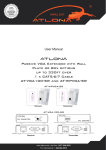
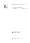
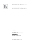
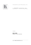
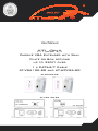
User Manual
AtlonA
Passive VGA Extender with Wall
Plate or Box options
up to 330ft over
1 x CAT5/6/7 Cable
AT-VGA100-SR and AT-WPVGA-SR
AT-WPVGA-SR
Receiver
Transmitter
AT-VGA100-SR
Receiver
Transmitter
TABLE OF CONTENTS
1. Introduction
..................................................
3
2. Package Contents
..................................................
3
3. Features
..................................................
3
4. Specification
..................................................
4
5. Connection and Operation
..................................................
4
6. Mode Selection
..................................................
5
7. Dip Switch
..................................................
5
8. Troubleshooting
..................................................
5
9. STP Connector
..................................................
6
10. Wiring Configuration
..................................................
7
11. Atlona Product Registration
..................................................
7
12. Safety Information
..................................................
8
13. Warranty
..................................................
9
2
INTRODUCTION
The Atlona passive VGA Extenders over 1 x CAT5/6/7 cable up to the distance of 330ft with resolutions
up to 1280x1024. The Atlona VGA Extenders are a perfect way of extending video signal away from the
computer. The advanced design allows no limitations or delays when using extender versus a direct
connection to the computer.
There extenders can be mixed and matched with each other. The wall plate transmitter can be matched
with “box” receiver and the other way around. Of course, the wall plate transmitter will perfectly work
with wall plate receiver and “box” transmitter with “box” receiver.
Combinations are below:
a. AT-WPVGA-S + AT-WPVGA-R
b. AT-VGA100-S + AT-VGA100-R
c. AT-WPVGA-S + AT-VGA100-R
d. AT-VGA100-S + AT-WPVGA-R
Plug and Play, no drivers or software needed, user will not even notice the difference when using an
extender versus a direct connection. The extenders required no external power.
The VGA Extenders are a great solution for many different applications, e.g., classroom, office environment, data-center, training room and many others where the computer must be placed further away
from the users display.
PACKAGE CONTENTS:
Depends on the package selected as this manual is for 6 models
• Module or 2 Modules – depending on the model purchased
• Instructions manual
• Wall plate Modules include white decora plate
FEATURES:
• Perfect for extending VGA signal further away than standard cables may allows.
• Extend signals up to 330ft away from the computer on a single low-cost Cat5, 6 or 7 cables.
• Wall plate transmitter is compatible with “box” receiver and other way around.
• Resolution support up to 1280x1024
• No power supplies are needed
• Plug and Play, no drivers or software needed
• Any computer is compatible, no limitations
3
SPECIFICATIONS:
Inputs
Outputs
VGA Type
VGA Resolution
Signal Bandwidth
Signal Loss
Transmitting Distance
Dimensions (inch)
Weight (lb)
Operation Temperature
AT-WPVGA-S
1 x VGA
1 x RJ45
AT-WPVGA-R
AT-VGA100-S
AT-VGA100-R
1 x RJ45
1 x VGA
1 x RJ45
1 x VGA
1 x RJ45
1 x VGA
(HD15) female
800x600, 1024x768, 1280x768 and 1280x1024
300 kHz max.
Less than 3dB per pair
up to 330ft (100m)
2.75x2.40x4.52 2.75x2.40x4.52 4.3x3.03x1.02
4.3x3.03x1.02
– Single Gang – Single Gang
0.15
Storage Temperature
Humidity
0 to 55oC
-20 to 85oC
up to 95%
Max. Distance via CAT5 Cable:
• 640x480 pixels (15MHz) – 430ft
• 800x600 pixels (30MHz) – 320ft
• 1024x768 pixels (60MHz) – 250ft
• 1280x1024 pixels (100MHz) – 200ft
CONNECTION AND OPERATION
• Connect transmitter module to the VGA connection of a computer
• Connect display to the receiver module
• Install or use pre-existing CAT5, 6 or 7 cables
• Make sure to use a cable tester to check all wires are correctly terminated. (Incorrect Termination
may cause damage to the receiving module)
• Once connected, please refer to the Mode and Dip switch configuration
Transmitter:
ANY TRANSMITTER
IS COMPATIBLE WITH
ANY RECEIVER
Receiver:
4
MODE SELECTION
Mode # 1: If your display is a projector or a new display 17-inch and up, please use Mode # 1
Mode # 2: If you are using a CRT monitor or a display under 17-inch, please switch to Mode # 2
DIP SWITCH
Filter
There are 5 dip-switchers on the receiving module. Each dip switch represents signal stability from 0
to 5, where #5 is the highest stability. The default mode is all dip-switchers are at the up position.
If the signal is going in and out or USB is freezing, please start by switching down the dip switch # 1,
if signal doesn’t become better, switch dip switch # 2 down and so on.
It is highly recommended using STP cable (Shielded Twisted Pair).
TROUBLESHOOTING
No Signal or it is going in and out:
a. Please test your RJ45 cables with a Fluke or similar tester to make sure that all the wires are connected and the distance is within the limits.
b. If you are using patch panel or and RJ45 wall plates, the distance will be reduced, please do a
direct connection bypassing all additional equipment.
c. Please try to re-terminate your CAT5/6/7 wire to 568B
d. Check the dip switch and mode configurations as they are very important when UTP wire is used.
e. Change the resolution on the computer to 800x600 or 1024x768
f. Change frequency to 60Hz
g. Try using STP Cable
Image is tilted:
a. Check the dip switch and mode configurations as they are very important when UTP wire is used.
b. Change the resolution on the computer to 800x600 or 1024x768
c. Change frequency to 60Hz
d. Try using STP Cable
If you are terminating STP cable with a plastic CAT5 or CAT6 connector, please separate ground wire
and connect it to the Ground connection on the receiver module.
STP (Shielded Twisted Pair) Cable is recommended
5
STP CONNECTOR
STP Connector is used:
Step # 1
ground cable
Shielded Twisted pair cable (STP cable)
ground cable (folded) - Must touch the Metal Housing
Step # 2
STP RJ45 connector (Metal Housing)
STP Connector is not used:
Step # 1
ground cable
Shielded Twisted pair cable (STP cable)
Step # 2
6
WIRING CONFIGURATION
RJ45 Pin Configuration: TIA/EIA 568B Wiring standard
Video Cable
1. Orange-white
2. Orange
3. Green-white
4. Blue
5. Blue-white
6. Green
7. Brown-white
8. Brown
Video Red +
Video Red H-Sync
Video Green +
Video Green V-Sync
Video Blue +
Video Blue -
Data Cable
1. Orange-white
2. Orange
3. Green-white
4. Blue
5. Blue-white
6. Green
7. Brown-white
8. Brown
Keyboard Clock
Keyboard Data
Power 1
Ground 1
Power 2
Ground 2
Mouse Clock
Mouse Data
ATLONA PRODUCT REGISTRATION
Thank you for purchasing this Atlona product — we hope you’ll enjoy it.
We also hope that you’ll take a few moments to register your new purchase. Registration creates an ownership
record if your product is lost or stolen and helps ensure you’ll receive notification of performance issues and firmware
updates.
At Atlona, we respect and protect your privacy and assure you that your registration information is completely
secure. Of course, Atlona product registration is totally voluntary and failure to register will not diminish your limited warranty rights.
7
SAFETY INFORMATION
Safeguards
To reduce the risk of electric shock, do not
expose this product to rain or moisture.
If the wall plug does not fit into your local
power socket, hire an electrician to replace
your obsolete socket.
Do not modify the wall plug.
Doing so will void the warranty and safety
features.
This equipment should be installed near
the socket outlet and the device should
be easily accessible in case it requires
disconnection.
Precautions
FCC Regulations state that any
unauthorized changes or modifications to
this equipment not expressly approved by
the manufacturer could void the
user’s authority to operate this
equipment.
Operate this product using only the
included external power supply. Use of
other power supplies could impair
performance, damage the product or cause
fires.
Avoid excessive humidity, sudden
temperature changes or temperature
extremes.
Keep this product away from wet locations
such as bathtubs, sinks, laundries, wet
basements and swimming pools.
Use only accessories recommended by
ATLONA to avoid fire, shock or other
hazards.
Unplug the product before cleaning. Use
a damp cloth for cleaning. Do not use
cleaning fluid or aerosols, which could
enter the unit and cause damage, fire or
electrical shock. Some substances may
also mar the finish of the product.
Never open or remove unit panels or make
any adjustments not described in this
manual. Attempting to do so could expose
you to dangerous electrical shock or other
hazards. It may also cause damage to your
AT-VGA100-SR and AT-WPVGA-SR. Opening the product will void the warranty.
Do not attempt to service the unit. Instead
disconnect it and contact your Authorized
ATLONA reseller or contact ATLONA
directly.
In the event of an electrostatic discharge,
this device may automatically turn off. If this
occurs, unplug the device, and plug it back
in.
Protect and route power cords so they will
not be stepped on or pinched by anything
placed on or against them. Be especially
careful of plug-ins, or cord exit points from
this product.
8
1. LIMITED WARRANTY
Atlona Technologies warrants that (a) its products (the “Product”) will perform substantially in accordance with the accompanying written materials for a period of 3 YEARS from the date of receipt and (b) that the Product will be free from
defects in materials and workmanship under normal use and service for a period of 3 years. In the event applicable law
imposes any implied warranties, the implied warranty period is limited to 3 years from the date of receipt. Some jurisdictions do not allow such limitations on duration of an implied warranty, so the above limitation may not apply to Customer.
2. CUSTOMER REMEDIES
Atlona Technologies and its suppliers’ entire liability and Customer’s exclusive remedy shall be, at Atlona Technologies’
option, either return of the price paid for the Product, or repair or replacement of the Product that does not meet this
Limited Warranty and which is returned to Atlona Technologies with a copy of Customer’s receipt. This Limited Warranty
is void if failure of the Product has resulted from accident, abuse, or misapplication. Any replacement Product will be warranted for the remainder of the original warranty period or 3 year, whichever is longer.
3. NO OTHER WARRANTIES
TO THE MAXIMUM EXTENT PERMITTED BY APPLICABLE LAW, ATLONA TECHNOLOGIES AND ITS SUPPLIERS
DISCLAIM ALL OTHER WARRANTIES, EITHER EXPRESS OR IMPLIED, INCLUDING, BUT NOT LIMITED TO IMPLIED WARRANTIES OF MERCHANTABILITY AND FITNESS FOR A PARTICULAR PURPOSE, WITH REGARD TO
THE PRODUCT AND ANY RELATED WRITTEN MATERIALS. THIS LIMITED WARRANTY GIVES CUSTOMER SPECIFIC LEGAL RIGHTS. CUSTOMER MAY HAVE OTHER RIGHTS DEPENDING ON THE JURISDICTION.
4. NO LIABILITY FOR DAMAGES
TO THE MAXIMUM EXTENT PERMITTED BY APPLICABLE LAW, IN NO EVENT SHALL ATLONA TECHNOLOGIES OR
ITS SUPPLIERS BE LIABLE FOR ANY DAMAGES WHATSOEVER (INCLUDING WITHOUT LIMITATION, SPECIAL, INCIDENTAL, CONSEQUENTIAL, OR INDIRECT DAMAGES FOR PERSONAL INJURY, LOSS OF BUSINESS PROFITS,
BUSINESS INTERRUPTION, LOSS OF BUSINESS INFORMATION, OR ANY OTHER PECUNIARY LOSS) ARISING
OUT OF THE USE OF OR INABILITY TO USE THIS PRODUCT, EVEN IF ATLONA TECHNOLOGIES HAS BEEN ADVISED OF THE POSSIBILITY OF SUCH DAMAGES. IN ANY CASE, ATLONA TECHNOLOGIES’ AND ITS SUPPLIERS’
ENTIRE LIABILITY UNDER ANY PROVISION OF THIS AGREEMENT SHALL BE LIMITED TO THE AMOUNT ACTUALLY PAID BY YOU FOR THE PRODUCT. BECAUSE SOME JURISDICTIONS DO NOT ALLOW THE EXCLUSION OR
LIMITATION OF LIABILITY FOR CONSEQUENTIAL OR INCIDENTAL DAMAGES, THE ABOVE LIMITATION MAY NOT
APPLY TO YOU.
9