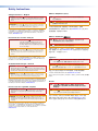
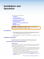
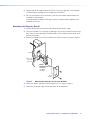
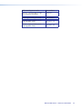
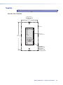
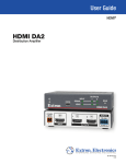
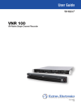
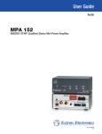
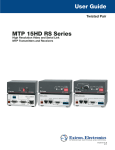
1
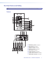
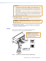
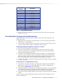
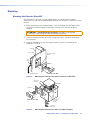
User Guide
Line Drivers
Extender Plus Series
VGA-UXGA Line Drivers with Audio
68-2320-01 Rev. A
12 12
Safety Instructions
Safety Instructions • English
WARNING: This symbol,
, when used on the product, is intended
to alert the user of the presence of uninsulated dangerous voltage
within the product’s enclosure that may present a risk of electric
shock.
Chinese Simplified(简体中文)
警告:
产品上的这个标志意在警告用户该产品机壳内有暴露的危险
电压,有触电危险。
注 意:
ATTENTION: This symbol,
, when used on the product, is intended
to alert the user of important operating and maintenance (servicing)
instructions in the literature provided with the equipment.
For information on safety guidelines, regulatory compliances, EMI/EMF
compatibility, accessibility, and related topics, see the Extron Safety and
Regulatory Compliance Guide, part number 68-290-01, on the Extron
website, www.extron.com.
Instructions de sécurité • Français
AVERTISSEMENT:Ce pictogramme,
, lorsqu’il est utilisé sur
le produit, signale à l’utilisateur la présence à
l’intérieur du boîtier du produit d’une tension
électrique dangereuse susceptible de provoquer
un choc électrique.
ATTENTION: Ce pictogramme,
, lorsqu’il est utilisé sur le produit,
signale à l’utilisateur des instructions d’utilisation ou de maintenance
importantes qui se trouvent dans la documentation fournie avec le
matériel.
Pour en savoir plus sur les règles de sécurité, la conformité à la
réglementation, la compatibilité EMI/EMF, l’accessibilité, et autres sujets
connexes, lisez les informations de sécurité et de conformité Extron, réf.
68-290-01, sur le site Extron, www.extron.fr.
产 品 上 的 这个 标 志 意 在 提 示用 户设 备 随 附 的 用 户手 册 中 有
重要的操作和维护(维修)说明。
关于我们产品的安全指南、遵循的规范、EMI/EMF 的兼容性、无障碍
使用的特性等相关内容,敬请访问 Extron 网站 www.extron.com,参见 Extron
安全规范指南,产品编号 68-290-01。
Chinese Traditional(繁體中文)
警告:
若產品上使用此符號,是為了提醒使用者,產品機殼內存在著
可能會導致觸電之風險的未絕緣危險電壓。
注意
若產品上使用此符號,是為了提醒使用者。
有關安全性指導方針、法規遵守、EMI/EMF 相容性、存取範圍和相關主題的詳細
資訊,請瀏覽 Extron 網站:www.extron.com,然後參閱《Extron 安全性與法
規遵守手冊》,準則編號 68-290-01。
Japanese
警告: この記号
が製品上に表示されている場合は、筐体内に絶縁されて
いない高電圧が流れ、感電の危険があることを示しています。
Sicherheitsanweisungen • Deutsch
WARNUNG: Dieses Symbol
auf dem Produkt soll den Benutzer
darauf aufmerksam machen, dass im Inneren des Gehäuses dieses
Produktes gefährliche Spannungen herrschen, die nicht isoliert sind
und die einen elektrischen Schlag verursachen können.
VORSICHT: Dieses Symbol
auf dem Produkt soll dem Benutzer in
der im Lieferumfang enthaltenen Dokumentation besonders wichtige
Hinweise zur Bedienung und Wartung (Instandhaltung) geben.
Weitere Informationen über die Sicherheitsrichtlinien, Produkthandhabung,
EMI/EMF-Kompatibilität, Zugänglichkeit und verwandte Themen finden Sie
in den Extron-Richtlinien für Sicherheit und Handhabung (Artikelnummer
68-290-01) auf der Extron-Website, www.extron.de.
注意: この記号
が製品上に表示されている場合は、本機の取扱説明書に記載されて いる
重要な操作と保守(整備)の指示についてユーザーの注意を喚起するものです。
安全上のご注意、法令遵守、EMI/EMF適合性、その他の関連項目に
ついては、エクストロンのウェブサイトwww.extron.comより
『 Extron Safety and Regulatory Compliance Guide』 (P/N 68-290-01) をご覧く
ださい。
Korean
경고: 이 기호
, 가 제품에 사용될 경우, 제품의 인클로저 내에 있는
접지되지 않은 위험한 전류로 인해 사용자가 감전될 위험이 있음을
경고합니다.
Instrucciones de seguridad • Español
ADVERTENCIA: Este símbolo,
, cuando se utiliza en el producto,
avisa al usuario de la presencia de voltaje peligroso sin aislar dentro
del producto, lo que puede representar un riesgo de descarga
eléctrica.
ATENCIÓN: Este símbolo,
, cuando se utiliza en el producto, avisa
al usuario de la presencia de importantes instrucciones de uso y
mantenimiento recogidas en la documentación proporcionada con
el equipo.
Para obtener información sobre directrices de seguridad, cumplimiento
de normativas, compatibilidad electromagnética, accesibilidad y temas
relacionados, consulte la Guía de cumplimiento de normativas y seguridad
de Extron, referencia 68-290-01, en el sitio Web de Extron,
www.extron.es.
주의:
이 기호
, 가 제품에 사용될 경우, 장비와 함께 제공된 책자에 나와
있는 주요 운영 및 유지보수(정비) 지침을 경고합니다.
안전 가이드라인, 규제 준수, EMI/EMF 호환성, 접근성, 그리고 관련
항목에 대한 자세한 내용은 Extron 웹 사이트(www.extron.com)의
Extron 안전 및 규제 준수 안내서, 68-290-01 조항을 참조하십시오.
Conventions Used in this Guide
The following notifications are used:
CAUTION:
A caution indicates a situation that may result in minor injury.
ATTENTION: Attention indicates a situation that may damage or destroy the product or
associated equipment.
NOTE: A note draws attention to important information.
Specifications Availability:
Product specifications are available on the Extron website, www.extron.com.
Copyright
© 2012 Extron Electronics. All rights reserved.
Trademarks
All trademarks mentioned in this guide are the properties of their respective owners.
Contents
Introduction............................................................ 1
Reference Information....................................... 13
About this Guide.................................................. 1
About the Extender Plus Series
VGA Line Drivers................................................ 1
Differences between the models...................... 1
Features.......................................................... 1
Part Numbers.................................................... 13
Included Parts............................................... 13
Accessories................................................... 13
Dimensions....................................................... 15
Template........................................................... 16
Installation and Operation................................... 2
Extron Warranty
UL Guidelines...................................................... 2
Installation Instructions........................................ 2
Preparing the Site and
Installing the Wall Box..................................... 2
Front Panel Features and Cabling........................ 4
Rear Panel Features and Cabling......................... 5
Features.......................................................... 5
Cabling............................................................ 7
EDID Minder Operation........................................ 8
Storing a display EDID..................................... 8
Using the pre-programmed Extron EDID.......... 8
Pre-Installation Testing and
Troubleshooting.................................................. 9
Mounting........................................................... 10
Mounting the Extender Plus AAP................... 10
Mounting the Extender Plus D....................... 11
Application Diagrams......................................... 12
Extender Plus Series • Contents
v
Introduction
This section covers the following topics:
•
About this Guide
•
About the Extender Plus Series VGA Line Drivers
About this Guide
This guide contains information about the Extron Extender Plus Series line drivers, and
instructions for operation and configuration. “Extender” and “line driver” are used to refer to
the models interchangeably when instructions apply to both models.
About the Extender Plus Series VGA Line Drivers
The Extron Extender Plus Series are one-input VGA‑QXGA line drivers with audio and
EDID Minder® capability. There are two models in the series:
•
Extender Plus AAP
•
Extender Plus D
The Extenders boost the video signal between a laptop or desktop computer and a monitor
or projector. Each has a 400 MHz (-3 dB) video bandwidth.
Each line driver accepts one computer video input and one stereo audio input. Each
Extender also features one buffered VGA-type RGB output and one stereo audio output.
With an optional Mac/VGA adapter, the Extender can also buffer Macintosh signals.
Differences between the models
Both Extender Plus models are functionally identical but they have different mounting
options.
For details about mounting the Extender Plus AAP, and the Extender Plus D, see
“Preparing the Site and Installing the Wall Box” on the next page.
Features
Video signal boosting — The selectable gain setting boosts video signals to compensate
for signal degradation caused by long cables. The Extender can send a high resolution
signal up to 250 feet (75 m) through Extron M59 Series mini high resolution cable.
Sync restoration — Each Extender restores low level sync voltages found on many laptop
PCs (as low as two volts) to normal TTL levels.
Audio buffering — Unbalanced stereo audio inputs can be output as balanced audio for
long cable runs.
EDID Minder — EDID Minder is available for VGA signals, allowing the EDID of any VGA
display to be stored and emulated, or any of 14 pre-installed factory EDID files to be
selected and presented to the source.
Extender Plus Series • Introduction
1
Installation and
Operation
This section covers the following topics:
•
UL Guidelines
•
Installation Instructions
•
Front Panel Features and Cabling
•
Rear Panel Features and Cabling
•
EDID Minder Operation
•
Pre-Installation Testing and Troubleshooting
•
Mounting
•
Application Diagrams
ATTENTION: Potential damage to property. Installation and service must be
performed by authorized personnel only (see “Installation Instructions,” below). Use a
UL-approved electrical box (see “UL Guidelines,” below).
UL Guidelines
1. The Extender must be installed in an Underwriters Laboratories (UL) listed junction box.
The UL-approved electrical wall box (junction box) is not included with the unit; the
installer is responsible for obtaining and installing the box.
2. The unit must be installed in accordance with the National Electrical Code and with local
electrical codes.
Installation Instructions
Depending on the model, the Extenders can be mounted into furniture, a wall, an
Ackermann floorbox, or an Extron HSA 400 Series or HSA 800 Series enclosure.
Preparing the Site and Installing the Wall Box
Considerations
Choose a location that allows cable runs without interference. Allow enough depth for both
the wall box and the cables. You may need to install the cables into the wall, furniture, or
conduits before installing the line driver.
•
The Extender Plus AAP can be installed in an Extron two-gang, four-gang, or half rack
width AAP Architectural Adapter Plate or in the faceplate of another Extron device that
accepts double-space AAPs, such as an interface or distribution amplifier. See the
mounting instructions for the adapter plate or device.
•
The Extender Plus D can be installed in a standard or compact one-gang wall box
The installation must conform to national and local electrical codes and to the size
requirements of the Extender. See the Extender Plus D “Dimensions” on page 15 and
“Template” on page 16.
Extender Plus Series • Installation and Operation
2
Procedure
1. See the template that corresponds to the wall box being used.
NOTE:The templates are not shown at full size. Pay attention to the measurements shown on the templates.
2. Mark the guidelines for the opening on the wall or furniture.
• If installing the Extender in a wall box, place the box against the installation surface
and draw a line on it around the outside of the box.
• If installing the Extender without a wall box (using mud rings or fastening it directly
to the wall or furniture), measure and mark the surface for the cutout area indicated
in the template.
3. Cut out the material from the marked area.
4. Check the opening size by inserting the wall box (if used) or the Extender (if no box is
used) into the opening. The box and line driver should fit easily into the opening. Enlarge
or smooth the edges of the opening if needed.
5. Feed cables through the wall box punch-out holes, and secure them with cable clamps
to provide strain relief.
6. Trim back and insulate foil or braided shields with heat shrink (see figure 1).
Connecting Shields.eps
ATTENTION: Potential damage to property. Exposed cable shields (braids or
foil) can cause short circuits. To prevent short circuits, cut back the outer foil shield
to the point where the cable exits the cable clamp. Both braided and foil shields
should be connected to an equipment ground at the other end of the cable.
Metal Wall Box
Screw
Cable Clamp
Braided Shield
Install Cable
Foil Shield
Figure 1.
1-gang wall box.eps
Grounding Outer Braided and Foil Shields
7. Insert the wall box into the opening, and attach it to the wall, stud, or furniture.
• If installing the Extender in a two- or four-gang AAP plate, use nails or screws to
attach the wall box to the wall stud or furniture, leaving the front edge of the wall
box flush with the outer wall or furniture surface. See figure 2, which applies to one,
two-, three-, and four-gang wall boxes.
Wall Stud
Installation Cable
Wall Stud
Installation Cable
Cable Clamp
Cable Clamp
Screws or Nails
Screws or Nails
Figure 2.
Attaching a Wall Box to a Wall Stud
Extender Plus Series • Installation and Operation
3
•
If attaching the wall box to wood, use four #8 or #10 screws or 10-penny nails. A
minimum of ½ inch (1.3 cm) of screw threads must penetrate the wood.
•
If attaching the wall box to metal studs or furniture, use four #8 or #10 self-tapping
sheet metal screws or machine bolts with matching nuts.
8. Set the gain switch, then cable and test the line driver before fastening the line driver
into the wall box. The switch and cables are not accessible after installation.
See “Rear Panel Features and Cabling” on page 5 for details.
Front Panel Features and Cabling
AUDIO IN
AUDIO IN
COMPUTER IN
1
2
EXTENDER Plus AAP
COMPUTER IN
3
a Power/signal LED — This LED lights:
•
Amber to indicate that the Extender is receiving power.
•
Green to indicate that an active signal with separate horizontal sync is present at
the input and the Extender is receiving power.
NOTE: The LED remains lit amber when the input signal is HDTV component video, RGsB, or RsGsBs.
b Audio input connector — Plug a 3.5 mm stereo plug into this
jack for unbalanced audio input. Wire the male plug as shown at
right.
c Computer In connector (RGB video) — Attach a cable
from the computer to the Extender via this female 15-pin HD
connector.
Tip (L)
Ring (R)
Sleeve ( )
3.5 mm Stereo Plug
Connector
(unbalanced)
Extender Plus Series • Installation and Operation
4
Rear Panel Features and Cabling
NOTE: Mount the Extender Plus AAP to a wall plate or device faceplate before the final cabling.
Features
2
A
3 4 56
BCDE
F 0 1
6
7 8 9
60
50
Hz
7
ON
1
2
EDID
2
POWER
12V
0.2 A MAX
SELECT
1
3
NORM
MED
HIGH
COMPUTER
OUT
EXTENDER Plus D
GAIN
8
5
4
3
1
2
EXTENDER Plus AAP
EDID
SELECT
STORE
50
BCD
6
60
F 0 12
AUDIO OUT
R
L
E
Hz
7 8 9A
MED
NORM
HIGH
GAIN
COMPUTER
OUT
3 4 5
5
L
R
AUDIO OUT
STORE
4
POWER
12V
0.2 A MAX
6
7
8
a
b
c
d
e
f
g
h
EDID Rotary switch (see page 6)
Dip switches (see page 6)
EDID store LED (see page 6)
EDID store button (see page 6)
Gain switch (see page 6)
Power connector (see page 6)
Audio output connector (see page 7)
RGB output connectors (see page 7)
Extender Plus Series • Installation and Operation
5
a EDID Rotary Switch — Position 0 of this 16-position rotary switch is used to record an
EDID from a display. See “Storing a display EDID” on page 8.
Positions 1 through F select pre‑programmed EDID resolutions. See “Using the
pre-programmed Extron EDID” on page 8.
bDIP switch — Position 1 selects the vertical refresh frequency for the pre-programmed
EDID. When switched to Off, the EDID selected by rotary positions 1 through F are
based on 50 Hz. When switched to On, they are based on 60 Hz (default position).
Position 2 is not used.
NOTE: Configuring the EDID rotary and DIP switches allows a user to select a
pre-programmed EDID based on the native rate of a display (for example, 1280x1024 @
60 Hz) and a desired signal type (such as digital), but does not necessarily force a video
source to output that rate. Since EDID is not limited to reporting a single video rate
(such as the native rate), each Extron EDID also lists other common video rates that the
video source can use.
c
EDID Store LED — This dual color LED:
•
Lights green to indicate that the Extender is receiving power.
•
Flashes red when EDID is being stored (after the EDID store button has been
pressed), returning to green when EDID storing is complete.
d
EDID Store button — Press this recessed push button to initiate EDID storage from
a display (temporarily) connected to the VGA input. The EDID is stored to the user
slot (position 0 on the rotary switch). While EDID is being stored, the LED flashes
red, returning to green when storage is complete. The VGA display must then be
disconnected from the VGA input for installation. See “Storing a display EDID” on
page 8 for more details.
e
Gain switch — Use this switch to compensate for cable resistance and capacitance.
Using an Extron Tweeker or a small screwdriver, slide this switch to select the level of
video gain that yields the sharpest, smear-free picture.
•
Normal — Unity gain (no signal boost)
•
Medium — Mid-level peaking and gain
•
High — Maximum amount of peaking and gain. Select this for use with longer
cables.
NOTE: Adjust the gain before installing the Extender into a wall, furniture, or
equipment, as the gain switch is not accessible after installation.
3.5 mm, 2-pole direct insertion captive screw connector. Wire the
connector as shown at right.
12 VDC
–
+
Power
f Power connector — Connect a 12 VDC power supply to this
Do not tin the wires!
ATTENTION: Potential damage to property.
• Do not tin the wires. For best results and to reduce the risk of short circuits, trim
just 3/16 inch (5 mm) of the jacket from the wires.
• Always use a power supply supplied by or specified by Extron. Use of an
unauthorized power supply voids all regulatory compliance certification and may
cause damage to the supply and the end product.
Extender Plus Series • Installation and Operation
6
ATTENTION:
• Unless otherwise stated, the AC/DC adapters are not suitable for use in air
handling spaces or in wall cavities. The power supply is to be located within the
same vicinity as the Extron AV processing equipment in an ordinary location,
Pollution Degree 2, secured to the equipment rack within the dedicated closet,
podium or desk.
• The installation must always be in accordance with the applicable provisions of
National Electrical Code ANSI/NFPA 70, article 75 and the Canadian Electrical
Code part 1, section 16. The power supply shall not be permanently fixed to
building structure or similar structure.
g Audio output connector — Insert wires into and tighten the screws on this 3.5 mm,
5-pole direct insertion captive screw connector for unbalanced or balanced audio
output. Wire the connector as shown in figure 3.
ATTENTION: Potential damage to property. Connect the sleeve to the ground
(Gnd) terminal. Connecting the sleeve to a negative (-) terminal will damage the
audio output circuits.
h RGB video output connectors — Attach coaxial cables from the Extender to the
display device via these female BNC connectors. These BNCs are on pigtail wires
secured to the Extender by tie wrap.
Cabling
Figure 3 shows the Extender Plus AAP wired for balanced audio output.
The Extender Plus D has the same circuit board configuration.
CT
LE
SE
9 A
78
R
WE
PO
V
AX
12 A M
0.2
Power
T
OU
R
Audio
12 VDC
R
50
6
2
4 5
DIO
AU
1
2
R
L
L
E
UT
MP
CO OUT
E
OR
ST
1
EX
Plu GAIN
NORM
MED
HIGH
R
DE
N
TE
CDE
F0
60
Hz
ON
sD
B
3
ID
ED
ATTENTION: Potential damage to
property. For unbalanced audio,
connect the sleeve(s) to the ground
contact. DO NOT connect the sleeve(s)
to the negative (-) contacts.
Audio
Unbalanced Output
L
Audio
R
Right Ring
Right Tip
Sleeve (s)
Left Ring
Left Tip
NO Ground Here
Right Tip
Sleeve (s)
NO Ground Here
Left Tip
Right Ring
Right Tip
Sleeve (s)
Left Ring
Left Tip
Balanced Output
Do not tin the wires!
Figure 3.
Extender Plus AAP Wired for Balanced Audio Output
Extender Plus Series • Installation and Operation
7
EDID Minder Operation
EDID Minder enables continuous EDID communication to the input source. EDID provides
information about a display identity. The continuous EDID communication ensures the
source boots up properly and outputs content to the display reliably.
The Extender Plus models offer two ways of doing this:
•
EDID Record — Enables the device to record EDID directly from a display. See
“Storing a display EDID” below.
•
Pre-programmed EDID — The Extender Plus models contain pre‑programmed EDIDs
with the most common display native resolutions for both 50 and 60 Hz. Along with the
native rate, each pre-programmed EDID also lists other common video rates that the
video source can use. See “Using the pre-programmed Extron EDID” below.
Storing a display EDID
To store a new EDID into the memory:
1. Turn the rotary switch to position 0.
NOTE: The DIP switch positions have no effect in this mode.
2. Apply power to the Extender by connecting the 12 VDC power supply. The EDID Store
LED lights green when power is available.
3. Connect the display device to the input of the Extender using a VGA cable.
4. Power on the display device.
5. Press and release the recessed EDID store button. The EDID Store LED flashes red
while storing the EDID, then turns solid green when the EDID data has been stored. The
display and the power supply can now be disconnected.
Using the pre-programmed Extron EDID
NOTE: Configuring the EDID rotary and DIP switches allows a user to select a
pre-programmed EDID based on the native rate of a display (for example, 1280x1024 @
60 Hz) and a desired signal type (such as digital), but does not necessarily force a video
source to output that rate. Since EDID is not limited to reporting a single video rate
(such as the native rate), each Extron EDID also lists other common video rates that the
video source can use.
1. See Table 1 on the next page to see which resolution corresponds to each rotary
switch position (1-F). Select the rotary switch position that corresponds to the native
resolution of the display.
2. To use the EDID, set the rotary switch to the position selected in step 1. The switch
clicks as it moves through the positions.
Extender Plus Series • Installation and Operation
8
Rotary Switch
Position
0
1
2
3
4
5
6
7
8
9
A
B
C
D
E
F
Resolution
User-Recorded EDID
800x600
1024x768
1280x720
1280x768
1280x800
1280x1024
1360x768
1366x768
1400x1050
1440x900
1600x1200
1680x1050
1920x1080
1920x1200
N/A
Table 1 — Rotary Switch Position
3. Set the first DIP switch based on the vertical refresh of the native rate of the display
(default is On, 60 Hz).
Pre-Installation Testing and Troubleshooting
Before mounting the line driver, test the system to make sure that the connections and
settings are correct.
1. Apply power to the line driver. The power/signal LED on the line driver lights amber to
indicate that it is receiving power.
2. If the LED does not light, check the wiring at both the line driver and the power supply,
and make sure the power supply is connected to a power source.
If the image does not appear or there is no sound
1. Make sure that all the devices are powered on.
2. Ensure that the connectors are wired correctly at both ends of the cables. Audio
cables must be wired for an unbalanced stereo input signal and for the appropriate
(unbalanced or balanced) output signal.
3. If the input is from a laptop computer and no picture appears, use a laptop breakout
cable for the input connection. Check the computer user guide or contact Extron to
determine if special commands are required to output video to the external video port.
Also, many laptop screens shut off after the external video port is activated.
4. Call the Extron S3 Sales and Technical Support Hotline if the image still does not appear
or there is no sound.
If the image is not displayed correctly
1. If the picture is too bright or too dark, if the edges of the image seem to exceed their
boundaries, or if thin lines and sharp edges look thick and fuzzy, change the gain
setting. See the Gain switch, item e on page 6.
2. If the picture appears and is stable, but it has ghosting or blooming, verify that the video
input is properly terminated. If this does not resolve the problem, try using a different
input cable. Poor quality or damaged cable can cause ghosting and blooming.
3. If the picture still fails to display correctly, call the Extron S3 Sales and Technical Support
Hotline.
Once the system has been cabled and tested, the line driver can be installed in the wall,
furniture, or equipment.
Extender Plus Series • Installation and Operation
9
Mounting
Mounting the Extender Plus AAP
The Extender Plus AAP and any other adapter plates must be attached to a device
faceplate or AAP wall plate and cabled before the device or wall plate is installed in a wall or
furniture.
1. Before attaching any user-supplied cables, insert the Extender Plus AAP output BNC
connectors and wires through the opening in the front of the wall plate or device
faceplate.
ATTENTION: Potential damage to property. Be careful not to damage
connectors while placing the Extender through the opening.
2. Insert the threaded standoffs of the AAP through the holes in the device faceplate or
AAP wall plate.
3. Using the provided #4-40 nuts and captive washers, secure the Extender to the
faceplate or wall plate.
Wall Stud
Screws or Nails
#4-40 Nut w/ Captive
Washer
Cable
Clamp
AAP 102
2
P 10
AA
R IN
TE
MPU
CO
DIO
us
P Pl
IN
ER
AA
ND
AU
TE
EX
Extender Plus AAP
Installation Cable
Figure 4.
Mounting the Extender Plus AAP to a Device or Wall Plate
Two Screws
Each Side
HSA 822
Front Panel
AU
DIO
HS
A 82
IN
2
CO
MP
UT
EX
ER
TE
IN
ND
ER
AA
PP
lus
Extender Plus AAP
#4-40 Nut
w/ Captive
Washer
Connects to
AAP Cable
Figure 5.
Mounting the Extender Plus AAP to an HSA Faceplate
Extender Plus Series • Installation and Operation
10
4. Repeat steps 1, 2, and 3 to mount other AAPs. Cover any openings in the faceplate
with blank plates (provided with the faceplate or HSA device).
5. Be sure to include the AAP connectors as part of the installation pretest before final
installation of the faceplate.
For more detailed installation information, see the installation guide shipped with the
faceplate or the HSA.
Mounting the Extender Plus D
1. Remove power from the line driver by disconnecting the power supply.
2. Place the Extender Plus D through the opening in the wall or furniture and into the wall
box. Take care not to damage the output cables, which fit behind the line driver at the
back of the wall box.
3. Mount the Extender Plus D to the wall box with machine screws as shown in figure 6.
Wall Box
Wall opening
is flush with
edge of box.
IN
IO
D
AU
ER
UT
P
OM
IN
C
Extron
Extender Plus D
VGA-QXGA
Line Driver
with Audio
Decora
Wall Plate
Figure 6.
Mounting the Extender Plus D to the Wall Box
4. Attach the Decora® wall plate to the Extender Plus D as shown in figure 6.
5. Reconnect the power supply and restore power to the equipment.
Extender Plus Series • Installation and Operation
11
Application Diagrams
Mini HR Cable
Projector
Wall Stud
Audio
DIO
IN
AU
R IN
TE
MPU
CO
Laptop
w/ Audio
Extender Plus D
Mini HR
Cable
Projector
Laptop w/ Audio
R IN
TE
MPU
CO
DIO
Extender Plus AAP
us
P Pl
IN
AU
ER
AA
ND
TE
EX
ED
ER ITOR
FF
BU MON
L
CA
LO
IFT
H.
8
SH
TO
AU
R
WE
PO
B 56
RG
T
PU
IN
DIO
AU
11
PIN
ID N 4
PI
ID
CS
PIN
9
RGB 468
SVGA Compatible
Computer w/ Audio
Extender Plus Series • Installation and Operation
12
Reference
Information
This section contains the following information:
•
Part Numbers
•
Dimensions
•
Template
Part Numbers
Included Parts
Part numbers
Extender Plus D (white)
60-1261-22
Extender Plus AAP (black)
60-1262-12
Extender Plus AAP (white)
60-1262-22
Included Parts
This section lists part numbers for each Extender and Extender kit.
Included Parts (Extender Plus D)
Part numbers
1 gang mud ring / mounting bracket
(black, white)
Decora wall plate, 1 gang, white
12 VDC, 1.0 A external power supply
70-775-01
IEC cord
Extender Plus Series Setup Guide
Included Parts (Extender Plus AAP) Part numbers
12 VDC, 1.0 A external power supply
70-775-01
IEC cord
Extender Plus Series Setup Guide
Accessories
AAP mounting accessories
Part numbers
AAP 102 – 2 gang wall plate (black,
white)
60-300-02, -03
AAP 104 – 4 gang wall plate (black,
white)
60-301-02, -03
Extender Plus Series • Reference Information
13
AAP mounting accessories
Part numbers
AAP 201 – half rack wide, 1U high
AAP mounting frame (black)
60-302-02
Mud rings/mounting brackets
Part numbers
MR 100 – 1-gang modular plastic
mud ring (black, white)
70-519-12, -13
MR 300 – 3-gang modular plastic
mud ring (black, white)
70-519-32, -33
Extender Plus Series • Reference Information
14
Dimensions
NOTE: The drawings in this section are not full size. Do not scale.
Extender Plus D Dimensions
1.35"
(34.3 mm)
Both Ends
0.10" (2.5 mm)
4.10"
(104.14 mm)
2.70"
(68.6 mm)
2.62"
(66.5 mm)
1.29"
(32.8 mm)
1.37"
(34.8 mm)
Side View
Front View
Extender Plus Series • Reference Information
15
Template
NOTE: The drawing below is not full size. Do not scale.
Extender Plus D Template
Cut-Out Template for
Extender Plus D
(Front View)
2.79"
(7.09 cm)
Top Panel
1.44"
(36.6 mm)
4.50"
(11.43 cm)
2.83"
(71.9 mm)
Location of
Extender Plus D
SURFACE
CUT-OUT AREA
FOR
FURNITURE
MOUNT
To install an
Extender Plus D
directly into
furniture or wall,
cut along this line.
Extender Plus Series • Reference Information
16
Extron Warranty
Extron Electronics warrants this product against defects in materials and workmanship for a period of three years
from the date of purchase. In the event of malfunction during the warranty period attributable directly to faulty
workmanship and/or materials, Extron Electronics will, at its option, repair or replace said products or components,
to whatever extent it shall deem necessary to restore said product to proper operating condition, provided that it is
returned within the warranty period, with proof of purchase and description of malfunction to:
USA, Canada, South America,
and Central America:
Extron Electronics
1230 South Lewis Street
Anaheim, CA 92805
U.S.A.
Japan:
Extron Electronics, Japan
Kyodo Building, 16 Ichibancho
Chiyoda-ku, Tokyo 102-0082
Japan
Europe and Africa:
Extron Europe
Hanzeboulevard 10
3825 PH Amersfoort
The Netherlands
China:
Extron China
686 Ronghua Road
Songjiang District
Shanghai 201611
China
Asia:
Extron Asia
135 Joo Seng Road, #04-01
PM Industrial Bldg.
Singapore 368363
Singapore
Middle East:
Extron Middle East
Dubai Airport Free Zone
F12, PO Box 293666
United Arab Emirates, Dubai
This Limited Warranty does not apply if the fault has been caused by misuse, improper handling care, electrical
or mechanical abuse, abnormal operating conditions, or if modifications were made to the product that were not
authorized by Extron.
NOTE: If a product is defective, please call Extron and ask for an Application Engineer to receive an RA (Return
Authorization) number. This will begin the repair process.
USA: 714.491.1500 or 800.633.9876
Asia:65.6383.4400
Europe:31.33.453.4040
Japan:81.3.3511.7655
Units must be returned insured, with shipping charges prepaid. If not insured, you assume the risk of loss or damage
during shipment. Returned units must include the serial number and a description of the problem, as well as the
name of the person to contact in case there are any questions.
Extron Electronics makes no further warranties either expressed or implied with respect to the product and its quality,
performance, merchantability, or fitness for any particular use. In no event will Extron Electronics be liable for direct,
indirect, or consequential damages resulting from any defect in this product even if Extron Electronics has been
advised of such damage.
Please note that laws vary from state to state and country to country, and that some provisions of this warranty may
not apply to you.
Extron Headquarters
+1.800.633.9876 (Inside USA/Canada Only)
Extron USA - West
Extron USA - East
+1.714.491.1500+1.919.850.1000
+1.714.491.1517 FAX
+1.919.850.1001 FAX
Extron Europe
+800.3987.6673
(Inside Europe Only)
+31.33.453.4040
+31.33.453.4050 FAX
Extron Asia
+800.7339.8766
(Inside Asia Only)
+65.6383.4400
+65.6383.4664 FAX
Extron Japan
+81.3.3511.7655
+81.3.3511.7656 FAX
© 2012 Extron Electronics All rights reserved.
Extron China
+4000.398766
Inside China Only
+86.21.3760.1568
+86.21.3760.1566 FAX
Extron Middle East
+971.4.299.1800
+971.4.299.1880 FAX
www.extron.com
Extron Korea
+82.2.3444.1571
+82.2.3444.1575 FAX
Extron India
1800.3070.3777
Inside India Only
+91.80.3055.3777
+91.80.3055.3737 FAX