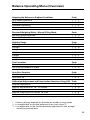
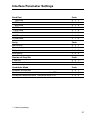
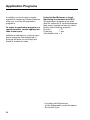
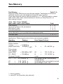
1
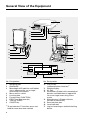
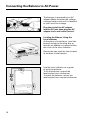
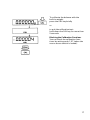
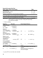
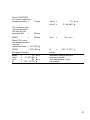
TB Series
TB-Serie
Electronic Analytical and Precision Balances
Elektronische Analysen- und Präzisionswaagen
Operating Instructions / Betriebsanleitung
Contents
Page
General View of the Equipment . . . . . . . . . . . . . . . . . . . . . . . . . . . . . . . . . . . . . . 4
Getting Started . . . . . . . . . . . . . . . . . . . . . . . . . . . . . . . . . . . . . . . . . . . . . . . . . . . . 5
Installation Instructions . . . . . . . . . . . . . . . . . . . . . . . . . . . . . . . . . . . . . . . . . . . . . 6
Connecting the Balance to AC Power . . . . . . . . . . . . . . . . . . . . . . . . . . . . . . . . . 10
Operating the Balance . . . . . . . . . . . . . . . . . . . . . . . . . . . . . . . . . . . . . . . . . . . . . . 12
Calibration/Adjustment . . . . . . . . . . . . . . . . . . . . . . . . . . . . . . . . . . . . . . . . . . . . . 14
Data Interface Port . . . . . . . . . . . . . . . . . . . . . . . . . . . . . . . . . . . . . . . . . . . . . . . . . 18
Below-Balance Weighing . . . . . . . . . . . . . . . . . . . . . . . . . . . . . . . . . . . . . . . . . . . 19
Troubleshooting . . . . . . . . . . . . . . . . . . . . . . . . . . . . . . . . . . . . . . . . . . . . . . . . . . . 20
Care and Maintenance . . . . . . . . . . . . . . . . . . . . . . . . . . . . . . . . . . . . . . . . . . . . . . 21
Configuring the Balance . . . . . . . . . . . . . . . . . . . . . . . . . . . . . . . . . . . . . . . . . . . . 22
Balance Operating Menu (Overview) . . . . . . . . . . . . . . . . . . . . . . . . . . . . . . . . . . 25
Application Programs . . . . . . . . . . . . . . . . . . . . . . . . . . . . . . . . . . . . . . . . . . . . . . 30
GLP/GMP-compliant Data Record . . . . . . . . . . . . . . . . . . . . . . . . . . . . . . . . . . . . 42
Specifications . . . . . . . . . . . . . . . . . . . . . . . . . . . . . . . . . . . . . . . . . . . . . . . . . . . . . 46
Declarations of Conformity . . . . . . . . . . . . . . . . . . . . . . . . . . . . . . . . . . . . . . . . . . 49
3
General View of the Equipment
1
15
5
4
14
12
16
17
16
1
2
15
14
13
3
12
4
5
11
3
6
10
7
8
9
No. Designation
No. Designation
1
2
3
10
4
5
6
7
8
9
1)
4
Weighing pan
Shield disk
Metrological ID label for verified balances approved for use as legal
measuring instruments
Menu access switch
Leveling foot
Function key (FUNCTION)
PRINT key (data transfer)
Tare key (TARE)
ON/OFF key
To activate the CF function, press and
hold for more than two seconds
11
12
13
14
15
16
17
CAL/CF key
(calibration/clear function)1)
Weight display
AC jack
Verification ID label with metrological
data for verified balances approved
for use as legal measuring instruments
Manufacturer’s ID label with the
C mark of conformity
Data interface port
Level indicator
Lug for fastening an antitheft locking
device
Getting Started
The DENVER INSTRUMENT GMBH
product you have purchased meets
high quality standards and is
designed to assure many years of
trouble-free service.
Please read these operating
instructions carefully before you
begin to operate your new balance.
Warranty
In the unlikely event that your
balance should require servicing
within the 3-year warranty period,
please contact the office listed below
for your country, and state the model
number, serial number and the
problem:
Federal Republic of Germany:
DENVER INSTRUMENT GMBH
Robert-Bosch-Breite 10
37079 Goettingen, Germany
Phone (+49/551) 209773-0
Telefax (+49/551) 209773-9
Internet:
http://www.denverinstrument.com
E-mail: [email protected]
Storage and Shipping Conditions
Allowable storage temperature:
+5°C … +40°C
+41°F…+104°F
Unpacking the Balance
● After unpacking the balance,
check it immediately for any visible
damage as a result of rough handling
during shipment.
$ If you see any sign of damage,
proceed as directed in the chapter
entitled “Care and Maintenance,”
under the section on “Safety
Inspection.”
Save the box and all parts of the
packaging until you have successfully
installed your balance. Only the
original packaging provides the best
protection for shipment. Before
packing your balance, unplug all
connected cables to prevent damage.
5
Installation Instructions
Ambient Conditions
The Denver Balance is designed to
provide reliable weighing results
under normal ambient conditions in
the laboratory and in industry.
When choosing a location to set
up your balance, please observe the
following so that you will be able to
work with added speed and accuracy:
– Set up the balance on a stable,
even surface
– Protect the balance from aggressive
chemical vapors
– Protect the balance from drafts
that come from open windows and
doors
– Avoid exposing the balance to
extreme vibrations
– Avoid exposing the balance to
extreme heat or to direct sunlight
Conditioning the Balance
Do not expose the balance to
extreme moisture over long periods.
Moisture in the air can condense on
the surfaces of a cold balance whenever it is brought to a substantially
warmer place. If you transfer the balance to a warmer area, make sure to
condition it for about 2 hours at the
new ambient temperature, leaving
it unplugged from the power supply.
Afterwards, if you keep the balance
connected to the power supply,
the continuous positive difference
between the inside of the balance and
the outside will practically rule out
the effects of moisture condensation.
6
For information on the current legal
requirements of your country, please
contact your local Denver customer
service office.
Information on Radio Frequency
Interference
Warning!
This equipment generates, uses and
can radiate radio frequency energy
and, if not installed and used in
accordance with the instruction manual, may cause interference to radio
communications. It has been tested
and found to comply with the limits
for a Class A computing device pursuant to Subpart J of Part 15 of FCC
rules, which are designed to provide
reasonable protection against such
interference, when operated in a
commercial environment. Operation
of this equipment in a residential
area is likely to cause interference,
in which case the user, at his own
expense, will be required to take
whatever measures may be required
to correct the interference.
Using Verified Balances as Legal
Measuring Instruments in the EU*
You must calibrate the balance at the
place of installation before using it as
a legal measuring instrument (see
“Calibration/Adjustment,” page 14).
This balance is not allowed to be
used for weighing goods intended
for direct sale to the public. The typeapproval certificate for verification
applies only to non-automatic
weighing instruments; for automatic
operation with or without auxiliary
measuring devices, you must comply
with the regulations of your country
applicable to the place of installation
of your balance. A suitable thermometer and barometer are recommended for monitoring the ambient
conditions.
The balance must warm up for at
least 24 hours after initial connection
to AC power or after a relatively long
power outage.
The manufacturer complies with
EC Directive No. 90/384/EEC
non-automatic weighing instruments,
which has been in effect since
January 1, 1993, within the Single
European Market as well as the
accreditation of the quality management system of the manufacturer
by Lower Saxony’s Regional
Administrative Department of Legal
Metrology (Niedersächsisches
Landesverwaltungsamt-Eichwesen)
from February 15, 1993.
For balances of accuracy class k,
a thermometer and barometer are
recommended for monitoring the
ambient conditions. The temperature
range indicated on the verification ID
label must not be exceeded during
operation.
* including the Signatories
of the Agreement on the European
Economic Area
7
Important Note Concerning All
Verified Balances Approved for Use
as Legal Measuring Instruments:
Provided that an official lead seal is
required for the verified balance, a
control seal is affixed to the balance.
Unauthorized attempts to remove
this seal will irreversibly damage it. If
you break the seal, the validity of the
verification will become void, and you
must have your balance re-verified.
Connecting the TB-215D Balance
to the Electronic Box:
– Plug the cable into the socket of
the electronics box.
Preparing Balances with a
Draft Shield Chamber
Place the following components
inside the chamber in the order
given:
– Shield disk
– Weighing pan
8
Preparing the TB-413A with a
Round Glass Draft Shield
– Place the shield disk on the balance.
Turn the disk counterclockwise until
it is securely fastened.
Place components listed below on
the balance in the order given:
– Pan support
– Weighing pan
– Glass draft shield cylinder
– Draft shield cover
Installing the Pan Draft Shield
on Model TB-4102A:
– Fasten the pan draft shield under
the metal part for grounding
Preparing Balances with a
Rectangular Weighing Pan
– Place the weighing pan on
the balance
9
Connecting the Balance to AC Power
The balance is powered by an AC
adapter. Make sure that the voltage
rating printed on this unit is identical
to your local line voltage.
Plug the cord of the AC adapter
into the DC jack; then plug the AC
adapter into a wall outlet (mains).
Leveling the Balance Using the
Level Indicator
At the place of installation, level the
balance using the leveling feet so
that the air bubble is centered within
the circle of the level indicator.
Retract the two auxiliary feet located
at the back of the balance.
Use the level indicator as a guide
to level the balance:
To lift the balance, extend the
leveling feet (turn clockwise).
To lower the balance, retract the
leveling feet (turn counterclockwise).
10
After retracting the rear auxiliary
feet, extend them until they touch the
surface on which the balance rests.
11
Operating the Balance
Warmup Time
To deliver exact results, the balance
must warm up for at least 30 minutes
after initial connection to AC power
or after a relatively long power outage. Only after this time will the balance have reached the required operating temperature.
Turning the Display On or Off
(Standby Mode)
Press the ON/OFF key to turn the
display on or off.
▼
Self-Test
After the balance has been turned on,
an automatic self-test of the balance’s
electronic circuitry is performed.
At the end of the self-test, a zero
readout is displayed.
This means that the balance is ready
to operate.
Important Note Concerning Verified
Balances Approved for Use as Legal
Measuring Instruments:
For verified balances that have
a verification scale interval “e” which
is greater than the scale interval “d,”
the last digit on the display is bordered.
12
The display shows the following
special codes for your information:
o
O displayed in the upper right corner
stands for OFF
0 displayed in the lower left corner
means standby
0
b means busy
b
▲
0
▲
Taring
A weight can be determined accurately only from a defined zero point.
Press TARE to zero the weight
display.
You can tare within the entire weighing range of the balance.
Important Note Concerning Verified
Balances Approved for Use as Legal
Measuring Instruments in the EU*:
The small circle in the weight display
(on the left) shows that the balance is
exactly tared to “0” (±0.25 of a scale
interval).
Simple Weighing
Place your sample on the weighing
pan to determine the weight.
Read off the weight indicated on the
display only after the weight unit “g”
or a different unit selected appears
as the stability symbol.
* including the Signatories
of the Agreement on the European
Economic Area
13
Calibration/Adjustment
Calibration is the determination
of the difference between the weight
readout and the true weight (mass) of
a sample. Calibration does not entail
making any changes within the
balance.
Adjustment is the correction of this
difference between the measured
value displayed and the true weight
(mass) of the sample, or the reduction of the difference to an allowable
level within maximum permissible
error limits.
During calibration, the sensitivity
of the balance is adjusted to changes
in the ambient conditions.
Calibrate your new balance at
the place of installation after each
warmup period and before the first
weight measurement. In verified
models the balance should be
calibrated at least once a day.
The balance offers you various
calibration/adjustment functions.
You can select these functions by
setting the appropriate menu code.
All models have a built-in calibration
weight.
Using Verified Balances as Legal
Measuring Instruments in the EU*
Before using your balance as a legal
measuring instrument, you must
perform “Internal Calibration” at the
place of installation after the warmup
period.
Menu code selection: 1 9 3 **
The calibration weight is internally
applied by servomotor and removed
at the end of calibration.
When the display shows a zero
readout, press the CAL key to activate
calibration.
▼
▼
If any interference affects calibration,
the error message “Err 02” is
displayed briefly.
In this case, tare and press the CAL
key again.
Important Note
During calibration, the weighing pan
must be unloaded.
** including the Signatories
of the Agreement on the European
Economic Area
** = factory setting
14
External Calibration
Menu code selection: 1 9 1
Use only calibration weights with an
accuracy equal to or better than the
readability of your balance.
When a zero readout is displayed,
press the CAL key. This starts
calibration. The calibration weight
value in grams is then displayed.
Errors or interference at the start of
the calibration routine are indicated
by the error message “Err 02.”
In this case, tare and press the CAL
key again when a zero readout
appears.
Center the calibration weight on the
weighing pan.
The balance then calibrates automatically. When calibration is completed,
the value of the calibration weight
and the stability symbol “g” are
displayed.
15
Calibration with a Built-in Weight
Menu code selection: 1 9 4
Substantial changes in barometric
pressure and temperature may affect
the display response of the balance.
To ensure that you obtain the full
accuracy of the balance, even when
you use the entire weighing range,
we have implemented a calibration
test function. It will help you to decide
quickly whether or not you need to
recalibrate your balance (for example, to maintain the same accuracy
during long-term weighing series).
Unload the balance and tare.
When a zero readout is displayed,
press the CAL key. The built-in
calibration weight is now internally
applied by servomotor. At the same
time, CAL is displayed. After the
display has stabilized, the deviation
of the momentary readout from the
target weight (in grams only) is
indicated.
If external interference affects the
calibration test, the error message
“Err 02” is displayed briefly. In this
case, tare and then press the CAL key
again.
Important Note
The balance should be calibrated
if the deviation of the readout from
zero is more than the reproducibility
specified for your balance; see the
“Specifications” starting on page 46.
16
To calibrate the balance with the
built-in weight:
press the CAL key briefly
or
to quit the calibration test:
hold down the CAL key for more than
2 seconds
Blocking the Calibration Functions
You can block the calibration functions by setting code 1 9 7 (when the
menu access switch is locked).
17
Data Interface Port
If you wish to record weighing data
using a Denver printer, plug the
printer connector into the interface
port of the balance.
Important Note Concerning Verified
Balances Approved for Use as Legal
Measuring Instruments:
When using the balance as a legal
measuring instrument, you may
connect it only to auxiliary measuring
devices that are legally permitted.
However, if you are not using the balance as a legal measuring instrument,
you may connect it to any peripheral
devices that you wish, e.g., additional
remote displays, personal computer,
etc. Such peripheral devices must be
marked to indicate that they may not
be connected when the balance is
being used as a legal measuring
instrument.
Important Note
Make sure to unplug the balance
from AC power before you connect
or disconnect a peripheral device
(printer or PC) to or from the interface
port.
To print data on hard copy or output
it to a computer screen, press the
PRINT key.
For information about the data output
parameters and data ID codes, see
page 28. For details on the data
interface (such as the data output or
input formats, pin assignment, etc.),
contact Denver.
18
Below-Balance Weighing
A port for a below-balance weighing
hanger is located on the bottom of
the balance:
To open the below-balance port, turn
the cover plate.
Important Note Concerning Verified
Balances Approved for Use as Legal
Measuring Instruments in the EU*:
The below-balance weighing port
may not be opened or used when an
approved balance is being operated
as a legal measuring instrument.
Important Note
When you use a below-balance
weighing hanger, you must install
a shield to protect against drafts.
For Precision Balances
(Except for TB-6201A):
To open the below-balance port,
remove the cover plate from the bottom of the balance.
Now you can attach a sample using
a suspension wire, for example.
Common applications for belowbalance weighing include density
determination and immersing a
sample in a special atmosphere
(medium for reaction).
Fastening an Antitheft Locking
Device1)
To fasten an antitheft locking device,
use the lug on the rear panel of the
balance.
* including the Signatories of the
Agreement on the European
Economic Area
1
) = Not applicable for
TB-215D/-224A/-124A
19
Troubleshooting
Problem
Causes
Solution
No segments appear on the
weight display
No AC power is available
The AC adapter is not
plugged in
Check the AC power supply
Plug in the AC adapter
No segments appear on
the weight display after
calibration/adjustment
The surface on which the
balance rests is not stable
Make sure that the ambient
conditions are stable
Internal stability has not
been reached
Prevent vibrations from
affecting the surface on
which the balance rests
Close the draft shield
The weight display
shows “H”
The load exceeds the
capacity of the balance
Unload the balance
The weight display
shows “L”
or “Err 54”
The weighing pan
and/or the pan support
disk is not in place
Position the pan and/or the
pan support disk (depending
on the balance model)
The weight display briefly
shows
“Err 02”
The display did not show
a zero readout when the
CAL key was pressed
to calibrate
Press the TARE key; then
press the CAL key again
The balance is loaded
Unload the balance
The special code “b” does
not go out on the weight
display
None of the keys has been
pressed since the
balance was turned on
Press a key
The weight readout
changes constantly
Unstable ambient conditions Set up the balance in
another area
Too much vibration or the
Access the menu to select
balance is exposed to a draft the correct code for the
weighing environment
The weight readout is
obviously wrong
20
The balance is not calibrated Calibrate the balance
The balance was not tared
before weighing
Tare before weighing
The air bubble of the level
indicator is not centered
within the circle
Level the balance
Care and Maintenance
Service
Regular servicing by a Denver service
technician will extend the service life
of your balance and increase the
measuring accuracy. Denver can offer
you service contracts, with your
choice of regular maintenance intervals ranging from 1 month to 2 years.
Safety Inspection
If there is any indication that safe
operation of the balance with the
AC adapter is no longer warranted,
turn off the power and disconnect the
equipment from AC power immediately. Lock the equipment in a secure
place to ensure that it cannot be used
for the time being.
Safe operation of the balance with
the AC adapter is no longer ensured
when:
– there is visible damage to the AC
adapter or power cord
– the AC adapter no longer functions
properly
– the AC adapter has been stored
for a relatively long period under
unfavorable conditions
In any of these cases, notify your
Denver customer service office.
21
Configuring the Balance
The factory settings of the menu
codes are identified by an “*” in this
instruction manual. You can select
the functions not identified by an “*”
by setting the respective menu codes.
You will find these codes in the
section entitled “Balance Operating
Parameters,” which starts on page 23.
Important Note Concerning Verified
Balances Approved for Use as Legal
Measuring Instruments:
The balance operating menu can also
be changed when the balance is being
used as a legal measuring instrument.
Codes that are not permitted for operation of the balance as a legal measuring instrument are blocked and cannot
be selected. The balance operating
menu on verified balances cannot
be locked with the menu access switch
(“–” not displayed).
Changing Menu Code Settings
There are three steps to changing a
code:
– Accessing the menu
– Setting a code
– Confirming and storing this code
The keys have special functions for
setting menu codes:
CAL/CF = Increases a number by
one with each press (the
numbers change in cycles)
TARE = Confirms a code setting;
stores a code setting;
and exits the menu
PRINT = Moves to the next digit
of the menu code (first,
second, third, first, etc.)
22
Accessing the Menu
– Press ON/OFF to turn off the
balance.
Turn the balance back on. While all
segments are displayed, briefly
press the TARE key (8).
– Release the TARE key when “1”
is displayed.
– If “-” is displayed in front of the
left-hand number, remove the
protective cap from the right side
of the balance, and move the menu
access switch (4) in the direction of
the arrow.
– Press CAL until “8” appears
– Press PRINT until the 2nd number
of the code appears
– Press CAL until “5” appears
– Press PRINT until the 3rd number
appears (when you move to this
number, the previously set menu
code will appear)
– Press CAL to select “4 ”
– Confirming a Menu Code Setting
Press TARE to confirm the code you
have just set
(this is indicated by the “o” after
the code).
– To store the new menu code
setting, press TARE for more than
2 seconds.
23
Important Note
The current code setting in the balance operating menu is identified by
a small, superscript “o” after the last
number. When you access the operating menu, the previously set code
will be displayed after you have
selected the right-hand number.
If you would like to change several
menu code settings, you do not have
to press the TARE key after each
change to exit the balance operating
menu.
Please do not forget to relock the
balance operating menu. The symbol
“-” indicates that the menu is locked.
Undoing All Menu Code Changes Reset Function
The reset function lets you undo all
menu code changes, which means
that you will obtain the original
factory-set menu codes identified by
an “*”. To use this function, select
code 9 – – 1°.
Reset Function
On
Off
24
Code
9 – – 1
9 – – 2
Balance Operating Menu (Overview)
Adapting the Balance to Ambient Conditions
Very stable conditions
Stable conditions
Unstable conditions
Very unstable conditions
Code
1 1
1 1
1 1
1 1
Standard Weighing Mode – Manual Filling Mode
Standard weighing mode
Manual filling mode
Code
1 2 1*
1 2 2
Stability Range
0.25 digit
0.5 digit
1 digits
2 digits
4 digits
8 digits1)
Code
1 3
1 3
1 3
1 3
1 3
1 3
Tare Parameter
At any time
Not until the readout is stable
Code
1 5 1*/**
1 5 2*
Auto Zero Function
Auto Zero on
Auto Zero off
Code
1 6 1*
1 6 2
Calibration/Adjustment and Linearization Functions Using CAL
External adjustment
Internal adjustment for TB…-A models
Calibration
Internal linearization on model TB-215D
Calibration functions blocked
Code
1 9
1 9
1 9
1 9
1 9
1
2*
3
4
1
2*
3
4*
5
6
1
3*
4
6
7
* = factory setting; depends on the balance model in some cases
** = not applicable to verified balances of accuracy class K
1
) = not applicable to the verified balances approved for use as legal
measuring instruments
25
Weighing in Two Ranges
The FUNCTION key lets you switch back and forth (toggle) between two weight units.
The second unit is identified by the display symbol “R1.”
Code
FUNCTION key blocked
2 1 1
Mass unit conversion by toggling
2 1 2*
Weight Units
The “basic weight unit” is the unit in which your balance will weigh the moment you
turn it on. This unit is selected for the first range. You can select a different unit for each
of the two ranges by setting the appropriate menu codes.
Symbol
Grams (o)
Grams
Kilograms1)
Carats**
Pounds**
Ounces**
Troy ounces**
Hong Kong taels**
Singapore taels**
Taiwanese taels**
Grains**
Pennyweights**
Milligrams
Parts per pound**
Chinese taels**
Mommes**
Austrian carats**
Tola**
Baht**
Mesghal**
Display Mode
o
g
kg
ct
lb
oz
ozt
tl
tl
tl
GN
dwt
mg
o
tl
m
k
t
b
m
Conversion Factor
1g=
1.
1.
0.001
5.
0.0022046226
0.035273962
0.032150747
0.02671725
0.02646063
0.02666666
15.43235835
0.643014931
1000.
1.1287667712
0.02645547175
0.2667
5.
0.0857333381
0.06578947436
0.217
Code
1st Range
1 7 1
1 7 2*
1 7 3
1 7 4
1 7 5
1 7 6
1 7 7
1 7 8
1 7 9
1 7 10
1 7 11
1 7 12
1 7 13
1 7 14
1 7 15
1 7 16
1 7 17
1 7 18
1 7 19
1 7 20
2nd Range R1
3 1 1
3 1 2*
3 1 3
3 1 4
3 1 5
3 1 6
3 1 7
3 1 8
3 1 9
3 1 10
3 1 11
3 1 12
3 1 13 *
3 1 14
3 1 15
3 1 16
3 1 17
3 1 18
3 1 19
3 1 20
Code
1st Range
2nd Range R1
Highest possible accuracy
1 8 1*
3 2 1*
Last numeral blanked when load changes2)
1 8 2
3 2 2
Rounding factor 2**
1 8 3
3 2 3
Rounding factor 5**
1 8 4
3 2 4
Rounding factor 10**
1 8 5
3 2 5
** = factory setting; depends on the balance model in some cases
** = not applicable to verified balances approved for use as legal measuring instruments
1
) = not applicable to verified balances of accuracy class k
2
) = applicable only to verified balances approved for use as legal measuring instruments
26
Interface Parameter Settings
Baud Rate
,150 baud
,300 baud
,600 baud
1,200 baud
2,400 baud
4,800 baud
9,600 baud
19,200 baud
Code
5 1
5 1
5 1
5 1
5 1
5 1
5 1
5 1
1
2
3
4*
5
6
7
8
Parity
Mark parity
Space parity
Odd parity
Even parity
Code
5 2
5 2
5 2
5 2
1
2
3*
4
Number of Stop Bits
1 stop bit
2 stop bits
Code
5 3 1*
5 3 2
Handshake Mode
Software handshake
Hardware handshake with 2 characters after CTS
Hardware handshake with 1 character after CTS
Code
5 4 1
5 4 2*
5 4 3
* = factory setting
27
Utilities for Printouts or Data Transfer
Data Output Parameter
Print on request regardless of stability
Print on request after stability, with storage of the function
Print on request at stability, without storage of the function
Auto print regardless of stability
Auto print at stability
Code
6 1
6 1
6 1
6 1
6 1
Auto Print
Start/stop auto print using the PRINT key
Auto print not stoppable
Code
6 2 1
6 2 2*
Data Output at Defined Intervals
1 display update
2 display updates
Code
6 3 1*
6 3 2
Automatic Taring after Data Output
Data output without automatic taring
Data output with automatic taring
Code
6 4 1*
6 4 2
Automatic Output of the Application Parameters
Off
On
Code
7 1 1*
7 1 2
Data ID Codes
Without
With
Code
7 2 1*
7 2 2
Automatic Output of the Tare Memory Data
Last net value (individual value N1)
Tare memory data (total T1)
Code
7 3 1*
7 3 2
* = factory setting
28
1
2*
3
4
5
Additional Functions
Menu Access Function
You can define the function of the menu access switch by setting the code for
the balance operating menu to “accessible.” The balance operating menu will
then be accessible at all times, which means that you can change the menu
codes at any time regardless of the setting of the menu access switch.
Access to Balance Operating Menu
Accessible (codes can be changed)
Locked (codes can be read only)
Code
8 1 1
8 1 2*
Key Functions
Accessible
Blocked (except for ON/OFF)
Code
8 3 1*
8 3 2
Universal Switch for Remote Control
You can connect an external universal switch to the interface port of your balance
for remote control of the functions listed below. Set the appropriate menu code
to define the function of this switch.
Functions
PRINT
TARE
Calibrate adjust (using q)
FUNCTION key
c key
Code
8 4
8 4
8 4
8 4
8 4
Power-on Mode
(Power) off –> on <–> standby
on <–> standby
Automatic power-on
Code
8 5 1*
8 5 3
8 5 4
1*
2
3
4
5
* = factory setting
29
Application Programs
In addition to the functions implemented for weighing, Denver balances
offer you a variety of application
programs.
To select an application program or a
specific function, set the appropriate
code in the menu.
Using Verified Balances as Legal
Measuring Instruments in the EU*
All application programs are available for selection in verified balances.
Non-metric weight values are identified by the following symbols:
Percent
=%
Counting
= pcs
Calculated value = o
Additional settings for running a particular program and displaying or
printing the data on hard copy are
listed in a table of codes.
* including the Signatories
of the Agreement on the European
Economic Area
30
Tare Memory
Tare Memory
Code 2 1 6
Press the FUNCTION key to store the tare weight. The balance is now automatically tared so you can weigh starting with a zero readout.
If you have stored a value in the tare memory, a “1” will be printed or output
after the ID code of this value to identify it as such on the printout or on
the computer screen.
“Tare – Net – Gross” Weights
Menu codes used in the example:
Tare memory
Automatic output of all parameters
With data ID code
Print tare memory
Code
2 1
7 1
7 2
7 3
As an alternative, you can select this output parameter:
Print net value
7 3 1*
6
2
2
2
Application: Obtaining printouts of tare, net and gross weights
Step/Key
CF1), TARE
Readout
0.00 g
Data Output/Printout
Place container
on pan;
+ 22.65000 g
press FUNCTION
0.00000 g NET
T1
+
22.65000 g
Fill container
with sample;
press PRINT
+ 150.2400 g NET
N1
+
150.2400 g
+ 172.8900 g
N
+
172.8900 g
1
CF ), PRINT
The data ID codes
T1
+
22.65000 g
N1
N
+
+
150.2400 g
172.8900 g
mean:
tare weight stored in the memory
(weight value)
net weight when tare weight is stored
gross weight = tare + net
* = factory setting
1
) = press CF for more than two seconds
31
Practical Example: Net Total
Menu codes used in the example:
Tare memory
Automatic data output
With data ID code
Printout of individual components/tare weights
Code
2 1
7 1
7 2
7 3
As an alternative, you can select this output parameter:
Printout of the net total weight/total tare weight
7 3 2
6
2
2
1*
Application: Simple compounding and formulating of several components
with additive storage, automatic taring and outputting
of component weight
* = factory setting
Step/Key
Place container
on pan
1
CF ), TARE
Readout
Data Output/Printout
+ 22.65000 g
0.00000 g
Weigh in
1st component;
+ 4.61000 g
store: FUNCTION
0.00000 g NET
N1
+
4.61000 g
Weigh in
2nd component; + 60.3300 g
store: FUNCTION
0.00000 g NET
N1
+
60.3300 g
Weigh in and
store additional
components:
FUNCTION
N1
+
x.xxxx g
x.xxxx g NET
Finish weighing
in components;
output total weight:
CF1), PRINT
+ 172.8900 g
The data ID codes
N1
+
60.3300 g
N
1
+
172.8900 g
) = press CF for more than two seconds
32
N
+
172.8900 g
mean:
component weight (net individual
weight)
total components weighed-in
(net total weight)
Weighing in Percent
Weighing in Percent
Code 2 1 5
This application program enables you to obtain weight readouts in percent
which are in proportion to a reference weight. The reference weight readout is
stored as a menu-defined percentage (factory setting: 100%).
Changing the Reference Percentage
You can change the reference percentage in cycles. Choose from the following
settings: 5, 10, 20, 50 and 100.
To activate the
change function:
To change the setting:
To store the percentage:
Hold down FUNCTION for more than 2 seconds until
“rEF 100%” appears on the display
Briefly press FUNCTION
Hold down FUNCTION for more than 2 seconds to
store it permanently (in the non-volatile memory)
after you turn off the power
This setting is not canceled by the reset code 9 – – 1°!
Storage Parameter for the Reference Weight/Value
With full accuracy according to the internal resolution
According to the display accuracy
Code
3 5 1*
3 5 2
Display Parameter for Readouts in Percent
Without a decimal place
With one decimal place
With two decimal places
With three decimal places
Code
3 6
3 6
3 6
3 6
1
2*
3
4
If the weight stored is too light to be displayed, the number of decimal places
is automatically decreased.
* = factory setting; depends on the balance model in some cases
33
Practical Example: Determination of the Residual Weight in Percent
Menu codes used in the example:
Code
Weighing in percent
2 1 5
Reference % and weight
7 1 2
With data ID code
7 2 2
Application: Quick determination of the dry weight of a sample
Step/Key
Place container
on pan
Readout
Data Output/Printout
+ 22.65000 g
1
CF ), TARE
0.00000 g
Add prepared sample
to container;
+ 4.61000 g
FUNCTION
+ 100.00 %
For moisture
analysis,
press TARE
at this point
xx.xx %
Reweigh sample
in container
+
72.50 %
PRINT
+
72.50 %
Press CF to clear
residual weight
readout and
reference value
+ 3.34000 g
PRINT
+ 3.34000 g
The data ID codes
pRef +
100
Wxx% +
4.61000
Prc
+
72.50
N
+
3.34000
%
g
%
g
) = press CF for more than two seconds
34
+
+
100 %
4.61000 g
Prc
+
72.50 %
N
+
3.34000 g
0.00 %
Remove container;
dry sample
1
pRef
Wxx%
mean:
reference percentage
net reference weight xx%
calculated percentage
net residual weight
Counting
Counting
Code 2 1 4
The counting program allows automatic conversion of weights into piece
counts based on a reference sample weight. A weight readout is stored as
a reference sample quantity (factory setting: 10 pcs = pieces).
Changing the Reference Sample Quantity
You can change the reference sample quantity in cycles. Choose from the
following settings for the reference sample quantity: 5, 10, 20, 50 and 100.
To activate the
change function:
To change the setting:
To store the quantity:
Hold down FUNCTION (6) for more than 2 seconds until
“rEF ... pcs” appears on the display
Briefly press FUNCTION again
Hold down FUNCTION for more than 2 seconds to store
it permanently (in the non-volatile memory) after you
turn off the power
This setting is not canceled by the reset code 9 – – 1°!
Storage Parameter for the Reference Sample Weight
With full accuracy according to the internal resolution
According to the display accuracy
Code
3 5 1*
3 5 2
* = factory setting
35
Practical Example: Parts Counting
Menu codes used in the example:
Counting
Reference quantity and ref. weight
With data ID code
Code
2 1 4
7 1 2
7 2 2
Application: Counting bulk quantities of items with the same weight
Step/Key
Place container
on pan
1
CF ), TARE
Add 10 counted
parts
Readout
+ 22.65000 g
0.00000 g
rEF 10 pcs
Change the reference sample
qty., if desired:
To use 20 as
the reference
qty., add
10 more parts
to container.
To change the
ref. qty. to 20,
hold down
FUNCTION for
> 2 seconds
rEF 10 pcs
Press
FUNCTION
rEF 20 pcs
To store:
hold down
FUNCTION
for more than
2 seconds
1
) = press CF for more than two seconds
36
Data Output/Printout
Press FUNCTION
to confirm reference
sample quantity +
10 pcs
nRef +
wRef +
Fill container with
unkown quantity
of parts (in this
example, 35)
+
35 pcs
PRINT
35 pcs
+
10 pcs
5.65460 g
Qnt
+
35 pcs
N
+
197.1910 g
Press CF to clear
the weight readout
and the
reference value + 197.1910 g
PRINT
+ 197.1910 g
The data ID codes
nRef +
10
wRef + 5.65460
Qnt
+
35
N
+ 197.1910
pcs
g
pcs
g
mean:
reference sample quantity
reference weight
calculated piece count
net weight
37
Averaging
Averaging
Code: 2 1 7
Use this program to determine the weights of live animals or weights under
unstable ambient conditions.
In this program, the balance calculates the weight as the average of a defined
number of individual weighing operations. These weighing operations are also
known as “subweighing operations.”
During averaging, the number of individual subweighing operations left
is shown in the application display in a “countdown” mode.
Once all subweighing operations have been performed, the calculated mean
value is indicated as a stable readout on the weight display.
Manual or Automatic Start Mode
Depending on the menu code you select, averaging will be started
automatically or manually by pressing a key.
If you select the “automatic mode,” you will have to press FUNCTION
to start the program for averaging the first weight. You can press CF to
interrupt a weight measurement in progress at any time. In the “automatic
mode,” the symbol “AUTO” will be displayed during weight measurement.
The result is locked into the display. The “mouse” symbol or “AUTO”
flashes during this time. The readout will stop flashing after you have
unloaded the balance, and the next weight will be displayed.
Averaging will start by:
Manual mode
Automatic mode
* = factory setting
38
Code
3 8 1
3 8 2*
Delayed Start Mode
A general rule to go by for selecting the right setting to weigh animals is:
the more active an animal is, the greater the difference must be between two
successive subweights measured.
Depending on individual requirements, starting the averaging operation can
be delayed either in the automatic or manual mode until the animal you are
weighing has calmed down to a certain degree.
In this case, the start criterion is defined by the difference between two successive subweights measured.
If the animal moves, the start criterion is not met; therefore, averaging will
not start. Once the animal has calmed down, the program checks whether two
measured subweights are within the previously selected range. If so, the actual averaging operation will be started.
Delay start
Slight
Average
Considerable
Code
3 7 1
3 7 2*
3 7 3
During averaging, the number of subweighing operations left to perform is
shown on the weight display (countdown mode).
* = factory setting
Changing the Number of Subweighing Operations
You can change the number of subweighing operations used to average
a weight. Change this number in cycles. You can choose from the following
settings: 5, 10, 20, 50 and 100.
To activate the change function: Hold down FUNCTION for more than
2 seconds until “rEF 10” appears on the
display. If you enter a wrong number, press
CF to clear it.
To change the setting:
Briefly press FUNCTION
To store the number:
Hold down FUNCTION for more than 2 seconds to store this number permanently (in
the non-volatile memory) after you turn off
the power
This setting is not canceled by the reset code 9 – – 1°!
Storage Threshold for the Automatic Start Mode
To obtain an added measure of reliability in the automatic mode and avoid an
“incorrect start,” a weight value must correspond to a minimum load of 100
display digits.
Once averaging has been completed, the program will stop until the balance
is unloaded to half the value (50 display digits) of the storage threshold.
39
Practical Example: Averaging with Automatic Start Mode
Menu codes used in the example:
Averaging
Delay start until diff. is average
Automatic start mode
Automatic output of all parameters
With data ID code
Code
2 1
3 7
3 8
7 1
7 2
As an alternative you can select this code:
Other delay start
Manual start mode
Code
3 7 x
3 8 1
7
2*
2*
2
2
You can change the number of subweighing operations.
If you do not enter a number, averaging is based on the number shown on the
display (factory setting: 10 subweighing operations).
Once you press FUNCTION the first time, all further weighing operations will
be performed automatically after they have met the start criteria.
Application: Automatic weighing of animals based on 20 subweighing operations
* = factory setting
Step/Key
Readout
Place animal weighing
bowl on balance
CF1), TARE
Data Output/Printout
0.00000 g
Change number of
subweighing operations; e.g.,
set number to 20:
Hold down FUNCTION
for more than 2 seconds ref 10
Press FUNCTION
ref 20
To store: hold down
FUNCTION for more
than 2 seconds
ref 20
Place 1st animal in bowl
FUNCTION
20
165.2000 g
Remove 1st animal
) = press CF for more than two seconds
1
40
mdef +
20
x-Net + 165.2000 g
Step/Key
Readout
Place 2nd animal
in bowl
20
188.5300 g
Data Output/Printout
mdef
+
x-Net +
Remove 2nd animal
Place 3rd animal
in bowl
Repeat above steps
x-Net
188.5300 g
20
201.1800 g
The data ID codes
mdef
20
mdef
+
x-Net +
20
201.1800 g
20
201.1800 g
mean:
defined number of subweighing
operations
calculated average
41
GLP/GMP-compliant Data Record
Application:
Use of the balance in quality assurance systems in compliance with ISO, GLP,
GMP, EN, etc.
The balance can record all completed calibration and adjustment operations
and print out data in compliance with the requirements of Good Laboratory
Practice (GLP). The balance, interfaced with a data printer or a computer,
creates a document that records the date, time, serial number and model
number, making it possible to clearly trace data to the balance that generated
it and the time at which it was generated.
Select the GLP/GMP-compliant documentation mode by setting the
respective code in the balance operating menu:
GLP/GMP-compliant printout/record mode
Code
Off
8 10 1 *
Only for the calibration and linearization functions
8 10 2
Always on
8 10 3
The following menu code setting must be selected in order to obtain
a GLP/GMP-compliant printout/record:
With data ID code
7 2 2
!Important Note
GLP/GMP printouts/records will not be generated if the factory setting,
code 7 2 1, is selected. In addition, do not select the “Auto print” data
output parameter (code 6 1 4 or 6 1 5).
* = factory setting
42
Operating the Balance with a GLP/GMP-compliant Printing or Recording
Device:
You can connect a special printer to balances for generating GLP/GMP-compliant printouts.
The GLP/GMP-compliant printer provides you with the following functions:
– Turns the GLP/GMP function on or off
– Date/time
– Workstation/operator ID
– Printouts with balance-specific data
Printout/Record for Calibration/Adjustment and Linearization Functions
A printout or record is generated at the end of all calibration and linearization
functions
The printout can have the following lines:
-------------------DENVER
: Balance family and manufacturer
Model
TB-215D
: Balance model
S/N
70500146
: Serial number of the balance
Id
: Space for entering a workstation
or operator ID
-------------------Date : 21-Jun-97
: Current date
Start:
10:05
: Time at which the application started
Cal. :
Extern
: Calibration mode (in this case,
“external calibration”)
Set. : 200.00000 g
: Calibration weight value
(only for “external calibration”)
End :
10:05
: End of application
Name :
: Space for signature of the operator
responsible
-------------------Additional information for other calibration modes:
Cal. :
Intern
: Internal calibration
Lin. :
Intern
: Internal linearization
Lin. :
Extern
: External linearization
Stat.: Complete
: Status comment for calibration
or linearization functions
Cal. :
Test
: Calibration test
Diff.:- 0.00004 g
: Data measured during
the calibration test
43
Data Printout/Record
To have a data record printed out, perform the following:
– Press PRINT (after you have turned on the balance or cleared a function
by pressing CF) to output the printout heading
– Press PRINT to output additional data
– To end recording of data and conclude the printout, press CF
Generation of a GLP/GMP-compliant printout or record is also ended when
a calibration operation is started.
For application programs, the reference data (parameters) can be included
in the printout/record.
Automatic Output of the Reference Data (Parameters)
Off
Reference %/qty. and reference weight
Code
7 1 1*
7 1 2
To have a data record printed out, perform the following:
– Press FUNCTION to output the printout heading and reference data
(the reference data will be stored at the same time)
If you input and store new reference values while a GLP/GMP-compliant
record is being printed out, the new reference data will be output.
– Press PRINT to output weighing data
– Press CF to end printout generation (this also ends once a calibration or linearization operation has been started)
– Then press CF to clear the reference data for the application programs
44
The printout can have the following lines:
-------------------DENVER
: Balance family and manufacturer
Model
TB-215D
: Balance model
S/N
70500146
: Serial number of the balance
Id
: Space for entering a workstation
or operator ID
-------------------Date :
10-Jun-97
: Current date
Start:
11:15
: Time at which the application started
Ser. :
: Space for entering
a project number
nRef +
10 pcs
: Reference data (in this case,
“counting” – see also page 35)
wRef +0.13400 g
Qnt
+
500 pcs
: Measured values (in this case,
.
“calculated piece count”)
.
.
End :
12:15
: End of application
Name :
: Space for signature of the
operator responsible
--------------------
* = factory setting
45
Specifications
Verified Models with EC Type Approval
Model
Type
Accuracy class
Maximum capacity, Max*
g
Scale interval, d*
mg
Verification scale interval, e*
g
Minimum capacity, Min*
g
Tare range (subtractive)
g
Range of use according to Directive No. 90/384/EEC* g
Response time (average)
s
Adaptation to ambient conditions and application
requirements
Display update (depends on the filter level selected) s
Allowable ambient operating temperature
°C
Operating temperature range
°C
Pan size
mm
Weighing chamber height (effect. dimens.)
mm
Net weight approx.
kg
Selectable weight units
Selectable application programs
Automatic zero tracking function
(can be turned off by menu code)
Power requirements
Frequency
Power consumption (average)
Hours of operation with fully charged optional
external battery pack, approx.:
Built-in interface port
V~
Hz
VA
h
TB-215D
BC BC 100
k
60/210
0.01/0.1
0.001
0.001
–210
0.001–210
≤12/3
By selection of 1 of 4
optimized filters
0.2–0.4
+5… +40
+15…+25
Ø 80
225
6.6
g, mg
Mass unit conversion by toggling; tare memory; net total;
weighing in percent; animal
weighing
Standard feature
Via AC adapter, 230 VAC or
115 VAC, –20%…+15%
48–63
16: maximum; 8: average
25
RS-232 C-S/V24-V28; 7-bit;
parity: even, mark, odd, space;
transmission rates: 150…
19,200 baud; 1 or 2 stop bits;
software/hardware handshake
Standard features/equipment supplied:
Dust cover
x
AC adapter, varies acc. to country
x
Built-in calibration weight
x
Level indicator
x
* = EC Directive No. 90/384/EEC on non-automatic weighing instruments applicable in
the E.U. and within the European Economic Area
46
Specifications
Model
Type
Accuracy class
Weighing capacity Max.*
Scale interval d*
Verification scale interval e*
Minimum capacity Min.*
Tare range (subtractive)
Range of use according to
Directive No. 90/384/EEC*
Response time (average)
Adaptation to ambient conditions
and application requirements
Display update
(depends on the filter level selected)
Allowable ambient operating
temperature
Operating temperature range
Pan size
Weighing chamber height
Net weight, approx.
Selectable weight units
Selectable application programs
Automatic zero tracking function
(can be turned off by menu code)
External calibration weight value
(of at least accuracy class…)
Power requirements
Frequency
Power consumption (average)
Hours of operation with fully charged
external battery pack, approx.:
Built-in interface port
g
mg
g
g
g
g
TB-224A
BC BC 100
k
220
0.1
0.001
0.01
–220
0.01–220
TB-124A
BC BC 100
k
120
0.1
0.001
0.01
–120
0.01–120
TB-413A
BD BC 200
K
410
1
0.01
0.02
–410
0.02–410
s
≤2
≤2
≤1.5
By selection of 1 of 4 optimized filters
s
0.1–0.4
°C
+5…+40
°C
mm
mm
kg
+15…+25
+15…+25
+10…+30
Ø 80
Ø 80
Ø 115
225
225
–
5.4
5.4
2.8
g, mg
g, mg
g, kg
Mass unit conversion by toggling; tare memory; net total; weighing in percent; animal
weighing
Standard feature
g
200 (E2)
V~
Via AC adapter, 230 VAC or 115 VAC,
–20%…+15%
48–63
16: maximum; 8: average
32
Hz
VA
h
+5…+40
100 (E2)
0…+40
200 (F1)
RS-232 C-S/V24-V28; 7-bit; parity: even,
mark, odd, space; transmission rates:
150…19,200 baud; 1 or 2 stop bits;
software/hardware handshake
Standard features/equipment supplied:
Analytical draft shield chamber /
Dust cover
x
x
Round glass draft shield
–
–
Built-in calibration weight
x
x
AC adapter, varies acc. to country
x
x
Level indicator
x
x
Hanger for below-balance weighing
x
x
* = EC Directive No. 90/384/EEC on non-automatic weighing instruments applicable
in the E.U. and within the European Economic Area
–
x
x
x
x
x
47
Model
Type
Accuracy class
Weighing capacity Max.*
Scale interval d*
Verification scale interval e*
Minimum capacity Min.*
Tare range (subtractive)
Range of use according to
Directive No. 90/384/EEC*
Response time (average)
Adaptation to ambient conditions
and application requirements
Display update
(depends on the filter level selected)
Allowable ambient operating
temperature
Operating temperature range
Pan size
Net weight, approx.
Selectable weight units
Selectable application programs
Automatic zero tracking function
(can be turned off by menu code)
External calibration weight value
(of at least accuracy class…)
Power requirements
Frequency
Power consumption (average)
Hours of operation with fully charged
external battery pack, approx.:
Built-in interface port
Standard features/equipment supplied:
AC adapter, varies acc. to country
Built-in calibration weight
Level indicator
Hanger for below-balance weighing
g
g
g
g
g
g
TB-4102A
BD BC 200
K
410
0.01
0.1
0.5
–4100
0.5–4100
TB-2202A
BD BC 200
K
2200
0.01
0.1
0.5
–2200
0.5–2200
s
≤1.5
≤1.5
≤1
By selection of 1 of 4 optimized filters
s
0.1–0.4
°C
0…+40
°C
mm
kg
+10…+30
180 x 180
180 x 180
180 x 180
3.5
3.5
2.8
g, kg
Mass unit conversion by toggling; tare
memory; net total; weighing in percent;
animal weighing
Standard feature
g
2000 (F1)
V~
Via AC adapter, 230 VAC or 115 VAC;
–20%…+15%
48–63
16: maximum; 8: average
25
25
45
Hz
VA
h
2000 (F1)
5000 (F2)
RS-232 C-S/V24-V28; 7-bit; parity: even,
mark, odd, space; transmission rates:
150…19,200 baud; 1 or 2 stop bits;
software/hardware handshake
x
x
x
x
x
x
x
x
* = EC Directive No. 90/384/EEC on non-automatic weighing instruments applicable
in the E.U. and within the European Economic Area
48
TB-6201A
BD BC 200
K
6200
0.1
1
5
–6200
5–6200
x
x
x
–
Declarations of Conformity
Council Directives of the EU and
European Standards:
This Denver balance meets the
requirements of the following Directives issued by the Council of the
European Union.
Council Directive 89/336/EEC
“Electomagnetic compatibility
(EMC)”
Important Note:
The operator shall be responsible
for any modifications to Denver
equipment and for any connections
of cables or equipment not supplied
by Denver and must check and, if
necessary, correct these modifications and connections.
On request, Denver will provide information on the minimum operating
specifications (in accordance with the
Standards listed above for defined
immunity to interference).
73/23/EEC “Electrical equipment
designed for use within certain
voltage limits”
If you use electrical equipment in
installations and under ambient
conditions requiring higher safety
standards, you must comply with the
provisions as specified in the applicable regulations for installations
in your country.
Additional Directive for Weighing
Instruments Used in Legal Metrology:
Directive 90/384/EEC “Non-automatic
weighing instruments”
This Directive also regulates the performance of the EC verification by the
manufacturer, provided that an EC
Type-Approval Certificate has been
issued and the manufacturer has
been accredited by an officer of a
Notified Body registered at the Commission of the European Community
for performing such verification. On
February 15, 1993, the manufacturers
received accreditation for performing
verification.
Subsequent Verifications within the
European Countries
The validity of the verification will
become void in accordance with the
national regulations of the country in
which the balance is used. For information on verification and legal regulations currently applicable in your
country, and to obtain the names of
the persons to contact, please contact
your local Denver office, dealer or
service center.
For information on the current legal
requirements of your country, please
contact your local Denver customer
service office.
49
50