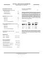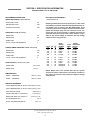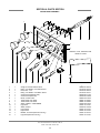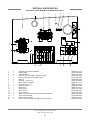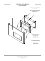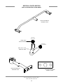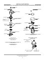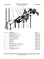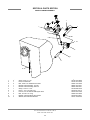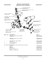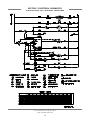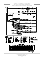
1
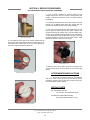
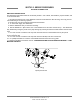
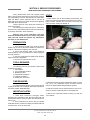
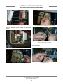
HOT WATER SANITIZING UNDERCOUNTER DISHMACHINES
TECHNICAL MANUAL
INSTALLATION MANUAL FOR EXPORT UNITS
SERVICE MANUAL FOR DOMESTIC UNITS
FOR JACKSON MODELS:
JP-24
JP-24F
JP-24B
JP-24BF
An
March 6, 2006
P/N 7610-002-49-79 (Revision D)
Company
Jackson MSC, Inc.
P.O. BOX 1060
HWY. 25E
BARBOURVILLE, KY. 40906
FAX (606) 523-9196
PHONE (606) 523-9795
www.jacksonmsc.com
REVISION
REVISION
DATE
MADE
BY
APPLICABLE
ECN
A
07-15-2002
MAW
6527
B
06-04-2003
MAW
6673, 6681
6637
Updated per ecns.
C
02-11-2004
MAW
6836
Updated per ecns.
D
03-06-2006
MAW
7421, 7231
6964, 7095
DETAILS
Release manual for service use.
Change thermostat from 05930-121-71-29 to 05930-510-03-79.
Change thermostat from 05930-121-71-36 to 05930-011-49-43.
Change Diverter Valve Assembly number from 05700-002-23-21
to 06410-012-23-21 & Diverter Valve Assembly 05700-002-23-22
to 06401-022-23-21. Replace 04820-300-07-00 vacuum breaker
with 04820-003-06-13.
i
NOMENCLATURE FOR THE MODELS COVERED IN THIS MANUAL
JP-24B
JP-24 = Undercounter, high temperature, hot water sanitizing, no booster tank.
JP-24F = Undercounter, high temperature, hot water sanitizing, no booster tank, with top and side panels.
JP-24B = Undercounter, high temperature, hot water sanitizing, with a booster tank.
JP-24BF = Undercounter, high temperature, hot water sanitizing, with a booster tank, with top and side panels.
Jackson MSC Inc. provides technical support for all
of the dishmachines detailed in this manual. We
strongly recommend that you refer to this manual
before making a call to our technical support staff.
Please have this manual with you when you call so
that our staff can refer you, if necessary, to the proper page. Technical support is available from 8:00
a.m. to 5:00 p.m. (EST), Monday through Friday.
Technical support is not available on holidays.
Contact technical support toll free at 1-888-8005672. Please remember that technical support is
available for service personnel only.
Model:
Serial No.:
Installation Date:
Service Rep. Name:
Phone No.:
ii
TABLE OF CONTENTS
SECTION
I.
DESCRIPTION
PAGE
SPECIFICATION INFORMATION
Specifications JP-24/JP-24F
Specifications JP-24B/JP-24BF
Dimensions
2
3
4
INSTALLATION/OPERATION INSTRUCTIONS
Installation Instructions
Electrical Installation Instructions
Operation Instructions
Detergent Control
Cycle Counter Retrofit Kit Instructions
6
7
8
9
10
PREVENTATIVE MAINTENANCE
Preventative Maintenance
12
IV.
TROUBLESHOOTING
14
V.
SERVICE PROCEDURES
Rinse Solenoid Valve Repair Parts Kit
Vacuum Breaker Repair Parts Kit
Replacing the Pump Motor /Booster Tank Heater
Replacing the Drain Valve
Rinse Regulating Thermostat Replacement
17
21
23
24
25
PARTS SECTION
Gauge Panel Assembly
Electrical Panel Assembly (JP-24/F 208-240 Volt, 50/60Hz)
Electrical Panel Assembly (JP-24B/BF 208-240 Volt, 50/60Hz)
Electrical Panel Assembly (JP-24B/BF 460 Volt, 60Hz)
Gauge Panel Assembly (Used with the external mounted control panel assemblies)
Electrical Panel Assembly (External & AMTRAK Option)
Kick Plate Assembly
Incoming Plumbing Assembly (JP-24/JP-24F)
Incoming Plumbing Assemblies(JP-24B/JP-24BF)
Rinse Stiffener/Rinse Hub Weldment
Solenoid Valve Repair Kit/Vacuum Breaker Repair Kit/Water Pressure Regulator Kit (WPRK Option)
Drain Valve Assembly
Drain Plumbing Assembly
Wash Motor to Wash Tub Assembly
Rinse Tank & Components/Wash Heater Kit
Door Assembly
Miscellaneous Door Sub-Assemblies
Rinse Arm & Wash Arm Assemblies
Frame, Shroud, & Panel Components/Miscellaneous Parts
Cycle Counter Retrofit Kit
30
31
32
32
34
34
37
38
39
40
41
42
43
44
45
46
47
48
49
50
SCHEMATICS
JP-24/JP-24F 208/230 V, 50/60 HZ, single phase
JP-24B/JP-24BF 208/230 V, 50/60 HZ, single phase
JP-24B/JP-24BF 460 V, 60 HZ, three phase
52
53
54
II.
III.
VI.
VII.
JP-24 Technical Manual 7610-002-49-79 Rev. D
Issued: 03-06-2006 Revised: N/A
iii
SECTION 1:
SPECIFICATION INFORMATION
1
SECTION 1: SPECIFICATION INFORMATION
SPECIFICATIONS of the JP-24/JP-24F
ELECTRICAL REQUIREMENTS
PERFORMANCE/CAPABILITIES
WASH MOTOR HP
OPERATING CAPACITY (RACKS/HOUR)
RACKS PER HOUR
30
DISHES PER HOUR
600
GLASSES PER HOUR
600
NOTE: Typical Electrical Circuit is based upon (1) 125% of the
full amperage load of the machine and (2) typical fixed-trip circuit breaker sizes as listed in the NEC 2002 Edition. Local
codes may require more stringent protection than what is displayed here. Always verify with your electrical service contractor that your circuit protection is adequate and meets all
applicable national and local codes. These numbers are provided in this manual simply for reference and may change
without notice at any given time.
OPERATING CYCLE (SECONDS)
WASH TIME
82
DRAIN TIME
28
RINSE TIME
10
TOTAL CYCLE TIME (MINUTES)
2
JP-24/JP-24F:
5 MINUTE TIMER OPERATING CYCLE (SECONDS)
WASH TIME
262
DRAIN TIME
28
RINSE TIME
10
TOTAL CYCLE TIME (MINUTES)
5
VOLTS
PH
HZ
RINSE
HEATER
RATINGS
208
230
1
1
50
50
900KW
1100KW
12
12
15 AMP
15 AMP
208
230
1
1
60
60
900KW
1100KW
10
10
15 AMP
15 AMP
(21.5) 5.65
TEMPERATURES
WASH --- (MINIMUM)
(65.6°C) 150°F
RINSE --- (MINIMUM)
(82.2°C) 180°F
WATER REQUIREMENTS
INLET TEMPERATURE
(82.2°C) 180°F
GALLONS PER HOUR
(198.7L) 52.3
WATER LINE SIZE I.P.S. (Minimum)
(1.27 cm) 1/2”
DRAIN LINE SIZE I.P.S. (Minimum)
(3.81 cm) 1 1/2”
FLOW PRESSURE P.S.I.
FLOW, GALLONS PER MINUTE
TOTAL
AMPS
TYPICAL
ELECTRICAL
CIRCUIT
NOTE: Always refer to the machine data plate for specific
electrical and water requirements. The material provided on
this page is for reference only and may be subject to change
without notice.
TANK CAPACITY (LITERS) (GALLONS)
WASH TANK
3/4
20A5
(27L) 7.1
JP-24 Technical Manual 7610-002-49-79 Rev. D
Issued: 03-06-2006 Revised: N/A
2
SECTION 1: SPECIFICATION INFORMATION
SPECIFICATIONS of the JP-24B/JP-24BF
PERFORMANCE/CAPABILITIES
ELECTRICAL REQUIREMENTS
OPERATING CAPACITY (RACKS/HOUR)
WASH MOTOR HP
RACKS PER HOUR
30
DISHES PER HOUR
600
GLASSES PER HOUR
600
NOTE: Typical Electrical Circuit is based upon (1) 125% of the
full amperage load of the machine and (2) typical fixed-trip circuit breaker sizes as listed in the NEC 2002 Edition. Local
codes may require more stringent protection than what is displayed here. Always verify with your electrical service contractor that your circuit protection is adequate and meets all
applicable national and local codes. These numbers are provided in this manual simply for reference and may change
without notice at any given time.
OPERATING CYCLE (SECONDS)
WASH TIME
82
DRAIN TIME
28
RINSE TIME
10
TOTAL CYCLE TIME (MINUTES)
2
5 MINUTE TIMER OPERATING CYCLE (SECONDS)
WASH TIME
262
DRAIN TIME
28
RINSE TIME
10
TOTAL CYCLE TIME (MINUTES)
5
TANK CAPACITY (LITERS) (GALLONS)
WASH TANK
(21.5) 5.65
RINSE TANK
(11.4) 3
(65.6°C) 150°F
RINSE --- (MINIMUM)
(82.2°C) 180°F
VOLTS
PH
HZ
RINSE
HEATER
RATINGS
208
230
208
230
220
1
1
1
1
1
50
50
50
50
50
6.7KW
8.2KW
8.2KW
10KW
9.15KW
40
43
47
51
48
50 AMP
60 AMP
60 AMP
70 AMP
60 AMP
208
230
208
230
460
460
1
1
1
1
1
1
60
60
60
60
60
60
6.7KW
8.2KW
8.2KW
10KW
480/8.2KW
480/9.6KW
39
46
42
50
11
14
50 AMP
60 AMP
60 AMP
70 AMP
15 AMP
20 AMP
WATER REQUIREMENTS
INLET TEMPERATURE (40° Booster Heater) (82.2°C) 140°F
INLET TEMPERATURE (70° Booster Heater) (43.3°C) 110°F
GALLONS PER HOUR
(198.7L) 52.3
WATER LINE SIZE I.P.S. (Minimum)
(1.27 cm) 1/2”
DRAIN LINE SIZE I.P.S. (Minimum)
FLOW PRESSURE P.S.I.
FLOW, GALLONS PER MINUTE
TOTAL
AMPS
TYPICAL
ELECTRICAL
CIRCUIT
NOTE: Always refer to the machine data plate for specific
electrical and water requirements. The material provided on
this page is for reference only and may be subject to change
without notice.
TEMPERATURES
WASH --- (MINIMUM)
3/4
(3.81 cm) 1 1/2”
20A5
(27L) 7.1
JP-24 Technical Manual 7610-002-49-79 Rev. D
Issued: 03-06-2006 Revised: N/A
3
SECTION 1: SPECIFICATION INFORMATION
JP-24 DIMENSIONS
2 1/2” (6.4 cm) Min. Wall Clearance
LEGEND
A - Water Inlet 1/2” ID Female Pipe Thread, 2 1/2”
AFF
B - Detergent Feeder Connection
C - Electrical Connection
D - Drain Connection Flexible Hose 6’ Free
Length,
1” ID x 1 3/8” OD
E - Rinse Additive Connection
E
12”
(30.5 cm)
19”
(48.3 cm)
22 5/8”
(57.5 cm)
C
16 3/4”
(42.5 cm)
DOOR OPEN
D
6 1/2”
(16.5 cm)
E
A
24 1/4”
(61.6 cm)
4 1/2”
(11.4 cm)
B
C
8 1/2”
(21.6 cm)
2 1/2”
(6.47 cm)
33 1/4”
(84.5 cm)
13 1/4”
(33.7 cm)
A
3 3/4” (9.5 cm)
2 3/4” (7 cm)
4 1/4”
(10.8 cm)
DIMENSIONS
Height (minimum):
Height (maximum):
Width:
Depth:
Wall Clearance (minimum):
33 1/4” (84.5 cm)
34 1/4” (87 cm)
24” (60.9 cm)
22 5/8” (57.5 cm)
2 1/2” (6.4 cm)
Inside Clearance Height:
Inside Clearance Width:
Inside Clearance Depth:
Door Open Depth:
*All dimensions are for reference only and are subject to change without notice.
JP-24 Technical Manual 7610-002-49-79 Rev. D
Issued: 03-06-2006 Revised: N/A
4
14 1/2” (36.8 cm)
20 1/4” (51.4 cm)
21 1/4” (54 cm)
39 1/2” (100.3 cm)
SECTION 2:
INSTALLATION/OPERATION
INSTRUCTIONS
5
SECTION 2: INSTALLATION/OPERATION INSTRUCTIONS
INSTALLATION INSTRUCTIONS
VISUAL INSPECTION: Before installing the unit, check the container and machine for damage. A damaged container is an indicator that there may be some damage to the machine. If there is damage to both the container and machine, do not throw away
the container. The dishmachine has been inspected and packed at the factory and is expected to arrive to you in new, undamaged condition. However, rough handling by carriers or others may result in there being damage to the unit while in transit. If
such a situation occurs, do not return the unit to Jackson; instead, contact the carrier and ask them to send a representative to
the site to inspect the damage to the unit and to complete an inspection report. You must contact the carrier within 48 hours of
receiving the machine. Also, contact the dealer through which you purchased the unit.
UNPACKING THE DISHMACHINE: Once the machine has been removed from the container, ensure that there are no missing parts from the machine. This may not be obvious at first. If it is discovered that an item is missing, contact Jackson immediately to have the missing item shipped to you.
LEVEL THE DISHMACHINE: The dishmachine is designed to operate while being level.
This is important to prevent any damage to the machine during operation and to ensure the
best results when washing ware. The unit comes with adjustable bullet feet, which can be
turned using a pair of channel locks or by hand if the unit can be raised safely. Ensure that
the unit is level from side to side and from front to back before making any connections.
Adjustable Bullet Foot
PLUMBING THE DISHMACHINE: All plumbing connections must comply with all applicable local, state, and national plumbing codes. The plumber is responsible for ensuring that
the incoming water line is thoroughly flushed prior to connecting it to any component of the
dishmachine. It is necessary to remove all foreign debris from the water line that may potentially get trapped in the valves or cause an obstruction. Any valves that are fouled as a result
of foreign matter left in the water line, and any expenses resulting from this fouling, are not
the responsibility of the manufacturer.
Drain Hose
CONNECTING THE DRAIN LINE: The JP-24 series machines are a pumped (pressure)
drain capable of pumping waste water to a height of 24 inches from the floor to the kitchen’s
drain system. The dishmachines are supplied with a 10 foot long hose that extends from the
rear side of the machine. There must also be an air gap between the machine drain line and
the floor sink or drain. If a grease trap is required by code, it should have a flow capacity of
12 gallons (45.6 Liters) per minute.
WATER SUPPLY CONNECTION: Ensure that you have read the section entitled “PLUMBING THE DISHMACHINE” above before proceeding. Install the water supply line (1/2” ID
pipe size minimum) to the dishmachine line y-strainer using copper pipe. It is recommended that a water shut-off valve be installed in the water line between the main supply and the
machine to allow access for service. The water supply line is to be capable of 20A5 PSI
“flow” pressure at the recommended temperature indicated on the data plate.
Back of Machine Showing Drain Hose
Do to areas where the water pressure fluctuates or is greater than the recommended pressure, it is recommended installing a water pressure regulator. Do not confuse static pressure
with flow pressure. Static pressure is the line pressure in a “no flow” condition (all valves and
services are closed). Flow pressure is the pressure in the fill line when the fill valve is
opened during the cycle.
It is also recommended that a shock absorber (not supplied) be installed in the incoming
water line. This prevents line hammer (hydraulic shock), induced by the solenoid valve as it
operates, from causing damage to the equipment.
PLUMBING CHECK: Slowly turn on the water supply to the machine after the incoming fill
line and the drain line have been installed. Check for any leaks and repair as required. All
leaks must be repaired prior to placing the machine in operation.
JP-24 Technical Manual 7610-002-49-79 Rev. D
Issued: 03-06-2006 Revised: N/A
6
Incoming Plumbing Y-Strainer
SECTION 2: INSTALLATION/OPERATION INSTRUCTIONS
ELECTRICAL INSTALLATION INSTRUCTIONS
ELECTRICAL POWER CONNECTION: Electrical and grounding connections must comply with the applicable portions of the
National Electrical Code ANSI/NFPA 70 (latest edition) and/or other electrical codes.
Disconnect electrical power supply and place a tag at the disconnect switch to indicate that you are working on the circuit.
The dishmachine data plate is located on the front of the machine. Refer to the data plate for machine operating requirements,
machine voltage, total amperage load and serial number.
Ground Lug
Terminal Block
To install the incoming power lines, remove the kick panel. This will require taking a phillips head screwdriver and removing the two screws at the bottom of
the kick panel; open the door slightly while carefully lifting the kick panel up and
out of the way. Install 3/4” conduit into the pre-punched holes in the back of the
control box. Route power wires and connect to power block and grounding lug.
Install the service wires (L1 and L2) to the appropriate terminals as they are
marked on the terminal block. Install the grounding wire into the lug provided.
It is recommended that “DE-OX” or another similar anti-oxidation agent be
used on all power connections.
VOLTAGE CHECK: Ensure that the power switch is in the OFF position and
apply power to the dishmachine. Check the incoming power at the terminal
block and ensure it corresponds to the voltage listed on the data plate. If not,
contact a qualified service agency to examine the problem. Do not run the dishmachine if the voltage is too high or too low. Shut off the service breaker and
mark it as being for the dishmachine. Advise all proper personnel of any problems and of the location of the service breaker. Replace the control box cover
and tighten down the screws.
CHEMICAL CONNECTIONS: All chemical hookup locations are located on the back of the dishmachine. Please
refer to the drawing at the right for the correct connection
point.
Control Box Electrical Connection
Brass Plug
Rinse Aid Fitting
Detergent Fitting
Back of Unit Showing Chemical Connection Points
JP-24 Technical Manual 7610-002-49-79 Rev. D
Issued: 03-06-2006 Revised: N/A
7
SECTION 2: INSTALLATION/OPERATION INSTRUCTIONS
OPERATION INSTRUCTIONS
PREPARATION: Before proceeding with the start-up of the unit, verify the following:
1. The strainer is in place and is clean.
2. That the wash and rinse arms are screwed securely into place and that their endcaps are tight. The wash and rinse
arms should rotate freely.
POWER UP: To energize the unit, turn on the power at the service breaker. The voltage should have been previously verified
as being correct. If not, the voltage will have to be verified.
FILLING THE WASH TUB:For the initial fill, close the door and depress the ON/FILL-OFF/DRAIN rocker switch in the ON position. The machine will run a partial cycle and fill to the factory preset level. Open the door and verify that the water level is
correct. Hereafter, the water level is controlled by the timer that has been preset at the factory. Verify that there are no other
leaks on the unit before proceeding any further. The wash tub must be completely filled before operating the wash pump to prevent damage to the component. Once the wash tub is filled, the unit is ready for operation.
NOTE: This applies to units with integral booster heaters. Make sure the orange wires at the heater contactor are connected properly. They have been purposely disconnected at the factory to avoid damage to the heater element when
there is no water in the booster heater.
The machine runs a complete cycle to drain and fill. If the machine is not allowed to drain, the water will build up inside the tub.
After the initial fill, the rinse water for the current cycle will become the wash water for the next cycle.
WARE PREPARATION: Proper preparation of ware will help ensure good results and less re-washes. If not done properly, ware
may not come out clean and the efficiency of the dishmachine will be reduced. It is important to remember that a dishmachine
is not a garbage disposal and that simply throwing unscraped dishes into the machine simply defeats the purpose altogether
of washing the ware. Scraps should be removed from ware prior to being loaded into a rack. Pre-rinsing and pre-soaking are
good ideas, especially for silverware and casserole dishes. Place cups and glasses upside down in racks so that they do not
hold water during the cycle. The dishmachine is meant not only to clean, but to sanitize as well, to destroy all of the bacteria
that could be harmful to human beings. In order to do this, ware must be properly prepared prior to being placed in the machine.
DAILY MACHINE PREPARATION: Refer to the section entitled “PREPARATION” at the top of this page and follow the instructions there. Afterwards, check that all of the chemical levels are correct and/or that there is plenty of detergent available for the
expected workload.
WARM-UP CYCLES: For a typical daily start-up, it is recommended to run the machine through 3 cycles to ensure that all of
the cold water is out of the system and to verify that the unit is operating correctly. To cycle the machine, ensure that the power
is on and that the tub has filled to the correct level. Open the door and the cycle light will illuminate.
When the light goes out, close the door, the unit will start, run through the cycle, and shut off automatically. Repeat this two
more times. The unit should now be ready to proceed with the washing of ware.
WASHING A RACK OF WARE: To wash a rack, open the door completely and slide the rack into the unit. Close the door and
the unit will start automatically. Once the cycle is completed, open the door and remove the rack of clean ware. Replace with
a rack of soiled ware and close the door. The process will then repeat itself.
OPERATIONAL INSPECTION: Based upon usage, the pan strainer may become clogged with soil and debris as the workday
progresses. Operators should regularly inspect the pan strainer to ensure it has not become clogged. If the strainer does, it will
reduce the washing capability of the machine. Instruct operators to clean out the pan strainer at regular intervals or as required
by work load.
SHUTDOWN AND CLEANING: At the end of the workday, close the door. Start a cycle, then place the ON/FILL - OFF/DRAIN
SWITCH to the “ OFF/DRAIN” position. The unit will automatically drain and turn off. Once the wash tub is drained, remove he
pan strainer. Remove soil and debris from the strainer and set to the side. Unscrew the wash and rinse arms from their manifolds. Remove the endcaps and flush the arms with water. Use a brush to clean out the inside of the arms. If the nozzles appear
to be clogged, use a toothpick to remove the obstruction. Wipe the inside of the unit out, removing all soil and scraps.
Reassemble the wash and rinse arms and replace them in the unit. The arms only need to be hand tight, do not use tools to
tighten them down. Reinstall the strainer and close the door.
JP-24 Technical Manual 7610-002-49-79 Rev. D
Issued: 03-06-2006 Revised: N/A
8
SECTION 2: INSTALLATION/OPERATION INSTRUCTIONS
DETERGENT CONTROL
Detergent usage and water hardness are two factors that contribute greatly to how efficiently your dishmachine will operate.
Using detergent in the proper amount can become, in time, a source of substantial savings. A qualified water treatment specialist can tell you what is needed for maximum efficiency from your detergent, but you should still know some basics so you’ll
understand what they are talking about.
First, you must understand that hard water greatly effects the performance of the dishmachine. Water hardness is the amount
of dissolved calcium and magnesium in the water supply. The more dissolved solids in the water, the greater the water hardness. Hard water works against detergent, thereby causing the amount of detergent required for washing to increase. As you
use more detergent, your costs for operating the dishmachine will increase and the results will decrease. The solids in hard
water also may build-up as a scale on wash and rinse heaters, decreasing their ability to heat water. Water temperature is
important in removing soil and sanitizing dishes. If the water cannot get hot enough, your results may not be satisfactory. This
is why Jackson recommends that if you have installed the machine in an area with hard water, that you also install some type
of water treatment equipment to help remove the dissolved solids from the water before it gets to the dishmachine.
Second, hard water may have you adding drying agents to your operating cycle to prevent spotting, when the real problem is
deposited solids on your ware. As the water evaporates off of the ware, the solids will be left behind to form the spotting and
no amount of drying agent will prevent this. Again, using treated water will undoubtedly reduce the occurrences of this problem.
Third, treated water may not be suitable for use in other areas of your operation. For instance, coffee made with soft water may
have an acid or bitter flavor. It may only be feasible to install a small treatment unit for the water going into the dishmachine
itself. Discuss this option with your qualified water treatment specialist.
Even after the water hardness problems have been solved, there still must be proper training of dishmachine operators in how
much detergent is to be used per cycle. Talk with your water treatment specialist and detergent vendor and come up with a
complete training program for operators. Using too much detergent has as detrimental effects as using too little. The proper
amount of detergent must be used for job. It is important to remember that certain menu items may require extra detergent by
their nature and personnel need to be made aware of this. Experience in using the dishmachine under a variety of conditions,
along with good training in the operation of the machine, can go a long way in ensuring your dishmachine operates as efficiently as possible.
Certain dishmachine models require that chemicals be provided for proper operation and sanitization. Some models even
require the installation of third-party chemical feeders to introduce those chemicals to the machine. Jackson does not recommend or endorse any brand name of chemicals or chemical dispensing equipment. Contact your local chemical distributor for
questions concerning these subjects.
Some dishmachines come equipped with integral solid detergent dispensers. These dispensers are designed to accommodate
detergents in a certain sized container. If you have such a unit, remember to explain this to your chemical distributor upon first
contacting them.
As explained before, water temperature is an important factor in ensuring that your dishmachine functions properly. The data
plate located on each unit details what the minimum temperatures must be for either the incoming water supply, the wash tank
and the rinse tank, depending on what model of dishmachine you have installed. These temperatures may also be followed by
temperatures that Jackson recommends to ensure the highest performance from you dishmachine. However, if the minimum
requirements are not met, the chances are your dishes will not be clean or sanitized. Remember, a dish can look clean, but it
may not be sanitized. Instruct your dishmachine operators to observe the required temperatures and to report when they fall
below the minimum allowed. A loss of temperature can indicate a much larger problem such as a failed heater or it could also
indicate that the hot water heater for your operation is not up to capacity and a larger one may need to be installed.
There are several factors to consider when installing your dishmachine to ensure that you get the best possible results from it
and that it operates at peak efficiency for many years. Discuss your concerns with your local chemical distributor and water
treatment specialist before there is a problem.
JP-24 Technical Manual 7610-002-49-79 Rev. D
Issued: 03-06-2006 Revised: N/A
9
SECTION 2: INSTALLATION/OPERATION INSTRUCTIONS
CYCLE COUNTER RETROFIT KIT INSTRUCTIONS
1. Locate the template on the front of the plastic control panel in the approximate location as shown in the diagram below.
2. Use a 3/32" diameter drill bit to drill the four mounting holes through the plastic control panel.
3. Mount the template to the front of the control panel using the screws and locknuts provided.
4. Using the template as a guide, cut the 1-3/8" x 1-1/8" cutout (the inside of the template) from the plastic control panel. Use
a Dremel tool (or similar) or drill multiple holes along the edge of the template in order to cut away the cutout.
5. Remove the template from the control panel.
6. Assemble the counter (with mounting plate) to the control panel using the four screws and locknuts provided.
7. One lead wire from the counter is connected together with the blue wires from the fill solenoid valve and the rinse/fill light
(using the existing wire nut that connects these two wires together).
8. The other lead wire from the counter is connected together with the red wires from the fill solenoid valve and the rinse/fill
light (using the existing wire nut that connects these two wires together).
9. The counter should increment each time the fill solenoid valve is turned on.
Template, Cycle Counter Mount
Cycle Counter Mount
JP-24 Technical Manual 7610-002-49-79 Rev. D
Issued: 03-06-2006 Revised: N/A
10
SECTION 3:
PREVENTATIVE MAINTENANCE
11
SECTION 3: PREVENTATIVE MAINTENANCE
PREVENTATIVE MAINTENANCE
The dishmachines covered in this manual are designed to operate with a minimum of interaction with the operator. However,
this does not mean that some items will not wear out in time. Jackson highly recommends that any maintenance and repairs
not specifically discussed in this manual should be performed by QUALIFIED SERVICE PERSONNEL ONLY. Performing maintenance on your dishmachine may void your warranty if it is still in effect.
There are many things that operators can do to prevent catastrophic damage to the dishmachine. One of the major causes of
component failure has to do with prescrapping procedures. A dishmachine is not a garbage disposal; any large pieces of material that are put into the machine shall remain in the machine until they are either broken up (after spreading out on your ware!)
or physically removed. Strainers are installed to help catch debris, but they do no good if they are clogged. Have operators regularly inspect the pan strainers to ensure (1) that they are free of soil and debris and (2) they are laying flat in the tub.
When cleaning out strainers, do NOT beat them on waste cans. The strainers are made of metal and can be forgiving; but once
severe damage is done, it is next to impossible for the strainer to work in the way it was designed to. Wipe out strainers with
a rag and rinse under a faucet if necessary. For stubborn debris, a toothpick should be able to dislodge any obstructions from
the perforations. Always ensure that strainers are placed back in the machine before operation and that they lay flat in the tub.
You may wish to also refer to the page entitled “Detergent Control” in order to learn more about how your water hardness will
effect the performance of your machine. Hard water makes dishmachines work harder and decreases efficiency.
Again, it is important to remind operators that trying to perform corrective maintenance on the dishmachine could lead to larger problems or even cause harm to the operator. If a problem is discovered; secure the dishmachine using proper shut down
procedures as listed in this manual and contact a QUALIFIED SERVICE AGENCY.
Some problems, however, may having nothing to do with the machine itself and no amount of preventative maintanence is
going to help. A common problem has to do with temperatures being too low. Verify that the water temperatures coming to your
dishmachine match the requirements listed on the machine data plate. There can be a variety of reasons why your water temperature could be too low and you should discuss it with a QUALIFIED SERVICE AGENCY to determine what can be done.
By following the operating and cleaning instructions in this manual, you should get the most efficient results from your machine.
As a reminder, here are some steps to take to ensure that you are using the dishmachine the way it was designed to work:
1. Ensure that the water temperatures match those listed on the machine data plate.
2. Ensure that all strainers are in place before operating the machine.
3. Ensure that all wash and/or rinse arms are secure in the machine before operating.
4. Ensure that drains are closed/sealed before operating.
5. Remove as much soil from dishes by hand as possible before loading into racks.
6. Do not overfill racks.
7. Ensure that glasses are placed upside down in the rack.
8. Ensure that all chemicals being injected to machine have been verified as being at the correct concentrations.
9. Clean out the machine at the end of every workday as per the instructions in the manual.
10. Always contact a QUALIFIED SERVICE AGENCY whenever a serious problem arises.
11. Follow all safety procedures, whether listed in this manual or put forth by local, state or national codes/regulations.
JP-24 Technical Manual 7610-002-49-79 Rev. D
Issued: 03-06-2006 Revised: N/A
12
SECTION 4:
TROUBLESHOOTING
13
SECTION 4: TROUBLESHOOTING SECTION
COMMON PROBLEMS
WARNING: Inspection, testing and repair of electrical equipment should be performed only by qualified service personnel.
Certain procedures in this section require electrical tests or measurements while power is applied to the machine. Exercise
extreme caution at all times. If test points are not easily accessible, disconnect power, attach test equipment and reapply
power to test. When replacing electrical parts, disconnect power at source circuit breaker.
Problem: Water overflow from bottom of door.
1.
2.
3.
4.
Clogged drain. Remove obstruction.
Machine not level. Level machine, or increase height to the front.
Excessive inlet pressure. Install pressure reducing valve, or adjust if one is present. Ensure flow is 20A5 PSI.
Detergent foaming. Reduce detergent quantity.
Problem: Wash motor doesn’t operate on manual wash.
1. Loose or broken wires. Reconnect or replace wires in motor.
2. Defective manual wash switch. Replace.
3. Defective motor starting relay. Replace.
Problem: Motor operates on manual wash but not on automatic.
1. Defective timer. Replace timer.
2. Defective circuit in manual wash switch. Replace switch.
Problem: No water comes through the rinse arms when the “ON/FILL” switch is depressed.
1.
2.
3.
4.
Water not turned on. Turn water on.
Defective solenoid valve. Replace solenoid valve.
Probes are dirty or coated. Clean probes.
Defective water level control. Replace.
Problem: Little or no water coming through the rinse assemblies.
1. Limed up rinse heads or piping. Delime rinse heads.
2. Low water pressure. Increase pipe size to machine. Adjust pressure regulator.
Problem: Rinse water runs continuously with breaker turned off.
1. Defective plunger in solenoid valve. Replace.
2. Defective diaphragm in solenoid valve. Replace diaphragm.
Problem: Rinse doesn’t operate on automatic during timed cycle (but does operate in auto/fill operation).
1. Timer defective. Replace timer.
Problem: Rinse water runs continuously with power applied to machine, but when circuit breaker to machine is turned
off, water stops.
1. Defective water level control. Replace.
2. Probes are dirty or coated. Clean probes.
Problem: Wash temperature not at required reading on thermometer.
1.
2.
3.
4.
Defective thermometer. Replace.
Defective thermostat. Adjust thermostat. Replace thermostat.
Rinse heater defective. Replace heater element.
Water level protection control device. Replace.
JP-24 Technical Manual 7610-002-49-79 Rev. D
Issued: 03-06-2006 Revised: N/A
14
SECTION 4: TROUBLESHOOTING SECTION
COMMON PROBLEMS
WARNING: Inspection, testing and repair of electrical equipment should be performed only by qualified service personnel.
Certain procedures in this section require electrical tests or measurements while power is applied to the machine. Exercise
extreme caution at all times. If test points are not easily accessible, disconnect power, attach test equipment and reapply
power to test. When replacing electrical parts, disconnect power at source circuit breaker.
Problem: Rinse water not at required temperature range.
1. Thermometer is defective. Replace.
2. Thermostat is defective. Adjust the thermostat. Replace if necessary.
Problem: Machine doesn’t drain when “OFF/DRAIN” switch is pressed.
1.
2.
3.
4.
5.
Drain solenoid clogged. Remove obstruction.
Defective “OFF/DRAIN” switch. Replace.
Defective motor or motor start relay. Replace.
Defective drain solenoid. Replace.
Defective timer. Replace.
Problem: No indication of pressure.
1. Water turned off. Turn water on.
2. 1/4” test cock ball valve is closed. Open the ball valve.
JP-24 Technical Manual 7610-002-49-79 Rev. D
Issued: 03-06-2006 Revised: N/A
15
SECTION 5:
SERVICE PROCEDURES
16
SECTION 5: SERVICE PROCEDURES
RINSE SOLENOID VALVE REPAIR PARTS KIT
These dishmachines are equipped with electrical
solenoid valves to allow for automatic fill and rinse. These
valves are designed to specific tolerances and design aspects
that must be met in order to function properly.
Jackson offers repair kits for replacing some of the
wear items associated with solenoid valves which will allow
you to save money in that replacement of these parts can take
place without removing the solenoid valve from the plumbing
assembly.
The instructions provided here are for maintenance
personnel only. Unauthorized persons should not attempt any
of the steps contained in these instructions.
STEPS
1. Remove the top screw with the 5/16” nutdriver. Remove the
screw and the data plate and set to the side.
Warning: many of the instructions and steps
within this document require the use of tools. Only authorized personnel should ever perform any maintenance
procedure on the dishmachine!
PREPARATION
1. Power must be secured to the unit at the service
breaker. Tag or lock out the service breaker to prevent accidental or unauthorized energizing of the machine.
2. Ensure that incoming water to the machine is
secured either by use of a shut-off valve or disconnecting the
incoming water line.
Removing the top screw
2. With the top screw and data plate removed, grasp the solenoid coil and gently pull up. The coil should slide up, allowing
you to remove it from the valve bonnet. If you are wanting to
replace the coil, continue on with Step 3. If you are wanting to
replace some of the internal components of the valve, proceed
to step 12.
TOOLS REQUIRED
The following tools will be needed to perform this
maintenance evolution:
1. Small flathead screwdriver
2. Medium flathead screwdriver
2. Needle nose pliers
3. 5/16” nutdriver
4. Channel locks
5. 12” pipe wrench
TIME REQUIRED
It is estimated that it will take (1) person twenty minutes to perform this task, not including all of the items indicated in the section entitled “PREPARATION”.
Removing the coil
IMPORTANT NOTES
3. NOTE: Replacing the solenoid coil requires working with
the wiring of your machine. It is important that all wiring maintenance be performed by qualified personnel. Always verify
the wiring steps presented in this instruction with the schematic that shipped with the unit. A current schematic can also be
found in the unit’s installation manual. Before beginning any
step that involves working with wiring, ensure that the steps
located in the section entitled “Preparation” have been performed. Power must be secured to the machine at the service
breaker. Failure to do so could result in severe injury to maintenance personnel.
1. Read these instructions thoroughly before attempting this maintenance evolution. Become familiar with the parts
and what actions need to be taken. This will save time in the
long run!
2. The procedures demonstrated in this manual are
shown being performed on an AJ-44C rack conveyor dishmachine. The actual maintenance steps, however, apply to any
Parker style solenoid valve found on a Jackson dishmachine.
JP-24 Technical Manual 7610-002-49-79 Rev. D
Issued: 03-06-2006 Revised: N/A
17
SECTION 5: SERVICE PROCEDURES
RINSE SOLENOID VALVE REPAIR PARTS KIT (CONTINUED)
Loosening the conduit nut
Prying open the coil wire cover
4. When replacing the coil, ensure that when removing the coil
wire cover that care is taken not to damage the wires inside.
Using the medium flathead screwdriver, gently use it to open
the cover enough to where it could be pulled off.
7. Using a pair of channel locks, gently loosen the conduit
retaining ring for the conduit nut. Once it is loosened, use your
fingers to unscrew and remove it.
8. Pull the conduit away and discard the bad coil. Take the
new coil and attach the conduit, reinstall & tighten the conduit
nut, and pull the wires through so that you will be able to wire
the valve back up.
9. Reconnect the wires from the conduit to the wires from the
solenoid as they had been connected previously. Ensure that
the wire nuts are on tight.
10. Slide the coil wire cover back on, taking care not to damage the wires.
11. If you are done performing maintenance on the valve, continue on to step 22. Otherwise, please go on to step 12.
Straightening the wires
5. Once the coil wire cover has been removed and set to the
side, take the internal wires and pull them out straight.
Loosening the valve bonnet
12. To remove the valve bonnet, grasp it with the jaws of the
pipe wrench and turn to the left. Note: on some models you
may have to remove the valve in order to perform this and any
further steps. Be careful not to damage the plumbing assembly. Only use the pipe wrench enough to where you can spin
the valve bonnet off with your hand.
Removing the wire nuts
6. Remove the wire nuts from the wires and separate them.
JP-24 Technical Manual 7610-002-49-79 Rev. D
Issued: 03-06-2006 Revised: N/A
18
SECTION 5: SERVICE PROCEDURES
RINSE SOLENOID VALVE REPAIR PARTS KIT (CONTINUED)
Removing the valve bonnet
13. Slowly remove the valve bonnet. Note: The spring for the
plunger is located directly under the bonnet and may come
free if you are not careful. Remove the plunger, spring and
valve bonnet and place to the side.
Removing the diaphragm
17. Remove the diaphragm retainer and then the diaphragm
itself. Many problems associated with a solenoid valve can be
traced to a clogged pilot port in the diaphragm.
Removing the O-ring
14. Remove the O-ring and inspect it. If it has any tears or cuts
or excessive flat spaces, it should be replaced.
Pointing out the extension hole
15. Examine the threads for the valve bonnet. Check them for
scoring or signs of damage. Take a cloth and clean them out
to remove any foreign particles that might get lodged in the
threads and cause a leak. Severely damage threads should
not be repaired; instead it is recommended that the entire
valve should be replaced. These instructions do not provide
information on replacing the solenoid valve.
16. Note: Even though an O-ring may not appear damaged, it
is a good idea to go ahead and replace it if you have a new
one. This will help ensure that your valve remains leak-free in
the future!
18. As indicated in the photo above, the extension hole can
become clogged. If it is difficult to clean out, you can use a
heated straight pin to push through the hole. The center hole,
the pilot port, must also be clear. If the diaphragm is torn or
bent in any way, it must be replaced.
1
2
Diaphragm showing (1) pilot port and (2) extension hole
JP-24 Technical Manual 7610-002-49-79 Rev. D
Issued: 03-06-2006 Revised: N/A
19
SECTION 5: SERVICE PROCEDURES
RINSE SOLENOID VALVE REPAIR PARTS KIT (CONTINUED)
21. With the mesh screen removed, look down into the valve
and verify it is not clogged. Remove any foreign objects from
the valve body that would obstruct flow.
22. Reassemble the valve, reversing the steps needed to take
it apart. Replace defective replacement parts with new parts
from ordered kits. Ensure that components are sufficiently
tightened to prevent leakage.
AFTER MAINTENANCE ACTIONS
Reconnect the incoming water (if disconnected) and
turn on. Then restore power to the unit. Run the unit for at
least 10 minutes to ensure there are no leaks. If any problems
arise please contact Jackson.
Removing the screen retainer
19. Using the small flathead screwdriver, lift out the screen
retainer. Verify that the holes in it are free of clogs and debris.
SPECIAL PARTS
Solenoid Valve Plunger Kit
Includes plunger and spring
Part number 06401-003-07-40
Solenoid Valve Diaphragm Kit
Includes diaphragm and o-ring
Part number 06401-003-07-41 (1/2” NPT)
Solenoid Valve 110 Volt Coil and Housing Kit
Part number 06401-003-07-43
Solenoid Valve 220 Volt Coil and Housing Kit
Part number 06401-003-07-44
Removing the mesh strainer screen
20. Again using the small flathead screwdriver, carefully
remove the mesh screen from inside the valve body. The
screen should be taken and rinsed out to remove any debris
fouling it.
Complete Solenoid Valve
Part number 04810-100-12-18 (1/2”, 110 Volt)
Part number 04810-100-09-18 (1/2”, 220 Volt)
View inside the solenoid valve body
JP-24 Technical Manual 7610-002-49-79 Rev. D
Issued: 03-06-2006 Revised: N/A
20
SECTION 5: SERVICE PROCEDURES
VACUUM BREAKER REPAIR PARTS KIT
These dishmachines are equipped with vacuum
breakers to serve as back-flow prevention devices. ASSE
requirements specify what type of back-flow prevention is necessary on dishmachines. Vacuum breakers, unlike air gaps,
have certain parts that have specific tolerances and design
aspects that must be met in order to function properly.
Jackson offers repair kits for replacing some of the
wear items associated with vacuum breakers which will allow
you to save money in that replacement of these parts can take
place without removing the vacuum breaker from the plumbing assembly.
The instructions provided here are for maintenance
personnel only. Unauthorized persons should not attempt any
of the steps contained in these instructions.
STEPS
1. Note: These instructions only apply to vacuum breakers
(1/2” NPT and 3/4” NPT) as pictured below. The repair kits
indicated in these instructions will only work on those style of
back-flow preventers. If you have a machine with a different
style of vacuum breaker, contact Jackson about replacement
components.
Warning: many of the instructions and steps
within this document require the use of tools. Only authorized personnel should ever perform any maintenance
procedure on the dishmachine!
PREPARATION
Vacuum breaker
1. Power must be secured to the unit at the service
breaker. Tag or lock out the service breaker to prevent accidental or unauthorized energizing of the machine.
2. Ensure that incoming water to the machine is
secured either by use of a shut-off valve or disconnecting the
incoming water line.
2. Note: Even though the photos in these instructions show a
vacuum breaker that has been removed from the plumbing
assembly, these maintenance steps could be performed with it
installed so long as the requirements in the section entitled
“PREPARATION” have been met.
3. Remove the top cap by gripping firmly and turning to the
left. The cap should come off after a few turns.
TOOLS REQUIRED
The following tools will be needed to perform this
maintenance evolution:
1. Small flathead screwdriver
2. Needle nose pliers
TIME REQUIRED
It is estimated that it will take (1) person twenty minutes to perform this task, not including all of the items indicated in the section entitled “PREPARATION”.
IMPORTANT NOTES
1. Read these instructions thoroughly before attempting this maintenance evolution. Become familiar with the parts
and what actions need to be taken. This will save time in the
long run!
Removing the cap
4. Set the cap to the side.
5. Using the needle nose pliers, gently lift out the plunger and
set to the side. Examine the brass seating surface inside the
vacuum breaker. The plunger is required to sit flat on this surface so it must be free of defects, imperfections and the like. If
there is debris, remove it. If it is chipped or cracked then the
vacuum breaker must be replaced. Failure to do so may result
in the vacuum breaker not working according to its design and
could result in damage to the dishmachine.
JP-24 Technical Manual 7610-002-49-79 Rev. D
Issued: 03-06-2006 Revised: N/A
21
SECTION 5: SERVICE PROCEDURES
VACUUM BREAKER REPAIR PARTS KIT (CONTINUED)
7. If any of these conditions are present, replace the old
plunger with the new one from your kit. Verify that the new
plunger is also free from defects. If it is not, contact Jackson
immediately.
8. The plunger should drop into the vacuum breaker and seat.
Ensure it is not flipped upside down (the orange seal ring
should be up towards the top of the vacuum breaker).
9. Pick up the cap and examine it. With a soft towel, remove
any grit, grime or debris that may have gotten caught in the
threads of both the cap retainer or the vacuum breaker body.
There is an O-ring that should be present on the cap retainer
as well. Regardless of the condition of the plunger, this O-ring
should be replaced once the cap is removed. Using a small
flathead screwdriver, remove the old O-ring.
Removing the plunger
6. Your repair kit comes with a new plunger. Examine the old
one and ensure that the mating surface is not damaged or cut.
Also inspect the rubber seal on the top of the plunger to
ensure it is in good condition and not torn.
Replacing the O-ring
10. With the new O-ring in place, screw the cap back on the
vacuum breaker body. The cap needs to only be hand tight
(snug).
Examining the seal ring on the plunger
AFTER MAINTENANCE ACTIONS
1. Reconnect the incoming water (if disconnected)
and turn on. Then restore power to the unit. Run the unit for
at least 10 minutes to ensure there are no leaks. If any problems arise please contact Jackson.
SPECIAL PARTS
Vacuum breaker repair kit:
For 1/2” NPT order 06401-003-06-23
Complete Vacuum Breaker Assembly
Part number 04820-003-06-13 (1/2”)
Examining the plunger seating surface
JP-24 Technical Manual 7610-002-49-79 Rev. D
Issued: 03-06-2006 Revised: N/A
22
SECTION 5: SERVICE PROCEDURES
REPLACING THE PUMP MOTOR/REPLACING THE HEATER
REPLACING THE PUMP MOTOR
The following list of tools will be needed to complete this procedure. 5/6” nutdriver, phillips screwdriver, 7/16” socket
and ratchet, and 7/16” wrench.
1. Disconnect the electrical power to the dishwasher at the main circuit breaker box when servicing. Place a tag on the circuit box indicating the circuit is being repaired.
2. Disconnect power and conduit from dishmachine terminal block.
3. Turn off the water supply and disconnect the water supply line.
4. Disconnect the dishmachine drain hose from the kitchen’s
drain. Drain the machine of any water at this time.
5. Move the machine out and lay machine onto its back.
6. Use a 5/16” nutdriver to loosen the hose clamp and remove
the pump hose to the drain valve.
8
7. Use a 5/16” nutdriver to loosen the hose clamp and remove
6
the pump hose from the suction casting.
8. Use a 5/16” nutdriver to loosen the hose clamp and remove
the pump hose from the discharge hub casting.
9. Use a 7/16” socket and ratchet, and a 7/16” wrench to
remove the drain valve mounting bracket from the motor bracket.
10. Use a 7/16” socket and ratchet to remove the pump motor
assembly by loosening the (4) locknuts securing the motor
mounting bracket. NOTE: The motor mounting bracket is slot10
9
ted to allow for easy removal and installation. Remove (2) of the
7
locknuts on one side and slide the assembly toward that side
and remove. Once the assembly is removed, disconnect the
wire leads from the motor wiring box.
11. Install replacement motor in reverse order of above.
Replacing the Pump Motor
REPLACING THE BOOSTER TANK HEATER
The following list of tools will be needed to complete this procedure: phillips screwdriver and 1/2” socket and ratchet.
1. Disconnect the electrical power to the dishwasher at the main circuit breaker box when servicing. Place a tag on the circuit box indicating the circuit is being repaired.
2. Use the phillips screwdriver to remove the two screws from the bottom of the kick panel.
3. Disconnect power and conduit from dishmachine terminal block.
4. Turn off the water supply to the dishmachine.
5. VERY IMPORTANT: Disconnect wire lead (orange/white) from heater contactor coil. Note: Wire is tagged in electrical
panel.
6. Drain water from booster tank.
7. Remove the wires from the heater.
Heater Gasket
8. Use a 1/2” socket and ratchet to remove the (4) 5/16-18 hex
nuts and lock washers. Remove the heater and heater gasket
from booster tank.
Heater
8. Install the replacement heater and gasket, the tighten firmly.
9. Connect wire leads to heater and tighten firmly.
10. Turn on water supply and power to dishmachine.
11. Place cycle switch in AUTO position and depress power
switch to ON/FILL position.
12. VERY IMPORTANT: Run the dishmachine through several
complete cycles and check water level in wash sump. If there is
water in the wash sump, reconnect the wire lead (orange/white)
previously removed from the heater contactor coil.
Hex Nuts & Washers
13. Run the dishwasher through several cycles and check to see
that rinse and wash temperatures are correct.
Replacing the Heater
JP-24 Technical Manual 7610-002-49-79 Rev. D
Issued: 03-06-2006 Revised: N/A
23
SECTION 5: SERVICE PROCEDURES
REPLACING THE DRAIN VALVE
REPLACING THE DRAIN VALVE
The following list of tools will be needed to complete this procedure. 5/16” nutdriver, flat screwdriver, phillips screwdriver, and
7/16” socket and ratchet.
1. Disconnect the electrical power to the dishwasher at the main circuit breaker box when servicing. Place a tag on the circuit box indicating the circuit is being repaired.
2. Disconnect the power and conduit from dishmachine terminal block.
3. Turn off the water supply to the dishmachine.
4. Move the dishmachine away from the wall for servicing.
5. Use a 7/16” socket and ratchet to remove the lower enclosure panel at rear of machine.
6. Drain the dishmachine. Siphon out the water or remove inlet hose to drain valve and drain into pan. The dishmachine
may be drained by opening the petcock on the pump housing or by removing the wash thermometer bulb from the lower wash
tank.
7. Use a 5/16” nutdriver to loosen the hose clamp and remove the inlet hose to the drain valve from the pump motor.
8. Use a phillips screwdriver to remove the cover from the valve. Use a flat screwdriver to disconnect the lead wires and
ground to the drain valve.
9. Use a 5/16” nutdriver to loosen the hose clamp and remove the discharge hose from the drain valve.
10. Use a phillips screwdriver to remove the screws attaching the drain valve to the mounting plate.
11. Reverse the procedures to install the new valve. INSURE GROUND WIRE LEAD IS CONNECTED PROPERLY TO TERMINAL ON THE MOTOR.
7
8
10
9
Replacing the Drain Valve
JP-24 Technical Manual 7610-002-49-79 Rev. D
Issued: 03-06-2006 Revised: N/A
24
SECTION 5: SERVICE PROCEDURES
RINSE REGULATING THERMOSTAT REPLACEMENT
Many dishmachines comes with integral booster
tanks to ensure proper temperature of the final rinse. Jackson
has predominantly used two manufacturers of thermostats,
EGO and Stemco. These instructions are for use with kit
06401-003-13-94, which is to replace an EGO rinse regulating
thermostat with a Stemco brand.
Jackson offers all of the repair parts necessary for
performing this task.
The instructions provided here are for maintenance
personnel only. Unauthorized persons should not attempt any
of the steps contained in these instructions.
STEPS
1. Some models, such as the Tempstar pictured below, will
require that the thermostat bracket removed from the heater.
Using a ratchet, extension and 1/2” socket, remove the nuts
and lock washer holding the bracket on.
Warning: many of the instructions and steps
within this document require the use of tools. Only authorized personnel should ever perform any maintenance
procedure on the dishmachine!
PREPARATION
1. Power must be secured to the unit at the service
breaker. Tag or lock out the service breaker to prevent accidental or unauthorized energizing of the machine.
2. Ensure that incoming water to the machine is
secured either by use of a shut-off valve or disconnecting the
incoming water line.
3. The unit must be drained completely with the drain
stopper removed (if applicable).
4. Remove any and all access covers.
Removing the thermostat bracket/heater nuts.
TOOLS REQUIRED
The following tools may be needed to perform this
maintenance evolution:
1. 3/8” Nutdriver
2. 7/16” Combination Wrench
3. Needlenose Pliers
4. Phillipshead Screwdriver
5. Flathead Screwdriver
6. Ratchet with 1/2” Socket
Removing the thermostat bracket.
TIME REQUIRED
2. With the thermostat and thermostat bracket safely out of the
way, use a 7/16” combination wrench to loosen and then
remove the imperial brass fitting holding the probe in.
It is estimated that it will take (1) person sixty minutes
to perform this task, not including all of the items indicated in
the section entitled “PREPARATION”.
3. Remove the wires from the old thermostat. It may be necessary to use the needlenose pliers to accomplish this.
IMPORTANT NOTES
4. Remove the thermostat bracket mounting nuts with the
7/16” nutdriver.
1. Read these instructions thoroughly before
attempting this maintenance task. Become familiar with the
parts and what actions need to be taken. This will save time in
the long run!
2. These instructions are shown using a Tempstar
model dishmachine. However the steps provided should work
for models such as the JP-24 as well.
JP-24 Technical Manual 7610-002-49-79 Rev. D
Issued: 03-06-2006 Revised: N/A
25
SECTION 5: SERVICE PROCEDURES
RINSE REGULATING THERMOSTAT REPLACEMENT
Location of the thermostat bracket (JP-24).
Pulling the thermostat probe and fitting from the well (Tempstar).
Remove the thermostat bracket mounting nuts with the 3/8”
nutdriver.
Removing the wires from the thermostat.
5. Attach the jumper wires to the wires that you removed from
the old thermostat.
Location of the imperial brass fitting (JP-24).
Attaching the jumper wires.
Removing the imperial brass fitting (Tempstar).
JP-24 Technical Manual 7610-002-49-79 Rev. D
Issued: 03-06-2006 Revised: N/A
26
SECTION 5: SERVICE PROCEDURES
RINSE REGULATING THERMOSTAT REPLACEMENT
9. Note: regardless of the unit this is being done to, the concept is to ensure that the thermostat cannot come into contact
with the heater leads or interfere with the placement of any
covers.
Sliding imperial fitting onto new thermostat.
6. Slide the new imperial brass fitting from your kit onto the
new thermostat.
What the installed thermostat should look like (Tempstar).
Putting the new thermostat in the well (Tempstar).
7. Insert the new thermostat/brass fitting combination into the
well and tighten down the brass fitting by hand.
What the installed thermostat should look like (JP-24B).
Removing the thermostat screws.
Tightening the brass fitting (Tempstar).
10. Use the phillipshead screwdriver to remove the attachment screws on the thermostat for the NORMALLY CLOSED
and COMMON points.
8. Use the 7/16” combination wrench to tighten down the
brass fitting, while also positioning the new thermostat so that
it does not hang over the heater.
JP-24 Technical Manual 7610-002-49-79 Rev. D
Issued: 03-06-2006 Revised: N/A
27
SECTION 5: SERVICE PROCEDURES
RINSE REGULATING THERMOSTAT REPLACEMENT
need to be run on the unit while observing the final rinse temperature. The thermostat needs to cycle so that the final rinse
water meets the indicated minimums on the machine data
plate for every cycle.
Fitting the jumper into the mounting cup.
11. Attach the ring ends of the jumpers to the cups/screws
removed from the thermostat and attach them. The white
jumper is to be connected to COMMON. The orange and
white jumper is to be connected to NORMALLY CLOSED.
Refer to your machine schematic if you have any questions
regarding this.
Calibrating the new thermostat.
SPECIAL NOTES
Work performed on Jackson dishmachines by unauthorized or unqualified personnel may void the warranty.
Before beginning this or any other maintenance evolution on
a unit under warranty, you should contact a certified Jackson
technician or Jackson Technical Service. You can find a list of
qualified service agencies in the back of you unit’s installation
manual.
SPECIAL PARTS
Thermostat Replacement Kit: 06401-003-13-94*
Securing jumpers to the thermostat.
*The kit contains a thermostat, imperial brass fitting,
jumper wires and instructions.
12. Once both wires are attached, ensure that there is no
excess hanging out where it could become pinched by any
cover or such.
13. Replace the heater nuts (if removed) and torque down as
required per the technical manual. Different models may have
different torque specifications. Contact Jackson Technical
Service if there are any questions regarding this.
AFTER MAINTENANCE ACTIONS
Once the new thermostat is installed, it will be necesary to ensure that it operates at the required and appropriate
ranges. The new thermostat has an adjustment that can be
turned using a small flathead screwdriver. Several cycles will
JP-24 Technical Manual 7610-002-49-79 Rev. D
Issued: 03-06-2006 Revised: N/A
28
SECTION 6:
PARTS SECTION
29
SECTION 6: PARTS SECTION
GAUGE PANEL ASSEMBLY
1
2
3
4
5
6
Dielectric Cover, Electrical Panel
05700-011-40-48
7
15
8
9
10
11
12
13
14
ITEM
QTY
DESCRIPTION
Mfg. No.
1
2
3
4
5
5
6
7
8
9
10
11
12
13
14
15
1
1
1
1
1
1
1
1
1
1
1
1
1
1
1
1
Gauge, 0-100 PSI w/Green Zone
Fitting, 1/4” BARB x 1/4” FNPT Swivel
Hose, 5/16” x 12"
Fitting, 1/4” BARB x 1/4” MNPT Swivel
Control Panel (208-240 Volt)
Control Panel (460 Volt)
Decal, Control Panel
Thermometer, 96” Wash
Thermometer, 48” Rinse
Switch, ON/FILL & OFF/DRAIN
Light, Red
Switch, Delime
Light, Amber
Light, Green
Breaker, 2A Circuit (460 Volt unit only)
Light, Red (460 Volt unit only)
06680-011-86-42
04730-011-95-42
05700-011-86-45
04730-011-95-41
09330-041-41-94
09330-041-85-00
09905-031-40-55
06685-111-68-49
06685-111-68-48
05930-301-49-55
05945-111-44-45
05930-011-49-00
05945-111-44-44
05945-111-44-43
05925-111-64-18
05945-111-44-45
JP-24 Technical Manual 7610-002-49-79 Rev. D
Issued: 03-06-2006 Revised: N/A
30
SECTION 6: PARTS SECTION
ELECTRICAL PANEL ASSEMBLY (JP-24/F 208-240 VOLT)
1
2
3
4
5
6
4
7
8
9
10
11
12
13,
14, 12
4
15
16
ITEM
QTY
DESCRIPTION
Mfg. No.
1
2
3
4
5
6
7
8
9
10
11
12
13
14
14
14
15
16
17
1
1
1
8
1
1
1
1
1
1
1
4
1
1
1
1
1
2
4
Electrical Control Panel Weldment
Bushing, Snap
Contactor, Motor
Screw, 10-32 x 3/8” Phillips Truss Round Head
Locknut, 10-24 S/S Hex with Nylon Insert
Wire Lug
Grommet, 1 1/8" Heyco
Decal, Copper Conductors
Decal, Ground, L1, L2
Bracket, Relay Mounting
Relay, 220-240 Volt
Screw, 6-32 x 3/8” Sems with External Tooth Lockwasher
Decal, Timer
Timer, 60 HZ
Timer, 50 HZ
Timer, 5 Minute
Track, Terminal 3 5/16"
Block, Snap-in Terminal
Locknut, 1/4”-20 S/S Hex with Nylon Insert (not shown)
05700-011-41-79
05975-210-03-00
05945-002-74-20
05305-173-12-00
05310-373-01-00
05940-200-76-00
05975-210-08-00
09905-011-47-35
09905-101-40-82
05700-002-37-85
05945-111-89-75
05305-002-25-91
09905-011-40-70
05945-121-41-60
05945-002-13-34
05945-121-44-89
05700-000-43-60
05940-500-02-19
05310-374-01-00
JP-24 Technical Manual 7610-002-49-79 Rev. D
Issued: 03-06-2006 Revised: N/A
31
SECTION 6: PARTS SECTION
ELECTRICAL PANEL ASSEMBLY (JP-24B/BF 208-240 VOLT)
1
2
3
4
5
6
4
7
8
9
10
4
11
12, 13
4
14
15
ITEM
QTY
DESCRIPTION
Mfg. No.
1
2
3
4
5
6
7
8
9
10
11
12
12
12
13
14
15
16
1
1
1
9
1
1
1
1
1
1
1
1
1
1
2
1
2
4
Electrical Control Panel Weldment
Bushing, Snap
Contactor, Motor
Screw, 10-32 x 3/8” Phillips Truss Round Head
Locknut, 10-24 S/S Hex with Nylon Insert
Wire Lug
Grommet, 1 1/8" Heyco
Decal, Copper Conductors
Decal, Ground, L1, L2
Contactor, Heater
Decal, Timer
Timer, 60 HZ
Timer, 50 HZ
Timer, 5 Minute
Screw, 6-32 x 3/8” Sems with External Tooth Lockwasher
Track, Terminal 3 5/16"
Block, Snap-in Terminal
Locknut, 1/4”-20 S/S Hex with Nylon Insert (not shown)
05700-011-41-79
05975-210-03-00
05945-002-74-20
05305-173-12-00
05310-373-01-00
05940-200-76-00
05975-210-08-00
09905-011-47-35
09905-101-40-82
05945-002-74-20
09905-011-40-70
05945-121-41-60
05945-002-13-34
05945-121-44-89
05305-002-25-91
05700-000-43-60
05940-500-02-19
05310-374-01-00
JP-24 Technical Manual 7610-002-49-79 Rev. D
Issued: 03-06-2006 Revised: N/A
32
SECTION 6: PARTS SECTION
ELECTRICAL PANEL ASSEMBLY (JP-24B/BF 460 VOLT)
1
2
3
4
3
5
6
7, 8
9
10
13
11, 12,
5
14, 5
15, 16
17
18, 19, 16
ITEM
QTY
DESCRIPTION
Mfg. No.
1
2
3
4
5
6
7
8
9
10
11
12
13
14
15
16
17
18
19
20
1
1
2
2
9
1
1
3
1
1
1
1
1
1
1
2
1
1
1
4
Bushing, Snap
Track, Terminal 6 7/8"
End Clamp
Contactor, Mini
Screw, 10-32 x 3/8” Phillips Truss Round Head
Track, Terminal 3 3/4"
Decal, L1, L2, L3
Block, Snap-in Terminal
Electrical Control Panel Weldment
Grommet, 1 1/8" Heyco
Wire Lug
Ground Decal
Overload, Contactor
ACME Transformer, 480 to 120 Volt
Terminal Board, 1/4 QC
Screw, 6-32 x 3/8” Sems with External Tooth Lockwasher
Locknut, 10-24 S/S Hex with Nylon Insert
Timer, 6 Cam
Decal, Timer
Locknut, 1/4”-20 S/S Hex with Nylon Insert (not shown)
05975-210-03-00
05700-021-62-91
05940-111-60-30
05945-111-60-07
05305-173-12-00
05700-011-62-89
09905-101-12-66
05940-500-02-19
05700-031-62-94
05975-210-08-00
05940-200-76-00
09905-011-41-82
05945-111-60-08
05950-011-50-70
05940-021-94-85
05305-002-25-91
05310-373-01-00
05945-121-44-69
09905-011-40-70
05310-374-01-00
JP-24 Technical Manual 7610-002-49-79 Rev. D
Issued: 03-06-2006 Revised: N/A
33
SECTION 6: PARTS SECTION
GAUGE PANEL ASSEMBLY
This panel is used with the following:
External Control Box Option
AMTRAK External Control Box Option
1
2
3
4
5
6
7
8
Dielectric Cover, Electrical Panel
05700-011-40-48
ITEM
QTY
DESCRIPTION
Mfg. No.
1
2
3
4
5
6
7
8
1
1
1
1
1
1
1
1
Gauge, 0-100 PSI with Green Zone
Thermometer, 96” Wash
Thermometer, 48” Rinse
Control Panel, Remote JP-24
Decal, JP-24 External Control Panel
Fitting, 1/4” BARB x 1/4” FNPT Swivel
Hose, 5/16” x 12"
Fitting, 1/4” BARB x 1/4” MNPT Swivel
06680-011-86-42
06685-111-68-49
06685-111-68-48
09330-041-73-91
09905-031-73-94
04730-011-95-42
05700-011-86-45
04730-011-95-41
JP-24 Technical Manual 7610-002-49-79 Rev. D
Issued: 03-06-2006 Revised: N/A
34
SECTION 6: PARTS SECTION
ELECTRICAL PANEL ASSEMBLY (EXTERNAL OPTION & AMTRAK OPTION)
INSIDE VIEW of AMTRAK & EXTERNAL OPTIONS
FRONT VIEW EXTERNAL OPTION
1
2
3
4
6
7
8
9
10
7
11
12, 7
13
14
15
16
17
7
18
20
7
19
7
5
RIGHT SIDE VIEW AMTRAK OPTION
1
2
3
4
Electrical Component Mounting Bracket
05700-031-84-85
14
15
16
Control Box Mounting Panel
(Amtrack Option Only)
05700-001-99-38
JP-24 Technical Manual 7610-002-49-79 Rev. D
Issued: 03-06-2006 Revised: N/A
35
SECTION 6: PARTS SECTION
ELECTRICAL PANEL ASSEMBLY (EXTERNAL OPTION & AMTRAK OPTION) (CONTINUED)
ITEM
QTY
DESCRIPTION
Mfg. No.
1
1
2
2
3
4
5
6
7
8
9
10
11
12
13
14
15
16
17
18
1
1
1
1
1
1
1
1
9
1
2
1
1
1
1
1
1
1
1
1
1
1
1
2
Control Box, JP-24 External Machined
Control Box, Amtrak 24 Remote
Decal, External Control Box
Decal, Amtrak Control Box
Switch, ON/FILL & OFF/DRAIN
Switch, Delime
Contactor, Motor
Panel, Inner Control Box
Screw, 10-32 x 3/8” Phillips Truss Round Head
Track, Terminal 3 5/16"
Block, Snap-in Terminal
Decal, Ground, L1, L2
Decal, Ground
Wire Lug
Decal, Copper Conductors
Light, Red
Light, Amber
Light, Green
Decal, Timer
Timer, 60 HZ
Timer, 50 HZ
Timer, 5 Minute
Contactor, Heater
Screw, 6-32 x 3/8” Phillips Round Head
05700-031-73-01
05700-031-93-17
09905-031-84-87
09905-031-84-87
05930-301-49-55
05930-011-49-00
05945-002-74-20
05700-031-91-51
05305-173-12-00
05700-000-43-60
05940-500-02-19
09905-101-40-82
09905-011-86-86
05940-200-76-00
09905-011-47-35
05945-111-44-45
05945-111-44-44
05945-111-44-43
09905-011-40-70
05945-121-41-60
05945-002-13-34
05945-121-44-89
05945-002-74-20
05305-171-02-00
19
20
JP-24 Technical Manual 7610-002-49-79 Rev. D
Issued: 03-06-2006 Revised: N/A
36
SECTION 6: PARTS SECTION
KICK PLATE ASSEMBLY
Dielectric Cover, Kickplate Panel
05700-011-40-49
Decal, Power Disconnect Warning
09905-021-47-07
Nut, Nylon Wing, 1/4”-20
05310-994-01-00
Kickplate Weldment
05700-041-86-40
Control Panel Assembly
05700-011-40-93
Control Panel Only
09330-041-41-94
460 Control Panel Assembly
05700-002-18-38
460 Control Panel Only
09330-041-85-00
JP-24 Technical Manual 7610-002-49-79 Rev. D
Issued: 03-06-2006 Revised: N/A
37
SECTION 6: PARTS SECTION
INCOMING PLUMBING ASSEMBLY (JP-24/JP-24F)
Vacuum Breaker Assembly
Plug, 1/4” Brass
3 per machine
4730-209-01-00
Vacuum Breaker
04820-003-06-13
12
Injector Weldment
05700-031-41-83
Connects to
Rinse Injector
Clamp, Hose
04730-719-06-09
5
6
Connects to
Rinse Stiffener
8
Hose, 3/4” x 8 1/2”
05700-011-38-83
11
4
8
1
2
3
2
2
9
7
10
8
ITEM
QTY
DESCRIPTION
Mfg. No.
1
2
3
4
5
6
7
8
9
10
11
12
1
3
1
1
1
1
1
3
1
1
1
1
Y-Strainer, 1/2"
Adapter, 1/2" Ftg. x Male
Tee, 1/2” C x 1/2” C x 1/4” Female
Ball Valve, Test Cock 1/4"
Valve, Solenoid 1/2", 115 volt
Union, 1/2" C to C
Copper Tube, 1/2" x 2"
Elbow, 1/2", 90° C to C
Copper Tube, 1/2" x 19 1/2"
Copper Tube, 1/2" x 4 1/2"
Copper Tube, 1/2" x 25 1/2"
Adapter, 1/2" Ftg. x Male
04730-217-01-10
04730-011-59-53
04730-411-25-01
04810-011-72-67
04810-100-12-18
04730-412-05-01
05700-001-04-66
04730-406-01-01
05700-011-59-84
05700-011-59-83
05700-011-59-85
04730-401-03-01
JP-24 Technical Manual 7610-002-49-79 Rev. D
Issued: 03-06-2006 Revised: N/A
38
SECTION 6: PARTS SECTION
INCOMING PLUMBING ASSEMBLIES (JP-24B/JP-24BF)
Plug, 1/4” Brass
3 per machine
04730-209-01-00
Vacuum Breaker
04820-003-06-13
Injector Weldment
05700-031-41-83
Pipe Clamp
05700-011-38-62
Secured with:
Locknut, 1/4”-20 S/S
Hex with Nylon Insert
05310-374-01-00
Pipe, Assembly
1/2” NPT x 23 1/2”
05700-031-41-83
6
7
Elbow, 1/2” NPT 90° Brass
04730-011-42-96
Nipple, 1/2” Close Brass
04730-207-15-00
4
2
5
2
3
2
8
7
1
9
ITEM
QTY
DESCRIPTION
Mfg. No.
1
2
3
4
5
6
7
8
9
1
3
1
1
1
1
2
1
1
Y-Strainer, 1/2"
Adapter, 1/2" Ftg. x Male
Tee, 1/2 x 1/2 x 1/4
Ball Valve, Test Cock 1/4"
Valve, Solenoid 1/2" 220 volt
Union, 1/2" C to C
Elbow, 1/2" C to Ftg.
Copper Tube, 1/2" x 18 1/2"
Elbow, 1/2", 90° C to MSPS
04730-217-01-10
04730-011-59-53
04730-411-25-01
04810-011-72-67
04810-100-09-18
04730-412-05-01
04730-406-31-01
05700-011-44-34
04730-406-32-01
JP-24 Technical Manual 7610-002-49-79 Rev. D
Issued: 03-06-2006 Revised: N/A
39
SECTION 6: PARTS SECTION
RINSE STIFFENER/RINSE HUB WELDMENT
Rinse Tube Stiffener
05700-011-44-32
Connects to
Rinse Injector
Clamp, Hose
04730-719-06-09
Connects to
Rinse Stiffener
Hose, 3/4” x 8 1/2”
05700-011-38-83
Rinse Hub Weldment
05700-021-38-31
Vellumoid Rinse Gasket
05330-111-42-81
JP-24 Technical Manual 7610-002-49-79 Rev. D
Issued: 03-06-2006 Revised: N/A
40
SECTION 6: PARTS SECTION
RINSE SOLENOID VALVE & VACUUM BREAKER REPAIR PARTS KITS/WATER PRESSURE REGULATOR KIT OPTION
Screw
Data Plate
Cap Screw
Coil & Housing
Data Plate
Valve Bonnet
Spring position is moved
for clarity.
Goes below the plunger.
Diaphragm
Retainer
Spring & Plunger Kit
06401-003-07-40
Cap
Cap Retainer
O-Ring & Diaphragm
06401-003-07-41
O-Ring
Plunger
Components of
Repair Kit
06401-003-06-23
Screen
Retainer
Body
Mesh Screen
Valve Body
Complete Vacuum Breaker Assembly, 1/2” NPT
04820-003-06-13
Complete 110 Volt Solenoid Valve Assembly, 1/2”
04810-100-12-18
Complete WPRK Assembly
05700-002-64-67
Coil & Housing only, 1/2”
06401-003-07-43
Water Hammer Arrestor,
1/2" NPT
06685-100-05-00
Complete 220 Volt Solenoid Valve Assembly, 1/2”
04810-100-09-18
Coil & Housing only, 1/2”
06401-003-07-44
Tee, 1/2” x 1/2” x 1/2”
04730-211-27-00
JP-24 Technical Manual 7610-002-49-79 Rev. D
Issued: 03-06-2006 Revised: N/A
41
Close Nipple, 1/2”
04730-207-15-00
SECTION 6: PARTS SECTION
DRAIN VALVE ASSEMBLY
17
15
13
18
11
10
5
16
4
3
1
3
6
12
8
7
9
14
ITEM
QTY
DESCRIPTION
Mfg. No.
1
2
3
4
5
6
7
8
9
10
11
12
12
13
14
15
16
17
18
1
1
1
1
1
1
4
1
1
1
1
1
2
1
1
1
4
1
4
1
4
Diverter Valve Assembly, 115 Volt
Diverter Valve Assembly, 220 Volt
Valve, With Brackets
Hosebarb, 1” x 3/4” NPT Polypropylene
Hosebarb, 90° 1” x 3/4” NPT
Plate, Motor Mounting Weldment
Tricnut, 10-32 AK Fastener, S/S
Lockwasher, #10 External Tooth
Grommet, Heyco
Cam Weldment
Plate, Dielectric
Switch, Micro
Screw, 4-40 x 5/8"
Motor, Chemical Feeder Pump 14 RPM 115 Volt
Motor, Chemical Feeder Pump 14 RPM 220 Volt
Terminal, Ground Spade
Locknut, 10-32 S/S Hex with Nylon Insert
FW-Valve, Cover
Screw, 10-32 x 3/8” Truss Head
Decal, Warning-Disconnect Power
Screw, Mounting
06401-012-23-21
06401-022-23-21
05700-002-23-28
04730-011-65-86
04730-011-65-87
05700-031-96-02
05340-111-58-10
05311-273-02-00
05975-210-03-00
05700-011-65-78
05700-011-65-80
05930-011-65-81
05305-011-49-70
04320-111-35-13
04320-011-79-34
05940-011-75-70
05310-373-02-00
05700-031-65-70
05305-173-12-00
09905-100-75-93
05305-011-93-30
JP-24 Technical Manual 7610-002-49-79 Rev. D
Issued: 03-06-2006 Revised: N/A
42
SECTION 6: PARTS SECTION
DRAIN PLUMBING ASSEMBLY
1
2
7
8
1
9
3, 10
4
5
6
6
ITEM
QTY
DESCRIPTION
Mfg. No.
1
2
3
4
4
5
6
7
8
9
10
3
1
2
1
1
1
1
2
2
1
2
Clamp, 3/16” to 1 1/2”
Hose, Formed Drain
Bolt, 10-32 x 1/2” Slotted Truss Head
Diverter Valve Assembly, 115 Volt
Diverter Valve Assembly, 220 Volt
Clamp, 11/16” to 1 1/4”
Hose, 1” I.D. x 10 Feet Long
Locknut, 1/4”-20 S/S Hex with Nylon Insert
Bolt, 1/4”-20 x 1/2” Long
Bracket, Valve Mounting with Tricnuts
Washer, #10 External Tooth Star
04730-719-06-09
04720-121-40-36
05305-173-04-00
06401-012-23-21
06401-022-23-21
04730-002-18-40
05700-011-39-72
05310-374-01-00
05305-274-02-00
05700-021-66-37
05311-273-02-00
JP-24 Technical Manual 7610-002-49-79 Rev. D
Issued: 03-06-2006 Revised: N/A
43
SECTION 6: PARTS SECTION
WASH MOTOR TO WASH TUB ASSEMBLY
Hub, Discharge Machined
05700-021-37-90
Gasket, 2” O.D. x 1 1/2” I.D. x 1/16”
05330-200-23-00
Nut, Jam 1 1/2”-12 NPT
05700-000-86-23
Hose Clamp, 1 5/16" - 2 1/4" #28
4 per assembly
04730-719-01-37
Hose,1 1/4” x 2 1/4” Reinforced
05700-011-44-48
Gasket, Suction Adapter
05330-021-40-87
2
1 See Chart Below
3
Casting, Suction Adapter
09515-031-39-86
Locknut, 1/4”-20 S/S
05310-374-01-00
Washer, 1/4” I.D. x 3/4” O.D. S/S
05311-011-76-30
Hose, Bottom
Manifold Pump
05700-001-22-92
Washer, S/S 1/4”-20 I.D.
05311-174-01-00
Locknut, 1/4”-20 S/S
05310-374-01-00
ITEM
QTY
DESCRIPTION
Mfg. No.
1
1
Motor, Wash, 115/230 V, 60 HZ, Complete
Motor, Only
06105-131-50-93
06105-021-44-03
1
1
Motor, Wash, 115/230 V, 50 HZ, Complete
Motor, Only
06105-002-14-93
06105-003-19-78
1
1
2
3
1
1
Motor, Wash, 460 V, 60 HZ, Complete
Motor, Only
Pump Mounting Bracket
Pump Casing, Iron
06105-121-60-06
06105-002-64-03
05700-002-42-85
05930-021-44-07
The following items are not shown and are the same for each motor assembly.
Iron Adapter
Impeller
Drain Cock
Mechanical Seal
Gasket, 4.75” x 4.09” x 1/16”
Gasket, 4.75” x 4.09” x 1/64”
JP-24 Technical Manual 7610-002-49-79 Rev. D
Issued: 03-06-2006 Revised: N/A
44
04730-002-42-84
04320-021-44-02
04730-002-43-21
05330-011-44-06
05330-111-59-90
05330-002-42-86
SECTION 6: PARTS SECTION
RINSE TANK & COMPONENTS/STRIP HEATER KIT
Rinse Tank Weldment
05700-031-38-09
JP-24B/BFRINSE TANK
Fitting, 1/4” Imperial Brass
05310-924-02-05
Dielectric Cover
(Not Shown)
05700-011-40-50
Thermostat, Rinse Tank
05930-510-03-79
Kit, Rinse Thermostat Replacement
(Includes: thermostat, brass fitting,
2 jumper wires & instructions)
06401-011-66-55
Locknut, 1/4”-20 S/S
Hex with Nylon Insert
05310-374-01-00
Gasket, Heater
05330-011-47-79
Nut, 5/16”-18 S/S Hex
05310-275-01-00
Thermostat, High Limit (460 Volt Unit only)
05930-011-49-43
Lockwasher, 5/16” Split
05311-275-01-00
High Limit Thermostat Mounting Bracket
05700-011-81-64
The JPX-300H/HC/HN models covered in this manual come supplied with various heaters, depending on the characteristics
of the machine. To ensure that you order the correct heater for the model you are servicing, please refer to the following table:
40°F Rise
70°F Rise
Model
Volts
Hz
Phase
Rinse Heater (8.2 KW)
Rinse Heater (10 KW)
JPX-300H
JPX-300H
208
230
50
50
1
1
04540-111-43-21
04540-111-43-21
04540-021-62-57
04540-021-62-57
JPX-300H
JPX-300H
JPX-300H
208
230
460
60
60
60
1
1
3
04540-111-43-21
04540-111-43-21
04540-111-51-46
04540-021-62-57
04540-021-62-57
04540-002-29-82
Wash Tank Heater (1.2 KW, 115 Volt)
04540-002-39-37
JP-24/JP-24F WASH HEATER KIT
Wash Tank Heater (1.2 KW, 240 Volt)
04540-021-41-18
Wash Tank Heater (2 KW, 240 Volt)
04540-002-55-28
Tank Plate
05700-021-46-53
Secured with: Locknut, 1/4”-20 S/S
Hex with Nylon Insert
05310-374-01-00
White Leads on Outside
Black Leads in Center
Black Leads
JP-24 Technical Manual 7610-002-49-79 Rev. D
Issued: 03-06-2006 Revised: N/A
45
SECTION 6: PARTS SECTION
DOOR ASSEMBLY
Order this entire assembly using 05700-011-39-15
15
To order the Operation/Instruction Decal
09905-021-41-49
2
14
11
6
5
8
7
9
18
13
12
1
4
10
3
16
17
ITEM
1
2
3
4
5
6
7
8
9
10
11
12
13
14
15
16
17
18
QTY
1
1
1
1
1
1
2
6
2
1
1
1
1
1
12
1
2
2
DESCRIPTION
Door Handle, S/S
Seal Channel, Inner Door, Left
Kit, Outer Door with Tricnuts
Right Hinge Assembly Weldment
Spray Baffle
Left Hinge Assembly Weldment
Spacer, Hinge UHMW
Fastener, Screw, 1/4"-20 x 1-1/2" Long
Hinge Retaining Plate Assembly
Baffle, Door
Seal Channel, Inner Door, Right
Latch Assembly
Inner Door
Seal Channel, Inner Door, Top
Fastener, Screw, 10-32 Counter Sink, 1/2" Long
Striker, Door Switch
Fastener, Screw 10-32 x 1/2" Long
Locknut, 10-32, S/S Hex with Nylon Insert
JP-24 Technical Manual 7610-002-49-79 Rev. D
Issued: 03-06-2006 Revised: N/A
46
Mfg. No.
05340-011-60-25
05700-031-32-89
06401-003-19-59
05700-021-38-75
05700-031-37-56
05700-021-38-76
05700-011-44-23
05305-011-44-50
05700-011-44-37
05700-001-44-75
05700-031-32-91
05700-011-44-41
05700-031-32-85
05700-031-32-90
05305-011-44-51
05700-011-44-24
05305-011-44-52
05310-373-02-00
SECTION 6: PARTS SECTION
MISCELLANEOUS DOOR SUB-ASSEMBLIES
Door Latch Assembly
05700-011-44-41
Door Latch Casting
05700-011-44-40
Latch Spring
05700-011-44-39
Latch Roller
05700-011-44-38
Hinge Retaining Plate
05700-011-44-37
Switch Plate
05700-011-44-22
Door Switch
05930-303-38-00
Door Spring
05340-011-44-58
Stop, Left Hinge
05700-021-37-67
Stop, Right HInge
05700-021-37-68
Hinge Components secured with:
Locknut, 1/4”-20 S/S Hex with Nylon Insert
05310-374-01-00
Cover, Left Hinge Weldment
05700-002-18-41
Cover, Right HInge Weldment
05700-002-18-42
JP-24 Technical Manual 7610-002-49-79 Rev. D
Issued: 03-06-2006 Revised: N/A
47
SECTION 6: PARTS SECTION
RINSE ARM & WASH ARM ASSEMBLIES
Plug, Rinse Arm
04730-609-04-00
Rinse Arm Assembly
(Applies to the JP-24B/JP-24BF units only)
05700-031-39-21
Rinse Arm
05700-031-38-30
Bearing
03120-002-72-24
Bushing, Rinse Head
05700-021-33-84
Washer, Rinse Arm
05330-011-42-10
Ring, Retaining
05340-112-01-11
O-ring (Not Shown)
05330-002-60-69
Wash Arm Assembly
05700-021-39-23
Wash Arm Weldment
05700-021-46-58
Bearing Assembly
05700-021-35-97
O-ring (Not Shown)
05330-002-60-69
JP-24 Technical Manual 7610-002-49-79 Rev. D
Issued: 03-06-2006 Revised: N/A
48
SECTION 6: PARTS SECTION
FRAME & PANEL COMPONENTS/MISCELLANEOUS PARTS
Strainer Spacer
05700-021-35-83
Strainer Weldment
05700-031-35-81
Back Panel
05700-031-44-33
Guide, Left Rack
05700-031-37-89
Attaches with:
Nut, Nylon Wing, 1/4”-20
05310-994-01-00
Guide, Right Rack
05700-031-37-88
Shroud Weldment
05700-031-38-15
Top Panel
05700-041-38-38
Right Frame Weldment
05700-011-73-86
The swivel feet used on the
frames may be ordered using
05340-108-02-00
Secured with 10-32 x 1/2”
Long Screws
05305-173-04-00
The dress panels are secured with 10-32 x 1/2” Truss
Head Screws, 05305-011-39-36
Left Frame Weldment
05700-011-73-85
Left Dress Panel
05700-041-38-37
JP-24 Technical Manual 7610-002-49-79 Rev. D
Issued: 03-06-2006 Revised: N/A
49
Right Dress Panel
05700-041-38-08
SECTION 6: PARTS SECTION
CYCLE COUNTER RETROFIT KIT
To order the complete Cycle Counter Retrofit Kit with hardware,
use part number 06401-002-95-14.
Template, Cycle Counter Mount
05700-002-94-37
Instructions for Adding Cycle Counter to JP -24 Undercounter Dish Machine
1. Locate the template on the front of the plastic control panel in the approximate location as
shown in the diagram below.
2. Use a 3/32” diameter drill bit to drill the four mounting holes through the plastic control
panel.
3. Mount the template to the front of the control panel using the screws and locknuts provided.
4. Using the template as a guide, cut the 1-3/8” x 1-1/8” cutout (the inside of the template) from
the plastic control panel. Use a Dremel tool (or similar) or drill multiple holes along the edge
of the template in order to cut away the cutout.
5. Remove the template from the control panel.
Cycle Counter Mount
05700-002-94-36
6. Assemble the counter (with mounting plate) to the control panel using the four screws and
locknuts provided.
7. One lead wire from the counter is connected together with the blue wires from the fill
solenoid valve and the rinse/fill light (using the existing wire nut that connects these two
wires together).
8. The other lead wire from the counter is connected together with the red wires from the fill
solenoid valve and the rinse/fill light (using the existing wire nut that connects these two
wires together).
9. The counter should increment each time the fill solenoid valve is turned on.
Cycle Counter, 240V
05990-111-47-42
Instruction Sheet
05700-002-95-15
JP-24 Technical Manual 7610-002-49-79 Rev. D
Issued: 03-06-2006 Revised: N/A
50
SECTION 7:
ELECTRICAL SCHEMATICS
51
SECTION 7: ELECTRICAL SCHEMATICS
JP-24/JP-24F 208-230 VOLT - 50/60 HERTZ - SINGLE PHASE
JP-24 Technical Manual 7610-002-49-79 Rev. D
Issued: 03-06-2006 Revised: N/A
52
SECTION 7: ELECTRICAL SCHEMATICS
JP-24B/JP-24BF 208-230 VOLT - 50/60 HERTZ - SINGLE PHASE
JP-24 Technical Manual 7610-002-49-79 Rev. D
Issued: 03-06-2006 Revised: N/A
53
SECTION 7: ELECTRICAL SCHEMATICS
JP-24B/JP-24BF 460 VOLT - 60 HERTZ - THREE PHASE
JP-24 Technical Manual 7610-002-49-79 Rev. D
Issued: 03-06-2006 Revised: N/A
54