1
Remote Control System
RC-100
All Sport Operation Manual
ED-15133
201 Daktronics Drive PO Box 5128 Brookings, SD 57006-5128
Tel: 1-800-DAKTRONICS (1-800-325-8766) Fax: 605-697-4746
www.daktronics.com
Rev 7 – 26 September 2012
ED-15133
Product 1110
Rev 7 – 26 September 2012
DAKTRONICS, INC.
Copyright 2007-2012
All rights reserved. While every precaution has been taken in the preparation of this manual, the publisher
assumes no responsibility for errors or omissions. No part of this book covered by the copyrights hereon may be
reproduced or copied in any form or by any means – graphic, electronic, or mechanical, including photocopying,
taping, or information storage and retrieval systems – without written permission of the publisher.
All Sport®, DataTime®, and OmniSport® are trademarks of Daktronics, Inc. All other trademarks used in this manual are the
property of their respective owners.
Table of Contents
Section 1:
Introduction ................................................................................................................. 1
1.1
1.2
Resources.................................................................................................................................. 1
Daktronics Exchange and Repair & Return Programs....................................................... 2
Exchange Program .................................................................................................................. 2
Before Contacting Daktronics ................................................................................. 2
Repair & Return Program ...................................................................................................... 3
Shipping Address ..................................................................................................... 3
Daktronics Warranty and Limitation of Liability ............................................................... 3
Section 2:
RC-100 System Overview .......................................................................................... 5
Section 3:
RC-100 Base Station .................................................................................................. 7
3.1
Function Setting ...................................................................................................................... 7
Selecting Functions ................................................................................................................. 8
All Sport Scoreboard Controller Function ........................................................................... 8
Gen I Operation......................................................................................................... 8
Channel Setting ....................................................................................................................... 9
Synchronizing Multiple Base Stations and Channel Selection ....................................... 10
Installations with a Central Base Station ........................................................................... 11
Installations with Base Station Groups .............................................................................. 12
Server/Client Mode Setting ................................................................................................ 13
Wireless Base Station LEDs ................................................................................................. 14
LED Error Diagnostics .......................................................................................................... 15
3.2
3.3
3.4
3.5
Section 4:
RC-100 Handheld Controller.................................................................................... 17
4.1
Powering the Controller On and Off .................................................................................. 17
Using the Keypad.................................................................................................................. 17
Using External Power ........................................................................................................... 17
Battery Operation .................................................................................................................. 17
Idle Time ................................................................................................................................ 17
Battery Recharging................................................................................................................ 17
Operation Modes .................................................................................................................. 18
Config Mode .......................................................................................................................... 18
Setting Default Radio Channel Number .............................................................. 18
Setting LCD Contrast ............................................................................................. 18
Setting Power Save Mode ...................................................................................... 19
Connect Mode ....................................................................................................................... 19
Switching to Connect Mode .................................................................................. 19
Signal Strength Indicator ....................................................................................... 20
Common Keys ....................................................................................................................... 20
Alternate Function Keys ...................................................................................................... 21
4.2
4.3
4.4
4.5
Section 5:
All Sport Applications .............................................................................................. 23
5.1
5.2
Selecting All Sport Applications (Code Numbers) ........................................................... 23
Keypad Inserts ....................................................................................................................... 24
Keypad Insert Operation Concepts .................................................................................... 24
Common All Sport Application Keys ................................................................................ 25
5.3
Table of Contents
i
New Code (Alternate Function) .......................................................................................... 25
New Game (Alternate Function) ......................................................................................... 25
Start ......................................................................................................................................... 26
Stop ......................................................................................................................................... 26
Set Time .................................................................................................................................. 26
UP/DN (Alternate Function) .............................................................................................. 26
Dim (Alternate Function) ..................................................................................................... 27
Manual Horn ......................................................................................................................... 27
Auto Horn .............................................................................................................................. 28
Section 6:
Clock/Score Operation .............................................................................................29
6.1
Clock Score Keys ................................................................................................................... 29
Home/Guest Score +1, -1 ..................................................................................................... 29
Period +1 ................................................................................................................................ 29
Set TOD (Alternate Function) .............................................................................................. 29
Section 7:
Volleyball Operation .................................................................................................31
7.1
Volleyball Keys ...................................................................................................................... 31
Home/Guest Score +1, -1 ..................................................................................................... 31
Home/Guest Won +1, -1 ...................................................................................................... 31
Reset Game Score .................................................................................................................. 32
Game +1, -1 ............................................................................................................................ 32
Section 8:
Baseball Operation ...................................................................................................33
8.1
Baseball Keys ......................................................................................................................... 33
Home/Guest Score +1, -1 ..................................................................................................... 33
Out +1, Inning +1 .................................................................................................................. 33
Ball, Strike, Clear Ball & Strike ............................................................................................ 33
Hit, Error ................................................................................................................................ 34
Time, At Bat, H/E (Alternate Function)............................................................................. 34
Time/At Bat ........................................................................................................................... 34
Section 9:
Play Clock & Pitch Timer Operation........................................................................35
9.1
Play Clock & Pitch Timer Keys ........................................................................................... 35
Set Reset 1, Set Reset 2 .......................................................................................................... 35
Reset 1, Reset 2 ....................................................................................................................... 35
Section 10:
Segment Timer Operation ........................................................................................37
10.1
10.2
Segment Timer Information ................................................................................................ 37
Segment Timer Keys ............................................................................................................. 37
First/Last Segment ............................................................................................................... 37
Segment Number/Time ....................................................................................................... 38
Interval Time .......................................................................................................................... 38
Copy Range ............................................................................................................................ 39
Auto Stop................................................................................................................................ 39
Warning Time ........................................................................................................................ 40
Current Segment +1 .............................................................................................................. 40
Reset Current Segment ......................................................................................................... 40
Reset to First Segment .......................................................................................................... 40
ii
Table of Contents
Section 11:
Tennis Operation ...................................................................................................... 41
11.1
11.2
Court Selection ...................................................................................................................... 41
Tennis Keys ............................................................................................................................ 41
Serve........................................................................................................................................ 41
Game +1 ................................................................................................................................. 42
Point ........................................................................................................................................ 42
Reset Game ............................................................................................................................ 42
Tie Break ................................................................................................................................. 42
TOD/Game ............................................................................................................................ 43
Set +1....................................................................................................................................... 43
Reset Match (Alternate Function) ....................................................................................... 43
Matches Won (Alternate Function) .................................................................................... 43
Next Match (Alternate Function – DakTennis Only) ....................................................... 44
Winner (Alternate Function – DakTennis Only) .............................................................. 44
Section 12:
Basketball Operation ................................................................................................ 45
12.1
Basketball Keys ...................................................................................................................... 45
Home/Guest Score +1, +2, (+3, -1) ..................................................................................... 45
Fouls +1 .................................................................................................................................. 45
Possession .............................................................................................................................. 46
Period +1 ................................................................................................................................ 46
Set TOD (Alternate Function) .............................................................................................. 46
1/10 SEC (Alternate Function) ............................................................................................ 46
Bonus (Alternate Function).................................................................................................. 47
Section 13:
Football Operation .................................................................................................... 49
13.1
Football Keys ......................................................................................................................... 49
Home/Guest Score +1, +6, (+3, -1) ..................................................................................... 49
Ball On .................................................................................................................................... 49
Down +1 ................................................................................................................................. 50
TOL -1 ..................................................................................................................................... 50
To Go ...................................................................................................................................... 50
Possession (Alternate Function) .......................................................................................... 50
QTR +1 .................................................................................................................................... 51
Section 14:
Remote Start/Stop Operation .................................................................................. 53
14.1
Remote Start/Stop Keys ....................................................................................................... 53
Start ......................................................................................................................................... 53
Stop ......................................................................................................................................... 53
Manual Horn/Reset ............................................................................................................. 53
Section 15:
Goal Judge Operation .............................................................................................. 55
15.1
Goal Judge Keys .................................................................................................................... 55
Goal Light On/Off ................................................................................................................ 55
Section 16:
CAN Handheld Operation ........................................................................................ 57
16.1
16.2
Common CAN Handheld Operation ................................................................................. 57
Diving & Synchronized Swimming Operations ............................................................... 57
Table of Contents
iii
16.3
Rodeo Operations.................................................................................................................. 57
Section 17:
Troubleshooting ........................................................................................................59
17.1
17.2
Handheld Controller Error Messages ................................................................................ 59
Base Station Errors ................................................................................................................ 60
IN RANGE LED On Start-up............................................................................................... 60
General Base Station Failures .............................................................................................. 60
Obtaining Base Station Status Information ........................................................................ 61
Replacing Handheld Battery ............................................................................................... 61
17.3
Appendix A:
Reference Drawings..................................................................................................63
Appendix B:
Sport Inserts ..............................................................................................................65
Appendix C:
Daktronics Warranty and Limitation of Liability ....................................................67
iv
Table of Contents
Section 1:
Introduction
This manual is designed to explain the operation of the Daktronics RC-100 Remote Control System
for All Sport® applications. For additional information regarding the safety, installation, operation, or
service of this system, refer to the telephone numbers listed in Section 1.2.
Important Safeguards
1.1
1.
Read and understand all instructions, both general and for specific applications.
2.
Do not drop the control console or allow it to get wet.
3.
Do not disassemble control equipment or electronic controls of the display; failure to
follow this safeguard will make the warranty null and void.
4.
Always turn off and/or unplug the control equipment when it is not in use. Never
yank the power cord to pull the plug from the outlet. Grasp the plug and pull to
disconnect.
5.
Do not let any power cord touch hot surfaces or hang over the edge of a table that
would damage or cut the cord.
6.
If an extension cord is necessary, a three-pronged, polarized cord should be used.
Arrange the cord with care so that it will not be tripped over or pulled out.
7.
Inspect console for shipping damage such as rattles and dents, and verify that all
equipment is included as itemized on the packing slip. Immediately report any
problems to Daktronics; save all packing materials if exchange is necessary.
Resources
Figure 1 illustrates a Daktronics
drawing label. The drawing number is
located in the lower-right corner of a
drawing. This manual refers to
drawings by listing the last set of
digits and the letter preceding them.
In the example, the drawing would be
referred to as Drawing C-325405.
Figure 1: Daktronics Drawing Label
Reference Drawing:
System Riser Diagram ........................................................................... Drawing C-325405
Daktronics identifies manuals by an ED or DD number located on the cover page of each
manual. For example, this manual would be referred to as ED-15133.
Introduction
1
1.2
Daktronics Exchange and Repair & Return Programs
Exchange Program
The Daktronics Exchange Program is a service for quickly replacing key components in need
of repair. If a component fails, Daktronics sends a replacement part to the customer who, in
turn, returns the failed component to Daktronics. This decreases equipment downtime.
Customers who follow the program guidelines explained below will receive this service.
Before Contacting Daktronics
Identify these important numbers:
Assembly Number: ____________________________________________________________
Job/Contract Number: _________________________________________________________
Date Manufactured/Installed: ___________________________________________________
Daktronics Customer ID Number: ________________________________________________
To participate in the Exchange Program, follow these steps.
1.
Call Daktronics Customer Service.
Market Description
Customer Service Number
Schools (including community/junior colleges), religious
organizations, municipal clubs and community centers
877-605-1115
Universities and professional sporting events, live events
for auditoriums and arenas
866-343-6018
2.
When the new exchange part is received, mail the old part to Daktronics.
If the replacement part fixes the problem, send in the problem part being replaced.
a. Package the old part in the same shipping materials in which the replacement
part arrived.
b. Fill out and attach the enclosed UPS shipping document.
c. Ship the part to Daktronics.
3.
The defective or unused parts must be returned to Daktronics within 5 weeks of
initial order shipment.
If any part is not returned within five (5) weeks, a non-refundable invoice will be
presented to the customer for the costs of replenishing the exchange parts inventory
with a new part.
Daktronics reserves the right to refuse parts that have been damaged due to acts of
nature or causes other than normal wear and tear.
2
Introduction
Repair & Return Program
For items not subject to exchange, Daktronics offers a Repair & Return Program. To send a
part for repair, follow these steps:
1.
Call or fax Daktronics Customer Service:
Refer to the appropriate market number in the chart listed on the previous page.
Fax: 605-697-4444
2.
Receive a case number before shipping.
This expedites repair of the part.
3.
Package and pad the item carefully to prevent damage during shipment.
Electronic components, such as printed circuit boards, should be placed in an
antistatic bag before boxing. Daktronics does not recommend using packing
‘peanuts’ when shipping.
4.
Enclose:
name
address
phone number
the case number
a clear description of symptoms
Shipping Address
Daktronics Customer Service
[Case #]
201 Daktronics Drive, Dock E
Brookings, SD 57006
Daktronics Warranty and Limitation of Liability
The Daktronics Warranty and Limitation of Liability is located in Appendix C. The Warranty
is independent of Extended Service agreements and is the authority in matters of service,
repair, and display operation.
Introduction
3
Section 2:
RC-100 System Overview
The RC-100 system allows wireless control of multiple scoring and
display applications. This system is made up of two distinct hardware
components: the RC-100 wireless handheld controller, and the RC-100
wireless Base Station.
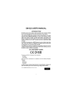
The RC-100 wireless handheld controller (Figure 2) includes a 4x4
keypad and a 97x32 liquid crystal display (LCD). The RC-100 wireless
handheld controller is used to enter information to be displayed on a
scoreboard or display. The handheld operates using a 900 MHz radio
with internal antenna and comes with a rechargeable Ni-MH (Nickel
Metal Hydride) 2000 mAh battery which provides 8-10 hours of
operation. An RC-100 system may include multiple RC-100 wireless
handheld controllers.
The RC-100 wireless Base Station processes information received from
the wireless handheld controllers and sends this information to the
scoreboard or another external controller. Based on the application, an
RC-100 wireless receiver may be mounted inside the display (Figure 3),
or placed in an external tabletop enclosure (Figure 4). An outdoor
enclosure is also available for certain applications.
Figure 3: Internal RC-100 Receiver
Figure 2: RC-100 Wireless
Handheld Controller
Figure 4: External RC-100 Base Station
(Tabletop Enclosure)
Important Installation Range Considerations
The wireless Base Station must be located at least 10' (3 m) from the wireless handheld controller and
no more than 500' (152 m) away. If the wireless handheld is used outside this range, the wireless
handheld signal may drop out. Ideally, the handheld controller should have a clear line-of-sight to
the Base Station antenna. Make sure the Base Station antenna is pointed straight up for best reception
(it should look like a capital “L” when viewed from the side).
RC-100 System Overview
5
Section 3:
RC-100 Base Station
The RC-100 wireless Base Station is used to communicate with all RC-100 wireless handheld
controllers on the same channel setting. The RC-100 wireless Base Station also is used to update
connected displays based with information entered on the wireless handheld controller.
The wireless Base Station includes two switches that must be set to specify the function number and
channel of operation. Refer to Section 3.1 and Section 3.2, respectively. In addition, the Base Station
includes a server/client jumper that must be set to “Client Mode” in some scenarios that feature
multiple displays. Refer to Section 3.4 for more information.
3.1
Function Setting
The desired RC-100 system function must be configured in the wireless Base Station. A list of
possible current functions is shown below, along with the corresponding Function Setting.
Function
Setting
0
1
2
3
4
5
6
7
8
9
A
B
C
D
E
F
Function
(Base Station Server Mode*)
Default Function
(last power up function)
CAN Handheld (Judges') Console
GEN I All Sport Scoreboard Controller
DataTime/Data Master Display Control
Reserved
GEN II All Sport Scoreboard Controller
Reserved
Reserved
Reserved
Reserved
Reserved
Reserved
Reserved
Reserved
Reserved
Reset Memory/Test**
Function
(Base Station Client Mode*)
All Display Groups
Display Group 1
Display Group 2
Display Group 3
Display Group 4
Display Group 2
Reset Memory/Test**
* The function of the Base Station depends on whether it is in Server or Client mode. For a
server Base Station, the Function switch sets up the desired application. For a client Base
Station, the Function switch sets up the display group to which this display belongs.
**Function Setting “F” is a special setting which resets all saved memory parameters back to
defaults. This can be used for situations such as when a password needs to be reset. To use
this function, cycle power to the wireless Base Station with the switch in this position and
leave on for 10 seconds. Remove power, change to the desired function and continue. All
saved memory parameters will be set back to default.
RC-100 Base Station
7
Selecting Functions
Refer to Figure 5 for the wireless Base Station circuit board assembly drawing.
To access the circuit board:
For external Base Station enclosures, remove the two screws securing the top cover,
and lift it off.
For internal Base Stations, refer to the scoreboard/display manual for component
location and access instructions.
After exposing Base Station circuit board, use a small flathead screwdriver to turn the “S2”
rotary switch labeled “FUNCTION” to the desired Function Setting.
Function Select Switch
Figure 5: Function Select Switch (Internal Receiver)
After 5 seconds, the wireless Base Station Server will change its function to match the new
switch setting. (Any connected wireless handheld controllers should change as well.)
When the wireless Base Station Server is turned off and back on, it will always default to
the function set on the switch.
All Sport Scoreboard Controller Function
The All Sport Scoreboard Controller will normally operate with the Function Setting “5”
selected. However, to support legacy products, Gen I mode of operation may be selected by
switching the Function Setting to “2”.
Gen I Operation
Function Setting “2” allows Daktronics Gen I handheld controllers to communicate with Gen
II Base Stations.
Gen II handheld controllers will recognize which generation Base Station they are
communicating with. On first time power-up, the initialization of the radio will take a little
longer while it attempts to recognize which generation Base Station is present.
After a successful connection, the handheld controller will recognize and connect
immediately with that generation of Base Station.
8
RC-100 Base Station
Keep in mind the following when using the Gen I mode of operation:
Gen I handheld controllers or Base Stations will not operate in Function “5”.
All Base Stations operating at the same location must be set to the same Function.
Gen I handheld controllers display ED14905 Version 1.6 or lower on the LCD at
power-up. Gen I Base Stations are labeled ED14906 Version 2.1 or lower.
Gen II handheld controllers display ED14905 Version 2.2 or higher on the LCD at
power-up. Gen II Base Stations are labeled ED14906 Version 2.2 or higher.
3.2
Channel Setting
The wireless Base Station and wireless handheld device use internal radio modules to
communicate. The radios on both the wireless handheld and wireless Base Station device can
be set to any channel ranging from 1-15. “Channel 1” is the default channel used by
Daktronics for single base-station installations.
Refer to Figure 6 for the wireless Base Station circuit board assembly drawing.
To access the circuit board:
For external Base Station enclosures, remove the two screws securing the top cover,
and lift it off.
For internal Base Stations, refer to the scoreboard/display manual for component
location and access instructions.
After exposing Base Station circuit board, use a small flathead screwdriver to turn the “S1”
rotary switch labeled “CHANNEL” to the desired channel.
Channel Select Switch
Figure 6: Channel Select Switch (Internal Receiver)
Note: The wireless handheld and Base Station must be set to the same channel in order to
communicate. To select the channel in the wireless handheld controller, refer to Section 4.1.
Two server Base Stations cannot be powered up in the same area with the same channel
setting, or they will interfere with each other. To avoid this, on power-up the server Base
Station checks to see if there are any other servers located nearby. If another server is
detected, the “IN RANGE” LED (Figure 10) will flash quickly to indicate interference, and
continue to flash until the channel is changed or the conflicting Base Station is turned off.
RC-100 Base Station
9
3.3
Synchronizing Multiple Base Stations and Channel Selection
If two or more server Base Stations need to operate at the same time in the same location,
they must each be set to an independent channel and synchronized accordingly.
The RC-100 wireless system uses frequency-hopping technology to maximize range and
minimize interference from other systems. When multiple server Base Stations are installed
within range of each other (approximately 2000 feet), Base Stations must be able to
synchronize with one another to ensure their hop sequences do not interfere with each other.
This is accomplished by the use of sync groups. A list of the sync groups and their
corresponding channel numbers and channel groups are shown in the table below.
Sync Group
Channel Number
Primary Channel Group
Extended Channel Group
1
2
0
1
All
2, 3, 4, 5
7, 8, 9, 10, 12(C), 13(D), 14(E), 15(F)
3
4
6
11(B)
7, 8, 9, 10
12(C), 13(D), 14(E), 15(F)
12(C), 13(D), 14(E), 15(F)
The “Channel Number,” “Primary Channel Group”, and “Extended Channel Group” entries
correspond to the settings on the CHANNEL rotary switch (Figure 6) and handheld settings
that pertain to the “Sync Group” shown on the same line. Each “Primary Channel Group”
lists the channels that will attempt to synchronize to this sync channel as a first choice. If any
Base Stations set to these “Primary Channels” are within range of a Base Station set to the
corresponding sync channel number, the two Base Stations will sync. The “Extended Channel
Group” lists channels that attempt to synchronize to the corresponding sync channel as a
second or third choice. When these channels are not within range of their primary sync
channel, they will attempt to synchronize to the corresponding sync channel.
When a Base Station is synchronized to a Sync Group, the “IN RANGE” LED (Figure 10) will
flash briefly approximately every 5 seconds with the number of times flashed corresponding
to the sync group: 1 = Channel 0, 2= Channel 1, 3=Channel 6, 4= Channel 11 (B).
Any Base Stations set to channels in the “Channel Groups” section will continuously scan for
sync Base Stations whenever no handheld controllers are connected. This will allow these
boards to be powered up in any sequence and still obtain network synchronization.
10
RC-100 Base Station
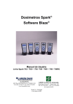
Installations with a Central Base Station
If the installation includes a central Base Station located approximately 3000' (914 m) or closer
to all other Base Stations, a Base Station set on channel 1 may be installed in this location.
All other Base Stations may be set to values in the primary and extended channel groups for
this channel number to avoid interference within the channels. Figure 7 shows an example of
a baseball facility with 9 diamonds, each having its own server Base Station.
Figure 7: Multiple Base Stations w/ Central Location
Note: In order to remain synchronized with one another, no Base Station in the area may be
set to channel 6 or 11. Also, the central Base Station must remain on at all times during the
operation of any other Base Station.
RC-100 Base Station
11
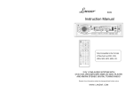
Installations with Base Station Groups
If the installation does not include a central location as described above, or if groups of Base
Stations will be powered down at times, other groups will need to be active and using Sync
Groups 3 and 4 (channels 6 and 11).
An operator may use Sync Groups 3 and 4 (channels 6 and 11) as synchronizing channels for
two other independent groups of scoreboards that may or may not be in range of any other
groups. Figure 8 shows an example of a baseball facility that also has 9 diamonds; however,
in this setup there is no central location and instead uses 3 independent channel groups.
Figure 8: Multiple Base Station Groups
Note: An important limitation exists for channels 1, 6, and 11. Since other channels use these
channels for synchronization purposes, Base Stations on these channels cannot scan during
normal operation, only at power-up. For this reason, these Base Stations must be powered up
in-order (1 first, then 6, then 11) in order to maintain overall network synchronization in the
case where it is needed to have Channels 1, 6, and 11 all powered up at the same time.
12
RC-100 Base Station
3.4
Server/Client Mode Setting
The RC-100 wireless Base Station can operate in either Server Mode or Client Mode,
depending on application requirements. For most applications, the wireless Base Station will
operate in Server Mode, and no change from the default setting will be necessary.
In Server Mode, the wireless Base Station controls all wireless handheld devices, either
through an onboard program (i.e. All Sport® or DataTime®), or by acting as a router to pass
data back and forth between wireless handheld devices and an external control system (such
as an OmniSport® 2000 console). An RC-100 network (on a single channel) contains one and
only one server Base Station device.
In Client Mode, a wireless Base Station relies on another server Base Station to supply it with
data. This client Base Station will typically provide data for a second wireless scoreboard or
display, as needed for All Sport or DataTime functions. Since the Function Select switch is
not needed to select a function when the Base Station is in Client Mode, the function switch
selects the display group instead. For more information refer to Section 3.1.
Refer to Figure 9 for the wireless Base Station circuit board assembly drawing.
To access the circuit board:
For external Base Station enclosures, remove the two screws securing the top cover,
and lift it off.
For internal Base Stations, refer to the scoreboard/display manual for component
location and access instructions.
Server/Client
Select Jumper
Figure 9: Server/Client Select Jumper (Internal Receiver)
Wireless Base Station Server/Client Mode is selected via the “X1” Server/Client Jumper.
Insert the jumper over the top two posts as shown in the “CLIENT” label on the circuit board
to put the wireless Base Station in Client Mode. For Server Mode, leave the jumper over the
bottom two posts (factory default).
Drawing A-317837 in Appendix A shows an example of how a server/client system is used
to operate two game timers at opposite ends of a football field.
RC-100 Base Station
13
3.5
Wireless Base Station LEDs
The wireless Base Station circuit board includes several light-emitting diodes (LEDs) for
diagnostic purposes, as shown in Figure 10 and described in the table that follows.
Figure 10: Wireless Base Station LEDs
#
LED
Color
Function
1
POWER
Green
This LED illuminates when the Base Station or receiver is
connected to a power source
2
CL/RS232 TX
Red
This LED flashes when the Base Station transmits Current
Loop (CL) or RS-232 data via wire:
Current Loop output is used to control scoreboards.
RS-232 output is used to communicate with external
devices, such as a computer with DakTennis™.
3
CL/RS232 RX
Green
This LED flashes when the Base Station receives Current
Loop (CL) or RS-232 data from another device via wire.
4
IN RANGE
Amber
On a server Base Station, this LED flashes several times at
start-up to indicate that it is searching for other server Base
Stations on the same channel within range. If one is found,
this LED flashes continuously to indicate that only one
server Base Station is allowed on a given channel. Once in
operation mode, this LED will either be on or off to indicate
whether or not one or more handheld devices are currently
connected to the Base Station.
On a client Base Station, this LED is on whenever it is
connected to a server Base Station.
This LED also shows sync status. Refer to the Section 3.3.
14
RC-100 Base Station
5
CAN TX
Green
6
CAN RX
Red
This LED flashes when Controller Area Network (CAN) data
is transmitted to a connected device, such as the OmniSport
2000 console.
This LED flashes when Controller Area Network (CAN) data
is received from a connected device, such as the OmniSport
2000 console.
LED Error Diagnostics
The CL/RS232 TX, CL/RS232 RX, IN RANGE, and CAN TX LEDs are also used to display
errors that can occur in wireless Base Station operation. Refer to Section 17 for more
information about these errors.
RC-100 Base Station
15
Section 4:
4.1
RC-100 Handheld Controller
Powering the Controller On and Off
Using the Keypad
Press and hold the <ON/OFF> key momentarily to power on the controller. If the
LCD does not display text within a few seconds, the internal battery is most likely
dead and will need to be recharged (refer to Section 4.3).
Press and hold the <ON/OFF> key for 5 seconds to power off the controller. The
LCD will display a power down message.
Using External Power
Plugging the wireless handheld controller into an external
power source via the power connector on top of the unit will
turn it on (and charge its internal batteries). The wireless
handheld will not turn off if connected to external power.
When connected to external power, the top line of the LCD will
show a power plug (Figure 11).
Figure 11: External Power
Detect Status
When external power is removed and charging is complete, the handheld will power down
after a 5 second prompt to conserve battery power. Press any key during the prompt after
disconnecting external power to keep the handheld controller powered on.
4.2
Battery Operation
When the controller is powered on, an indicator on the top line of
the LCD shows the current battery status (Figure 12). The three
segments within the battery will gradually disappear as the
battery loses its charge.
Figure 12: Battery Status
Idle Time
When using battery power, by default the controller shuts itself off or “sleeps” automatically
after 45 minutes inactivity. The idle time setting may be turned off (refer to Section 4.4), but
to increase battery life, be sure to manually turn the console off when it will be inactive for a
long period of time.
4.3
Battery Recharging
A charger is contained inside the wireless handheld controller for re-charging the batteries.
To recharge the batteries when not in use, simply connect an external power source to the
power connector on top of the unit. A completely discharged battery will take approximately
1.5 hours of fast charging to recharge. For information on battery replacement, see Section 17.3.
A 12 VAC wallpack transformer (Daktronics part # T-1118) is included with the wireless
handheld controller for recharging the batteries and providing external power. Daktronics
also offers a charging station capable of recharging up to 6 units at a time. Refer to Drawing
A-231674 in Appendix A for more information on charging station operation.
RC-100 Handheld Controller
17
4.4
Operation Modes
The RC-100 wireless handheld controller (Figure 2) always operates in one of two modes:
Config or Connect.
Config Mode
Config (“configuration”) mode (Figure 13) is used when a
wireless server Base Station is not controlling a wireless
handheld. Config mode is used to set up operational
settings in the wireless handheld controller.
Figure 13: Config Mode LCD Icon
If the wireless handheld has not yet been configured for a specific channel, the Config mode
will start automatically when the device is first powered on. If it has been previously
configured, the wireless handheld will attempt to connect at the last connected channel.
Configuration mode may be entered at any time by pressing and holding the
<CONFIG> key for 5 seconds.
Use the <↑> and <↓> arrow keys to move through the possible configuration items.
Setting Default Radio Channel Number
Display
PRESS ENT TO
SET CHANNEL
RADI O CHANNEL
DEFAULT: NN*
NN = Current Channel Number
(Default: 1)
Action
Press <ENTER> to set the default radio channel number.
Use the number keys to enter the desired channel
number.
Press <ENTER> again to save the setting.
Note: The channel number should match the setting
on the desired wireless Base Station to connect to on
power-up. Refer to Section 3.2 for more information
on setting the Base Station channel number.
Setting LCD Contrast
Display
PRESS ENT TO
SET CONTRAST
CONTRAST UP - {
CONTRAST DN - }
Action
Press <ENTER> to set the contrast level.
Use the up or down arrow keys on the keypad to set the
desired contrast.
Press <ENTER> again to save the setting.
18
RC-100 Handheld Controller
Setting Power Save Mode
Display
PRESS ENT TO
SET PWR ON TI ME
Power Save: ON
{ or } to Set
Action
Press <ENTER> to set the power off (idle) time. With this
setting enabled, the controller will turn off automatically
after 45 minutes of inactivity.
Use the up or down arrow keys on the keypad to turn the
power save mode ON or OFF.
Press <ENTER> again to save the setting.
Connect Mode
Connect mode (Figure 14) is used when the wireless
handheld is connected to a wireless server Base Station.
In Connect mode, the wireless Base Station determines
the operation of the handheld, and all operation is
specific to the wireless Base Station Function selected.
Figure 14: Connect Mode LCD Icon
Switching to Connect Mode
After all initialization and configuration is complete, the wireless handheld controller will be
ready to connect to a wireless Base Station.
Display
I NI TI ALI ZI NG
RADI O
CONNECTI NG VI A
CHANNEL NN*
Action
Press <CONNECT> to create a connection to an
available wireless Base Station on the channel shown.
Note: The Wireless Base Station must be powered on
and must be set to the specified channel.
If a connection was made, the wireless handheld
will be operating in Connect mode. Refer to the
application-specific sections for operation details.
If a connection could not be made, refer to
Section 17 for information about how to resolve
the problem.
NN = Channel Setting
RC-100 Handheld Controller
19
Signal Strength Indicator
Once a connection has been made, the top line of the LCD
will show the signal strength (Figure 15). This indicator
shows the approximate signal strength of the network
connection. Each successive bar indicates an additional level
Figure 15: Signal Strength
of signal strength between the handheld and Base Station.
When no bars or 1 bar is visible, the connection to the wireless network is likely to be limited,
and the console may occasionally fail to respond. To improve signal strength, move within
range of the Base Station, and remove any obstacles located between the Base Station and
handheld controller if possible. For more information refer to Section 2.
4.5
Common Keys
Several keys on the default keypad layout are common to multiple wireless handheld
applications. These keys are noted in Figure 16. For a description of the function of keys for a
particular application, refer to the application-specific sections of this manual.
1
2
3
4
5
Figure 16: Common RC-100 Keys
#
Key
Function
This key is used to connect to a wireless Base Station.
Refer to Section 4.4 for more information.
1
2
20
CONNECT
Numbers
Pressing <ALT> followed by <CONNECT> when a connection is
made to a wireless Base Station will show Base Station
synchronization and revision information. Refer to Section 17.2 for
more information.
These keys are used for numeric entry functions. While a particular
key may normally be assigned to application-specific functions, in an
Edit routine, they are also used to enter the number shown in the
corner of the key.
RC-100 Handheld Controller
3
Up/Down
Arrows
These keys are used to navigate through menu choices and make
certain selections. Arrows may also be assigned to applicationspecific functions.
ON/OFF
The ON/OFF operation of this key is described in Section 4.1.
CLEAR/NO
The CLEAR operation of this key pertains to editing and data entry
routines. When editing a value, press <CLEAR> to remove that
value. The CLEAR operation may also be used to escape out of an
editing function. If a key was pressed inadvertently, or if the value
being edited should not be changed, pressing <CLEAR> twice exits
the editing routine without modifying the value.
4
The NO operation of this key also pertains to editing and data entry
routines. When a question prompt is shown on the LCD, press this
key to answer the question with a “No.”
ALT
The ALT operation of this key selects alternate actions for certain
application keys. Press this key before pressing another key to
activate a secondary function. Refer to the section following this
table for more information.
CONFIG
The CONFIG operation of this key is described in Section 4.4.
ENTER/YES
The ENTER function of this key pertains to editing and data entry
routines. After editing a value, press <ENTER> to save the change.
The YES function of this key also pertains to editing and data entry
routines. When a question prompt is shown on the LCD, press this
key to answer the question with a “Yes.”
5
EDIT
The EDIT function of this key is used to edit the data associated with
a particular key. For instance, pressing <EDIT> followed by a “+1”
key will allow the operator to manually type in a new value using the
number keys. Refer to the application-specific sections for more
information about which keys have EDIT functionality.
Alternate Function Keys
An alternate function of a key, if applicable, will be shown on the bottom the key below a
horizontal line. Refer to Figure 17 for an example.
Press the key once to run the primary function.
Press <ALT> followed by the key to run the
alternate function.
Figure 17: Key with ALT Functionality
RC-100 Handheld Controller
21
Section 5:
All Sport Applications
This section provides information about the “All Sport” function of the RC-100 wireless Base Station.
Refer to the sections following this section for sport-specific operation.
5.1
Selecting All Sport Applications (Code Numbers)
To select a specific All Sport application (such as baseball, tennis, etc.) the “All Sport”
function must first be set in the wireless Base Station (refer to Section 3.1).
Once the All Sport function has been selected, an All Sport application may be selected by
entering a specific code number on the wireless handheld controller. This number is
typically located on the bottom center of the keypad insert. These numbers are also listed in
Section 5.2 and in the application-specific sections.
Display
ENTER CODE NN
(APPLI CATI ON)
NN = current setting
Action
Enter the code number corresponding to the application
using the number keys on the keypad. When the code
number is correctly selected, a short description will be
shown on the bottom line of the LCD.
Note: Since the wireless Base Station is typically
used with a single application, once the code number
has been set, the wireless Base Station will continue
to use the same code number each time power is
reset. To change code numbers, use the <NEW
CODE> key on the wireless hand-held. Refer to
Section 5.3 for more information.
ENTER CODE NN
NOT FOUND
RESUME PREVI OUS
GAME?
“NOT FOUND” is shown on bottom line of the LCD if the
specified code number was not available. This typically
means either the code was entered incorrectly, or the
Base Station firmware does not support it. If this is a new
code number that is not supported, the Base Station will
need to be either replaced or reprogrammed. Contact
Daktronics Customer Service. Refer to Section 1.2.
If the handheld controller is powered down and powered
back on, the question at left will appear. Press <YES> to
retain the previously-entered settings, or press <NO> to
start a new game under the last code entered.
Note: For RC-100 systems using a Controller Area Network (CAN), it will not be necessary
to enter a sport code. Instead, the RC-100 will automatically detect the operation mode
when it is correctly connected to a controller (typically an OmniSport 2000 console).
All Sport Applications
23
5.2
Keypad Inserts
Keypad inserts allow a single console to control multiple sports and applications. Select the
proper insert from the chart below and slide it into the opening on the bottom of the
controller until it stops. To remove an insert, pull on the tab that extends from the controller.
If an insert is lost or damaged, a copy of the sport insert drawing, located in Appendix B, can
be used until a replacement can be ordered.
Sport/Application
Insert Number
Code
Clock/Score
LL-2613
01
Volleyball
0G-239304
02
Baseball
LL-2605
03
Play Clock / Pitch Timer
LL-2653
05
Segment Timer
LL-2613
06
Tennis
LL-2607
08
Basketball
LL-2632
10
Football
0G-1031603
61, 62
Remote Start/Stop
0G-319079
98
Goal Judge
LL-2663
99
Judge’s Console (CAN)
LL-2606
N/A
Rodeo (CAN)
LL-2608
N/A
Keypad Insert Operation Concepts
A keypad insert identifies the keys required for normal operation of a specific sport or
application. In most cases, pressing a key immediately changes the scoreboard/display. Keys
that require entry of additional information are marked by a dot, (such as <SET TIME •>).
This additional information is usually a number followed by the <ENTER> key.
Some keys are labeled +1. Pressing one of these keys once “increments”, or increases, the
corresponding field on the scoreboard by one (such as score or period). A key with -1
“decrements”, or decreases, by one.
On some inserts, certain keys have been grouped together under the heading HOME or
GUEST. These keys are team keys and work the same for both teams. They affect the
statistics only for that one team. Keys not under one of these headings are Game keys. They
are general keys for the progress of the game (such as period or quarter). Other keys may be
grouped in a similar way to emphasize that they work together.
24
All Sport Applications
5.3
Common All Sport Application Keys
Several All Sport applications provide keys with the same functionality, as described below.
Note: For other common wireless handheld keys, refer to Section 4.5.
New Code (Alternate Function)
The New Code key (Figure 18) is used to select a new code
number and change the current All Sport application.
Applies to: Baseball, Basketball, Clock/Score, Football, Goal
Judge, Play Clock/Pitch Timer, Segment Timer, Tennis, Volleyball
Figure 18: New Code Key
Display
PRESS ENT TO
SELECT NEW CODE
Action
This key is typically implemented as an alternate function.
Press <ALT> followed by <NEW CODE>.
Press <ENTER> to select a new code number. Refer to
Section 5.1.
Note: All data for the current application will be lost.
Press <CLEAR> to cancel and resume normal operation.
New Game (Alternate Function)
The New Game key (Figure 19) is used to reset all current game
data for a specific application. Use it to prepare for a new game by
removing all data from the display.
Applies to: Baseball, Basketball, Clock/Score, Football, Volleyball
Figure 19: New Game Key
Display
PRESS ENT TO
SELECT NEW GAME
Action
This key is typically implemented as an alternate function.
Press <ALT> followed by <NEW GAME>.
Press <ENTER> to start a new game.
Note: All data for the current or last game in progress
will be lost.
Press <CLEAR> to cancel and resume normal operation.
All Sport Applications
25
Start
Press <START> (Figure 20) to start the main clock.
Applies to: Baseball, Basketball, Clock/Score, Football, Play Clock/
Pitch Timer, Remote Start/Stop, Segment Timer, Tennis
Figure 20: Start Key
Stop
Press <STOP> (Figure 21) to stop the main clock.
Applies to: Baseball, Basketball, Clock/Score, Football, Play Clock/
Pitch Timer, Remote Start/Stop, Segment Timer, Tennis
Figure 21: Stop Key
Set Time
The Set Time key (Figure 22) is used to set or adjust the game time
after the game clock has been stopped (or before it has started).
Applies to: Basketball, Clock/Score, Football, Play Clock/Pitch
Timer, Segment Timer, Tennis
Figure 22: Set Time Key
Display
TI ME EDI T
SET
CURR
MM:SS.T*
MM:SS.T = minutes, seconds,
tenths of a second
(Only basketball supports tenths
of a second; baseball supports
hours, minutes, and seconds)
CLOCK RUNNI NG
MM:SS
MM:SS = minutes, seconds
Action
This key is typically implemented as an Alternate
function. Press <ALT> followed by <SET TIME •> to
display the current time of the clock.
To change the time, enter the desired value the using
the number keys on the keypad and press <ENTER>.
Press <CLEAR> twice to cancel any changes and
return to the game.
If the clock is running when the <SET TIME •> is
pressed, the message at left will appear briefly. This
feature may be used to view the current clock time on
the controller.
UP/DN (Alternate Function)
The UP/DN key (Figure 23) is typically the alternate function of the
Set Time key. This key lets the operator select whether the game
clock counts up to the set time or counts down from the set time.
Applies to: Basketball, Clock/Score, Football, Play Clock/Pitch
Timer, Segment Timer, Tennis
26
Figure 23: UP/DN Key
All Sport Applications
Display
MAI N CLOCK-DOWN}
1-UP 2-DOWN
Action
This key is typically implemented as an alternate
function. After the main clock has been stopped, press
<ALT> followed by <UP/DN> to set the direction of the
clock.
Press <1> or <2> to select UP or DOWN (default).
The current direction of the clock is shown by an arrow
on the LCD.
Dim (Alternate Function)
The Dim key (Figure 24) sets the dimming level (brightness) of the
display.
Applies to: Baseball, Basketball, Clock/Score, Football, Play Clock/
Pitch Timer, Segment Timer, Tennis, Volleyball
Display
DI MMI NG
LEVEL(O-9): NN%
NN = current level
NONE = bright <0>
90% =
<1>
80% =
<2>
70% =
<3>
60% =
<4>
50% =
<5>
40% =
<6>
30% =
<7>
20% =
<8>
10% =
<9>
Figure 24: Dim Key
Action
This key is typically implemented as an alternate
function Press <ALT> followed by <DIM> to view the
current dimming level.
Press <0> through <9> to change the dimming level.
Press <ENTER> to save.
Press <CLEAR> to cancel and resume normal
operation.
Note: The incremental dim levels pertain only to
outdoor LED products. Indoor LED and
incandescent products only support one level of
dimming at 50%.
Manual Horn
Press the <MANUAL HORN> key (Figure 25) to sound the horn.
The horn sounds as long as the key is pressed and stops sounding
when the key is released.
Applies to: Basketball, Clock/Score, Football, Remote Start/Stop,
Segment Timer, Tennis
All Sport Applications
Figure 25: Manual
Horn Key
27
Auto Horn
Use the Auto Horn key (Figure 26) to set whether the horn sounds
automatically when the main clock reaches 0:00.
Applies to: Basketball, Clock/Score, Football, Segment Timer
Note: For Football, the Auto Horn is an alternate function.
Display
AUTO HORN-ON {
1-ON, 2-OFF
Figure 26: Auto
Horn Key
Action
Press <AUTO HORN> and then press <1> or <2> to
select ON (default) or OFF.
When Auto Horn is enabled, a small ‘h’ will appear under the clock
direction arrow on the LCD. Figure 27 shows an example where the
clock is counting down and the auto horn is enabled.
Figure 27: Auto
Horn Indicator
28
All Sport Applications
Section 6:
Clock/Score Operation
Sport Insert: LL-2613
Code: 01 (Use Code 11 for optimized server/client operation.)
The sport insert drawing is located in Appendix B. If an insert is lost or damaged, a copy of the insert
drawing can be used until a replacement arrives. Refer Section 4.1 for information on starting the
console and Section 5.3 for additional All Sport application keys.
6.1
Clock Score Keys
Home/Guest Score +1, -1
Display
HOME SCORE
NN
Action
+ 1
HOME SCORE
EDI T NN*
NN = current setting
Press the appropriate HOME or GUEST <SCORE +1>
or <SCORE -1> key to increment or decrement the total
number of points for the team.
To manually change values, first press <EDIT> then
either <SCORE +1> or <SCORE -1> to display the
current setting. Enter the correct number using the
keypad and press <ENTER> to save.
Period +1
Display
PERI OD +1
N
PERI OD EDI T
N *
NN = current setting
Action
Press <PERIOD +1> to increment the current period
number.
To manually change values, first press <EDIT> then
<PERIOD +1> to display the current setting. Enter the
correct number using the keypad and press <ENTER>
to save.
Set TOD (Alternate Function)
Display
SET TI ME OF DAY
12HR HH:MM:SS*
HH:MM:SS = hours, mins, secs
Clock/Score Operation
Action
Press <ALT> followed by <SET TOD> to set the Time of
Day. Enter the correct number using the keypad and
press <ENTER> to save. The time of day clock is now
displayed, if the scoreboard has that capability.
29
Section 7:
Volleyball Operation
Sport Insert: 0G-239304
Code: 02
The sport insert drawing is located in Appendix B. If an insert is lost or damaged, a copy of the insert
drawing can be used until a replacement arrives. Refer Section 4.1 for information on starting the
console and Section 5.3 for additional All Sport application keys.
7.1
Volleyball Keys
Home/Guest Score +1, -1
Display
HOME SCORE
NN
Action
+ 1
Press the appropriate HOME or GUEST <SCORE +1>
or <SCORE -1> key to increment or decrement the total
number of points for the team.
To manually change values, first press <EDIT> then
either <SCORE +1> or <SCORE -1> to display the
current setting. Enter the correct number using the
keypad and press <ENTER> to save.
HOME SCORE
EDI T NN*
NN = current setting
Home/Guest Won +1, -1
Display
HOME WON
NN
HOME WON
EDI T NN*
NN = current setting
Volleyball Operation
Action
+ 1
Press the appropriate HOME or GUEST <WON +1> or
<WON -1> key to increment or decrement the total
number of games won for the team.
To manually change values, first press <EDIT> then
either <WON +1> or <WON -1> to display the current
setting. Enter the correct number using the keypad and
press <ENTER> to save.
31
Reset Game Score
Display
RESET GAME?
ENTER TO ACCEPT
Action
Press <RESET GAME SCORE> followed by <ENTER>
to reset both home and guest scores to zero. This key is
used to clear the Game Score fields at the beginning of
each match.
Game +1, -1
Display
GAME # +1
N
GAME #
EDI T N*
N = current setting
32
Action
Press <GAME +1> to increment the current game
number, or press <GAME +1> to decrement the number.
To manually change values, first press <EDIT> then
either <GAME +1> or <GAME -1> to display the current
setting. Enter the correct number using the keypad and
press <ENTER> to save.
Volleyball Operation
Section 8:
Baseball Operation
Sport Insert: LL-2605
Code: 03
The sport insert drawing is located in Appendix B. If an insert is lost or damaged, a copy of the insert
drawing can be used until a replacement arrives. Refer Section 4.1 for information on starting the
console and Section 5.3 for additional All Sport application keys.
8.1
Baseball Keys
Home/Guest Score +1, -1
Display
HOME SCORE
NN
Action
+ 1
HOME SCORE
EDI T NN*
NN = current setting
Press the appropriate HOME or GUEST <SCORE +1>
or <SCORE -1> key to increment or decrement the
total number of runs for the team.
To manually change values, first press <EDIT> then
either <SCORE +1> or <SCORE -1> to display the
current setting. Enter the correct number using the
keypad and press <ENTER> to save.
Out +1, Inning +1
Display
Action
Press <OUT +1> or <INNING +1> to increment the
total outs or innings, respectively. The numbers will
immediately update on the LCD.
I NNI NG # EDI T
NN*
NN = current setting
To manually change values, first press <EDIT> then
<OUT +1> or <INNING +1> to display the current
setting. Enter the correct number using the keypad and
press <ENTER> to save.
Ball, Strike, Clear Ball & Strike
Press <BALL +1> or <STRIKE +1> to increment the ball and strike digits.
The respective numbers will immediately update on the LCD.
Press <CLEAR BALL & STRIKE> to clear the digits to zero.
Note: If the ball count value is 4 when <BALL +1> is pressed, the value is blanked out.
If the strike count value is 3 when < STRIKE +1> is pressed, the value is blanked out.
Baseball Operation
33
Hit, Error
Display
ERROR ON
Action
Press the <HIT> or <ERROR> key to turn on the Hit or
Error indicator or digits.
The message at left will appear briefly.
Time, At Bat, H/E (Alternate Function)
The <TIME>, <AT BAT>, and <H/E> alternate function keys are used to select what is
shown on the two time digits. First press the <ALT> key and then one of the above keys to
select what is displayed on the two time digits. If <TIME> is selected, they will show two
digits of time. If <AT BAT> is selected, they will show the player At Bat. If <H/E> is selected,
they will show an ‘H’ or an ‘E’ on the first digit when <HIT> or <ERROR> is pressed.
Time/At Bat
If the controller is set to show the time, the <TIME/AT BAT > key operates like the standard
<SET TIME> key (refer to Section 5.3). If the controller is set to show AT BAT, it will operate
as shown below.
Display
AT BAT: EDI T
NN*
Action
Press the <TIME/AT BAT > key, enter the current
batter number, and then press <ENTER>.
NN = current setting
34
Baseball Operation
Section 9:
Play Clock & Pitch Timer Operation
Sport Insert: LL-2653
Code: 05
The sport insert drawing is located in Appendix B. If an insert is lost or damaged, a copy of the insert
drawing can be used until a replacement arrives. Refer Section 4.1 for information on starting the
console and Section 5.3 for additional All Sport application keys.
9.1
Play Clock & Pitch Timer Keys
Set Reset 1, Set Reset 2
Display
TI ME EDI T
RESET 1 MM:SS*
Action
Press <SET RESET 1 > or <SET RESET 2 > to set
the current Reset 1 or Reset 2 value, respectively, for
the play clock/pitch timer.
MM:SS = minutes, seconds
To change the time, enter the desired value the using
the number keys on the keypad and press <ENTER>.
Reset 1, Reset 2
Press <RESET 1> to return the timer to the Reset 1 value configured above.
Press <RESET 2> to return the timer to the Reset 2 value configured above.
For more information about play clock setups featuring server/client Base Stations, refer to
Drawing A-317837 in Appendix A.
Play Clock & Pitch Timer Operation
35
Section 10: Segment Timer Operation
Sport Insert: LL-2613
Code: 06
The sport insert drawing is located in Appendix B. If an insert is lost or damaged, a copy of the insert
drawing can be used until a replacement arrives. Refer Section 4.1 for information on starting the
console and Section 5.3 for additional All Sport application keys.
10.1 Segment Timer Information
The segment timer is used to time events such as practice sessions. The operation of the
segment timer is determined by 40 segments of pre-programmed length. The segment timer
will count down starting at the segment number that is set as First Segment. When the first
segment is completed, the segment timer will count the Interval Time and proceed with the
next segment. The timer will continue counting segments until the segment number that is
set as Last Segment is counted down. It then will reset to the segment saved as the First
Segment and will either begin counting down or pause for the <START> key to be pressed,
depending on the Auto Stop At Last Seg setting. To stop the timer after each segment is
completed, use the Auto Stop feature.
The First Segment and Last Segment values can be used to set up specific practice sessions.
For example, the practice session for one sport could be programmed to use segments 1-10,
while another might use segments 11-20. Set the First Segment and Last Segment values to
the desired segment numbers for the session, and the console will count down each of the
segments in order, either stopping on the last segment or looping through included segments
again, based on the Auto Stop At Last Seg setting.
The default First Segment value is 1. The default value for the Last Segment is 40.
10.2 Segment Timer Keys
First/Last Segment
Display
FI RST SEG NN*
LAST SEG XX
NN = current first segment
XX = current last segment
Action
Press the <FIRST/LAST SEGMENT> key. This setting
determines the first and last segment in a range of
segments to run when <START> is pressed.
Enter the First Segment value and press <ENTER>.
Enter the Last Segment and press <ENTER> to exit.
The controller will be reset to the segment saved as
First Segment when the <RESET TO 1ST SEGMENT>
key is pressed.
The controller automatically resets to the segment
saved as First Segment after the segment saved as
Last Segment is completed.
Segment Timer Operation
37
Segment Number/Time
Display
SEGMENT: NN*
TI ME EDI T
Action
Press <SEG. NO. TIME > to set individual segment
times.
Enter the segment to be edited using the number keys
on the keypad and press <ENTER>.
SEGMENT: NN
TI ME EDI T MM:SS*
NN = segment number
MM:SS = minutes, seconds
Enter the time for the segment using the number keys
on the keypad and press <ENTER> to accept the time
and move to the next segment time.
Press <ENTER> again to exit the function.
Interval Time
The interval time is the time between each segment.
Display
I NTERVAL TI ME:
MM:SS*
MM:SS = minutes, seconds
Action
Press <INTERVAL TIME > to display the current value
of interval time on the bottom line of the LCD. Enter the
interval time using the number keys on the keypad and
press <ENTER> to accept the time.
If the interval time is set to 00:00, no interval time will be
counted.
DI SPLAY I NTERVAL
1-YES 2*NO
* = current setting
This setting determines whether the interval count will
be displayed on the scoreboard.
Press <1> to display the interval time on the scoreboard.
Press <2> to disable interval time display. The interval
time will be displayed only on the controller.
Notes: Regardless of this setting, the value saved in
interval time will be counted down between
segments.
Set the interval time to 0:00 if no interval between
segments is desired.
When the interval time is being displayed, the
segment number on the scoreboard flashes to
indicate that the time displayed is interval time.
38
Segment Timer Operation
Copy Range
This key sets a range of segments to a specific time value.
Display
COPY: MM:SS *
SEG XX TO YY
MM:SS = minutes, seconds
XX = starting segment value
YY = ending segment value
Action
Press <COPY RANGE •>, enter the time to be copied
using the number keys on the keypad, and then press
<ENTER> to move to the next field.
Enter the first and last segments that will have this time.
When the last segment in the copy range is set, the
menu will be exited.
Once completed, all segments from XX to YY (inclusive)
will be set to the specified time.
Auto Stop
This key is the auto stop function of the console.
Note: To set the console to stop after the last segment in the series is completed, the auto
stop at each segment setting must be set to NO.
Display
STOP AT EACH SEG
1-YES 2*NO
* = current setting
Action
Press <AUTO STOP> to enter this menu.
Press <1> to set the controller to stop after each
segment is completed and wait for the <START> key
to proceed with the next segment.
Press <2> to set the controller to automatically begin
the next segment when each segment is completed.
The controller will prompt for the auto stop at last
segment setting:
STOP AT LAST SEG
1*YES 2-NO
* = current setting
Segment Timer Operation
Press <1> to set the controller to stop when the last
segment has been completed.
Press <2> to set the controller to start over at the
first segment when the last segment is completed.
39
Warning Time
Display
WARNI NG TI ME
MM:SS*
MM:SS = minutes, seconds
Action
Press <WARNING TIME >, enter the time in minutes
and seconds and press <ENTER>.
Enter 00:00 for no warning time (default).
When the warning time is reached, the segment number
flashes until the main clock reaches zero.
Current Segment +1
Display
Action
Press <CURRENT SEGMENT +1> to increment the
segment number. The segment number and segment
time will immediately update on the LCD.
CURRENT SEGMENT:
EDI T
NN*
NN = current setting
To manually change values, first press <EDIT> then
<CURRENT SEGMENT +1> to display the current
setting. Enter the correct number using the keypad and
press <ENTER> to save.
Reset Current Segment
Press <RESET CURRENT SEGMENT> to reset the segment time to the value specified by
the current segment. The segment number will remain at the current value.
Reset to First Segment
Press <RESET TO FIRST SEGMENT> to reset the segment number and segment time to the
values saved as the first segment.
Note: The Reset to First Segment function is disabled while the clock is running.
40
Segment Timer Operation
Section 11: Tennis Operation
Sport Insert: LL-2607
Code: 08
The sport insert drawing is located in Appendix B. If an insert is lost or damaged, a copy of the insert
drawing can be used until a replacement arrives. Refer Section 4.1 for information on starting the
console and Section 5.3 for additional All Sport application keys.
11.1 Court Selection
Multiple wireless handheld controllers may be connected to a single wireless Base Station in
the Tennis application. Each connected handheld controller will operate a specific court, and
the controller number for the handheld is selected when powered up.
Display
ENTER CONTROLLER
NUMBER NN*
NN = current setting
ERROR - NUMBER
TAKEN
ERROR - I NVALI D
NUMBER
Action
Enter the controller number for the court that this
particular handheld will operate and then press
<ENTER>.
Typically, controller 1 would run court 1, controller 2
would run court 2, and so on. Some systems may be set
up differently.
If the controller number entered has already
been selected, the error message at left will
display. Select another number.
If the controller number entered is too high, the
error message at left will display. Select another
number.
11.2 Tennis Keys
Serve
Display
TOP SERVE
ON
Tennis Operation
Action
Press the appropriate TOP or BOTTOM <SERVE> key
to turn the serve indicators ON or OFF for the respective
player/team.
41
Game +1
Display
Action
GAMES WON +1
SET X TOP Y
Press the appropriate TOP or BOTTOM <GAME +1>
key to increment the number of games won in the
current set for the respective player/team.
GAMES WON EDI T
SET X TOP Y
To manually change values, first press <EDIT> then
<GAME +1> to display the current setting. Enter the
correct number using the keypad and press <ENTER>
to save.
X = current set
Y = current games won
Point
Display
Action
Press the appropriate TOP or BOTTOM <POINT> key
to increment the total points for the respective player/
team. The current point values will immediately update
on the LCD. The points will increment as 15, 30, 40 AD
or GA. If Tie Break scoring mode is selected, the points
will increment by 1.
TOP=NN* BOT=
EDI T TOP
To manually change values, first press <EDIT> then
<POINT> to display the current setting. Enter the correct
number using the keypad and press <ENTER> to save.
NN = current setting
Reset Game
Press <RESET GAME> to reset the player points values for the current game.
Tie Break
Press <TIE BREAK> to set the mode of scoring to Tie Break mode. In Tie Break scoring
mode, points for each player are incremented by one when the <POINTS> key is pressed.
Note: Tie Break scoring mode may only be selected when both player point values are 0.
To change scoring mode back to normal, use the <RESET GAME> key.
42
Tennis Operation
TOD/Game
This key toggles the controller between displaying Game Time or Time of Day (TOD). It also
allows the user to change the time of day.
Display
SET TI ME OF DAY
12HR HH:MM:SS*
HH:MM:SS = hours, mins, secs
Action
Press <TOD/GAME> to set the Time of Day. Enter the
correct number using the keypad and press <ENTER> to
save. The time of day clock is now displayed, if the
scoreboard has that capability.
Set +1
Display
Action
Press <SET +1> to increment the current set number.
The new set number and games won values will
immediately update on the LCD.
SET EDI T
NN
NN = current setting
I NVALI D SET
PLEASE RE-ENTER
To manually change values, first press <EDIT> then
<SET +1> to display the current setting. Enter the
correct number using the keypad and press <ENTER>
to save.
If the set number entered is invalid, the error message
at left will display. Enter another set number.
Reset Match (Alternate Function)
Display
PRESS ENT TO
START NEW MATCH
Action
Press <ALT> and then <MATCH>. Press <ENTER> to
confirm resetting the current match.
All set scores and the current game score will be
cleared, and the set number will be set to 1.
Matches Won (Alternate Function)
Display
MATCHES WON EDI T
TOP
NN*
Tennis Operation
Action
Press <ALT> and then the appropriate TOP or
BOTTOM <MATCHES WON> key to edit the matches
won for the respective player/team. Enter the correct
number using the keypad and press <ENTER> to save.
43
Next Match (Alternate Function – DakTennis Only)
Display
NEXT MATCH
SELECTED
Action
Press <ALT> and then <NEXT MATCH> to tell the
DakTennis™ software to switch to the next match.
The LCD will show that the next match was selected.
Winner (Alternate Function – DakTennis Only)
Display
TOP WI N
ON
Action
Press <ALT> and then <WINNER> for the respective
TOP or BOTTOM player to tell the DakTennis™
software to set the player as the winner if currently off or
clear the winner if currently on. The LCD will show the
status of the winner being set ON or OFF.
For more information, refer to the DakTennis Version 3 Installation & Operation Manual
(DD1965926), available online at www.daktronics.com/manuals.
44
Tennis Operation
Section 12: Basketball Operation
Sport Insert: LL-2632
Code: 10 (Use Code 20 for optimized server/client operation.)
The sport insert drawing is located in Appendix B. If an insert is lost or damaged, a copy of the insert
drawing can be used until a replacement arrives. Refer Section 4.1 for information on starting the
console and Section 5.3 for additional All Sport application keys.
12.1 Basketball Keys
Home/Guest Score +1, +2, (+3, -1)
Display
Action
HOME SCORE
NNN
+ 1
Press the appropriate HOME or GUEST <SCORE +1>
or <SCORE +2> key to increment the total number of
points for the respective team by the value on the key.
HOME SCORE
NNN
+ 3
To increment the score by 3, press <ALT> and then
<SCORE +3>.
HOME SCORE
NNN
- 1
To decrement the score by 1, press <ALT> and then
<SCORE -1>.
To manually change values, first press <EDIT> then any
<SCORE> key to display the current setting. Enter the
correct number using the keypad and press <ENTER>
to save.
HOME SCORE
EDI T NNN*
NNN = current setting
Fouls +1
Display
HOME FOULS
NN
HOME FOULS
EDI T NN*
NN = current setting
Basketball Operation
Action
+ 1
Press the appropriate HOME or GUEST <FOULS +1>
key to increment the fouls value for the respective team.
To manually change values, first press <EDIT> then
<FOULS +1> to display the current setting. Enter the
correct number using the keypad and press <ENTER>
to save.
45
Possession
Display
Action
Press <POSS> to light the appropriate indicator. Each
press will turn on the opposite team’s possession light.
HOME POSSESSI ON
LI GHT ON
Period +1
Display
Action
PERI OD +1
NN
Press <PERIOD +1> to increment the current period
number.
PERI OD EDI T
N *
To manually change values, first press <EDIT> then
<PERIOD +1> to display the current setting. Enter the
correct number using the keypad and press <ENTER>
to save.
NN = current setting
Set TOD (Alternate Function)
Display
Action
SET TI ME OF DAY
12HR HH:MM:SS*
HH:MM:SS = hours, mins, secs
Press <ALT> followed by <SET TOD> to set the Time of
Day. Enter the correct number using the keypad and
press <ENTER> to save. The time of day clock is now
displayed, if the scoreboard has that capability.
1/10 SEC (Alternate Function)
Display
TI ME MM:SS.T
H- O G- O
Action
Press <ALT> followed by <1/10 SEC> to toggle the 1/10
second setting of the clock. The clock on the LCD will
show time to tenths of a second.
MM:SS.T = minutes, seconds,
tenths of a second
46
Basketball Operation
Bonus (Alternate Function)
Display
HOME BONUS
LI GHT 1-ON-1
HOME BONUS
LI GHT 2-SHOT
HOME BONUS
LI GHT OFF
Basketball Operation
Action
Press <ALT> followed by the appropriate HOME or
GUEST <BONUS> key to turn on the 1-ON-1 bonus
light.
Press <ALT> followed by the same <BONUS> key a
second time to turn on the 2 SHOT bonus light.
Press <ALT> followed by the same <BONUS> key a
third time to turn on the bonus light OFF.
47
Section 13: Football Operation
Sport Insert: 0G-1031603
Code: 61, 62
The sport insert drawing is located in Appendix B. If an insert is lost or damaged, a copy of the insert
drawing can be used until a replacement arrives. Refer Section 4.1 for information on starting the
console and Section 5.3 for additional All Sport application keys.
13.1 Football Keys
Home/Guest Score +1, +6, (+3, -1)
Display
Action
HOME SCORE
NNN
+ 6
HOME SCORE
NNN
+ 3
HOME SCORE
NNN
- 1
HOME SCORE
EDI T NNN*
NNN = current setting
Press the appropriate HOME or GUEST <SCORE +1>
or <SCORE +6> key to increment the total number of
points for the respective team by the value on the key.
To increment the score by 3, press <ALT> and then
<SCORE +3>.
To decrement the score by 1, press <ALT> and then
<SCORE -1>.
To manually change values, first press <EDIT> then any
<SCORE> key to display the current setting. Enter the
correct number using the keypad and press <ENTER>
to save.
Ball On
Display
BALL ON EDI T
NN*
Action
Press <BALL ON •> to set the yard line of the ball.
Enter the correct number using the keypad and press
<ENTER> to save.
NN = current setting
Football Operation
49
Down +1
Display
Action
DOWN +1
N
Press the <DOWN +1> key to increment the down
number. The value increments from 1 to 4 then repeats.
DOWN EDI T
N*
To manually change values, first press <EDIT> then
<DOWN +1> to display the current setting. Enter the
correct number using the keypad and press <ENTER>
to save.
N = current setting
TOL -1
Display
Action
HOME TOL
N
- 1
HOME TOL
EDI T N*
N = current setting
Press the appropriate HOME or GUEST <TOL -1> to
decrement the number of Time Outs Left (TOL) for the
respective team. By default, each team starts the game
with 3 time outs.
To manually change values, first press <EDIT> then
<TOL -1> to display the current setting. Enter the
correct number using the keypad and press <ENTER>
to save.
To Go
Display
TO GO
NN*
Action
EDI T
Press <TO GO •> to set the distance to go until first
down. Enter the correct number using the keypad and
press <ENTER> to save.
NN = current setting
Possession (Alternate Function)
Display
HOME POSS
LI GHT ON
50
Action
Press <ALT> followed by the appropriate HOME or
GUEST <POSS> key to light the possession indicator
for the respective team. A second press will turn the
indicator off, as will turning on the opposing team’s
indicator.
Football Operation
QTR +1
Display
QUARTER +1
N
QUARTER EDI T
N *
N = current setting
Football Operation
Action
Press <QTR +1> to increment the current quarter
number.
To manually change values, first press <EDIT> then
<QTR +1> to display the current setting. Enter the
correct number using the keypad and press <ENTER>
to save.
51
Section 14: Remote Start/Stop Operation
Sport Insert: 0G-319079
Code: 98
The sport insert drawing is located in Appendix B. If an insert is lost or damaged, a copy of the insert
drawing can be used until a replacement arrives. Refer Section 4.1 for information on starting the
console and Section 5.3 for additional All Sport application keys.
14.1 Remote Start/Stop Keys
Start
Display
Action
REM START/STOP
CLOCK OFF
When the clock is stopped, the LCD will show the clock
status on the bottom line as OFF.
CLOCK START
CLOCK RUN
Press <START> and the top line of the LCD will briefly
show the function, and then the clock status will change
to RUN.
Stop
Display
Action
REM START/STOP
CLOCK RUN
When the clock is already running, the LCD will show the
clock status on the bottom line as RUN.
CLOCK STOP
CLOCK OFF
Press <STOP> and the top line of the LCD will briefly
show the function, and then the clock status will change
back to OFF.
Manual Horn/Reset
Depending on the current jack the Base Station is connected to on the All Sport 5000
controller, this key will have different functions:
When connected to the J4 (main clock) jack, the key functions as a manual horn.
When connected to the J7 (shot/play clock) jack, the key functions as a timer reset.
For more information about Remote Start/Stop setups, refer to Drawing B-319037 in
Appendix A.
Remote Start/Stop Operation
53
Section 15: Goal Judge Operation
Sport Insert: LL-2663
Code: 99
The sport insert drawing is located in Appendix B. If an insert is lost or damaged, a copy of the insert
drawing can be used until a replacement arrives. Refer Section 4.1 for information on starting the
console and Section 5.3 for additional All Sport application keys.
Note: When using the RC-100 as a Goal Judge console, operators should disable the auto power
off setting (Power Save Mode). Refer to Section 4.4.
15.1 Goal Judge Keys
Goal Light On/Off
Display
GOAL JUDGE
GOAL KEY PRESSED
Action
Press <GOAL LIGHT ON/OFF> to turn the goal lights
ON if they are off, or OFF if they are already on.
For more information about goal judge setups, refer to Drawing A-317405 in Appendix A.
Goal Judge Operation
55
Section 16: CAN Handheld Operation
This section describes operation details specific to CAN (Controller Area Network) handheld
operations. CAN handheld functionality is used when handheld operation is controlled by a device
on the CAN network such as the OmniSport 2000 timing console. Refer to Drawing A-230608 in
Appendix A for typical CAN setup information.
16.1 Common CAN Handheld Operation
Display
WAI TI NG FOR
EXTERNAL CONTROL
Action
When the message at left is shown on the LCD, the
Base Station is waiting to be connected to an external
device on the CAN network.
When a CAN device is detected, the LCD will update to
show application-specific information.
16.2 Diving & Synchronized Swimming Operations
Sport Insert: LL-2606
Refer to the Judge’s Console section of the OmniSport 2000 Timing Console Operations
Manual (ED-13312) for application-specific operation instructions.
16.3 Rodeo Operations
Sport Insert: LL-2608
Refer to the Judge’s Console section of the OmniSport 2000 Rodeo Timer Operations
Manual (ED-14843) for application-specific operation instructions.
CAN Handheld Operation
57
Section 17: Troubleshooting
17.1 Handheld Controller Error Messages
Display
NO SEVER FOUND
ON CHANNEL NN
NN = current setting
ENT TO RETRY
CLEAR SETS CHAN
NO RESPONSE
ON CHANNEL NN
NN = current setting
ENT TO RETRY
CLEAR SETS CHAN
ERROR - THI S
CHANNEL I N USE
Cause/Solution
The wireless handheld could not find a server on the
specified channel.
Make sure the wireless Base Station is powered
on, and is set for the specified channel.
Make sure the handheld is within minimum and
maximum range limits (refer to Section 2).
Press <ENTER> to retry the connection (if the
handheld was just moved in range or the
wireless Base Station has been correctly
configured).
Press <CLEAR> to set the channel number to a
different channel and retry.
The wireless handheld did find a server on the specified
channel, but the server did not respond.
Make sure the handheld is within minimum and
maximum range limits (refer to Section 2).
Cycle power to the wireless Base Station and
retry the connection.
Make sure that there are no other wireless Base
Stations within range on the same channel.
Try a different channel if necessary.
Press <ENTER> to retry the connection (if the
handheld was just moved in range or the
wireless Base Station has been correctly
configured).
Press <CLEAR> to set the channel number to a
different channel and retry.
The message at left is displayed if another wireless
handheld controller is currently connected to the Base
Station and the application does not permit multiple
handheld units.
Power off any other unused handheld units on the same
channel in the area (refer to Section 4.1).
Troubleshooting
59
Display
Cause/Solution
Although multiple wireless handheld controllers may be
connected to a single Base Station, the following
applications allow only one handheld device to be
connected at a time:
Baseball
Basketball
Clock/Score
Football
Goal Judge
Play Clock/Pitch Timer
Remote Start/Stop
Segment Timer
Volleyball
LOW SI GNAL
STRENGTH
PRESS CLEAR FOR
CONFI G MENU
The Base Station has stopped responding to the
wireless handheld. This could mean any of the following
scenarios are true:
The Base Station was turned off or has lost
power.
The Base Station was changed to a different
channel.
The Base Station and handheld are too far away
or too close (refer to Section 2).
If all of these problems have been checked and the
handheld still shows Low Signal Strength, cycle power
on both the handheld and Base Station.
17.2 Base Station Errors
IN RANGE LED On Start-up
The IN RANGE LED (Figure 10) flashes several times at start-up while the server Base
Station searches for other Base Stations on the same channel within range. If another server
Base Station is found, this LED will flash continuously, indicating that only one server Base
Station is allowed on a given channel.
General Base Station Failures
The wireless Base Station uses the on-board LEDs (Figure 10) to indicate failure status. When
a failure occurs, the CL/RS232 TX, CL/RS232 RX, IN RANGE, and CAN TX LEDs all flash in
a repetitive pattern to indicate the failure type. The LEDs will flash on for a long period of
time, followed by a series of short flashes that give the error type. This sequence will repeat 5
times, after which the Base Station will reset.
If an error sequence is being displayed on the LEDs, first cycle power to the wireless Base
Station by disconnecting power for several seconds and then reconnecting. If the problem
persists, please contact Daktronics Customer Service (refer to Section 1.2).
60
Troubleshooting
Obtaining Base Station Status Information
When connected to a wireless Base Station in any All Sport function, the wireless handheld
can obtain status information about the Base Station. This information includes the Base
Station channel, firmware revision number and date, and whether or not the Base Station is
synchronized to another Base Station in the area.
Display
VN.N MMM DD YYYY
NoSync Chan:CC
Action
Press <ALT> followed by <CONNECT> to display Base
Station status information.
Press any key to return to normal operation.
N.N = firmware revision
MMM = month
DD = date
YYYY = year
CC = channel number
Note: If the Base Station is synchronized to another
Base Station via a sync group, the bottom left corner
of the LCD will display “Sync:” followed by the sync
group number. Refer to Section 3.3.
17.3 Replacing Handheld Battery
To verify the battery is replaceable, look at
the revision number on the back of the unit
(Figure 28). If the assembly is REV 7 or
higher (after August 30, 2007), the battery
may be replaced in the field. Units built
before this date must be sent to Daktronics
to have a new battery installed.
Figure 28: Manufacturing Date & Revision Number
After verifying the correct revision number, follow the steps below to replace the battery.
1.
2.
3.
4.
5.
6.
Remove the two Philips screws (one on the top and one on the bottom).
Separate the bottom half of the case from the top half.
Disconnect the 2-pin battery power cable from the main circuit board, and remove
the battery from the retaining clips (Figure 29).
Install new battery (Daktronics
part # BT-1032) into the retaining
clips and connect the 2-pin cable.
Close the case and tighten the
screws.
Charge the battery as needed
before first use.
Note: Please return used batteries to
a battery recycling center or battery
retailer for proper disposal.
Figure 29: Handheld Unit, Cover Removed
Troubleshooting
61
Appendix A:
Reference Drawings
Drawing Title
Drawing Number
Base Station: Indoor Installation ............................................................................................... A-227465
System Riser Diagram; RC-100, Baseball/Tennis ................................................................... A-230530
System Riser; RC-100, Rodeo/Diving/Sync Swimming ........................................................... A-230608
System Riser; Tennis; Indoor Multi-Court, DakTennis, CG ...................................................... B-231298
Charging Station, Specifications & Operation .......................................................................... A-231674
System Riser; Tennis; Multi-Court, RC-100 Direct ................................................................... B-233254
Base Station: Outdoor Installation ............................................................................................ A-236394
System Riser Diagram: RC-100- MS-2013 .............................................................................. A-244926
System Riser Diagram; DakTennis, Video Control .................................................................. A-251996
Base Station: DistaView Scoreboard Installation ..................................................................... A-266717
Riser Diagram; Goal Indicator System w/ RC 100 ................................................................... A-317405
System Riser Diagram; RC-100 Server/Client Line ................................................................. A-317837
System Riser, RC-100 Game/DOG Clock Remote St/St ......................................................... B-319037
System Riser; Tennis; DakTennis & Remote Base Station.................................................... A-1040167
Reference Drawings
63
TX RX
CL / RS232
IN
TX RX
RANGE
CAN
$9
BALL STRIKE
OUT
GUEST
HOME
INNING
'$.7521,&6,1&
5(9
'$7(
$35
83'$7('5&+$1'+(/'3$57180%(5
83'$7('%2$5'(5$1'7,7/(%/2&.
%<
-)/
7+(&21&(376(;35(66('$1''(7$,/66+2:1217+,6
'5$:,1*$5(&21),'(17,$/$1'35235,(7$5<'2127
5(352'8&(%<$1<0($16:,7+2877+((;35(66('
:5,77(1&216(172)'$.7521,&6,1&
&23<5,*+7'$.7521,&6,1&
5$',2/,1.
6<67(05,6(5',$*5$05&%$6(%$//7(11,6
'5$:1 57$*72:
'$7( '(&
121(
6+((7
5(9
-2%12
3
5 $
$9
POWER
12 VAC
RS232
CAN
POWER
12 VAC
POWER
12 VAC
'$.7521,&6,1&
5(9
'$7(
$35
83'$7('5&+$1'+(/'3$57180%(5
83'$7('%2$5'(5$1'7,7/(%/2&.
%<
-)/
RS232
RS232
CAN
CAN
7+(&21&(376(;35(66('$1''(7$,/66+2:1217+,6
'5$:,1*$5(&21),'(17,$/$1'35235,(7$5<'2127
5(352'8&(%<$1<0($16:,7+2877+((;35(66('
:5,77(1&216(172)'$.7521,&6,1&
&23<5,*+7'$.7521,&6,1&
5$',2/,1.
6<67(05,6(55&52'(2',9,1*6<1&6:,00,1*
'5$:1 57$*72:
'$7( '(&
121(
6+((7
5(9
-2%12
3
5 $
%+
,1'2256&25(%2$5'/$<287
21/<)256,1*/(
&28576&%'6
-%
6&
-%
6&
6&
-%
6&
6%
6&
6&
,167$//127(02/'('6,*1$/
,17(5&211(&7&$%/(6:,7+
6&25(%2$5'
6,*
287
6,*
287
6,*
,1
6,*
287
6,1*/(&28576&%'
:)7
6,1*/(&28576&%'
6,*
287
-%6&)7&$%/(:,7+',63/$<
;38//63/,&(%2;%<27+(5686(
':*)257(50,1$7,21
,16758&7,216
6%;3+21(-$&.-%2;
$%<'$.7521,&6,167$//%<
27+(56
:)7
6,*
,1
6,*
287
:)7
6,*
287
6,*
,1
6,*
287
6,*
287
:)7
6,*
,1
6,*
287
6,*
287
-%
6&
6&
6&
-%
6&
6,*
,1
6,*
287
6,1*/(&28576&%'
6,*
,1
6,1*/(&28576&%'
6,*
,1
$'',7,21$/25'(5('
21/<)256,1*/(&2857
6&%'6(&7,216
:)7
:)7
6,*
,1
6&
6,*
,1
6,*
,1
:)7
-%
-%
6,*
,1
'$.7(11,6&21752//2&$7,21
&/($5/,1(2)6,*+75(48,5('
$%$6(67$7,21.,7
7<3,&$/6(77,1*
)81&7,21 &+$11(/ 6(59(5-803(5(1$%/('
127(6((':*$1'287'225
%$6(67$7,21$,)<281(('
725(027(/2&$7()25%(77(5/,1(2)
6,*+7
:
$
6,*1$/&219(57(5
7<386%726(5,$/
$'$37(56%<
27+(56
/
352'8&7,21/2&$7,21
$//63257&*6(783
$
;-%2;
5(9
5(9
'$.7521,&6,1&
5(9
'$7(
2&7
5(9
'$7(
$35
83'$7('%2$5'72%6,=('$''(''(7$,/6
726+2:,1'2256&25(%2$5'/$<287
83'$7('5&+$1'+(/'3$57180%(5
83'$7('%2$5'(5$1'7,7/(%/2&.
%<
0:0
%<
-)/
'$7(
$''('*(1,,)81&7,21
-$1
'$7(
$8*
%<
-5$
$''('&28576&25,1*',$*5$0
&+$1*('1$0(2)'5$:,1*
%<
7$-
7+(&21&(376(;35(66('$1''(7$,/66+2:1217+,6
'5$:,1*$5(&21),'(17,$/$1'35235,(7$5<'2127
5(352'8&(%<$1<0($16:,7+2877+((;35(66('
:5,77(1&216(172)'$.7521,&6,1&
&23<5,*+7'$.7521,&6,1&
7(11,66&25(%2$5'6
6<67(05,6(57(11,6,1'22508/7,&2857'$.7(11,6&*
'5$:1 57$*72:
'$7( -$1
121(
6+((7
5(9
-2%12
3
5 %
%+
,1'2256&25(%2$5'/$<287
$''21/<)25
6,1*/(&28576&%'6
-%
-%
6&
6&
-%
6&
6&
6%
6&
-%
6&
:)7
-%
6&
6&
-%
6&
6&
,167$//127(02/'('6,*1$/
&$%/(6:,7+6&25(%2$5'
6,*
287
6,*
287
6,*
,1
6,*
287
6,1*/(&28576&%'
6,*
,1
6,*
,1
6,*
287
:)7
6,1*/(&28576&%'
6,*
287
:)7
6,*
,1
6,*
287
:)7
6,*
,1
6,*
287
6,*
,1
6,*
287
6,1*/(&28576&%'
6,*
,1
6,1*/(&28576&%'
6,*
,1
$''21/<)256,1*/(
&28576&%'6(&7,216
:)7
-%6&)7&$%/(:,7+',63/$<
;38//63/,&(%2;%<27+(5686(
':*)257(50,1$7,21
,16758&7,216
:)7
6%;3+21(-$&.-%2;
$%<'$.7521,&6,167$//%<
27+(56
6,*
287
6,*
,1
6,*
287
:)7
6,*
,1
6,*
287
6,*
,1
287'2256&25(%2$5'/$<287
6,1*/(&2857
6,1*/(&2857
36
6,1*/(&2857
36
6,1*/(&2857
36
36
36,17(51$/3:56,*7(50/2&$7,21
(;$&7/</2&$7,21,6'(7(50,1('%<
02'(/385&+$6('
5&$7($&+&2857&20081,&$7,2172
0$,108/7,&28575(&(,9(5
5(9
'$7(
2&7
5(9
'$7(
$35
5(9
'$7(
-$1
83'$7(%2$5'72%6,=(6+2:,1'225$1'287'225
'(7$,/83'$7(6
83'$7('5&+$1'+(/'3$57180%(5
83'$7('%2$5'(5$1'7,7/(%/2&.
$''(')81&7,21*(1,,
5(9
'$7(
$8*
%<
0:0
%<
-)/
%<
-5$
$''('&28576&25,1*',$*5$0
&+$1*('1$0(2)'5$:,1*
'$.7521,&6,1&
%<
7$-
7+(&21&(376(;35(66('$1''(7$,/66+2:1217+,6
'5$:,1*$5(&21),'(17,$/$1'35235,(7$5<'2127
5(352'8&(%<$1<0($16:,7+2877+((;35(66('
:5,77(1&216(172)'$.7521,&6,1&
&23<5,*+7'$.7521,&6,1&
7(11,66&25%2$5'6
6<67(05,6(57(11,608/7,&28575&',5(&7
'5$:1 57$*72:
'$7( )(%
121(
6+((7
5(9
-2%12
3
5 %
TX RX
CL / RS232
IN
TX RX
RANGE
CAN
$9
HOME
DAKTRONICS
GUEST
PERIOD
5(9
'$7(
$35
83'$7('5&+$1'+(/'3$57180%(5
83'$7('%2$5'(5$1'7,7/(%/2&.
%<
'$.7521,&6,1&
-)/
7+(&21&(376(;35(66('$1''(7$,/66+2:1217+,6
'5$:,1*$5(&21),'(17,$/$1'35235,(7$5<'2127
5(352'8&(%<$1<0($16:,7+2877+((;35(66('
:5,77(1&216(172)'$.7521,&6,1&
&23<5,*+7'$.7521,&6,1&
5$',2/,1.
6<67(05,6(5',$*5$05&06
'5$:1 .%,(5%$
.%,(5%$
121(
6+((7
5(9
-2%12
3
5 $
'$7(
-81
AV
NOTES:
VIDEO MATRIX DISPLAY
THIS IS NOT A SCALED DRAWING AND SHOULD BE USED
FOR POWER AND SIGNAL REQUIREMENTS ONLY.
IT IS THE RESPONSIBILITY OF THE ELECTRICAL
INSTALLATION CONTRACTOR TO ENSURE THAT ALL
ELECTRICAL WORK PERFORMED ON SITE MEETS OR
EXCEEDS ALL LOCAL AND NATIONAL ELECTRICAL CODES.
ALL DISPLAYS MUST BE GROUNDED PER ARTICLE 250
AND 600 OF THE NATIONAL ELECTRICAL CODE WITH NO
MORE THAN 10 OHMS GROUND RESISTANCE.
FIBER OPTIC
CABLE RUN IN CONDUIT
MONITOR
VENUS 7000 OR
DMP SYSTEM
USB TO SERIAL
ADAPTOR
PRIMARY
OUTPUT
0
ROCKET
PRINTER
USB
W-1350 (6')
1
2
3
USB
COM
W-1267 (10')
LAPTOP COMPUTER
DAKTENNIS
USER'S KIT
POWER
12 VAC
RS232
CAN
RC-100'S AT COURT LOCATIONS
T-1118
BASE STATION
0A-1110-0030
FUNCTION SETTING = 5
CHANNEL = 1-15
RC-100 WIRELESS HANDHELD: 0A-1110-0053, TYP. @6. INCLUDED
IN RC-100 HANDHELD, CONTROLLER KIT: 0A-1110-0102.
SEE TABLE BELOW FOR CONTENTS OF RC-100 HANDHELD, CONTROLLER KIT:
0A-1110-0102
NOTE:
THE (6) RC-100 CONTROLLERS USE CHANNELS 1-15,
HOWEVER, THE BASE STATION AND HAND HELD
CONTROLLERS MUST BE OPERATING ON THE SAME
CHANNEL. USE CODE 08 FOR TENNIS.
PART ID
RC-100
INSERT KIT
ASSEMBLY #
DESCRIPTION AND OPERATOR INFO
0A-1000-1079
0A-1110-0053
EN-1995
T-1118
CD; SOFTWARE, ALL SPORT MANUALS
RC-100 WIRELESS HANDHELD G2
RC-100 BLACK, SOFT CARRY CASE
TRANSFORMER; 12VAC; WALLPACK 6' CORD
LL-2806
RC-100 TENNIS INSERT USE CODE 08
DAKTRONICS, INC.
REV
DATE:
04
20 MAY 13
REV
DATE:
03
09 OCT 12
REV
DATE:
02
27 APR 12
UPDATED RC-100 INSERT PART # TO LL-2806. ADDED
RC-100 CONTROLLER KIT TABLE.
UPDATED BORDER AND GENERAL DETAILS WITH NEW
INFORMATION
UPDATED RC-100 HANDHELD PART NUMBER
UPDATED BOARDER AND TITLE BLOCK
BY:
SMB
BY:
MWM
BY:
JFL
01
30 JUL 08
TENNIS SCOREBOARD
SYSTEM RISER DIAGRAM; DAKTENNIS, VIDEO CONTROL
DRAWN: TJOHNSON
DATE: 24AUG05
RTAGTOW
NONE
SHEET
CORRECTED WIRE PART #
KZB
THE CONCEPTS EXPRESSED AND DETAILS SHOWN ON THIS
DRAWING ARE CONFIDENTIAL AND PROPRIETARY. DO NOT
REPRODUCE BY ANY MEANS WITHOUT THE EXPRESSED
WRITTEN CONSENT OF DAKTRONICS, INC.
COPYRIGHT 2012 DAKTRONICS, INC.
REV
04
JOB NO:
P1164
E 10 A
251996
AV
DAKTRONICS, INC.
REV
DATE:
03
21 NOV 12
REV
DATE:
02
27 APR 12
UPDATED GOAL LIGHTS
BY:
KZB
UPDATED RC-100 HANDHELD PART NUMBER
UPDATED BOARDER AND TITLE BLOCK
BY:
THE CONCEPTS EXPRESSED AND DETAILS SHOWN ON THIS
DRAWING ARE CONFIDENTIAL AND PROPRIETARY. DO NOT
REPRODUCE BY ANY MEANS WITHOUT THE EXPRESSED
WRITTEN CONSENT OF DAKTRONICS, INC.
COPYRIGHT 2012 DAKTRONICS, INC.
STANDARD INDOOR LED SCOREBOARDS
RISER DIAGRAM: GOAL INDICATOR SYSTEM W/ RC 100
DRAWN: AGEWERT
DATE: 23 AUG 07
MMILLER
JFL
SHEET
REV
03
JOB NO:
P1152
R 01 A
317405
10
20
30
40
50
40
30
20
10
Daktronics
Daktronics
$9
'$.7521,&6,1&
7+(&21&(376(;35(66('$1''(7$,/66+2:1217+,6
'5$:,1*$5(&21),'(17,$/$1'35235,(7$5<'2127
5(352'8&(%<$1<0($16:,7+2877+((;35(66('
:5,77(1&216(172)'$.7521,&6,1&
&23<5,*+7'$.7521,&6,1&
5&6(59(5&/,(17/,1(
6<67(05,6(5',$*5$05&6(59(5&/,(17/,1(
'5$:1 $5,&+7(
'$7( $8*
121(
5(9
'$7(
$35
83'$7('5&+$1'+(/'3$57180%(5
83'$7('%2$5'(5$1'7,7/(%/2&.
%<
-)/
6+((7
5(9
-2%12
3
5 $
%+
5(9
'$7(
),;(')25&/$5,7<
129
5(9
'$7(
$35
5(9
'$7(
$8*
%<
.=%
83'$7('5&+$1'+(/'3$57180%(5
83'$7('%2$5'(5$1'7,7/(%/2&.
$''('$*$0(&/2&.$1'$''('127(6
)25$//63257&21752/
'$.7521,&6,1&
%<
-)/
%<
556
7+(&21&(376(;35(66('$1''(7$,/66+2:1217+,6
'5$:,1*$5(&21),'(17,$/$1'35235,(7$5<'2127
5(352'8&(%<$1<0($16:,7+2877+((;35(66('
:5,77(1&216(172)'$.7521,&6,1&
&23<5,*+7'$.7521,&6,1&
:,5/(66/,1.
6<67(05,6(55&*$0('2*&/2&.5(027(6767
'5$:1 '',1,1*
'$7( 6(3
121(
6+((7
5(9
-2%12
3
( %
J7
J6
J4
J3 J2 J1
ALLSPORT
5010R6
REV
DATE:
02
30 JAN 13
REV
DATE:
01
27 APR 12
ADDED SOME TEXT UPDATES TO THE DATA CABLE RUN
FROM JB1 TO JB2. ADDED USB TO SERIAL PART #, AND
OPTIONAL ALLSPORT RADIO METHOD.
ADDED PART NUMBER FOR RC-100 HANDHELD
BY:
MWM
BY:
JFL
Appendix B:
Sport Inserts
Drawing Title
Drawing Number
Insert; LL-2608, RC-100, Rodeo .............................................................................................. A-231529
Insert: LL-2605- RC-100- Baseball ........................................................................................... A-231530
Insert; LL-2607, RC-100, Tennis .............................................................................................. A-231531
Insert; LL-2606, RC-100, Judges Console ............................................................................... A-231532
Custom Insert; Volleyball, RC-100 ........................................................................................... A-239304
Insert; LL-2613, RC-100 Clock/Score ...................................................................................... A-239307
Insert; LL-2613 Back, RC-100 Segment Timer ........................................................................ A-247621
Insert, LL-2632, RC-100, Basketball ........................................................................................ A-253583
Insert; LL-2653, RC-100 Play Clock ......................................................................................... A-280870
Insert; LL-2663, RC-100 Goal Judge........................................................................................ A-298780
Insert: Custom- RC-100- Start/Stop Remote............................................................................ A-319079
Insert; Custom, RC-100, Football ........................................................................................... A-1031603
Sport Inserts
65
GUEST
HOME
Appendix C:
Daktronics Warranty and Limitation
of Liability
Daktronics Warranty and Limitation of Liability
67
DAKTRONICS
WARRANTY AND LIMITATION OF LIABILITY
This Warranty and Limitation of Liability (the “Warranty”) sets forth the warranty provided by Daktronics with respect to the Equipment. By
accepting delivery of the Equipment, Purchaser agrees to be bound by and accept these terms and conditions. All defined terms within
the Warranty shall have the same meaning and definition as provided elsewhere in the Agreement.
DAKTRONICS WILL ONLY BE OBLIGATED TO HONOR THE WARRANTY SET FORTH IN THESE TERMS AND CONDITIONS UPON RECEIPT OF FULL
PAYMENT FOR THE EQUIPMENT.
1.
Warranty Coverage
A. Daktronics warrants to the original end-user that the Equipment will be free from Defects (as defined below) in materials and
workmanship for a period of one (1) year (the “Warranty Period”). The warranty period shall commence on the earlier of: (i) four
weeks from the date that the equipment leaves Daktronics’ facility; or (ii) Substantial Completion as defined herein. The warranty
period shall expire on the first anniversary of the commencement date.
“Substantial Completion” means the operational availability of the Equipment to the Purchaser in accordance with the
Equipment’s specifications, without regard to punch-list items, or other non-substantial items which do not affect the operation of
the Equipment.
B. Daktronics’ obligation under this Warranty is limited to, at Daktronics’ option, replacing or repairing, any Equipment or part
thereof that is found by Daktronics not to conform to the Equipment’s specifications. Unless otherwise directed by Daktronics,
any defective part or component shall be returned to Daktronics for repair or replacement. Daktronics may, at its option,
provide on-site warranty service. Daktronics shall have a reasonable period of time to make such replacements or repairs and
all labor associated therewith shall be performed during regular working hours. Regular working hours are Monday through
Friday between 8:00 a.m. and 5:00 p.m. at the location where labor is performed, excluding any holidays observed by either
Purchaser or Daktronics.
C. Daktronics shall pay ground transportation charges for the return of any defective component of the Equipment. If returned
Equipment is repaired or replaced under the terms of this warranty, Daktronics will prepay ground transportation charges back to
Purchaser; otherwise, Purchaser shall pay transportation charges to return the Equipment back to the Purchaser. All returns must
be pre-approved by Daktronics before shipment. Daktronics shall not be obligated to pay freight for any unapproved return.
Purchaser shall pay any upgraded or expedited transportation charges.
D. Any replacement parts or Equipment will be new or serviceably used, comparable in function and performance to the
original part or Equipment, and warranted for the remainder of the Warranty Period. Purchasing additional parts or Equipment
from the Seller does not extend this Warranty Period.
E. Defects shall be defined as follows. With regard to the Equipment (excepting LEDs), a “Defect” shall refer to a material
variance from the design specifications that prohibit the Equipment from operating for its intended use. With respect to LEDs,
“Defects” are defined as LED pixels that cease to emit light. The limited warranty provided by Daktronics does not impose any
duty or liability upon Daktronics for partial LED pixel degradation. Nor does the limited warranty provide for the replacement or
installation of communication methods including but not limited to, wire, fiber optic cable, conduit, trenching, or for the purpose
of overcoming local site interference radio equipment substitutions.
THIS LIMITED WARRANTY IS THE ONLY WARRANTY APPLICABLE TO THE EQUIPMENT AND REPLACES ALL OTHER WARRANTIES OR
CONDITIONS, EXPRESS OR IMPLIED, INCLUDING, BUT NOT LIMITED TO, THE IMPLIED WARRANTIES OR CONDITIONS OF
MERCHANTABILITY AND FITNESS FOR A PARTICULAR PURPOSE. SPECIFICALLY, EXCEPT AS PROVIDED HEREIN, THE SELLER
UNDERTAKES NO RESPONSIBILITY FOR THE QUALITY OF THE EQUIPMENT OR THAT THE EQUIPMENT WILL BE FIT FOR ANY PARTICULAR
PURPOSE FOR WHICH PURCHASER MAY BE BUYING THE EQUIPMENT. ANY IMPLIED WARRANTY IS LIMITED IN DURATION TO THE
WARRANTY PERIOD. NO ORAL OR WRITTEN INFORMATION, OR ADVICE GIVEN BY THE COMPANY, ITS AGENTS OR EMPLOYEES,
SHALL CREATE A WARRANTY OR IN ANY WAY INCREASE THE SCOPE OF THIS LIMITED WARRANTY.
THIS LIMITED WARRANTY IS NOT TRANSFERABLE.
2.
Exclusion from Warranty Coverage
The limited warranty provided by Daktronics does not impose any duty or liability upon Daktronics for:
A Any damage occurring, at any time, during shipment of Equipment unless otherwise provided for in the Agreement. When
returning Equipment to Daktronics for repair or replacement, Purchaser assumes all risk of loss or damage, and agrees to use
any shipping containers that might be provided by Daktronics and to ship the Equipment in the manner prescribed by
Daktronics;
B. Any damage caused by the unauthorized adjustment, repair or service of the Equipment by anyone other than personnel of
Daktronics or its authorized repair agents;
Copyright © Daktronics, Inc. SL-02374 Rev 10 02-Mar-2009
Page 1 of 2
C. Damage caused by the failure to provide a continuously suitable environment, including, but not limited to: (i) neglect or
misuse, (ii) a failure or sudden surge of electrical power, (iii) improper air conditioning or humidity control, or (iv) any other cause
other than ordinary use;
D. Damage caused by fire, flood, earthquake, water, wind, lightning or other natural disaster, strike, inability to obtain materials
or utilities, war, terrorism, civil disturbance or any other cause beyond Daktronics’ reasonable control;
E. Failure to adjust, repair or replace any item of Equipment if it would be impractical for Daktronics personnel to do so because
of connection of the Equipment by mechanical or electrical means to another device not supplied by Daktronics, or the
existence of general environmental conditions at the site that pose a danger to Daktronics personnel;
F. Any statements made about the product by salesmen, dealers, distributors or agents, unless such statements are in a written
document signed by an officer of Daktronics. Such statements as are not included in a signed writing do not constitute
warranties, shall not be relied upon by Purchaser and are not part of the contract of sale;
G. Any damage arising from the use of Daktronics products in any application other than the commercial and industrial
applications for which they are intended, unless, upon request, such use is specifically approved in writing by Daktronics; or
H. Any performance of preventive maintenance.
3.
Limitation of Liability
Daktronics shall be under no obligation to furnish continued service under this Warranty if alterations are made to the Equipment
without the prior written approval of Daktronics.
It is specifically agreed that the price of the Equipment is based upon the following limitation of liability. In no event shall
Daktronics (including its subsidiaries, affiliates, officers, directors, employees, or agents) be liable for any special, consequential,
incidental or exemplary damages arising out of or in any way connected with the Equipment or otherwise, including but not
limited to damages for lost profits, cost of substitute or replacement equipment, down time, lost data, injury to property or any
damages or sums paid by Purchaser to third parties, even if Daktronics has been advised of the possibility of such damages. The
foregoing limitation of liability shall apply whether any claim is based upon principles of contract, tort or statutory duty, principles
of indemnity or contribution, or otherwise.
In no event shall Daktronics be liable to Purchaser or any other party for loss, damage, or injury of any kind or nature arising out of
or in connection with this Warranty in excess of the purchase price of the Equipment actually delivered to and paid for by the
Purchaser. The Purchaser’s remedy in any dispute under this Warranty shall be ultimately limited to the Purchase Price of the
Equipment to the extent the Purchase Price has been paid.
4.
Assignment of Rights
The Warranty contained herein extends only to the original end-user (which may be the Purchaser) of the Equipment and no
attempt to extend the Warranty to any subsequent user-transferee of the Equipment shall be valid or enforceable without the
express written consent of Daktronics.
5.
Dispute Resolution
Any dispute between the parties will be resolved exclusively and finally by arbitration administered by the American Arbitration
Association (“AAA”) and conducted under its rules, except as otherwise provided below. The arbitration will be conducted
before a single arbitrator. The arbitration shall be held in Brookings, South Dakota. Any decision rendered in such arbitration
proceedings will be final and binding on each of the parties, and judgment may be entered thereon in any court of competent
jurisdiction. This arbitration agreement is made pursuant to a transaction involving interstate commerce, and shall be governed
by the Federal Arbitration Act.
6.
Governing Law
The rights and obligations of the parties under this warranty shall not be governed by the provisions of the United Nations
Convention on Contracts for the International Sales of Goods of 1980. Both parties consent to the application of the laws of the
State of South Dakota to govern, interpret, and enforce all of Purchaser and Daktronics rights, duties, and obligations arising
from, or relating in any manner to, the subject matter of this Warranty, without regard to conflict of law principles.
7.
Availability of Extended Service Agreement
For Purchaser’s protection, in addition to that afforded by the warranties set forth herein, Purchaser may purchase extended
warranty services to cover the Equipment. The Extended Service Agreement, available from Daktronics, provides for electronic
parts repair and/or on-site labor for an extended period from the date of expiration of this warranty. Alternatively, an Extended
Service Agreement may be purchased in conjunction with this warranty for extended additional services. For further information,
contact Daktronics Customer Service at 1-800-DAKTRONics (1-800-325-8766).
Copyright © Daktronics, Inc. SL-02374 Rev 10 02-Mar-2009
Page 2 of 2