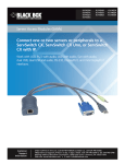
1
® ® NETWORK SERVICES KVTA170UK-16 KVTA171UK-16 KKVTA174UK-16 ServView CX Rack Tray Compact and easy access to up to sixteen server systems from a single rack slot. Combined screen, keyboard, mouse and sixteen port KVM switch all housed within a neat fold-up industry standard 1U rack slot. Customer Support Information Order toll-free in the U.S.: Call 877-877-BBOX (outside U.S. call 724-746-5500) FREE technical support 24 hours a day, 7 days a week: Call 724-746-5500 or fax 724-746-0746 Mailing address: Black Box Corporation, 1000 Park Drive, Lawrence, PA 15055-1018 Web site: www.blackbox.com • E-mail: info@ blackbox.com ServView CX Rack Tray Trademarks Used in this Manual Black Box and the Double Diamond logo are registered trademarks, and ServView is a trademark, of BB Technologies, Inc. Mac is a registered trademark of Apple Computer, Inc. Linux is registered trademark of Linus Torvalds. Windows is a registered trademark of Microsoft Corporation. NetWare is a registered trademark of Novell, Inc. Sun is a trademark of Sun Microsystems, Inc. Unix is a registered trademark of UNIX System Laboratories, Inc. BSD is a registered trademark of UUNet Technologies, Inc. Any other trademarks mentioned in this manual are acknowledged to be the property of the trademark owners. We‘re here to help! If you have any questions about your application or our products, contact Black Box Tech Support at 724-746-5500 or go to blackbox.com and click on “Talk to Black Box.” You’ll be live with one of our technical experts in less than 30 seconds. Page 2 724-746-5500 | blackbox.com FCC and IC RFI Statements Federal Communications Commission and Industry Canada Radio Frequency Interference Statements This equipment generates, uses, and can radiate radio-frequency energy, and if not installed and used properly, that is, in strict accordance with the manufacturer’s instructions, may cause interference to radio communication. It has been tested and found to comply with the limits for a Class A computing device in accordance with the specifications in Subpart B of Part 15 of FCC rules, which are designed to provide reasonable protection against such interference when the equipment is operated in a commercial environment. Operation of this equipment in a residential area is likely to cause interference, in which case the user at his own expense will be required to take whatever measures may be necessary to correct the interference. Changes or modifications not expressly approved by the party responsible for compliance could void the user’s authority to operate the equipment. This digital apparatus does not exceed the Class A limits for radio noise emission from digital apparatus set out in the Radio Interference Regulation of Industry Canada. Le présent appareil numérique n’émet pas de bruits radioélectriques dépassant les limites applicables aux appareils numériques de la classe A prescrites dans le Règlement sur le brouillage radioélectrique publié par Industrie Canada. 724-746-5500 | blackbox.com Page 3 ServView CX Rack Tray Instrucciones de Seguridad (Normas Oficiales Mexicanas Electrical Safety Statement) 1. T odas las instrucciones de seguridad y operación deberán ser leídas antes de que el aparato eléctrico sea operado. 2. Las instrucciones de seguridad y operación deberán ser guardadas para referencia futura. 3. Todas las advertencias en el aparato eléctrico y en sus instrucciones de operación deben ser respetadas. 4. Todas las instrucciones de operación y uso deben ser seguidas. 5. E l aparato eléctrico no deberá ser usado cerca del agua—por ejemplo, cerca de la tina de baño, lavabo, sótano mojado o cerca de una alberca, etc. 6. El aparato eléctrico debe ser usado únicamente con carritos o pedestales que sean recomendados por el fabricante. 7. El aparato eléctrico debe ser montado a la pared o al techo sólo como sea recomendado por el fabricante. 8. Servicio—El usuario no debe intentar dar servicio al equipo eléctrico más allá a lo descrito en las instrucciones de operación. Todo otro servicio deberá ser referido a personal de servicio calificado. 9. El aparato eléctrico debe ser situado de tal manera que su posición no interfiera su uso. La colocación del aparato eléctrico sobre una cama, sofá, alfombra o superficie similar puede bloquea la ventilación, no se debe colocar en libreros o gabinetes que impidan el flujo de aire por los orificios de ventilación. 10. El equipo eléctrico deber ser situado fuera del alcance de fuentes de calor como radiadores, registros de calor, estufas u otros aparatos (incluyendo amplificadores) que producen calor. 11. E l aparato eléctrico deberá ser connectado a una fuente de poder sólo del tipo descrito en el instructivo de operación, o como se indique en el aparato. 12. Precaución debe ser tomada de tal manera que la tierra fisica y la polarización del equipo no sea eliminada. 13. Los cables de la fuente de poder deben ser guiados de tal manera que no sean pisados ni pellizcados por objetos colocados sobre o contra ellos, poniendo particular atención a los contactos y receptáculos donde salen del aparato. 14. El equipo eléctrico debe ser limpiado únicamente de acuerdo a las recomendaciones del fabricante. 15. E n caso de existir, una antena externa deberá ser localizada lejos de las lineas de energia. 16. El cable de corriente deberá ser desconectado del cuando el equipo no sea usado por un largo periodo de tiempo. 17. Cuidado debe ser tomado de tal manera que objectos liquidos no sean derramados sobre la cubierta u orificios de ventilación. 18. Servicio por personal calificado deberá ser provisto cuando: A: El cable de poder o el contacto ha sido dañado; u B: Objectos han caído o líquido ha sido derramado dentro del aparato; o C: El aparato ha sido expuesto a la lluvia; o D: El aparato parece no operar normalmente o muestra un cambio en su desempeño; o E: El aparato ha sido tirado o su cubierta ha sido dañada. Page 4 724-746-5500 | blackbox.com Table of Contents Contents 1. Specifications............................................................................................................................................................................... 6 2. Introduction................................................................................................................................................................................ 7 2.1 What‘s Included................................................................................................................................................................. 8 2.2 Additional Items You May Need........................................................................................................................................ 9 3. Installation................................................................................................................................................................................. 10 3.1 Suitable mounting locations............................................................................................................................................. 10 3.2 Mounting the rack tray.................................................................................................................................................... 10 3.3 Connecting the rack tray..................................................................................................................................................12 3.3.1 The EXTernal link (network or remote user).........................................................................................................12 3.3.2 Server access module links ..................................................................................................................................13 3.4 Power Connection................................................................................................................................................. 14 4. Configuration.............................................................................................................................................................................15 4.1 Initial Configuration..........................................................................................................................................................15 5. Operation.................................................................................................................................................................................. 16 5.1 Opening and closing the rack tray.................................................................................................................................... 16 5.1.1 To open the rack tray........................................................................................................................................... 16 5.1.2 To close the rack tray............................................................................................................................................17 5.2 Operating the rack tray.................................................................................................................................................... 18 5.2.1 The screen controls............................................................................................................................................. 18 5.2.2 Using the OSD menu for the screen.................................................................................................................... 19 5.2.3 Selecting server channels.................................................................................................................................... 19 Appendix A. Safety Information.................................................................................................................................................... 20 Appendix B. Screen specifications................................................................................................................................................. 21 724-746-5500 | blackbox.com Page 5 ServView CX Rack Tray 1. Specifications Approvals: CE, FCC Software Compatibility: Operates with all known software and operating systems including Windows®, Linux®, Unix®, BSD, all Sun® OS, all Mac® OS, NetWare®, etc. Operating Temperature: 32 to 104°F (0 to 40°C) Power: Page 6 DC jack (power adapter included) Input: 100–240 VAC, 50/60 Hz Output: 12VDC, 60W 724-746-5500 | blackbox.com Chapter 2: Overview 2. Introduction Thank you for choosing the Black Box ServView CX Rack Tray which combines screen, keyboard, mouse and sixteen port KVM switching while occupying only a single rack slot. The screen and keyboard slide out to provide quick access to all systems when working in the server room. All models also facilitate either remote or global access for authorised users who are away from the server room. All KVM links to servers are made using Black Box Server Access Modules (SAMs) that attach to the rack tray rear panel via standard CATx cables. These make installation straightforward while ensuring that all cabling remains neat and uncluttered. See Figure 2-1. Carry handle to release the two-point lock Certain sections of this manual refer to other Black Box user guides for details about the KVM module fitted within your rack tray. These other guides are stored on the CD-ROM supplied with your rack tray and are also available at the Black Box website. Clear LCD display screen Display control panel Keyboard and mouse touchpad KVM switch with connections at the rear Reserved Switch for screen auto power off 16 INDOOR USE ONLY EXT 12V 5A 15 14 13 8 11 10 9 4 7 6 5 3 2 1 OPTIONS 1 2 ON 12 COMPUTER CONNECTIONS Power input socket Config switches Reserved for future use - ensure that both are in the up (off) position. Network or remote extender port Function is determined by the model of KVM module. The green indicator is on when power is applied. COMPUTER CONNECTIONS Computer Connection ports 16 ports to which CAT 5, 5e or 6 link cables are used to connect Server Access Modules (SAMs) which provide the connections to each server. Options port Used for firmware upgrades. The amber indicator is reserved for future use. Figure 2-1. The front and rear panels of the ServView CX Rack Tray. 724-746-5500 | blackbox.com Page 7 ServView CX Rack Tray 2.1 What‘s Included Your package should include the following items. If anything is missing or damaged, contact Black Box at 724-746-5500 or [email protected]. • ServView CX rack tray assembly • Left and right mounting brackets • 8 x screws and cup washers • 6 x cage nuts • Power adapter and power cord • CD-ROM containing this user manual in PDF format • Safety leaflet - Please carefully read this leaflet. Page 8 724-746-5500 | blackbox.com Chapter 2: Overview 2.2 Additional Items You May Need • Server Access Modules: PS/2-style - Analog video, PS/2-style keyboard and PS/2-style mouse. Part code: KV1400A. USB - Analog video, USB keyboard and mouse. Part code: KV1401A. Sun - Analog video, Sun keyboard and mouse plus 3.5mm audio jack. Part code: KV1404A. Console SAM - (for KVTA174UK-16 only) D-sub 9-way female. Part code: KV1407A. 724-746-5500 | blackbox.com Page 9 ServView CX Rack Tray 3. Installation 3.1 Suitable mounting locations • It is very important to locate the ServView CX Rack tray in a suitable environment. • The surface for placing and fixing the rack tray should be stable and level, or mounted into a suitable cabinet. • Make sure the place has good ventilation, is out of direct sunlight, away from sources of excessive dust, dirt, heat, water, moisture and vibration. • Position the rack tray with respect to related facilities. 3.2 Mounting the rack tray 1 Determine the appropriate position for the rack tray within your rack frame. Insert two of the supplied cage nuts in each of the rear vertical rack rails and one cage nut in the lower position of each front rack rail. See Figure 3-1. The unit is heavy. Therefore when installing, place the rack tray on a sturdy, level surface to prevent it from accidentally falling and causing damage to other equipment or injury to persons nearby. Figure 3-1. The mounting brackets. 2 Attach the supplied left and right mounting brackets to the positions in your rack frame where the cage nuts are located and adjust the bracket depths to suit the depth of the rack. For each mounting bracket: • Use two M6 screws and cup washers to fix the bracket to the rear rack rail. • Use one M6 screw and cup washer (only in the lower hole of the bracket) to fix the bracket to the front rack rail. Leave all screws loose until the rack tray assembly has been put into place. Page 10 724-746-5500 | blackbox.com Chapter 3: Installation 3 Insert the rack tray assembly into the mounting brackets. See Figure 3-2. Figure 3-2. Inserting the rack tray. 4 Pull and hold the left and right black arrow buttons on the rails. 5 Return the LCD keyboard drawer to park position. 6 Use the remaining two M6 screws and cup washers to fix the front mounting ears of the rack tray assembly to rack rails. See Figure 3-3. Figure 3-3. Securing the rack tray. 7 Tighten all eight M6 screws to complete the installation. 724-746-5500 | blackbox.com Page 11 ServView CX Rack Tray 3.3 Connecting the rack tray All server, network and power connections are located at the rear of the unit. 3.3.1 The EXTernal link (network or remote user) The single RJ-45 socket labeled as EXT is used to allow either global or remote users to login and control connected servers. The EXT port provides one of the following links (dependant on the model of rack tray): • An ethernet network link, labeled , or • A remote extender link (to attach a ServSwitch CX Remote USB), labeled KVM only . Note: This port is NOT a network port. 3.3.1.1 Connecting the external link 1 Wherever possible, ensure that power is disconnected from the rack tray. 2 Connect a CAT 5, 5e or 6 link cable to the port labeled EXT. See Figure 3-4. EX T Link cable from either a network connection or a remote extender Figure 3-4. Connecting a CAT 5, 5e or 6 link cable to the EXT port. 3 Connect the other end of the cable as follows: • If the EXT port label shows • If the EXT port label shows Page 12 connect the link cable to a network switch/router. KVM only connect the link cable to a Black Box ServSwitch CX Remote USB extender. 724-746-5500 | blackbox.com Chapter 3: Installation 3.3.2 Server access module links There are sixteen RJ-45 sockets labeled as COMPUTER CONNECTIONS on the rear panel. Each socket supports a CAT 5, 5e or 6 link to an individual server system. Note: The maximum length of the SAM cable can be up to 10 metres (32 feet). For model KVTA170UK-16, also ensure that the overall distance between a remote user (connected to a remote extender) and any SAM unit/server does not exceed 300 metres (980 feet). 1 Wherever possible, ensure that power is disconnected from the rack tray. 2 Connect a CAT 5, 5e or 6 link cable to one of the COMPUTER CONNECTIONS ports. See Figure 3-5. 8 7 6 5 4 CO MP 3 UT ER CO NN 2 EC T ION S 1 Link cable to a Server Access Module Figure 3-5. Connecting a SAM link cable. 3 Connect the other end of the cable to the Server Access Module (SAM) that is linked to the required server system. For more information about connecting SAMs, please refer to the appropriate Black Box user guide as appropriate to the rack tray model being used: • KVTA170UK-16 ---> use ServSwitch CX Uno user guide (KV0081A/KV0161A), • KVTA171UK-16 ---> use ServSwitch CX Uno IP user guide (KV1081A/KV1161A), • KVTA174UK-16 ---> use ServSwitch CX Quad IP user guide (KV4161A). 4 Repeat steps 2 and 3 for each server system. 724-746-5500 | blackbox.com Page 13 ServView CX Rack Tray 3.4 Power Connection The KVM module is provided with a power adapter capable of supplying the display monitor, keyboard and KVM module. IMPORTANT: You must only use the manufacturer approved power adapter with the KVM module. IMPORTANT: Due to the length of the power cable, if the rack tray is mounted high in the rack it may not be possible to place the power adapter at floor level. In this case it is important to mount it securely and in such a manner that it is not suspended from its output cable. 1 Attach the output lead from the power adapter to the 12V socket on the rear panel of the KVM module. See Figure 3-6. 12 V 5A 1 2 ON Figure 3-6. Connect the power adapter to the rear panel power socket. 2 Connect the IEC connector of the supplied country-specific power lead to the socket of the power adapter. 3 Connect the power cord to a nearby power outlet. Note: Both the KVM module and the power adapter generate heat when in operation and will become warm to the touch. Do not enclose them or place them in locations where air cannot circulate to cool the equipment. Do not operate the equipment in ambient temperatures exceeding 35oC. Do not place the products in contact with equipment whose surface temperature exceeds 35oC. 3.4.1 Disconnecting Power When removing the power connection be aware that the plug has a locking mechanism to prevent accidental disconnects. To remove, pull back the flat top segment of the plug body to disengage the lock and gently pull the whole plug from the power socket. See Figure 3-7. Figure 3-7. Disconnecting the power adapter. Page 14 724-746-5500 | blackbox.com Chapter 4: Configuration 4. Configuration 4.1 Initial Configuration The precise details for configuration of the KVM module will depend on the model being used. For more information, please refer to the Configuration section of the appropriate ServSwitch user guide as appropriate to the KVM module being used: • KVTA170UK-16 ---> use ServSwitch CX Uno user guide (KV0081A/KV0161A), • KVTA171UK-16 ---> use ServSwitch CX Uno IP user guide (KV1081A/KV1161A), • KVTA174UK-16 ---> use ServSwitch CX Quad IP user guide (KV4161A). 724-746-5500 | blackbox.com Page 15 ServView CX Rack Tray 5. Operation 5.1 Opening and closing the rack tray The compact rack tray is easy to open and close when required. 5.1.1 To open the rack tray 1 Press the button on the carry handle at the front of the rack tray unit and gently pull the carry handle towards you. See Figure 5-1. Figure 5-1. Press the release button and pull the rack tray. 2 Once the drawer is fully extended, lift up the carry handle to reveal the screen and keyboard. See Figure 5-2. Figure 5-2. Lift up the carry handle. Note for safe use • Keep all liquids away from the equipment to minimise the risk of accidental spillage. Liquid spilled on to the power supply or on other hardware may cause damage, fire or electrical shock. Page 16 724-746-5500 | blackbox.com Chapter 5: Operation 5.1.2 To close the rack tray 1 Fold down the screen and locate the black arrow release button on each side of the drawer slider. See Figure 5-3. Figure 5-3. Locate the release buttons on each side. 2 Pull forward and hold the two black arrow buttons while slightly pushing the drawer slider in to release the locks. 3 Gently push the drawer slider all the way into the rack using the carry handle. Take care to keep your fingers away from the sliders. See Figure 5-4. Figure 5-4. Be sure to keep your fingers away from the sliders. 724-746-5500 | blackbox.com Page 17 ServView CX Rack Tray 5.2 Operating the rack tray 5.2.1 The screen controls The screen controls are located at the base of the screen. See Figure 5-5. Figure 5-5. Screen controls. Power indicator. (green = on, orange = power saving mode). Page 18 Power button for the screen. Display the OSD menu for the screen. Scroll buttons to control OSD menus for the screen. (To auto adjust screen, press and hold for 5 seconds). Exit the screen OSD menu. (Also used to toggle digital DVI-D and analog SVGA inputs, where appropriate). 724-746-5500 | blackbox.com Chapter 5: Operation 5.2.2 Using the OSD menu for the screen Press the button to display the OSD menu for the screen: The various sections within the screen menu are as follows: Image Controls for brightness, contrast, colour temp, red, green and blue. Geometry Controls for auto adjust, H position, V position, phase and clock. Not used Not used Misc Controls for language, OSD position, graphic mode, OSD time, ratio, reset and timer. 5.2.3 Selecting server channels In operation, you can select server channels in two main ways, including: • On-screen menu (this is different to the OSD for the screen), or • Keyboard hotkeys. For more information, please refer to the Operation section of the appropriate Black Box user guide as appropriate to the rack tray model being used: • KVTA170UK-16 ---> use ServSwitch CX Uno user guide (KV0081A/KV0161A), • KVTA171UK-16 ---> use ServSwitch CX Uno IP user guide (KV1081A/KV1161A), • KVTA174UK-16 ---> use ServSwitch CX Quad IP user guide (KV4161A). The label above the keyboard provides useful reminders about how to select the on-screen menu and server channels: ServView CX Tray B L A C K 724-746-5500 | blackbox.com B O X R A C K T R A Y K V M S W I T C H Page 19 ServView CX Rack Tray Appendix A. Safety Information • For use in dry, oil free indoor environments only. • Unplug equipment before cleaning. Don’t use liquid or spray detergent; use a moist cloth. • The unit is heavy. Therefore when installing, place the rack tray on a sturdy, level surface to prevent it from accidentally falling and causing damage to other equipment or injury to persons nearby. • Both the rack tray and its power supply generate heat when in operation and will become warm to the touch. Do not enclose them or place them locations where air cannot circulate to cool the equipment. Do not operate the equipment in ambient temperatures exceeding 35º Celcius (95º Fahrenheit). Do not place the products in contact with equipment whose surface temperature exceeds 35º C (95º F). • Ensure that the power adaptor is mounted so that neither its cables nor connectors are stressed. • Observe all precautions and warnings attached to the equipment. • Warning - live parts contained within power adapter. • No user serviceable parts within power adapter - do not dismantle. • Plug the power adapter into a grounded socket outlet close to the rack tray. • Replace the power adapter with a manufacturer approved type only. • Do not use the power adapter if the power adapter case becomes damaged, cracked or broken or if you suspect that it is not operating properly. • Do not attempt to service the unit yourself. • Not suitable for use in hazardous or explosive environments or next to highly flammable materials. • If you use a power extension cord with a unit, make sure the total ampere rating of the devices plugged into the extension cord does not exceed the cord’s ampere rating. Also, make sure that the total ampere rating of all the devices plugged into the wall outlet does not exceed the wall outlet’s ampere rating. Page 20 724-746-5500 | blackbox.com Appendices Appendix B. Screen specifications The following specifications apply to both screen sizes unless indicated otherwise: Maximum resolution Brightness Contrast ratio Viewing angle Display area 1280x 1024 300 Cd/m2 1000:1 160o x 160o 338 x 270mm (17” model) or 376 x 301mm (19” model) 724-746-5500 | blackbox.com Page 21 Black Box Tech Support: FREE! Live. 24/7. Tech support the way it should be. Great tech support is just 30 seconds away at 724-746-5500 or blackbox.com. ® ® NETWORK SERVICES About Black Box Black Box Network Services is your source for an extensive range of networking and infrastructure products. You’ll find everything from cabinets and racks and power and surge protection products to media converters and Ethernet switches all supported by free, live 24/7 Tech support available in 30 seconds or less. © Copyright 2011. Black Box Corporation. All rights reserved. KVTA170UK series, rev. 1.0 724-746-5500 | blackbox.com