1
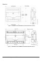
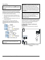
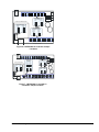
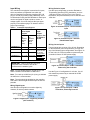
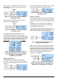
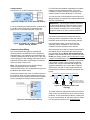
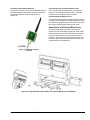
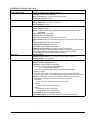
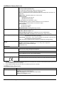
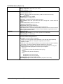
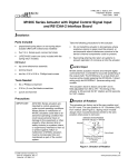
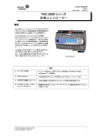
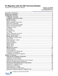
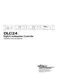
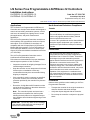
LN Series Free Programmable LN-PRGxxx-12 Controllers Installation Instructions Code No. LIT-12011796 LN-PRG203-12, LN-PRG300-12, LN-PRG4x0-12, LN-PRG6x0-12 Issued April 24, 2014 Supersedes January 30, 3013 Refer to the QuickLIT Web site for the most up-to-date version of this document. Applications North American Emissions Compliance The LN Series Free Programmable LN-PRGxxx-12 Controllers are microprocessor-based and designed to control various building automation systems, such as multi-zone air handing units, lighting control, central plant applications, and power measurement applications. Canada The LN Free Programmable Controllers are built on a similar platform, but have different numbers of inputs and outputs. The LN PRG6x0-12 controllers are compatible with the LN Input/Output (I/O) Extension Module 400 Series models. For more information on LN I/O Extension Modules, refer to LN Series Input/ Output (I/O) Extension Modules Installation Instructions (LIT-12011693). Industry Canada Statement The term IC before the certification/registration number only signifies that the Industry Canada technical specifications were met. Le terme « IC » précédant le numéro d'accréditation/ inscription signifie simplement que le produit est conforme aux spécifications techniques d'Industry Canada. United States This equipment has been tested and found to comply with the limits for a Class A digital device pursuant to Part 15 of the FCC Rules. These limits are designed to provide reasonable protection against harmful interference when this equipment is operated in a commercial environment. This equipment generates, uses, and can radiate radio frequency energy and, if not installed and used in accordance with the instruction manual, may cause harmful interference to radio communications. Operation of this equipment in a residential area may cause harmful interference, in which case the users will be required to correct the interference at their own expense. The LN Free Programmable Controllers use the LONWORKS® communication protocol. Follow these recommendations for proper installation and subsequent operation of each controller: • Inspect the controller for shipping damages. Do not install damaged controllers. • Keep the controller at room temperature for at least 24 hours prior to installation to allow any condensation that may have accumulated during shipping to evaporate. • If the controller is used in a manner not specified by Johnson Controls, the functionality and the protection provided by the controller may become impaired. Installation Record the 12-digit Neuron® ID located on either end of the device (shown on the sticker below the barcode) for commissioning. • Transport the controller in the original container to minimize vibration and shock damage. • Verify that all parts shipped with the controller. • Do not drop the controller or subject it to physical shock. • Note: The controller’s plastic enclosure has a back plate that is separate from the front plate allowing the back plates to be shipped directly to the installation site while all the engineering is done elsewhere. Observe these guidelines when installing an LN Free Programmable Controller: IMPORTANT: Prevent any static electric discharge to the controller. Static discharge can damage the controller and void the warranties. LN Series Free Programmable LN-PRGxxx-12 Controllers Installation Instructions 1 Dimensions Figure 1: LN-PRG203-12 and LN-PRG300-12 Controller Dimensions, mm (in.) Figure 2: LN-PRG4x0-12 and LN-PRG6x0-12 Controller Dimensions, mm (in.) 2 LN Series Free Programmable LN-PRGxxx-12 Controllers Installation Instructions Mounting Wiring Location Considerations Observe these guidelines when mounting an LN Free Programmable Controller: • Allow for proper clearance around the controller’s enclosure, wiring terminals, and service pin to provide easy access for hardware configuration and maintenance. • Ensure proper ventilation of each controller and avoid areas where corroding, deteriorating, or explosive vapors, fumes, or gases may be present. • Orient each controller with the ventilation slots and power supply/output terminal block connector towards the top to permit proper heat dissipation. • ! Do not mount the controller on surfaces prone to vibration, such as duct work, or in areas where electromagnetic emissions from other devices or wiring can interfere with controller communication. You can mount each controller on a DIN rail, on a wall, or in a panel. The controllers are equipped with two mounting holes 0.25 x 0.165 in. (6.35 x 4.191 mm). MISE EN GARDE : Risque de décharge électrique. Débrancher l'alimentation avant de réaliser tout raccordement électrique afin d'éviter tout risque de décharge électrique. Follow these wiring recommendations: • Remove the front plate from the back plate to facilitate in the wiring process. Use a small flat screwdriver to tighten the terminal connector screws once the wires are inserted. • Keep power cables apart from other types of wiring to avoid ambient noise transmission to other wires (for example, for power, 3-wire voltage, and current inputs and outputs). • Use wires or flat cables ranging from 22 to 14 AWG (0.644 to 1.630 mm diameter) per pole. Power cables must remain between 18 to 14 AWG (1.024 to 1.630 mm) diameter. • Do not connect the universal inputs, analog/digital outputs or common terminals to earth or chassis ground unless otherwise stated. • Keep all wires away from high speed data transmission cables (for example, Ethernet cable). • Keep input and output wires in conduits, trays, or close to the building frame whenever possible. DIN Rail To mount the controller on a DIN rail: 1. Ensure the DIN rail is properly mounted on the wall. 2. Clip the controller onto the DIN rail. Wall Mount To mount the controller on a wall: 1. Press on the side clips to separate the controller’s front and back plates. CAUTION: Risk of Electric Shock. Disconnect the power supply before making electrical connections to avoid electric shock. 2. Use the holes on the back plate to mark the wall location. 3. Drill the holes. Clean the surface and mount the controller using the appropriate screws. LN Series Free Programmable LN-PRGxxx-12 Controllers Installation Instructions 3 Power Wiring IMPORTANT: Voltage: 24 VAC/DC; +15%, Class 2. This is a Class 2 Product. Use a Class 2 transformer only (rated at 100 VA or less at 24 VAC) to power the controller. We recommend wiring only one controller per 24 VAC transformer. When only one transformer is available, determine the maximum number of controllers that can be supplied using the following method for calculating the required power transformer capacity: 1. Add up the maximum power consumption of all controllers, including external loads, and multiply this sum by 1.3. 2. If the resulting number is higher than 100 VA, use multiple transformers. Use an external fuse on the 24 VAC/DC side (secondary side) of the transformer to protect all controllers against power link spikes (Figure 3 and Figure 4). IMPORTANT: Connect the COM terminal of each controller and each peripheral to the same terminal on the secondary side of the transformer. One terminal on the secondary side of the transformer must be connected to the building’s ground. Failure to maintain consistent polarity throughout the entire network will result in a short circuit and damage to the controller. IMPORTANT: The COM terminals of the controller are internally wired to the 24 V COM terminal of the power supply. Connecting a peripheral or another controller to the same transformer without maintaining polarity between these devices will cause a short circuit. Note: Connecting the power source to an electrical system ground is not a requirement for proper system operation. However, it is a good installation practice in order to maintain the same potential between all controllers and Protective Earth. Configuration Jumper Location and Identification Controllers have the following onsite configurable jumpers. Figure 3: Power Wiring - DC Wireless Port Net to Subnet Settings Enabled Disabled* Figure 4: Power Wiring - AC IMPORTANT: Maintain consistent polarity when you connect the controllers and devices to the transformer. Subnet Port * Factory-default position Figure 5: LN-PRG203-12 Controller Jumper Locations 4 LN Series Free Programmable LN-PRGxxx-12 Controllers Installation Instructions Wireless Port Universal Outputs (UO) 0-10V / 0-20mA Select LONWORKS Network Board 0-10V* 0-20mA Net to Subnet Settings Enabled Disabled* Universal Inputs (UI) 0-20mA Enable / Disable 0-20mA 0-20mA Disable* Enable Subnet Port * Factory-default positions Figure 6: LN-PRG300-12 Controller Jumper Locations Wireless Port Typical locations: Quantity may vary according to controller model PRG6x0-12 ONLY: Subnetwork EOL Termination LONWORKS Network Board Universal Outputs (UO) 0-10V / 0-20mA Select 0-10V* 0-20mA EOL Off EOL On (Disabled)* (Enabled) Net to Subnet Settings Enabled Disabled* OR EOL Off EOL On (Disabled)* (Enabled) Universal Inputs (UI) 0-20mA Enable / Disable 0-20mA 0-20mA Disable* Enable Subnet Port * Factory-default positions Figure 7: LN-PRG4x0-12 and 6x0-12 Controller Jumper Location LN Series Free Programmable LN-PRGxxx-12 Controllers Installation Instructions 5 Heat A1 A2 4A Fuse Transformer Fast Acting To Return Fan Starter A1 A2 To Supply Fan Starter 0-10 VDC + ~ Cool - 0-10 VDC + ~ Damper Humidifier - 0-10 VDC + ~ - 0-10 VDC + ~ - 24VAC Electrical System Ground Service PIN Button LONWORKS® Mixed Air Temperature 10k? type II Return Fan State Digital contact Supply Fan State Digital contact Return Air Humidity 2-wire, 4-20mA Supply Air Humidity 2-wire, 4-20mA Return Air Temperature 10k? type II ON OFF EOL Supply Air Temperature 10k? type II * 249 ohmResistor built-in for inputs configured as 4-20mA Back of LN SVSENx To Next Device CT From Previous Device CT LONW ORKS Network * typ_power_connection EOL Enabled at the last sensor at the end of the Bus LN SVSENx Figure 8: Typical Power and Network Connections with an LN-SVSENx-0 Input 6 LN Series Free Programmable LN-PRGxxx-12 Controllers Installation Instructions Input Wiring Wiring Resistive Inputs The controllers have physical connections for inputs, which are software configurable from within the device’s Graphical Programming Interface (GPI) LN plug-in, the LN plug-in when using LN Builder, or the LN wizard when using the BSC Workbench. Each input can be configured for digital, resistive, current, or voltage signals. You must configure the input types properly in the software plug-in or wizard to ensure proper input readings. Use this input configuration to monitor Resistance Temperature Detectors (RTD); thermistors, such as 1,000 ohm RTDs to 10k ohm Type II and Type III thermistors; and potentiometers, such as 10k ohm and 100k ohm. Figure 10: Resistive Input – RTD/Thermistor Input Table 1: Controller Input Support Controller Fast and Slow Pulse Inputs support 50 Hz: 10 ms minimum ON/OFF (Fast Pulse) 1 Hz: 500 ms minimum ON/OFF (Slow Pulse) Current Input Jumper support: 0 to 10 VDC/0 to 20 mA Figure 11: Resistive Input – 10k ohm Potentiometer Input Wiring Current Inputs LN-PRG203-12 none Ul1 to Ul6 none LN-PRG300-12 Ul1 to Ul4 Ul5 to Ul10 LN-PRG4x0-12 Ul1 to Ul4 Ul5 to Ul12 LN-PRG6x0-12 Ul1 to Ul4 Ul5 to Ul16 yes; see Figure 16 and the section Configuration Jumper Location and Identification IMPORTANT: Before connecting any input equipment to the controller, refer to the manufacturer’s installation guide. Note: For wire length less than 75 feet (23 m), use either a shielded or unshielded 18 AWG wire. Note: For a wire up to 200 feet (61 m) long, a shielded 18 AWG wire is recommended. Current inputs have a range of 0 to 20 mA. Depending on the transducer power requirements, you may use any of the following input configurations. Use Figure 12 for the 2-wire, 0 to 20 mA transducer powered by the controller’s internal 15 VDC power supply. Figure 12: Current Input – 2-Wire Transducer Powered by the Controller Use the Figure 13 configuration for a 2-wire, 0 to 20 mA transducer powered by an external 24 AC/DC power supply. Note: The wire should be shielded on the controller side and the shield length should be kept as short as possible. Wiring Digital Inputs Use this input configuration to monitor digital dry contacts, as well as pulsed contacts. Figure 13: Current Input – 2-Wire Transducer, Externally Powered Figure 9: Digital Input – Digital Dry Contact (N.O. and N.C.) LN Series Free Programmable LN-PRGxxx-12 Controllers Installation Instructions 7 Use the Figure 14 configuration for a 3-wire, 0 to 20 mA transducer powered by an external 24 AC/DC power supply. Connect the voltage input according to Figure 18 if the transducer is powered by its own power source. Figure 18: Voltage Input – Transducer with Its Own Power Source Figure 14: Current Input – 3-Wire Transducer, Externally Powered Use the Figure 15 configuration for a transducer powered by its own power source. Wiring Pulse Inputs The input must be wired according to the requirements of the connected pulse meter (for example, fast pulse or slow pulse and internal or external supply type). See Table 1. Configure the Pulse Input Types in the software to verify the pulse meter is powered correctly (set the Internal/External Supply Type). Figure 15: Current Input – Transducer with Its Own Power Source Connect the pulse input according to Figure 19 for a pulse meter that can pull down a +5 VDC supply with a 10k ohm pull-up resistor (internal supply type). For the LN-PRG300-12, LN-PRG4x0-12, and LN-PRG6x0-12 controllers, it is not necessary to connect a 249 ohm resistor at the input as this resistor is built-in to the controller. For these models, configure the input jumper as follows. For jumper location, see Configuration Jumper Location and Identification. Figure 19: All Pulse Input Types – Internal Supply, 2-wire Pulse Meter Figure 16: Equivalent Circuit for 0 to 20 mA Current Input Showing the Jumper Setting for the LN-PRG300-12, LN-PRG4x0-12, and LN-PRG6x0-12 Controllers When you use a pulse meter that requires more than 5 VDC to operate, you must use a Fast Pulse Input type (Table 1). An external power supply is required to operate the pulse meter. You may use the controller’s built-in power supply as shown in Figure 20 or use an external power source (from 6 VDC to 27 VDC maximum — see Figure 21). Wiring Voltage Inputs Voltage inputs have a range of 0 to 10 VDC or 0 to 5 VDC. Connect the voltage input according to Figure 17 if you are using a 3-wire 0 to 10 V or 0 to 5 V transducer. Figure 20: Fast Pulse Input Type - External Supply, 2-wire Pulse Meter for LN-PRG300, LNPRG4x0-12, and LN-PRG6x0-12 Controllers Figure 17: Voltage Input – 3-Wire Transducer 8 LN Series Free Programmable LN-PRGxxx-12 Controllers Installation Instructions Patch cable fitted with connectors supplied by Johnson Controls are wired as T568B. For more information on network topology and length, cable type, setting the Subnet ID and more, refer to the LN Series Communicating Sensors Installation Instructions (LIT-12011795) and the LONWORKS LN-Series Network Communication and Interface Guide Technical Bulletin (LIT-12011253). Figure 21: Fast Pulse Input Type – External Supply, 2-wire Pulse Meter LN Series Communicating Sensors Wiring The LN Communicating Sensors (LN-SVSEN-0 and LN-SVSENH-0) are communicating room temperature sensors with backlit displays and graphical menus. Connect the LN-SVSENx-0 Sensor to the SUBNET PORT modular connector of the controller with a standard Category 5e Ethernet patch cable fitted with RJ-45 connectors. If you make your own patch cable, use category 5e crimped with RJ-45 connectors either T568A or T568B. IMPORTANT: Do not crimp one connector as T568A and the other connector as T568B on the same cable. T568A 1 2 3 4 5 6 7 8 Output Wiring Table 2: T568A and T568B Terminations for RJ-45 Connector Pin T568A (at both cable ends) T568A (at both cable ends) Pair Color Pair Color 1 3 white/green stripe 2 white/orange stripe 2 3 green solid 2 orange solid 3 2 white/orange stripe 3 white/green stripe 4 1 blue solid 1 blue solid 5 1 white/blue stripe 1 white/blue stripe 6 2 orange solid 3 green solid 7 4 white/brown stripe 4 white/brown stripe 8 4 brown solid 4 brown solid T568B Key: 1 2 3 4 5 6 7 8 Each controller has physical connections for digital (triac) or universal outputs, depending on type and model. These outputs are all software configurable. Table 3 shows the controller outputs. Table 3: Controller Output Support Stripe Solid Pair 3 Pair 1 Pair 2 Pair 4 Controller Pair 2 Pair 1 Pair 3 Pair 4 Figure 22: T568A and T568B Crimp Wire Sequence for an RJ-45 Connector Digital (Triac) Outputs Universal Outputs Jumper 0 to 10 VDC/0 to 20 mA LN-PRG203-12 5 3 no LN-PRG300-12 0 8 yes LN-PRG4x0-12 0 12 yes LN-PRG6x0-12 0 12 yes For jumper location, see Configuration Jumper Location and Identification. Note: Before you connect output equipment to the controller, refer to the installation instructions from the equipment manufacturer. Figure 23: Pins on RJ-45 Jack Face LN Series Free Programmable LN-PRGxxx-12 Controllers Installation Instructions 9 If a floating actuator is being controlled, connect the digital output according to Figure 26. Output Wiring Recommendations Output wiring recommendations include: • For a wire length less than 75 feet (23 m) long, use either a shielded or unshielded 18 AWG wire. • For a wire length up to 200 feet (61 m) long, use a shielded 18 AWG wire. • The shield of the wire should be grounded on the controller side and the shield length should be kept as short as possible. Actuator Cy DOy ~ Cx DOx 24VAC ~ Figure 26: Digital Triac Output – Floating Actuator Wiring Digital Outputs (DOx) Digital outputs are all made of triacs and there is not voltage present on the output terminals. Therefore, you must add an external power source, typically 24 VAC. Note: To measure the state of a triac output, an external load must be connected. If a 24 VAC relay is being controlled, connect it to a digital output according to Figure 24 or Figure 25, ensuring that the transformer’s secondary wiring is grounded as shown. Line Switching 24VAC 24VCOM AC Transformer 24VAC 24VCOM 24VAC A2 Load A1 AC Transformer Controller Electrical System Ground DOx Cx If a 12 VDC relay is being controlled, connect it to a universal output according to Figure 27. Fuse: 4A Max. Fast Acting 24VAC Controller Wiring Discrete Outputs Neutral Switching Fuse: 4A Max. Fast Acting Electrical System Ground DOx Cx A2 Load A1 24VAC Relay 24VAC Relay Figure 24: Digital Triac Output — Relay Using the Same Power Source as Controller Line Switching Neutral Switching 24VAC Relay DOx Cx A2 24VAC Relay Load A1 Fuse: 4A Max. Fast Acting 24VAC DOx Cx A2 Load A1 AC 24VAC Wiring Current Outputs The 0 to 20 mA signal is configurable by jumper (available for LN-PRG300-12, LN-PRG4x0-12, and LN-PRG6x0-12 only; for jumper location, see Configuration Jumper Location and Identification). AC Transformer Electrical System Ground Figure 25: Digital Triac Output, Line Switching – Relay Using an External Power Source 10 Figure 27: Discrete 0 or 12 VDC Universal Output – Relay Fuse: 4A Max . Fast Acting Transformer Electrical System Ground Wiring Universal Outputs (UOx) You can configure universal outputs to provide either a discrete signal of 0 or 12 VDC, a linear signal ranging from 0 to 10 VDC, or a 0 to 20 mA signal (LN-PRG300-12, LN-PRG4x0-12 and LN-PRG6x0-12 only). The discrete signal can be used to generate a pulse wave modulation (PWM) signal or a simple two-state signal. These outputs are protected by an auto-reset fuse. Figure 28: 0 to 20 mA Universal Output and Jumper Configuration LN Series Free Programmable LN-PRGxxx-12 Controllers Installation Instructions Voltage Outputs Connect the 0 to 10 VDC as shown in Figure 29. For information and detailed explanations on network topology and wire length restrictions, refer to the LONWORKS LN-Series Network Communication and Interface Guide Technical Bulletin (LIT-12011253). You can also refer to the Echelon® Junction Box and Wiring Guideline for Twisted Pair LONWORKS Networks (Part No. 005-0023-01). Figure 29: Voltage 0 to 10 VDC Universal Output If you are controlling an analog actuator, connect the 0 to 10 VDC output, along with an external 24 VAC power source, to the analog actuator (Figure 30). IMPORTANT: Use the proper network terminators for the network topology. Failure to use the correct network terminators may result in communication errors between controllers. Do not use multiple gauges of cable on the same communication bus. Selecting Network Terminators Two network terminators are required for the bus topology network configuration. Place one network terminator at each end of the bus topology channel. Figure 30: Voltage 0 to 10 VDC Universal Output - Analog Actuator Communications Wiring The recommended cable type for LONWORKS® communications is 22 AWG (0.65 mm), twisted pair, unshielded wire. The LONWORKS communication wire is polarity insensitive and can be laid out in a bus, star, or free topology. For loop topology, take special care to maintain the polarity when connecting the LONWORKS network to avoid a short circuit. Note: We recommend you use the bus topology network configuration for all LONWORKS communication wiring. This configuration allows you to troubleshoot the network easily. Connect both wires to the LON1 or LON2 terminals of the controller. When you insert multiple wires into the terminals, ensure you properly twist the wires together prior to inserting them into the terminal connectors. One network terminator is required for the free topology network configuration. You can put the network terminator anywhere on the channel. When used with an LN Series Communicating Sensor, the network can be accessed at the sensor’s audio plug port when the two Net to Subnet Port Settings jumpers inside the LN-PRG Series controller are set to Enable (for jumper location, see Configuration Jumper Location and Identification). This connects the main LONWORKS network to the LN-SVSENx-0 subnetwork Cat 5e cable to create a free topology LONWORKS network with maximum allowable total length of all segments combined to be no more than 1,600 feet (500 meters). The Cat 5e cable length may also be restricted by the maximum allowable subnetwork bus length. 22AWG (0.65mm) Unshielded Twisted Pair Network Cable Free-Topology Network Controller LN-Series Sensor Cat5e network cable: LN Series Sensor Subnetwork Bus and LONWORKS Network Figure 32: LONWORKS Network Free Topology Figure 31: Communications Wiring This setup mixes the cable gauge used for the network, which under rare conditions my cause communication problems. To help avoid these problems, carefully test for good communication on the entire network. If there are any network problems, see Troubleshooting. LN Series Free Programmable LN-PRGxxx-12 Controllers Installation Instructions 11 Subnetwork Communications Wiring with the LN-PRG6x0-12 Controller Supported Quantity of Sensors Per Controller The LN-PRGxxx-12 controllers support between 4 and 12 LN Communicating Sensors. See Table 4 for the maximum allowable sensors per controller. You must set the Subnet ID of all sensors within the address range listed in Table 4. Table 4: Number of LN Communicating Sensors Controller Models Support Controller Series Maximum Number of Sensors Subnet ID Address Range LN-PRG203-12 4 1–12 LN-PRG300-12 12 1–12 LN-PRG4x0-12 12 1–12 LN-PRG6x0-12 12 1–12 LN-IOE400 Series Extension Modules are connected to the Subnet- and Subnet+ terminals of the LN-PRG6x0-12 Series controller. For more information about network length, cable type, controller addressing, refer to the LONWORKS LN-Series Network Communication and Interface Guide Technical Bulletin (LIT-12011253). Also, for information and requirements to implement the subnetwork for LN Input/Output (I/O) Extension Module 400 series models, refer to the LN Series Input/Output (I/O) Extension Modules Installation Instructions (LIT-12011693). Regardless of the mounting method, the wireless receiver should be 16 inches (41 cm) or more away from the controller or any other network cables. Wall or Ceiling Mount with Double-Sided Tape To mount on a wall using double-sided tape, first apply the tape to the back of the receiver and then stick the receiver onto the desired wall or ceiling location. Wall or Ceiling Mount with Screws To mount the wireless receiver with screws: 1. Separate the front and back plates on the receiver to open it. 2. Use the mounting holes on the back plate to mark the wall or ceiling location. 3. Drill the holes. 4. Clean the holes, insert wall anchors, and fasten the back plate with the screws. Metal Enclosure Mount To mount onto a metal enclosure: 1. Affix the 1/2 inch NPT hub to the bottom of the Wireless Receiver. Ensure the cap of the NPT hub is undone. 2. Place the Wireless Receiver onto the metal enclosure and align the NPT hub to the hole. 3. Use the cap to tighten the Wireless Receiver onto the enclosure. Wireless Installation The LN PRG Series controller can receive input signals from wireless devices when connected to a wireless receiver and programmed with GPI software. Compatible wireless devices include temperature sensors, duct sensors, window and door contacts, and light switches. These devices are easy to install, and can be mounted on a wide range of building materials. For information on selecting mounting locations for the LN Series wireless option controllers, refer to the LN Series Wireless Solution Guide Technical Bulletin (LIT-12011628). Figure 33: Metal Enclosure Mount Mounting the Wireless Receiver There are three mounting options: on a wall or ceiling with double-sided tape, on a wall or ceiling with mounting screws, or on a metal enclosure using a 1/2-inch National Pipe Thread (NPT) hub. 12 LN Series Free Programmable LN-PRGxxx-12 Controllers Installation Instructions Connecting the Wireless Receiver Connecting to the Controller Wireless Port Connect the wireless receiver to the controller with the included telephone cable (4P4C modular connectors). Locate the telephone socket inside the device (Figure 34). The wireless-option controllers have a wireless port where you connect the telephone cable. Locate the wireless port on the bottom of the controller. Disconnecting the Wireless Port To disconnect the plugged-in telephone cable from the controller’s wireless port, pass a pointed object through the hole above the wireless port and press on the top of the connector while gently pulling out the cable. Strain Relief and Terminal Block Cover In certain jurisdictions, terminal block covers are required to meet local safety regulations. Strain reliefs and terminal block covers are available for controllers housed in large enclosures and are used to relieve tension on the wiring and conceal the controllers’ wire terminals. Strain reliefs and terminal block covers are optional and are sold separately. Figure 34: Telephone Socket Location Figure 35: Large Enclosure Strain Relief and Terminal Block Cover Installation LN Series Free Programmable LN-PRGxxx-12 Controllers Installation Instructions 13 Maintenance ! • CAUTION: Risk of Electric Shock. Disconnect the power supply before making any electrical connections to avoid electric shock. MISE EN GARDE : Risque de décharge électrique. Débrancher l'alimentation avant de réaliser tout raccordement électrique afin d'éviter tout risque de décharge électrique. Each controller requires minimal maintenance, but it is important to: • clean the outside of the front plate and the inside of the back plate with a dry cloth. verify the tension of all wires and cables each time you service the controller. Disposal The Waste Electrical and Electronic Equipment (WEEE) Directive sets regulations for the recycling and disposal of products. The WEEE 2002/96/EG Directive applies to stand-alone products that can function on their own and are not a part of another system or piece of equipment. For this reason, Johnson Controls® products are exempt from the WEEE Directive. Nevertheless, they are marked with the WEEE symbol, indicating the devices are not disposed with municipal waste. Dispose of products at the end of their useful life according to local regulations and the WEEE Directive. Troubleshooting Table 5 describes some troubleshooting scenarios. Table 5: Troubleshooting (Part 1 of 3) Problem Solution Controller is powered but does not turn on. Fuse Is Blown Disconnect power from the controller and check the fuse integrity. Reconnect power. Power Supply Polarity Verify that consistent polarity is maintained between all controllers and the transformer. Ensure that the COM terminal of each controller is connected to the same terminal on the secondary side of the transformer. See Figure 4 and Figure 3. Controller cannot communicate on the LONWORKS network. Absent or Incorrect Supply Voltage 1. Check power supply voltage between 24 VAC/DC ±15% and COM pins, and ensure that it is between acceptable limits. 2. Check for tripped fuse or circuit breaker. Overloaded Power Transformer Verify the transformer is powerful enough to supply all controllers. Network Not Wired Properly Check that the wire connections are correct. Absent or Incorrect Network Termination Check the network terminations. Controller communicates well over a short network but does not communicate on large network. Network Length Check that the total wire length does not exceed the specifications of the Junction Box and Wiring Guideline for Twisted Pair LONWORKS Networks. Wire Type Check that the wire type agrees with the specification of the LONWORKS LNSeries Network Communications and Interface Guide Technical Bulletin (LIT1201253) or Junction Box and Wiring Guideline for Twisted Pair LONWORKS Networks. Network Wiring Problem Check that the wire connections are correct. Absent or Incorrect Network Termination Check the termination(s). Incorrect or broken termination(s) make the communication integrity dependent upon a controller's position on the network. Extra Capacitance Ensure no extra capacitance is connected to the network other than the standard FTT circuit, and a maximum of a 3 meter stub (in bus topology). Number of Devices on Network Segment Exceeded The number of controllers on a channel should never exceed 64. Use a router or a repeater in accordance with LONWORKS LN-Series Network Communications and Interface Guide Technical Bulletin (LIT-1201253) or Junction Box and Wiring Guideline for Twisted Pair LONWORKS Networks. 14 LN Series Free Programmable LN-PRGxxx-12 Controllers Installation Instructions Table 5: Troubleshooting (Part 2 of 3) Problem Solution Network Traffic Query node statistic to check errors. Use a LONWORKS protocol analyzer to check network traffic. I/O Extension Module cannot communicate on the subnetwork Absent or incorrect supply voltage 1. Check power supply voltage between 24 VAC +15% and COM pins and ensure it is within acceptable limits. 2. Check for tripped fuse or circuit breaker. Overloaded Power Transformer Verify the transformer is powerful enough to supply all controllers. Network Not Wired Properly Check that the wire connections are correct. Absent or Incorrect Network Termination Check the network termination(s). Only the last LN-IOE4x0 must have the EOL termination set to ON. When one or more LN-SVSENx-0 sensors are connected to the controller, only the last LN-SVSENx-0 sensor must have its EOL termination set to ON. Refer to the LN Series I/O Extension Modules Installation Instructions (LIT-12011693). There is another controller with the same Subnet ID on the subnetwork. Each I/O Extension Module on the subnetwork must have a unique Subnet ID. Look at the Subnet ID DIP switch on the faceplate of each I/O Extension Module. Network length Check that the total wire length does not exceed the specifications of the LONWORKS LN-Series Network Communication and Interface Guide Technical Bulletin (LIT-12011253). Wire type Check that the total wire type agrees with the specification of the LONWORKS LN-Series Network Communication and Interface Guide Technical Bulletin (LIT-12011253). Hardware input is not reading the correct value. Input Wiring Problem Check that the wiring is correct according to this manual and according to the peripheral device's manufacturer. Open Circuit or Short Circuit Using a voltmeter, check the voltage on the input terminal. A short circuit has a 0 V value and an open circuit has a 5 V value. Configuration Problem Check the configuration of the input using the controller configuration plug-in or wizard. Refer to the online help for more information. Over Voltage or Over Current at an Input An over voltage or over current at one input can affect the reading of other inputs. Observe the allowed voltage/current range limits for all inputs. Hardware output is not operating correctly. Fuse has blown (auto reset fuse) Disconnect the power and outputs terminals. Then wait a few seconds to allow the auto-reset fuse to cool down. Check the power supply and the output wiring if necessary. Output Wiring Problem Check that the wiring is correct according to this manual and according to the peripheral device's manufacturer. Configuration Problem Using the controller configuration wizard (LN-GPI), check the configuration of the input. Refer to the controller's user guide for more information. 0 to 10 V Output, 24 VAC Powered Actuator is Not Moving Check the polarity of the 24 VAC power supply connected to the actuator while connected to the controller. Reverse the 24 VAC wire if necessary. Wireless devices not working correctly. Device not associated to controller Using the device configuration wizard, check the configuration of the input. Power discharge Recharge the device with light (if solar powered) or replace the battery. Ensure sufficient light intensity (200lx for 4 hours per day) Device too far from the Wireless Receiver Reposition the device to be within the range of the Wireless Receiver. For information on typical transmission ranges, refer to the LN Series Wireless Solution Technical Bulletin (LIT-12011628). Configuration Problem Check the configuration of the input using the device configuration plug-in or wizard. LN Series Free Programmable LN-PRGxxx-12 Controllers Installation Instructions 15 Table 5: Troubleshooting (Part 3 of 3) Problem Solution Rx/Tx LEDs Rx LED not Blinking Data is not being received from the LONWORKS data bus. Tx LED not Blinking Data is not being transmitted onto the LONWORKS data bus. Status LED Operation Table 6: Status LED Operation Guide – Normal Operation Operation Service Initialization: the device is starting up. One Fast Blink Fast Blink Continuous (150 ms On, 150 ms Off, Continuous) Firmware upgrade in is progress and the controller operation is temporarily unavailable. The new firmware is being loaded into memory and the process takes a few seconds. Do not interrupt power to the device during this time. The Status LED is Always OFF The controller is operating normally. Table 7: Status LED Operation Guide – Repeats every 2 seconds (highest priority first) Operation Service Long blink continuous The controller is not configured. Appropriate action: Commission the controller. (1s On, 1s Off, Continuous) Long Long Long Blink (800 ms On, 300 ms Off, 800 ms On, 300 ms Off, 800 ms Off) The controller is offline. Appropriate action: Set the controller online. Long Short Short Short Blink The controller is in bypass mode. Appropriate Action: Set the controller online Short Short Long Blink Poor-quality power; the device has browned-out: The voltage at the 24 VAC and 24 VCOM terminals has gone below the device’s acceptable limit during powerup. Fast Blink 12x Wink: The wink function identifies a device. For further information on the LN Series Communicating Sensors, refer to the LN Series Communicating Sensors Installation Instructions (LIT-12011795). For further information on the LN-IOE4x0 Series Extension Modules, refer to the LN Series Input/Output (I/O) Extension Modules Installation Instructions (LIT-12011693). 16 Repair Information If the LN Series Controller fails to operate within its specifications, replace the unit. For a replacement controller, contact the nearest Johnson Controls® representative. LN Series Free Programmable LN-PRGxxx-12 Controllers Installation Instructions Technical Specifications LN-PRG203-12 (Part 1 of 2) Product Code LN-PRG203-12 Power Requirements Voltage: 24 VAC/DC; ±15%, 50/60 Hz, Class 2 Protection: 2.0A user-replaceable fuse Power Consumption: 14 VA typical plus all output loads Maximum Consumption: 23 VA Environmental Operating Temperature: 0 to 50°C, (32 to 122°F) Storage Temperature: -40 to 70°C, (-40 to 158°F) Relative Humidity: 0 to 90% General Processor: STM32 (ARM Cortex™ M3) MCU, 32 bit Processor Speed: 68 MHz Memory: 384kB Nonvolatile Flash (applications), 1 MB Nonvolatile Flash (storage) 64 kB RAM Media Channel: TP/FT-10; 78 Kbps Communication: LonTalk® protocol Status Indicator: Green LED - power status and LON TX, Orange LED - service and LON RX Communication Jack: LON® mono audio jack LONMARK® Interoperability: Version 3.4 Device Class: SCC Generic #8500 LONMARK Functional Profile (pending): Input Objects: Open-Loop Sensor #1, Output Objects: Open - Loop Sensor #3, Node Object: #0, Real Time Clock: Real Time Keeper #3300, Scheduler: Scheduler #20020, Calendar: Calendar #20030, Programmable Device: Static Programmable Device #410, SCC Generic #8500 Enclosure Material: ABS type PA-765A Dimensions (with screws): 5.7 x 4.7 x 2.0 in. (144.8 x 119.4 x 50.8 mm) Shipping Weight: 0.97 lb (0.44 kg) Inputs Number of Inputs: 6 LN Series Communicating Sensors: 4 Input Types: universal software configurable Voltage: 0 to 10 VDC (40k ohm input impedance) 0 to 5 VDC (high input impedance) Current: 0 to 20 mA with 249 ohmexternal resistor (wired in parallel) Digital: dry contact Pulse: dry contact; 500 ms minimum On/Off Resistor Support: 0 to 350k ohms. All thermistor types that operate within this range are supported. The following temperature sensors are pre-configured: Thermistor: Type 2 and Type 3 10k ohm (10k ohm at 25°C [77°F]) Platinum: PT1000 1k ohm (1k ohm at 0°C [32°F]) Nickel: RTD Ni1000 (1k ohm at 0°C [32°F]) RTD Ni1000 (1k ohm at 21°C [69.8°F]) Input Resolution: 16-bit analog/digital converter Power Supply Output: 15 VDC; maximum 200 mA (6 inputs x 20 mA each) LN Series Free Programmable LN-PRGxxx-12 Controllers Installation Instructions 17 LN-PRG203-12 (Part 2 of 2) Outputs Digital (Triac) Outputs: 5 Universal Outputs: 3 Digital: 24 VAC Triac, digital (on/off), floating, or PWM; software configurable 0.5 A continuous 1.0 A at 15% duty cycle for a 10-minute period PWM control: adjustable period from 2 seconds to 65 seconds Floating control: requires two consecutive outputs minimum plus on/off: 500 milliseconds adjustable drive time period External power supply Universal: Linear (0-10 VDC) Digital (on/off), PWM, or floating (0 to 12 VDC); software configurable; built-in snubbing diode to protect against back EMF, for example when used with a 12 VDC relay. PWM control: adjustable period from 2 seconds to 65 seconds Floating control: minimum plus on/off: 500 ms adjustable drive time period 60 mA maximum at 12 VDC (60°C [140°F]) minimum resistance 200 ohms Auto reset fuse 60 mA at 60°C (140°F) 100 mA at 20°C (68°F) Output Resolution: 10-bit digital/analog converter Wireless Receiver1 Communication: EnOcean® Wireless standard Number of Wireless Inputs2: 24 Supported Wireless Receivers: LN-WMOD315-0 and LN-WMOD868-0 Telephone Cord Cable: Connector: 4P4C modular jack, Length: 6.5 ft (2 m) Electromagnetic Compatibility CE Emission: EN61000-6-3: 2007 Generic standards for residential, commercial, and light-industrial environments (pending). CE Immunity: EN61000-6-1: 2007; Generic standards for residential, commercial, and light-industrial environments (pending). FCC: This device complies with FCC rules part 15, subpart B, class B (pending) LN Series Communicating Sensor Communication: RS-485 Number of sensors per controller: up to 4, in daisy-chain configuration Cable: Cat 5e, 8 conductor twisted pair Connector: RJ-45 Agency Compliance United States: Under UL 916, Energy Management Equipment Material3: UL94-5VA Canada: Under UL 916, Energy Management Equipment Material3: UL94-5VA Europe: CE Mark – Johnson Controls, Inc., declares that the products are in compliance with the essential requirements and other relevant provisions of the EMC Directive 2004/108/EC. 1. 2. 3. 18 Available when an optional external Wireless Receiver is connected to the controller. Some wireless inputs may use more than one wireless input from the controller. Some wireless modules may use more than one wireless input from the controller. All materials and manufacturing processes comply with the RoHS directive and are marked according to the Waste Electrical and Electronic Equipment (WEEE) directive. LN Series Free Programmable LN-PRGxxx-12 Controllers Installation Instructions LN-PRG300-12 (Part 1 of 2) Product Code LN-PRG300-12 Power Requirements Voltage: 24 VAC/DC; ±15%, 50/60 Hz, Class 2 Protection: 3.0 A user-replaceable fuse Power Consumption: 16 VA typical plus all output loads Maximum Consumption: 38 VA Environmental Operating Temperature: 0 to 50°C, (32 to 122°F) Storage Temperature: -20 to 50°C, (-4 to 122°F) Relative Humidity: 0 to 90% General Processor: STM32 (ARM Cortex™ M3) MCU, 32 bit Processor Speed: 72 MHz Memory: 1 MB Nonvolatile Flash (applications), 2 MB Nonvolatile Flash (storage) 96 kB RAM Media Channel: TP/FT-10; 78 Kbps Communication: LonTalk® protocol Transceiver: FT 5000 Free Topology Smart Transceiver Status Indicator: Green LED - power status and LON TX, Orange LED - service and LON RX Communication Jack: LON® mono audio jack LONMARK® Interoperability: Version 3.4 Device Class: Static Programmable Device LONMARK Functional Profile (pending): Input Objects: Open-Loop Sensor #1, Output Objects: Open - Loop Sensor #3, Node Object: #0, Real Time Clock: Real Time Keeper #3300, Scheduler: Scheduler #20020, Calendar: Calendar #20030, Programmable Device: Static Programmable Device #410 Enclosure Material: FR/ABS Dimensions (with screws): 5.7 x 4.7 x 2.0 in. (144.8 x 119.4 x 50.8 mm) Shipping Weight: 0.97 lb (0.44 kg) Inputs Number of Inputs: 10 LN Series Communicating Sensors: 12 Input Types: universal software configurable Voltage: 0 to 10 VDC (40k ohm input impedance) 0 to 5 VDC (high input impedance) Current: 0 to 20 mA with 249 ohmjumper configurable internal resistor Digital: dry contact Pulse: UI1 to UI4; 50 Hz maximum; Minimum 10 ms On/10 ms Off, SO output compatible; UI5 to UI10: 1 Hz maximum; Minimum 500 ms On/500 ms Off, dry contact Resistor Support: 0 to 350k ohms. All thermistor types that operate within this range are supported. The following temperature sensors are pre-configured: Thermistor: Type 2 and Type 3 10k ohm (10k ohm at 25°C [77°F]) Platinum: PT1000 1k ohm (1k ohm at 0°C [32°F]) Nickel: RTD Ni1000 (1k ohm at 0°C [32°F]) RTD Ni1000 (1k ohm at 21°C [69.8°F]) Input Resolution: 16-bit analog/digital converter Power Supply Output: 15 VDC; maximum 200 mA (10 inputs x 20 mA each) LN Series Free Programmable LN-PRGxxx-12 Controllers Installation Instructions 19 LN-PRG300-12 (Part 2 of 2) Outputs Universal Outputs: 8 Universal Output Characteristics: 0-10 VDC linear; digital 0 to12 VDC (on/off), PWM, or floating (0 to 12 VDC) 0 to 20 mA (jumper configurable); software configurable. Built-in snubbing diode to protect against back EMF, for example when used with a 12 VDC relay. PWM control: adjustable period from 2 to 65 sec Floating control: minimum plus on/off: 500 ms adjustable drive time period 60 mA maximum at 12 VDC (60°C; 140°F) Load Resistance: minimum resistance 200 ohms for 0 to 10 VDC and 0 to 12 VDC outputs, maximum 500 ohm for 0 to 20 mA output Auto reset fuse 60 mA at 60°C (140°F) 100 mA at 20°C (68°F) Output Resolution: 10-bit digital/does analog converter Wireless Receiver1 Communication: EnOcean® Wireless standard Number of Wireless Inputs2: 28 Supported Wireless Receivers: LN-WMOD315-0 and LN-WMOD868-0 Telephone Cord Cable: Connector: 4P4C modular jack, Length: 6.5 ft (2 m) Electromagnetic Compatibility CE Emission: EN61000-6-3: 2007 Generic standards for residential, commercial, and light-industrial environments (pending). CE Immunity: EN61000-6-1: 2007; Generic standards for residential, commercial, and light-industrial environments (pending). LN Series Communicating Sensor Communication: RS-485 Number of sensors per controller: up to 12, in daisy-chain configuration Cable: Cat 5e, 8 conductor twisted pair Connector: RJ-45 Compliance: United States UL Listed, File E107041, CCN PAZX7, Under UL 916, Energy Management Equipment FCC Compliant to CFR 47, Part 15, Subpart B, Class A Canada UL Listed, File E107041, CCN PAZX7, Under CAN/CSA C22.2 No. 205, Signal Equipment Industry Canada, ICES-003 Europe 1. 2. 20 CE Mark – Johnson Controls, Inc., declares that the products are in compliance with the essential requirements and other relevant provisions of the EMC Directive 2004/108/EC. Available when an optional external Wireless Receiver is connected to the controller. Some wireless inputs may use more than one wireless input from the controller. Some wireless modules may use more than one wireless input from the controller. LN Series Free Programmable LN-PRGxxx-12 Controllers Installation Instructions LN-PRG4x0-12 Series (Part 1 of 2) Product Code LN-PRG400-12, LN-PRG410-12 Power Requirements Voltage: 24 VAC/DC; ±15%, 50/60 Hz, Class 2 Protection: 3.0A user-replaceable fuse Power Consumption: 22 VA typical plus all output loads Maximum Consumption: 60 VA Environmental Operating Temperature: 0 to 50°C, (32 to 122°F) Storage Temperature: -20 to 50°C, (-4 to 122°F) Relative Humidity: 0 to 90% General Processor: STM32 (ARM Cortex™ M3) MCU, 32 bit Processor Speed: 72 MHz Memory: 1 MB Nonvolatile Flash (applications), 2 MB Nonvolatile Flash (storage) 96 kB RAM Media Channel: TP/FT-10; 78 Kbps Communication: LonTalk® protocol Transceiver: FT 5000 Free Topology Smart Transceiver Status Indicator: Green LED - power status and LON TX, Orange LED - service and LON RX Communication Jack: LON® mono audio jack LONMARK® Interoperability: Version 3.4 Device Class: Static Programmable Device LONMARK Functional Profile: Input Objects: Open-Loop Sensor #1, Output Objects: Open - Loop Sensor #3, Node Object: #0, Real Time Clock: Real Time Keeper #3300, Scheduler: Scheduler #20020, Calendar: Calendar #20030, Programmable Device: Static Programmable Device #410 Enclosure Material: FR/ABS Dimensions (with screws): 5.7 x 4.7 x 2.0 in. (144.8 x 119.4 x 50.8 mm) Shipping Weight: 0.97 lb (0.44 kg) Inputs Number of Inputs: 12 LN Series Communicating Sensors: 12 Input Types: universal software configurable Voltage: 0 to 10 VDC (40k ohm input impedance) 0 to 5 VDC (high input impedance) Current: 0 to 20 mA with 249 ohmjumper configurable internal resistor Digital: dry contact Pulse: UI1 to UI4; 50 Hz maximum; Minimum 10 ms On/10 ms Off, SO output compatible; UI5 to UI12: 1 Hz maximum; Minimum 500 ms On/500 ms Off, dry contact Resistor: 0 to 350k ohms. All thermistor types that operate within this range are supported. The following temperature sensors are pre-configured: Thermistor: Type 2 and Type 3 10k ohm (10k ohm at 25°C [77°F]) Platinum: PT1000 1k ohm (1k ohm at 0°C [32°F]) Nickel: RTD Ni1000 (1k ohm at 0°C [32°F]) RTD Ni1000 (1k ohm at 21°C [69.8°F]) Input Resolution: 16-bit analog/digital converter Power Supply Output: 15 VDC; maximum 200 mA (16 inputs x 20 mA each) LN Series Free Programmable LN-PRGxxx-12 Controllers Installation Instructions 21 LN-PRG4x0-12 Series (Part 2 of 2) Outputs Universal Outputs: 12 Universal Output Characteristics: 0-10 VDC linear; digital (on/off), PWM, or floating (0 to12 VDC) 0 to 20 mA (jumper configurable); software configurable. Built-in snubbing diode to protect against back EMF, for example when used with a 12 VDC relay. PWM control: adjustable period from 2 to 65 seconds Floating control: minimum plus on/off: 500 ms adjustable drive time period 60 mA maximum at 12 VDC (60°C; 140°F) Load Resistance: minimum resistance 200 ohms for 0 to 10 VDC and 0 to 12 VDC, maximum 500 ohm for 0 to 20 mA output Auto reset fuse 60 mA at 60°C (140°F) 100 mA at 20°C (68°F) Output Resolution: 10-bit digital/analog converter Wireless Receiver1 Communication: EnOcean® Wireless standard Number of Wireless Inputs2: 28 Supported Wireless Receivers: LN-WMOD315-0 and LN-WMOD868-0 Telephone Cord Cable: Connector: 4P4C modular jack, Length: 6.5 ft (2 m) Electromagnetic Compatibility CE Emission: EN61000-6-3: 2007 Generic standards for residential, commercial, and light-industrial environments (pending). CE Immunity: EN61000-6-1: 2007; Generic standards for residential, commercial, and light-industrial environments (pending). FCC: This device complies with FCC rules part 15, subpart B, class B (pending) LN Series Communicating Sensor Communication: RS-485 Number of sensors per controller: up to 12, in daisy-chain configuration Cable: Cat 5e, 8 conductor twisted pair Connector: RJ-45 Compliance: United States UL Listed, File E107041, CCN PAZX, Under UL 916, Energy Management Equipment FCC Compliant to CFR 47, Part 15, Subpart B, Class A Canada UL Listed, File E107041, CCN PAZX7, Under CAN/CSA C22.2 No. 205, Signal Equipment Industry Canada, ICES-003 Europe 1. 2. CE Mark – Johnson Controls, Inc., declares that the products are in compliance with the essential requirements and other relevant provisions of the EMC Directive 2004/108/EC. Available when an optional external Wireless Receiver is connected to the controller. Some wireless inputs may use more than one wireless input from the controller. Some wireless modules may use more than one wireless input from the controller. LN-PRG6x0 Series (Part 1 of 3) Product Code LN-PRG600-12, LN-PRG610-12 Power Requirement Voltage: 24 VAC/DC; ±15%, 50/60 Hz, Class 2 Protection: 3.0 A user-replaceable fuse Power Consumption: 22 VA typical plus all output loads Maximum Consumption: 65 VA 22 LN Series Free Programmable LN-PRGxxx-12 Controllers Installation Instructions LN-PRG6x0 Series (Part 2 of 3) Environmental Operating Temperature: 0 to 50°C, (32 to 122°F) Storage Temperature: -20 to 50°C, (-4 to 122°F) Relative Humidity: 0 to 90% General Processor: STM32 (ARM Cortex™ M3) MCU, 32 bit Processor Speed: 72 MHz Memory: 1 MB Nonvolatile Flash (applications), 2 MB Nonvolatile Flash (storage) 96 kB RAM Media Channel: TP/FT-10; 78 Kbps Communication: LonTalk® protocol Transceiver: FT 5000 Free Topology Smart Transceiver Status Indicator: Green LED - power status and LAN TX, Orange LED - controller status and LAN RX Communication Jack: LON® mono audio jack LONMARK® Interoperability: Version 3.4 Device Class: Static Programmable Device LONMARK Functional Profile: Input Objects: Open-Loop Sensor #1, Output Objects: Open - Loop Sensor #3, Node Object: #0, Real Time Clock: Real Time Keeper #3300, Scheduler: Scheduler #20020, Calendar: Calendar #20030, Programmable Device: Static Programmable Device #410 Enclosure Material: FR/ABS Dimensions (with screws): 5.7 x 4.7 x 2.0 in. (144.8 x 119.4 x 50.8 mm) Shipping Weight: 1.17 lb (0.53 kg) Inputs Number of Inputs: 16 LN Series Communicating Sensors: 12 Input Types: universal software configurable Voltage: 0 to 10 VDC (40k ohm input impedance), 0 to 5 VDC (high input impedance) Current: 0 to 20 mA with 249 ohmjumper configurable internal resistor Digital: dry contact Pulse: UI1 to UI4; 50 Hz maximum; Minimum 10 ms On/10 ms Off, SO output compatible; UI5 to UI16: 1 Hz maximum; Minimum 500 ms On/500 ms Off, dry contact Resistor Support: 0 to 350k ohms. All thermistor types that operate within this range are supported. The following temperature sensors are pre-configured: Thermistor: Type 2 and Type 3 10k ohm (10k ohm at 25°C [77°F]) Platinum: PT1000 1k ohm (1k ohm at 0°C [32°F]) Nickel: RTD Ni1000 (1k ohm at 0°C [32°F]) RTD Ni1000 (1k ohm at 21°C [69.8°F]) Input Resolution: 16-bit analog/digital converter Power Supply Output: 15 VDC; maximum 320 mA (16 inputs x 20 mA each) LN Series Free Programmable LN-PRGxxx-12 Controllers Installation Instructions 23 LN-PRG6x0 Series (Part 3 of 3) Outputs Number of Outputs: 12 Universal Output Characteristics: 0-10 VDC linear; digital 0 to12 VDC (on/off), PWM, or floating (0 to 12 VDC), 0 to 20 mA (jumper configurable); software configurable Built-in snubbing diode to protect against back EMF, for example when used with a 12 VDC relay. PWM control: adjustable period from 2 to 65 seconds Floating control: minimum plus on/off: 500 ms, adjustable drive time period HOA: Hand-Off-Auto-Switch (when equipped) Hand position potentiometer range: 0-12.5 VDC 60 mA maximum at 12 VDC (60°C; 140°F) Load Resistance: minimum resistance 200 ohms for 0 to 10 VDC and 0 to 12.5 VDC, maximum 500 ohm for 0 to 20 mA output Auto reset fuse 60 mA at 60°C (140°F), 100 mA at 20°C (68°F) Output Resolution: 10-bit digital/does analog converter Wireless Receiver1 Communication: EnOcean® Wireless standard Number of Wireless Input2s: 28 Supported Wireless Receivers: LN-WMOD315-0 and LN-WMOD868-0 Telephone Cord Cable: Connector: 4P4C modular jack, Length: 6.5 ft (2 m) Electromagnetic Compatibility CE Emission: EN61000-6-3: 2007 Generic standards for residential, commercial, and lightindustrial environments (pending). CE Immunity: EN61000-6-1: 2007; Generic standards for residential, commercial, and lightindustrial environments (pending). LN Series Communicating Sensor Communication: RS-485 Number of sensors per controller: up to 12, in daisy-chain configuration Cable: Cat 5e, 8 conductor twisted pair Connector: RJ-45 I/O Extension Modules (LN-IOE 400 Series) Communication: RS-485 Number of I/O Extension Modules per controller: up to 2, in daisy-chain configuration Compliance UL Listed, File E107041, CCN PAZX, Under UL 916, Energy Management Equipment United States FCC Compliant to CFR 47, Part 15, Subpart B, Class A Canada UL Listed, File E107041, CCN PAZX7, Under CAN/CSA C22.2 No. 205, Signal Equipment Industry Canada, ICES-003 Europe 1. 2. CE Mark – Johnson Controls, Inc., declares that the products are in compliance with the essential requirements and other relevant provisions of the EMC Directive 2004/108/EC. Available when an optional external Wireless Receiver is connected to the controller. Some wireless inputs may use more than one wireless input from the controller. Some wireless modules may use more than one wireless input from the controller. The performance specifications are nominal and conform to acceptable industry standard. For application at conditions beyond these specifications, consult the local Johnson Controls® office. Johnson Controls, Inc. shall not be liable for damages resulting from misapplication or misuse of its products. Building Efficiency 507 E. Michigan Street, Milwaukee, WI 53202 Metasys® and Johnson Controls® are registered trademarks of Johnson Controls, Inc. All other marks herein are the marks of their respective owners. © 2014 Johnson Controls, Inc. LN Series Free Programmable LN-PRGxxx-12 Controllers Installation Instructions Published in U.S.A. 24 www.johnsoncontrols.com