1
AUTO REF/KERATO/TONOMETER
Model
OPERATOR’S MANUAL
NIDEK CO., LTD.
(Manufacturer)
: 34-14, Maehama, Hiroishi-cho, Gamagori, Aichi 443-0038, Japan
Telephone: (81-533) 67-6611
Facsimile: (81-533) 67-6610
NIDEK CO., LTD
: 3F Sumitomo Fudosan Hongo Bldg., 3-22-5, Hongo,
(Tokyo Office)
Bunkyo-Ku, Tokyo 113-0033, Japan
Telephone: (81-3) 5844-2641
Facsimile: (81-3) 5844-2642
NIDEK INCORPORATED
: 47651 Westinghouse Drive, Fremont, California 94539, U. S. A.
(United States Agent)
Telephone: (510) 226-5700
Facsimile: (510) 226-5750
NIDEK SOCIETE ANONYME
: Europarc 13, rue Auguste Perret, 94042 CRETEIL, France
(EU Authorized Representative) Telephone: (01) 49 80 97 97
Facsimile: (01) 49 80 32 08
August 2007
15601-P902B
Printed in JAPAN
:
Use this device properly and safely.
BEFORE USE, READ THIS MANUAL.
This operator’s manual contains information necessary for the operation of the NIDEK
AUTO REF/KERATO/TONOMETER Model TONOREF II. This manual includes the
operating procedures, safety precautions, and specifications.
This manual is necessary for proper use. Especially, the safety precautions and operating
procedures must be thoroughly understood prior to operation of the device.
Keep this manual handy to verify use whenever necessary.
The device complies with ISO 10342 (Ophthalmic instruments-Eye Refractometers). The
dioptric powers are indicated with reference wavelength λd = 587.56 nm.
There are no user-serviceable parts inside the device except printer paper.
If you encounter any problems or have questions about the device, please contact NIDEK
or your authorized distributor.
"CAUTION! Federal Law (US) restricts this device to sale by or on the order of a physician or
a properly licensed practitioner."
Safety precautions
In this manual, signal words are used to designate the degree or level of safety alerting. The definitions are as follows.
WARNING • Indicates a potentially hazardous situation which, if not avoided, could result in death or
serious injury.
CAUTION
• Indicates a potentially hazardous situation which, if not avoided, may result in minor or
moderate injury or property damage accident.
Even situations indicated by “ CAUTION” may result in serious injury under certain conditions.
Safety precautions must be strictly followed at all times.
I
:
Use precautions
Before Use
CAUTION • Do not use the device for other than the intended purpose.
NIDEK is not responsible for accidents or malfunctions caused by misuse.
• Be sure to read the manual prior to operation of the device to understand the safety
precautions and operating procedures thoroughly.
Using the device for purposes other than specified in this manual may cause unexpected malfunctions and/or adverse events.
• Never modify nor touch the internal structure of the device.
Electric shock or malfunction may result.
• Install the device in an environment that meets the following conditions. The following
conditions must be maintained during use.
Use conditions
Temperature: +10 to +35°C
Humidity: 30 to 75% (Non-condensing)
Pressure: 800 to 1060 hPa
A dust-free location
A place with little external light
A level and stable surface free from vibration and shock
If the device is not installed and used under the above conditions, the reliability of measured results is impaired, and malfunction may result. In addition, there is a possibility of
injury if the device receives shock and falls down.
• Install the device in an environment where no contaminants such as corrosive gas,
acid, and salt are contained in the air.
Corrosion or malfunction of the device may result.
• Avoid installing the device where it is exposed to direct air-conditioning flow.
Changes in temperature may result in condensation inside the device or adversely
affect measurements.
• Be sure to use a wall outlet which meets the power specification requirements.
If the line voltage is too high or too low, the device may not perform properly. Malfunction or fire may occur.
• Connect the power plug to a ground outlet. Or connect a grounding wire to a ground
terminal.
Electric shock or fire may occur in the event of device malfunction or power leakage.
• Completely insert the power plug into the outlet as far as the prongs will go.
Fire may occur if the device is used with a loose connection.
• Never use a table tap or extension cable to supply the device with power.
The electrical safety may be lowered.
II
:
CAUTION • Do not use a power cord other than the one supplied. Also do not connect the
supplied power cord to any other device.
Failure or fire may result.
• Do not place heavy objects on the power cord.
The damaged power cord may cause fire or electric shock.
• Before connecting cables to the device, turn the device off and disconnect the power
cord from an outlet.
Malfunction may result.
• Before carrying the device, put the device into the packing mode and lock the main
body to the base with the locking lever.
An accidental movement of the measuring unit during transportation may result in malfunction.
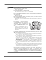
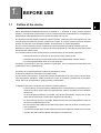
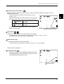
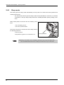
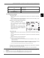
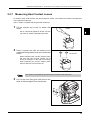
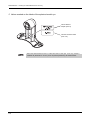
• When the device is carried, two persons
should hold (A) and (B) (both right and left
sides). Avoid holding the forehead rest
and the main body; hold the bottom of the
base.
If only one person carries the device, or
areas other than the base are held and
the device falls, there is a fear of injury or
malfunction.
(A)
(B)
• In installation and operation of the device, observe the following instructions about
EMC (electromagnetic compatibility):
- Do not use the device simultaneously with other electronic equipment to avoid electromagnetic interference with the operation of the device.
- Do not use the device near, on, or under other electronic equipment to avoid electromagnetic interference with the operation of the device.
- Do not use the device in the same room with other equipment such as life-support
equipment, other equipment that has major affects on the life of the patient and
results of treatment, or other measurement or treatment equipment that involves
small electric current.
- Do not use the device simultaneously with portable and mobile radio frequency communication systems because it may have an adverse effect on operation of the
device.
- Do not use cables and accessories that are not specified for the device because that
may increase the emission of electromagnetic waves from the device or the system
and decrease the immunity of the device to electromagnetic disturbance.
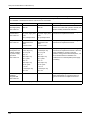
• The Electromagnetic Compatibility Directive sets the essential requirements for
electrical and electronic equipment that may disturb, or be disturbed by, other
equipment. The TONOREF II complies with these requirements as tabled on pages 121
to 124. Follow the guidance in the tables for use of the device in an electromagnetic
environment.
III
:
During Use
WARNING • Before starting NT measurement, set the safety stopper for each patient to prevent the
air nozzle from touching the patient’s eye.
Contact between the air nozzle and the eye may damage the cornea.
CAUTION • Before
use, perform visual and operation checks. If abnormal conditions are
encountered, stop using the device.
If the device is used under abnormal conditions, intended results may not occur. Also
unexpected malfunctions or health hazards may occur due to improper measurement.
• Be sure to connect an interface cable, checking the symbols of input (IN:
output (OUT:
) and
).
Data transmission may not be performed properly.
• Take care not to catch hands or fingers in moving parts (measurement part and chin
rest). Be sure to give this caution to patients.
Hands or fingers may be pinched and may result in injury.
• When measuring, caution patients not to touch the NT measurement part.
When switching from NT measurement to R/K measurement, the air nozzle recesses
and the shutter closes at which time fingers may be caught in the shutter. (In this case,
the cover stops immediately and does not result in injury.)
• Every time before treating a different patient, clean the patient’s contact area (chin
rest and forehead rest) using disinfectant alcohol.
If chinrest paper is used, remove one piece for each patient.
• Keep the measuring window free of fingerprints and dust.
The measurement accuracy may decrease substantially.
• In the event of smoke or strange odors, immediately turn off the device and
disconnect the power plug from the outlet. After you are sure that the smoke has
stopped, then contact NIDEK or your authorized distributor.
Usage of the device under such abnormal conditions may cause fire or electric shock.
In case of fire, use a dry chemical (ABC) extinguisher to extinguish the fire.
• Immediately replace the power cord if the internal wires are exposed, the device turns
on or off when the power cord is moved, or the cord and/or plug are too hot to be held
with hands.
This may result in electric shock or fire.
In the event of malfunction, disconnect the power cord from the wall outlet. Never touch
the inside of the device and contact NIDEK or your authorized distributor.
• Never press the LCD display with a hard object such as a ball-point pen. Keep
magnetic objects away from the LCD display.
The device may be damaged.
• Do not operate the LCD display with wet hands.
Water seeping into the device may result in failure of the device.
IV
:
CAUTION • There may be a few constantly-lit, missing, or dead pixels in your LCD which are a
characteristic of the LCD. This does not represent failure of the LCD; continuously
use the display.
• This device has been tested and found to comply with the limits for medical devices
to the IEC 60601-1-2: 2001, and Medical Device Directive 93/42/EEC.
These limits are designed to provide reasonable protection against harmful
interference in a standard medical installation.
This device generates, uses and can radiate radio frequency energy and, if not
installed and used in accordance with the instructions, may cause harmful
interference to other devices in the vicinity.
However, there is no guarantee that interference will not occur in a particular
installation. If this device does cause harmful interference to other devices, which can
be determined by turning the device off and on, the user is encouraged to try to
correct the interference by one or more of the following measures:
If this device does cause harmful interference to other devices, which can be
determined by turning the device off and on, the user is encouraged to try to correct
the interference by one or more of the following measures:
Reorient or relocate the receiving device.
Increase the separation between the devices.
Connect the device to an outlet on a circuit different from that to which the other
device(s) are connected.
Consult the manufacturer or field service technician for help.
• The device is Class A (CISPR11 classification). It is allowed in domestic
establishments when used under jurisdiction of a health care professional.
• Never use the device with cables or accessories other than the designated ones.
Malfunction caused by improper electromagnetic compatibility (EMC) characteristics
may result.
• Never use portable or mobile radio frequency (RF) devices in the vicinity of this
device.
These devices may adversely affect medical electrical equipment and malfunction may
result.
• The device uses thermal paper for printer. When saving the printings, make a copy of
it.
Thermal paper may become difficult to read due to aged deterioration.
• This device uses a heat-sensitive printer paper. To keep the printed data for a long
period of time, make copies of the printouts.
The paper degrades over time and the printed data may become illegible.
V
:
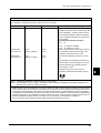
CAUTION • Information
on the avoidance of overexposure to potentially hazardous optical
radiation (ISO 15004: 1997)
Spectrally weighted photochemical radiances LB and LA give a measure of the potential
that exists for a beam of light to cause photochemical hazard to the retina. LB gives the
measure for eyes in which the crystalline lens is in place. LA gives this measure either
for eyes in which the crystalline lens has been removed (aphakes) and has not been
replaced by a UV-blocking lens or for the eyes of very young children.
The value stated for this ophthalmic device gives a measure of hazard potential when
the device is operated at maximum intensity and maximum aperture. The values of LA
or LB for the TONOREF II are sufficiently low as shown on the following page.
The retinal exposure dose for a photochemical hazard is a product of the radiance and
the exposure time. For instance, at a radiance level of 0.5 mW/(cm2zsr), 480 min irradiation of the dilated (8 mm diameter) pupil would cause the retinal exposure dose level to
attain the recommended exposure limit. If the value of radiance were reduced to 0.1
mW/(cm2zsr), five times that time (i.e. 2400 min) would be needed to reach the recommended limit. The recommended exposure dose is based on calculations arising from
the American Conference of Governmental Industrial Hygienists (ACGIH) - Threshold
Limit Values for Chemical Substances and Physical Agents (1995 - 1996 edition).
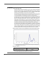
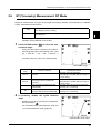
The following page shows the graph of spectrum output for the TONOREF II. Patients will
be at low risk of acute optical radiation with the TONOREF II. However, it is recommended
that the intensity of light directed into the patient’s eye be limited to the minimum level
which is necessary for diagnosis. The total of the retinal exposure dose must be carefully
watched for infants, aphakes and persons with diseased eyes who are at greater risk
when other ophthalmic devices with a high level of radiance are used in conjunction.
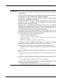
Irradiance (μW/cm2 )
• Spectrum output of all light source during AR/KM measurement (maximum light intensity)
Wavelength (nm)
* The wavelength 1000 to 1100 is calculated and plotted according to the wavelength characteristic data of the infrared LED used.
• Spectrum irradiance
LA (mW/cm2/sr) 305 - 700 nm
0.0027
LB (mW/cm2/sr) 380 - 700 nm
0.0003
LA: Spectrally weighted photochemical aphakic source radiance
LB: Spectrally weighted photochemical phakic source radiance
VI
:
After Use
CAUTION • When the device is not in use, turn off the power switch and put the dust cover over
the device.
If not, dust may affect the measurement accuracy.
• Do not yank the power cord to disconnect it from a wall outlet but hold the plug.
This can damage the metal core of the cord and may result in fire, short circuit or electric shock.
• Occasionally clean the prongs of the main plug with a dry cloth.
If dust settles between the prongs, the dust will collect moisture, and short circuit or fire
may occur.
• If the device will not be used for a long time, disconnect the power cord from the wall
outlet.
Fire may occur.
• Maintain the surrounding temperature and humidity at the following ranges during
transportation and storage of the device.
Environmental conditions:
Temperature: –10ºC to +55ºC
Humidity: 10 to 95% (non-condensing)
Pressure: 700 hPa to 1060 hPa
No large amount of dust is contained in the air.
A place not exposed to direct sunlight
• To transport the device, use the special packing materials to protect from shock and
impact.
Excessive vibration or impact may cause device malfunction.
• When transporting, set the mode to Packing mode and pack the main body in the
original packing material with the fixing lever unlocked.
It may result in failure when excessive vibration and shock are applied.
VII
:
Maintenance
CAUTION • Only service technicians properly trained by NIDEK can repair the device.
NIDEK is not responsible for any accidents resulted from improper servicing.
• When performing maintenance work, secure sufficient maintenance space.
Maintenance work in an insufficient space may result in injury.
• When the device is sent back to NIDEK for repair or maintenance, wipe the surfaces
(especially, the area where patients contact) of the device with a clean cloth
dampened with ethyl alcohol for disinfection.
• Contact NIDEK or your authorized distributor to check whether the device needs
measurement accuracy calibration if the AR-measured results are substantially
different from subjectively measured results.
• To maintain the performance, ask NIDEK to conduct yearly inspection.
Inspection items: Calibration of measurement value
Equipment component operation check
Disposal
CAUTION • Follow
local governing ordinances and recycling plans regarding disposal or
recycling of device components. The device contains the circuit board with a lithium
battery mounted. Because the disposal method of lithium batteries varies according
to the local government, follow the local governing ordinates and recycling plans
when disposing of the circuit board with the lithium battery.
It is recommended to commission the disposal to a designated industrial waste disposal
contractor.
• When disposing of packing materials, sort them by material and follow local
governing ordinances and recycling plans.
VIII
:
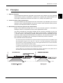
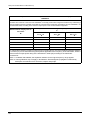
{ Patient environment
The patient environment represents a space where there is a possibility of direct contact between the
patient or the operator and third person.
When another type of device is used in the patient environment, use a device that complies with IEC
60601-1. If the devices that do not comply with IEC 60601-1 are used, it is necessary to use an isolating transformer as a power supply or to connect the devices to additional protective grounding.
Radius of 1.5 m
2.5 m
1.5 m
1.5 m
IX
Table of Contents
1. BEFORE USE . . . . . . . . . . . . . . . . . . . . . . . . . . . . . . . . . . . 1
1.1 Outline of the device . . . . . . . . . . . . . . . . . . . . . . . . . . . . . . . . . . . . . . . . . . . . . . . . . . . .1
1.2 Indications for Use . . . . . . . . . . . . . . . . . . . . . . . . . . . . . . . . . . . . . . . . . . . . . . . . . . . . .2
1.3 Principles . . . . . . . . . . . . . . . . . . . . . . . . . . . . . . . . . . . . . . . . . . . . . . . . . . . . . . . . . . . . . .3
1.4 Device Description . . . . . . . . . . . . . . . . . . . . . . . . . . . . . . . . . . . . . . . . . . . . . . . . . . . . .4
1.5 Measurement Screen Description . . . . . . . . . . . . . . . . . . . . . . . . . . . . . . . . . . . . . . .9
1.5.1
1.5.2
R/K measurement screen . . . . . . . . . . . . . . . . . . . . . . . . . . . . . . . . . . . . . . . . . . . . .9
NT measurement screen . . . . . . . . . . . . . . . . . . . . . . . . . . . . . . . . . . . . . . . . . . . .14
1.6 Labels and Indications on the Device . . . . . . . . . . . . . . . . . . . . . . . . . . . . . . . . . . .16
1.7 Checking Contents . . . . . . . . . . . . . . . . . . . . . . . . . . . . . . . . . . . . . . . . . . . . . . . . . . . .18
1.8 Before First Use . . . . . . . . . . . . . . . . . . . . . . . . . . . . . . . . . . . . . . . . . . . . . . . . . . . . . . .19
2. OPERATING PROCEDURES . . . . . . . . . . . . . . . . . . . . . . 23
2.1 Operation Flow . . . . . . . . . . . . . . . . . . . . . . . . . . . . . . . . . . . . . . . . . . . . . . . . . . . . . . . .23
2.2 Preparation for Measurement . . . . . . . . . . . . . . . . . . . . . . . . . . . . . . . . . . . . . . . . . .24
2.2.1
2.2.2
Measuring window check for soiling and puffed air pressure check during startup 29
Switching between R/K measurement and NT measurement . . . . . . . . . . . . . . . .31
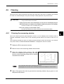
2.3 Finishing the Measurements . . . . . . . . . . . . . . . . . . . . . . . . . . . . . . . . . . . . . . . . . . .33
2.3.1
2.3.2
Normal shutoff. . . . . . . . . . . . . . . . . . . . . . . . . . . . . . . . . . . . . . . . . . . . . . . . . . . . .33
Shutoff before transporting the device . . . . . . . . . . . . . . . . . . . . . . . . . . . . . . . . . .33
2.4 Selecting the Mode . . . . . . . . . . . . . . . . . . . . . . . . . . . . . . . . . . . . . . . . . . . . . . . . . . . .35
2.4.1
2.4.2
Switching to manual mode . . . . . . . . . . . . . . . . . . . . . . . . . . . . . . . . . . . . . . . . . . .37
Sleep mode. . . . . . . . . . . . . . . . . . . . . . . . . . . . . . . . . . . . . . . . . . . . . . . . . . . . . . .38
2.5 AR (refractive error) and KM (corneal curvature radius) Measurements . . .39
2.5.1
2.5.2
2.5.3
2.5.4
2.5.5
2.5.6
2.5.7
AR (refractive error) and KM (corneal curvature radius) measurements:
AR/KM measurement mode . . . . . . . . . . . . . . . . . . . . . . . . . . . . . . . . . . . . . . . . . .39
AR (refractive error) Measurement: AR Measurement Mode . . . . . . . . . . . . . . . . .49
KM (corneal curvature radius) Measurement:
KM Measurement Mode . . . . . . . . . . . . . . . . . . . . . . . . . . . . . . . . . . . . . . . . . . . . .51
CS (Corneal Size) Measurement . . . . . . . . . . . . . . . . . . . . . . . . . . . . . . . . . . . . . .53
PS (Pupil Size) Measurement. . . . . . . . . . . . . . . . . . . . . . . . . . . . . . . . . . . . . . . . .55
PD (Pupillary Distance) Measurement . . . . . . . . . . . . . . . . . . . . . . . . . . . . . . . . . .57
Measuring Hard Contact Lenses . . . . . . . . . . . . . . . . . . . . . . . . . . . . . . . . . . . . . .59
2.6 NT (Tonometry) Measurement: NT Mode . . . . . . . . . . . . . . . . . . . . . . . . . . . . . . .61
2.6.1
Eyelid detection mode. . . . . . . . . . . . . . . . . . . . . . . . . . . . . . . . . . . . . . . . . . . . . . .70
2.7 Printing . . . . . . . . . . . . . . . . . . . . . . . . . . . . . . . . . . . . . . . . . . . . . . . . . . . . . . . . . . . . . . .71
2.7.1
2.7.2
2.7.3
X
Printing measured data. . . . . . . . . . . . . . . . . . . . . . . . . . . . . . . . . . . . . . . . . . . . . .71
Eyeprint. . . . . . . . . . . . . . . . . . . . . . . . . . . . . . . . . . . . . . . . . . . . . . . . . . . . . . . . . .74
Printing parameter settings . . . . . . . . . . . . . . . . . . . . . . . . . . . . . . . . . . . . . . . . . . .75
:
2.8 Parameter Settings . . . . . . . . . . . . . . . . . . . . . . . . . . . . . . . . . . . . . . . . . . . . . . . . . . . . 76
2.8.1
2.8.2
2.8.3
Parameter tables . . . . . . . . . . . . . . . . . . . . . . . . . . . . . . . . . . . . . . . . . . . . . . . . . . 79
Setting the date and time . . . . . . . . . . . . . . . . . . . . . . . . . . . . . . . . . . . . . . . . . . . . 89
Entering comments. . . . . . . . . . . . . . . . . . . . . . . . . . . . . . . . . . . . . . . . . . . . . . . . . 91
3. OPERATION WHEN PERIPHERAL DEVICES ARE
CONNECTED . . . . . . . . . . . . . . . . . . . . . . . . . . . . . . . . . . 93
3.1 Connecting to the NIDEK Motorized Refractor (RT) or Computer . . . . . . . . . 93
3.1.1
3.1.2
3.1.3
Outline . . . . . . . . . . . . . . . . . . . . . . . . . . . . . . . . . . . . . . . . . . . . . . . . . . . . . . . . . . 93
Connecting procedure . . . . . . . . . . . . . . . . . . . . . . . . . . . . . . . . . . . . . . . . . . . . . . 94
Operating procedure. . . . . . . . . . . . . . . . . . . . . . . . . . . . . . . . . . . . . . . . . . . . . . . . 94
3.2 Connecting to the NIDEK Auto Lensmeter (LM) . . . . . . . . . . . . . . . . . . . . . . . . . 95
3.2.1
3.2.2
3.2.3
Outline . . . . . . . . . . . . . . . . . . . . . . . . . . . . . . . . . . . . . . . . . . . . . . . . . . . . . . . . . . 95
Connecting procedure . . . . . . . . . . . . . . . . . . . . . . . . . . . . . . . . . . . . . . . . . . . . . . 95
Operating procedure. . . . . . . . . . . . . . . . . . . . . . . . . . . . . . . . . . . . . . . . . . . . . . . . 96
3.3 Connecting to the Eye Care Card System. . . . . . . . . . . . . . . . . . . . . . . . . . . . . . . 97
3.3.1
3.3.2
3.3.3
3.3.4
Outline . . . . . . . . . . . . . . . . . . . . . . . . . . . . . . . . . . . . . . . . . . . . . . . . . . . . . . . . . . 97
Method of connection . . . . . . . . . . . . . . . . . . . . . . . . . . . . . . . . . . . . . . . . . . . . . . . 97
Transferring data with the EyeCa-RW . . . . . . . . . . . . . . . . . . . . . . . . . . . . . . . . . . 98
Erasing data on the Eye Care card . . . . . . . . . . . . . . . . . . . . . . . . . . . . . . . . . . . . 99
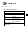
4. MAINTENANCE . . . . . . . . . . . . . . . . . . . . . . . . . . . . . . . 101
4.1 Troubleshooting . . . . . . . . . . . . . . . . . . . . . . . . . . . . . . . . . . . . . . . . . . . . . . . . . . . . . . 101
4.2 Error Messages and Countermeasures . . . . . . . . . . . . . . . . . . . . . . . . . . . . . . . . 103
4.3 Replacing Printer Paper . . . . . . . . . . . . . . . . . . . . . . . . . . . . . . . . . . . . . . . . . . . . . . 106
4.4 Fixing Chinrest Paper . . . . . . . . . . . . . . . . . . . . . . . . . . . . . . . . . . . . . . . . . . . . . . . . 108
4.5 Checking the AR/KM Measurement Accuracy . . . . . . . . . . . . . . . . . . . . . . . . . . 109
4.6 Cleaning . . . . . . . . . . . . . . . . . . . . . . . . . . . . . . . . . . . . . . . . . . . . . . . . . . . . . . . . . . . . . 111
4.6.1
4.6.2
4.6.3
Cleaning the measuring window. . . . . . . . . . . . . . . . . . . . . . . . . . . . . . . . . . . . . . 111
Cleaning the air nozzle . . . . . . . . . . . . . . . . . . . . . . . . . . . . . . . . . . . . . . . . . . . . . 113
Cleaning the printer . . . . . . . . . . . . . . . . . . . . . . . . . . . . . . . . . . . . . . . . . . . . . . . 114
4.7 List of Replacement Parts . . . . . . . . . . . . . . . . . . . . . . . . . . . . . . . . . . . . . . . . . . . . 114
5. SPECIFICATIONS AND ACCESSORIES . . . . . . . . . . . 115
5.1 Classifications . . . . . . . . . . . . . . . . . . . . . . . . . . . . . . . . . . . . . . . . . . . . . . . . . . . . . . . 115
5.2 Safety Features . . . . . . . . . . . . . . . . . . . . . . . . . . . . . . . . . . . . . . . . . . . . . . . . . . . . . . 116
5.3 Specifications . . . . . . . . . . . . . . . . . . . . . . . . . . . . . . . . . . . . . . . . . . . . . . . . . . . . . . . . 117
XI
:
5.4 Standard Configuration . . . . . . . . . . . . . . . . . . . . . . . . . . . . . . . . . . . . . . . . . . . . . . . 120
5.4.1
5.4.2
Standard accessories . . . . . . . . . . . . . . . . . . . . . . . . . . . . . . . . . . . . . . . . . . . . . . 120
Optional accessories . . . . . . . . . . . . . . . . . . . . . . . . . . . . . . . . . . . . . . . . . . . . . . 120
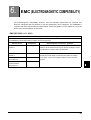
6. EMC (ELECTROMAGNETIC COMPATIBILITY) . . . . . . 121
7. GLOSSARY . . . . . . . . . . . . . . . . . . . . . . . . . . . . . . . . . . 125
8. INDEX . . . . . . . . . . . . . . . . . . . . . . . . . . . . . . . . . . . . . . . 129
XII
1.
1.1
BEFORE USE
Outline of the device
1
AUTO REF/KERATO/TONOMETER Model TONOREF II is designed to singly perform objective
refraction, corneal shape measurement, and non-contact tonometry measurement by incorporating a
standard auto ref/keratometer and non-contact tonometer into one unit.
The objective refraction function measures spherical powers, cylindrical powers and cylinder axis. The
corneal shape measurement function measures the radius of corneal curvature (corneal refractive
powers), the direction of the steepest meridian, and the amount of corneal astigmatism.
The non-contact tonometry function measures the intraocular pressure without contacting the eye.
Refraction is mainly performed as a reference for lens prescription for correction of visual acuity using
spectacles and contact lenses.
The corneal curvature radius measurement is performed mainly for the following purposes:
• To prescribe lenses for correction of visual acuity using contact lenses
• To determine the power of intraocular lenses to be implanted after cataract surgery
• To conduct postoperative follow-up of corneal shape
Tonometry is performed for the early detection of glaucoma, and for preoperative examination and
postoperative care in ophthalmology.
This device is an integral type with a main body mounted on a base.
A chinrest is mounted on the base on the patient’s side.
An LCD panel, control buttons, joystick and a printer are attached on the main body to conduct alignment and perform operations. Inside the device are units for performing AR/KM and NT measurements, which can be operated by simply pressing a button/switch.
In addition to the above, the device also offers the following features:
• A space-saving concept that allows AR/KM and NT measurements to be performed by a
single device which saves space and eliminates the need for the patient to move between
two devices.
• An auto-tracking mechanism is provided. The device automatically controls the up-anddown and back-and-forth movements for alignment and focusing.
• An auto-shooting function is provided. Measurements take place automatically when the
device is best aligned and in focus.
• An APC function that measures the intraocular pressure with the minimum necessary pressure of puffed air.
• A motorized up-and-down chinrest allows the operator to adjust the height of the chinrest.
• A built-in RS-232C interface allows data export to computers etc.
1
BEFORE USE: Indications for Use
1.2
Indications for Use
The AUTO REF/KERATO/TONOMETER TONOREF II is a medical apparatus which performs measurement of the refractive errors of the eye, corneal radius of curvature and intraocular pressure.
2
BEFORE USE: Principles
1.3
Principles
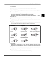
1. Objective refraction
Fine measurement beams are projected on the fundus of the patient’s eye by a projecting
optical system and then computation is performed by capturing the reflected beams as a
ring image to measure the refractive errors (SPH, CYL, AXIS) of the patient’s eye.
2. Corneal curvature radius measurement
Four near-infrared rays area projected onto the cornea and the ray reflected by the cornea is
detected. From the detected signals, the corneal curvature radius (refractive power) and the
direction of the steepest meridian are measured.
3. Measurement of intraocular pressure (NT measurement)
Based on the Imbert-Fick principle (W = Pt × A), the intraocular pressure is calculated by
dividing the amount of air pressure into the area of applanated surface.
The device increases the air pressure puffed onto the cornea in proportion to time. The
shape of the cornea changes gradually in the order of convex surface → applanated surface
→ concave surface. This change is optically detected and the device calculates the time
required to make the pressed area flat after air is puffed on it. The air pressure used to make
the cornea flat is calculated by time, and finally the intraocular pressure is obtained.
APC (Automatic Puff Control) function
The intraocular pressure measurement is performed with the air pressure as low as possible. When
the measurement range is set to “APC 40” or “APC 60”, in the first measurement, the automatic
shut-off function, which stops puffing air as soon as the light reflected from the cornea is detected,
activates in order to eliminate excessive puffing.
In subsequent measurements, the APC function activates to perform the measurement with the
minimum air pressure based on the former measurement data.
As the patient's eye is protected from excessive air pressure, discomfort of the patient can be
decreased and continuous measurement can be performed smoothly.
3
1
BEFORE USE: Device Description
1.4
Device Description
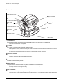
{ Front view
Function buttons
LCD screen
Memory indicator
Start button
Joystick
Locking lever
Power switch
Cover open button
Printer cover
Function buttons
Used to set the device and to switch the screen.
Functions assigned to the function buttons are displayed by icon next to each switch on the screen.
Lower two buttons on the left of the screen have unique functions when the measurement screen is displayed.
4
BEFORE USE: Device Description
• CLR button (
)
Used to clear the measured data.
When the CLR button is pressed for about a second, all the measured data is erased.
• Print button (
)
When this button is pressed while the memory indicator is lit, measured results are printed out.
If this button is pressed when the memory indicator is turned off, the printer paper is fed.
1
LCD screen
5.7-inch color LCD screen. The LCD screen panel pops out when the lower
portion of the panel is pulled toward you.
When operating the device in an upright position, tilt the panel so that the
indications on the screen are clear.
The panel is reset to its original position by magnet.
Memory indicator
Indicates that measured data is being stored in memory.
ON
Measured data is stored in the internal memory.
OFF
Measured data is not stored in the internal memory.
Blinking
Sleep mode
Start button
When the start button is pressed, the measurement takes place regardless of the alignment and focusing
status of the device.
Joystick
Used for alignment and focusing.
Tilt the joystick to the right and left for alignment. Turn the joystick for alignment in the up and down directions. For
focusing, push the joystick forward and pull it backward.
Locking lever
Used to fix the main body to the base unit.
To lock the main body, press the locking lever down.
Power switch
Used to turn on or off the power to the device.
Printer cover
Inside is the printer equipped with the auto cutter located. Open the printer cover for replacing printer paper
by pressing the cover open button.
Cover open button
To open the printer cover, press the button.
5
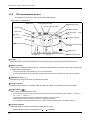
BEFORE USE: Device Description
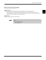
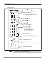
{ Rear view
Eyelid detection LEDs
Eye level marker
Forehead rest
LED for Corneal Illumination
Air nozzle
Measuring window
Chinrest up/down
buttons
Safety stopper
Chinrest
Patient sensor
PD window
Forehead rest
During measurements, the patient’s forehead should be gently placed over the forehead rest.
Clean the forehead rest for each patient.
Air nozzle
Air is puffed out of the nozzle of the NT measuring unit.
In this operator’s manual, the area containing the observation window around the air nozzle is referred to as the air
nozzle.
Just before the AR/KM measurement, the air nozzle is automatically stored in the device.
Measuring window
Performs R/K measurement.
Check the window for soiling before R/K measurement.
Chinrest
Clean the chinrest for each patient.
Patient sensor
The patient sensor detects whether the patient is seated in front of the device.
The sensor, while detecting the patient, assumes that the patient’s chin is placed on the chinrest. The chinrest is not
moved up and down to the origin for safety.
Eye level marker
Used as a guide for the patient's eye level during measurements.
The height of the chinrest should be adjusted so that the center level of the patient’s eye almost aligns with this line.
6
BEFORE USE: Device Description
Chinrest up/down buttons (
,
)
Move up or down the chinrest.
Safety stopper
Used to provide a safety space so that the air nozzle does not touch the patient’s eye.
1
Change the position of the stopper for each patient to keep the proper amount of the space for safety.
While pressing the safety stopper, “RTN TO ORG” blinks on the screen, and the measuring unit automatically
returns to the origin in the right, left, back and forth directions.
PD window
LEDs that detect the PD value are located.
• Materials composed of the parts that contact the patient during measurement are as
follows:
Forehead rest: Elastomer
Chinrest: ABS resin
7
BEFORE USE: Device Description
{ Bottom view
RS-232C connector
Power inlet
USB-A connector
Power inlet
Used to connect the detachable power cord.
RS-232C connector
Connect an interface cable to send/receive the measured data to/from a diagnostic device or such.
Target device
RT-2100 series, RT-5100
LM-970, LM-990/990A, LM-1000/1000P, LM-1200
(OUT)
(IN)
To export the measured data to the refractor (RT), an external computer or such,
connect an interface cable to this side.
To import the measured data to from a NIDEK lensmeter, connect an interface cable
to a lensmeter.
Connecting the lensmeter to the
side and the RT-2100/RT-5100 to the
side allows data transmission to
the connected refractor via the TONOREF II.
USB-A connector
Connect a USB flash memory when the software needs to be upgraded.
Do not connect any USB device other than flash memory.
The upgrade is performed by NIDEK service personnel.
*1 Accessory equipment connected to the analog and digital interfaces must be certified according to the representative
appropriate national standards (for example, UL 1950 for Data Processing Equipment, UL 60601-1 for Medical Equipment, and CSA C22.2 No. 601-1, EN 60601-1, and IEC 60601-1.) Furthermore, all configurations shall comply with the
system standard IEC 60601-1-1. Anyone who connects additional equipment to the signal input part or signal output
part configures a medical system, and is therefore responsible that the system complies with the requirements of the
system standard IEC 60601-1-1. If in doubt, consult the technical service department or your local representative.
8
BEFORE USE: Measurement Screen Description
1.5
Measurement Screen Description
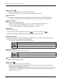
1.5.1
R/K measurement screen
1
The screen for the AR (Refractive error) and KM (Corneal curvature radius) measurements has Page
1 and Page 3.
The difference between Page 1 and Page 2 lies only in button icons displayed on the right of the
screen. Page 1 is provided with frequently-used button icons.
<When Page 1 is displayed>
Mode mark
Auto-tracking mark
Auto-shooting mark
Measured eye
RKT button
CYL mode
ᵏ
R/K button
Target
Auto button
Focusing indicator
Min. pupil mark
Manual mode button
Measured values
ᴥᴶᴦ
ᵏᴷᴰǽǽ
ǽǽǽᵈᴷᴰǽ
ᵐᴪǽᴮ ᴫᴯᴲǽᵏᴮǽǽᴴᴫᴶᴵǽᴮᴴᴰ
ᵀᴪǽᴭ ᴫᴴᴲǽᵏᴯǽǽᴴᴫᴲᴶǽǽᴵᴰ
ᴾǽǽǽǽǽᴯ
Ring image enlargement button
Mire ring
Page button
Patient’s eye
Indicates the right or left eye of the patient.
RKT button (
)
Selects a measurement mode.
The measurement mode switches in the following order: NT measurement mode→ RKT measurement mode (R/K
and NT continuous measurements) → R/K measurement mode→ NT measurement mode......
Target
Used as a guide to locate the patient's eye in the center of the screen. Align the mire ring projected on the
patient's eye with the target.
: When the patient's eye is not recognized.
: When the patient's eye is recognized.
9
BEFORE USE: Measurement Screen Description
Auto button (
)
Selects the auto-tracking function and auto-shooting function.
Select auto-tracking from 3D, 2D or OFF. Select auto-shooting from ON or OFF.
Min. pupil mark
The concentric circle displayed by eight bright points indicates the minimum measurable pupil size.
If the pupil is smaller than this mark or eyelashes obscure this mark, measurement may not be possible.
Measured values
Displays the latest measured results.
Numeric values displayed to the right of “R: ” and “K: ” are the respective measurement count.
The numeric value in parentheses displayed to the right of “R: ” is a confidence index.
* “P: ” is not displayed when the 43. CONF. INDEX parameter is set to NO.
Mode mark
Indicates the set mode.
The set mode is indicated by the R/K mode mark (
) and the NT mode mark (
).
When the two marks are displayed at the same time, the set mode is RKT mode.
Auto-tracking mark
Indicates the setting of the auto-tracking function (alignment in the up, down, left, right, back and forth
directions and focusing in the back and forth direction).
The TONOREF II displays 3D, 2D or Manual (No indication).
Auto-tracking in the back-and-forth, side-to-side and up-and-down directions is turned on.
Auto-tracking in the side-to-side and up-and-down directions is turned on.
(No
Manually align the device and bring the eye into focus.
indication)
Auto-shooting mark
Indicates the setting of the auto-shooting function.
Measurement starts automatically when the eye is best aligned and focused.
(No
indication)
Press the start button to start measurement.
CYL mode
Indicates the selected cylinder mode.
R/K button (
)
Selects a measurement mode in R/K measurement.
Select from AR/KM measurement mode, AR measurement mode or KM measurement mode. The selected
measurement mode is displayed on the screen.
Pressing the button switches the mode in the following order: AR/KM measurement mode (AR and KM continuous
measurements) → AR measurement mode (AR measurement)→ KM measurement mode (KM measurement)→
AR/KM measurement mode......
10
BEFORE USE: Measurement Screen Description
Focusing indicator
Indicates the distance between the main body and the patient’s eye.
Operate the joystick until you can obtain the proper focus (
Manual mode button (
).
)
1
Turns off both the auto-tracking and auto-shooting functions (manual mode).
The auto-tracking mark and auto-shooting mark become blank (
), indicating that these functions are
turned off. Pressing the manual mode button returns to the state before the manual mode button was pressed.
See “2.4.1 Switching to manual mode” (page 37) for details on manual mode.
Ring image enlargement button (
)
ᵏ
Switches to the ring image full screen by pressing this button
when the thumbnail of the measurement ring is displayed after
AR measurement.
ǁᵃᵆᵋᵆᵐᵅǂ
See “{ Measurement ring image display” (page 48) for details.
ᴥᴶᴦ
ᵏᴷᴰǽǽ
ǽǽǽᵈᴷᴰ
ᵐᴪǽᴮ ᴫᴯᴲǽᵏᴮǽǽᴴᴫᴶᴵǽᴮᴴᴰ
ᵀᴪǽᴭ ᴫᴴᴲǽᵏᴯǽǽᴴᴫᴲᴶǽǽᴵᴰ
ᴾǽǽǽǽǽᴯ
Thumbnail
Mire ring
Used as an alignment reference ring.
When the auto-tracking function is on (3D or 2D), bring the mire ring close to the target so that the device
automatically starts alignment.
When the auto-tracking function is off, bring the patient’s eye into focus so that the mire ring is placed within the
target.
If the eyelid or eyelashes are on this mark, KM measurement may not be possible.
Page button (
,
,
)
Switches the measurement screen among Page 1, Page 2 and Page 3.
Pressing the button switches the page in the following order: Page 1→ Page 2→ Page 3→ Page 1→ ......
The displayed icons vary according to the selected page.
There is no Page 3 for NT mode.
11
BEFORE USE: Measurement Screen Description
<When Page 2 is displayed>
*
CS, PS, and PD data, and cataract measurement mode mark are displayed on each page.
CAT measurement mode
mark
ᵏ
CYL mode button
PS (Pupil Size) indication
CS (Corneal Size) indication
CS/PS/PD button
㧼㧿ޓ㧤㧚㧜
Eyeprint button
ᴥᴶᴦ
㧯㧿㧝㧞㧚㧜
ᵏᴷᴰǽǽ
ǽǽǽᵈᴷᴰǽ
ᵐᴪǽᴮ ᴫᴯᴲǽᵏᴮǽǽᴴᴫᴶᴵǽᴮᴴᴰ
ᵀᴪǽᴭ ᴫᴴᴲǽᵏᴯǽǽᴴᴫᴲᴶǽǽᴵᴰ
ᴾǽǽǽǽǽᴯǽǽǽǽǽǽǽǽǽᵍᵁᴳᴱ
PD (Pupillary Distance) indication
CAT measurement mode mark (
)
Indicates that the eye has been measured in cataract measurement mode.
If cataract or abnormal eyes cannot be measured, cataract measurement mode is automatically turned on.
See “{ CATARACT measurement mode” (page 47) for details on cataract measurement mode.
PS (Pupil Size) indication
Displayed when PS (Pupil Size) is measured. (increments: 0.1 mm)
CS (Corneal Size) indication
Displayed when CS (Corneal Size) is measured. (increments: 0.1 mm)
CYL mode button (
)
Switches cylinder mode, the reading direction of cylinder data in which CYL data is represented.
CYL-
Indicates the cylindrical power by - reading.
CYL+
Indicates the cylindrical power by + reading.
CYL±
Cylinder data is indicated by + reading when the refractive error is positive for any axis
angle.
Indicates the cylindrical power by - reading in other cases.
Cylinder mode can be switched even after measurement.
Data is printed out with the mode status at the time of printing.
CS/PS/PD button (
)
Switches from AR/KM measurement to CS/PS/PD measurement.
Pressing this button switches the measurement mode in the following order: CS measurement→ PS
measurement→ Manual PD measurement→ CS measurement......
To return to AR/KM measurement from CS/PS/PD measurement, press the exit button
12
.
BEFORE USE: Measurement Screen Description
Eyeprint button (
)
Prints the eyeprint view of measured data.
The eyeprint is printed out regardless of its parameter setting.
See “2.7.2 Eyeprint” (page 74) for details on the eyeprint.
1
PD (Pupillary Distance) indication
Displayed when PD (Pupillary Distance) is measured (increments: 1 mm).
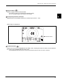
<When Page 3 is displayed>
ᵏ
Parameter button
ᴥᴶᴦ
ᵏᴷᴰǽǽ
ǽǽǽᵈᴷᴰǽ
ᵐᴪǽᴮ ᴫᴯᴲǽᵏᴮǽǽᴴᴫᴶᴵǽᴮᴴᴰ
ᵀᴪǽᴭ ᴫᴴᴲǽᵏᴯǽǽᴴᴫᴲᴶǽǽᴵᴰ
ᴾǽǽǽǽǽᴯǽǽǽǽǽǽǽǽǽᵍᵁᴳᴱ
Parameter button (
)
Switches the screen to the PARAMETER SETTING screen. Pressing the button for about a second switches
the screen to the PARAMETER SETTING screen.
The PARAMETER SETTING screen is used to set parameters, date and time, and enter comments.
13
BEFORE USE: Measurement Screen Description
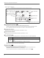
1.5.2
NT measurement screen
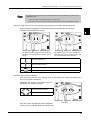
The following is the screen for NT (Tonometry) measurement.
<When Page 1 is displayed>
Mode mark
Auto-tracking ON mark
Applanation area
Auto-shooting ON mark
Patient’s eye
Charge indicator
RKT button
Measurement
button
ᵏ
Target
Focusing indicator
Auto button
Measured values
ǽ
ǽ ᴮᴲǽǽǽ ᴮᴱ
ǽ ᴮᴲǽǽǽ ᴮᴱ
ǽ ᴮᴰǽǽǽ ᴮᴱ
ÁÐÃᴱ°
ǽ ᴮᴱ®ᴭǽ ᴮᴱ®ᴭ
ÁÖ ¯ µ
ÁÖ ¯ µ
R: Right eye
Target (
range
L: Left eye
Eyelid detection mode
button
Page button
Measurement range
)
Used as a guide to position the patient’s eye in the center of the screen during the NT measurement.
Measured values
Three pieces of measured data are shown. The latest measured data is shown at the top and the older data
is shown under the latest data.
The data in the bottom line preceded by “AV” is the average data.
“/ number” appended to the average data represents the number of items of measured data used for averaging.
Applanation area (
)
Represents the range in which air is puffed to the cornea.
Charge indicator
Indicates that the device is in standby mode for puffing air. While it is indicated, air cannot be puffed.
Range button (
)
Used to select the measurement range.
Every time the button is pressed, the measurement range switches in the following order: “APC 40” → “APC 60” →
“40” → “60” → “APC 40” → ….
The selected measurement range is displayed in the lower right of the screen.
When the power button is turned ON, “APC 40” is displayed by default.
For the details of the measurement range, see “2.6 NT (Tonometry) Measurement: NT Mode” (page 61).
Focusing indicator
Shows the distance between the patient’s eye and the air nozzle.
Manipulate the joystick until optimal focus (
14
) is attained.
BEFORE USE: Measurement Screen Description
Eyelid detection mode button (
)
Used to activate the detection (eyelid detection) mode which detects whether the eyelid is over the
applanation area or not.
Every time the button is pressed, the eyelid detection mode is
turned on or off.
Whether the eyelid detection mode is turned on or off is checked by
the eyelid detection cancel marker in the lower right of the screen.
Indication
The eyelid detection mode is
cancelled.
No indication
The eyelid detection mode is
activated.
For the details of the eyelid detection mode, see “2.6.1 Eyelid
detection mode” (page 70).
Page button (
,
ᵏ
1
ÁÖ ÁÖ ÁÐÃᴱ°
Eyelid detection mode marker
)
Switches the measurement screen among Page 1 and Page 3.
Pressing the button switches the page in the following order: Page 1→ Page 2→ Page 1→ ......
The displayed icons vary according to the selected page.
Measurement range
The selected measurement range is displayed.
The measurement range selected from “ACP40”, “ACP60”, “40” or “60” is displayed.
<When Page 2 is displayed>
Parameter button (
)
ᵏ
Switches the screen to the PARAMETER SETTING screen.
Pressing the button for about a second switches the screen
to the PARAMETER SETTING screen.
ÁÖ ÁÖ ÁÐÃᴱ°
Parameter button
15
BEFORE USE: Labels and Indications on the Device
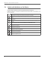
1.6
Labels and Indications on the Device
To call the operator’s attention, the device is provided with labels and indications.
If labels are curling up or characters are faded and become barely legible, contact NIDEK or your
authorized distributor.
Indicates that important descriptions are contained in the operator’s manual and that
the operator must refer to the operator's manual prior to operation.
Indicates that the degree of protection against electric shock is of a Type B Applied
Part.
Indicates that when the switch is pressed to this symbol side, power is not supplied to
the device.
Indicates that when the switch is pressed to this symbol side, power is supplied to the
device.
Indicates that the device must be supplied only with alternating current.
Indicates the input port.
Indicates the output port.
Indicates the date of manufacture.
Indicates the manufacturer.
Indicates that this product shall be disposed of in a separate collection of electrical and
electronic equipment in EU.
16
BEFORE USE: Labels and Indications on the Device
1
[Underside view]
17
BEFORE USE: Checking Contents
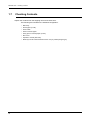
1.7
Checking Contents
Unpack the contents from the shipping carton and check them.
The following are included in the standard configuration.
• Main body
• Printer paper (3 rolls)
• Power cable
• Pack of chinrest paper
• Fixing pins for chinrest paper (2 units)
• Dust cover
• Operator’s manual (this book)
• Model eye for R/K measurement/Contact Lens (CL) holder (integral type)
18
BEFORE USE: Before First Use
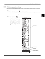
1.8
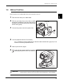
Before First Use
Place the device on a stable table and connect a power cord to it.
1
2
1
Place the main body on a stable table.
Pull the main body fully to the side on which
the device is laid down, lock the main body to
the base unit with the locking lever and lay the
device down gently.
3
Connect the power cord to the power inlet.
4
Connect peripheral devices if necessary.
Power inlet
See “3 OPERATION WHEN PERIPHERAL DEVICES ARE CONNECTED” (page 93) for the
method of connecting peripheral devices.
5
6
Stand up the device upright.
Make sure that the power switch is turned off
( ) and plug the power cord in the wall outlet.
Power switch
CAUTION • The electrical outlet must have a grounding terminal.
Electric shock or fire may occur in the event of device malfunction or power leakage.
19
BEFORE USE: Before First Use
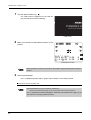
7
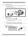
Turn the power switch on (
).
The initial screen is displayed on the LCD display and the device starts initializing.
Initial screen
8
Make sure that the measurement screen is displayed.
ᵏ
ᴥǽᴦ
ᵏᴷᴭǽǽ
ǽǽǽᵈᴷᴭ
ᵐᴨǽᴭᴫᴭᴭǽᵏᴮǽǽᴭᴫᴭᴭǽǽǽᴭ
ᵀ ᴪǽᴭ ᴫᴭᴭǽᵏᴯǽ ᴭᴫᴭᴭǽǽǽᴭ
ᴾǽǽǽǽǽᴭ
Measurement screen
• When the device is used for the first time, “NO PAPER” appears indicating that no paper is
loaded.
9
Set the printer paper.
See “4.3 Replacing Printer Paper” (page 106) for details on the setting method.
This is all you have to do before use.
• Set the parameters to suit your needs or preferences.
See “2.8 Parameter Settings” (page 76) for the parameters and their setting methods.
• See “3 OPERATION WHEN PERIPHERAL DEVICES ARE CONNECTED” (page 93) for
the method of connecting peripheral devices.
20
BEFORE USE: Before First Use
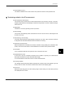
{ Please see here when you want to do like this.
When
Refer to the following.
You need to know the details of the “MEASURING
WINDOW CHECKING” message displayed at device
start-up.
“2.2.1 Measuring window check for soiling and puffed
air pressure check during startup” (page 29)
Auto-tracking or auto-shooting does not work depending
on eye to be measured.
NOTE of “2.5.1 AR (refractive error) and KM (corneal
curvature radius) measurements: AR/KM
measurement mode” (page 39)
Measured results are error indications.
NOTE of “2.5.1 AR (refractive error) and KM (corneal
curvature radius) measurements: AR/KM
measurement mode” (page 39)
Measuring monocular PD
“{ Manual PD Measurement” (page 57)
You need to know CAT mark displayed on screen during
measurement.
“{ CATARACT measurement mode” (page 47)
Changing contents to be printed
“2.7.1 Printing measured data” (page 71)
Setting date and time to be printed
“2.8.2 Setting the date and time” (page 89)
Printing shop name
“2.8.3 Entering comments” (page 91)
Printing eye print only
“2.7.2 Eyeprint” (page 74)
Transferring data by connecting AOS series or COS
series
“3.1 Connecting to the NIDEK Motorized Refractor
(RT) or Computer” (page 93)
Connecting lensmeter and print data with TONOREF II
“3.2 Connecting to the NIDEK Auto Lensmeter (LM)”
(page 95)
Resetting all parameters to their defaults
“{ Resetting the parameters” (page 78)
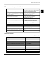
{ Setting by parameter
Setting parameters allows various functions of the device. See “2.8 Parameter Settings” (page 76) for
details.
Setting contents
Parameters
Display step of SPH CYL, and AXIS data
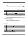
1. STEP, 3. AXIS STEP
Way of fogging for AR serial measurement
4. MEAS MODE
Presence of AI mode
5. AI MODE
Measurement count of AR continuous measurement
6. AR CONTINUE
Whether or not to display the measurement ring thumbnail
7. AR THUMBNAIL
Display unit of KM measurement (mm/D)
11. KM UNIT
Display format of KM measurement (R1,R2/ AVE,CYL)
12. KM DISPLAY
Corneal refractive index used for KM measurement
13. REF. INDEX
Measurement count of KM continuous measurement
14. KM CONTINUE
Handling method of low confidence data during NT
measurement
21. SET LOW CONF to 23. LOW CONF
ALARM
Whether or not the fixiation LED blinks during NT measurement
24. FIX LED BLINK
21
1
BEFORE USE: Before First Use
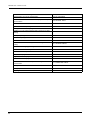
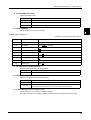
Setting contents
22
Parameters
Measurement count of NT measurement
25. NT CONTINUE
Whether NT measurement values are displayed in fixed-point
representation
26. DECIMAL DIGIT
Measurement interval of NT measurement
27. MEAS INTERVAL
Operation method of printing
31. PRINT
Printing with narrow line-spacing
32. ECONO. PRINT
Whether or not to erase measured data in memory just after
printing
33. PRINT&CLEAR
Density of printing text
34. PRINT DENCITY
Contents of printing
35.PATIENT NO. to 55. NEAR PD PRINT
Distance of PD for near vision
56. WORKING D.
Whether or not to automatically check measuring window for
soiling.
61. WINDOW CHECK
Contents that change by pressing auto button
62. TRACKING SW
Whether PD is automatically measured or not
63. AUTO PD
Time after which sleep mode is activated
64. SLEEP
Volume of beeping
65. BEEP
Brightness of LCD display
66. AR BRIGHTNESS, 67. NT BRIGHTNESS
Whether or not to display touch icons on measurement screen
68. ICON OFF
Whether or not to check the air pressure during NT
measurement
71. PRESSURE CHECK
Change mode of RKT mode
72. CHANGE MODE
Change speed of RKT mode
73. CHANGE SPEED
Target type of NT measurement
74. TARGET TYPE
2.
2.1
OPERATING PROCEDURES
Operation Flow
Turning ON the device
2
2.2 Preparation for Measurement (page 24)
Turn on the device and configure it us as necessary.
Set up the patient.
2.4 Selecting the Mode (page 35)
Measurement
2.5 AR (refractive error) and KM (corneal curvature radius) Measurements (page 39)
{ CATARACT measurement mode (page 47)
{ Measurement ring image display (page 48)
2.5.2 AR (refractive error) Measurement: AR Measurement Mode (page 49)
2.5.3 KM (corneal curvature radius) Measurement: KM Measurement Mode (page 51)
2.5.4 CS (Corneal Size) Measurement (page 53)
2.5.5 PS (Pupil Size) Measurement (page 55)
2.5.6 PD (Pupillary Distance) Measurement (page 57)
2.6 NT (Tonometry) Measurement: NT Mode (page 61)
Printout
2.7 Printing (page 71)
* For transferring data to connected devices:
3 OPERATION WHEN PERIPHERAL DEVICES ARE CONNECTED (page 93)
Turning OFF the device
2.3 Finishing the Measurements (page 33)
* For lens prescription for the correction of visual acuity using spectacle etc., subjectively test the
patient’s visual acuity with reference to AR-measured data.
23
OPERATING PROCEDURES: Preparation for Measurement
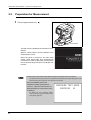
2.2
Preparation for Measurement
1
Turn the power switch on (
).
Power switch
The title screen is displayed and the device is initialized.
Wait for a while until the screen switches to the
measurement screen.
When the power is turned on, the main body
makes small side-to-side and back-and-forth
movements in order to determine the initial position for auto-tracking; this does not indicate malfunction.
Initial screen
• Avoid turning on the power switch while the patient is seated in front of the device.
The chinrest is not moved up or down to the origin because the patient sensor detects the presence of the
patient and judges that the patient’s chin is placed over the chinrest.
• When the WINDOW CHECK and
PRESSURE CHECK parameters are
turned on, respective check screens are
displayed before the measurement screen
is displayed.
For details, see “2.2.1 Measuring window
check for soiling and puffed air pressure check
during startup” (page 29).
㧼㧾㧱㧿㧿㨁㧾㧱ޓ㨀㧱㧿㨀ޓ㧹㧻㧰㧱
ޓޓޓ
㧯㧴㧱㧯㧷㧵㧺㧳ޓޓ㧠㧜
ޓ
ޓޓ
ޓ
ޓ
ޓ
ޓ
ޓ
ޓ
ޓ
Pressure test mode screen
24
OPERATING PROCEDURES: Preparation for Measurement
2
The measurement screen is displayed.
The measurement screen with the measurement mode (R/K or NT measurement) selected
just before the last shutdown is displayed.
ᵏ
ᴥǽᴦ
ᵏᴷᴭǽǽ
ǽǽǽᵈᴷᴭ
ᵐᴨǽᴭᴫᴭᴭǽᵏᴮǽǽᴭᴫᴭᴭǽǽǽᴭ
ᵀ ᴪǽᴭ ᴫᴭᴭǽᵏᴯǽ ᴭᴫᴭᴭǽǽǽᴭ
ᴾǽǽǽǽǽᴭ
2
R/K measurement screen
ᵏ
ÁÖ ÁÖ ÁÐÃᴱ°
NT measurement screen
• “NO PAPER” is displayed on the screen if the power switch is turned on with no printer
paper loaded.
Load the printer paper.
3
Perform checks before use.
Perform the following checks before use.
No error message appears.
The main body moves smoothly using the joystick.
The chinrest moves up and down by pressing the chinrest up/down button.
Printer supply is adequate.
Follow “4.1 Troubleshooting” (page 101) if abnormal conditions are encountered.
4
Establish the measurement conditions.
The following conditions should be specified:
1: Measurement contents, R/K measurement mode, auto-tracking mode, and auto-shooting mode
See “2.4 Selecting the Mode” (page 35) for details.
2: Parameter-set measurement conditions:
The device is provided with functions to be changed by various parameters related to measurements according to the operators’ needs.
See “2.8 Parameter Settings” (page 76) for details.
25
OPERATING PROCEDURES: Preparation for Measurement
3: CYL mode
Cylinder mode, the reading direction of cylinder data in which CYL data (cylindrical power) is represented during the measurement is selected by pressing the CYL mode button
.
Screen
display
CYL mode
CYL-
- reading
Indicates the cylindrical power by + reading.
CYL+
+ reading
Indicates the cylindrical power by - reading.
CYL±
Mix reading
Description
Indicates the cylindrical power by + reading when the refractive
error is positive for any axis angle.
Indicates the cylindrical power by - reading in other cases.
• Cylinder mode is changeable even after measurement.
• All items of the saved data are printed out with the mode selected at the time of printout.
• These settings are retained even after shutdown of the device; Change these
measurement conditions only if necessary.
5
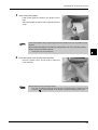
Prepare the patient.
1) Wipe the forehead rest and chinrest that contact the patient with clean absorbent cotton or
gauze dampened with rubbing alcohol.
Forehead rest
If chinrest paper is used, remove one piece for
each patient.
Chinrest
2) Instruct the patient to take off spectacles or
contact lenses and sit on a chair.
3) Have the patient place his/her chin on the chinrest as deeply as possible, and his/her
forehead on the forehead rest lightly.
26
OPERATING PROCEDURES: Preparation for Measurement
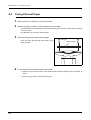
4) Adjust the height of the chinrest by the chinrest up/down button (
,
) until the center level of the patient's eye aligns with the
eye level marker.
Eye level marker
Before adjusting the height of the chinrest, inform
the patient that the chinrest moves up and down.
2
If the chinrest is at the upper (or lower) mechanical
limit, the upper limit mark
(or lower limit mark
ᵏ
) is displayed on the screen.
ᴥǽᴦ
ᵏᴷᴭǽǽ
ǽǽǽᵈᴷᴭ
ᵐᴨǽᴭᴫᴭᴭǽᵏᴮǽǽᴭᴫᴭᴭǽǽǽᴭ
ᵀᴪǽᴭ ᴫᴭᴭǽᵏᴯǽǽᴭᴫᴭᴭǽǽǽᴭ
ᴾǽǽǽǽǽᴭ
Limit mark
• When the TONOREF II displays a thumbnail in the R/K measurement, the limit mark (
) is covered and cannot be seen.
6
,
Perform the selected measurement.
For the contents of each measurement, see:
“2.5 AR (refractive error) and KM (corneal curvature radius) Measurements” (page 39)
“2.5.1 AR (refractive error) and KM (corneal curvature radius) measurements: AR/KM measurement mode” (page 39)
“2.5.2 AR (refractive error) Measurement: AR Measurement Mode” (page 49)
“2.5.3 KM (corneal curvature radius) Measurement: KM Measurement Mode” (page 51)
“2.6 NT (Tonometry) Measurement: NT Mode” (page 61)
In RKT mode, the measuring unit switches during the transition from the R/K to NT measurement.
For details, see “2.2.2 Switching between R/K measurement and NT measurement” (page 31).
• Instruct the patient not to blink during measurement. Additionally, instruct the patient not to
blink and open his/her eyes immediately before measurement to avoid measurement
failure.
• Instruct the patient to open both eyes wide during measurement.
Closing one eye may cause an unstable fixation and the other eye will not open wide.
27
OPERATING PROCEDURES: Preparation for Measurement
7
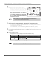
Print the measured results.
Printing operation varies according to the 31. PRINT parameter setting.
31. PRINT parameter
AUTO
MANUAL
NO
Printing method
Printing starts automatically at the completion of measurement.
Press the print button
to print the measured data out.
Printing does not occur.
See “2.7 Printing” (page 71) for the details on printing.
• Even when the 31. PRINT parameter is set to NO, data is exported to external connected
devices.
8
To measure the next patient, repeat from Step 5.
See “2.3 Finishing the Measurements” (page 33) for details on finishing measurements.
28
OPERATING PROCEDURES: Preparation for Measurement
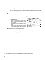
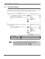
2.2.1
Measuring window check for soiling and puffed air pressure
check during startup
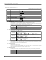
It is possible to parameter-set whether or not to check the measuring window for soiling and
the pressure of puffed air before measurements.
No.
Parameter name
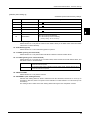
Description
61
WINDOW CHECK
Selection of whether or not to automatically check the measuring
window for soiling from YES, NO, and DAY.
71
PRESSURE CHECK
Selection of whether or not to automatically check the air pressure
from YES, NO, and DAY.
For the details of the parameter setting method, see “2.8 Parameter Settings” (page 76).
The soiled measuring window will adversely affect the reliability of measured results. It is
recommended to keep the measuring window clean with this window check function as well
as by visually checking the measuring window for soiling.
It is essential to maintain the accurate pressure of puffed air for the accurate tonometry. It is
recommended to check the pressure of puffed air before NT measurement.
Checks are performed in the following order: “Check of the pressure of puffed air (40 mmHg
and 60 mmHg)” → “Window check for soiling”
The checks disabled by the corresponding parameters are skipped.
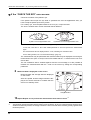
• For checking the measuring window, be sure that the front is not blocked by objects or
exposed to interference light.
Even if the window is not smudged, it may be determined that it is smudged due to objects or interference
light.
• At device start-up, do not stand or put objects in front of the measuring window.
If something is present in front of the measuring window within 1 m, the measuring window may not be
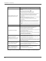
properly checked for soiling.
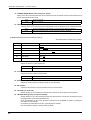
• All the checks are performed automatically.
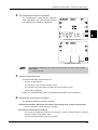
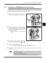
1) After the title screen is displayed, “PRESSURE TEST MODE / CHECKING 40” is displayed and the test of the puffed air of 40
mmHg is performed.
Wait until the check result is displayed.
㧼㧾㧱㧿㧿㨁㧾㧱ޓ㨀㧱㧿㨀ޓ㧹㧻㧰㧱
ޓޓޓ
㧯㧴㧱㧯㧷㧵㧺㧳ޓޓ㧠㧜
ޓ
ޓޓ
ޓ
ޓ
ޓ
ޓ
ޓ
ޓ
ޓ
29
2
OPERATING PROCEDURES: Preparation for Measurement
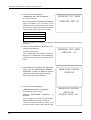
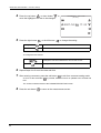
2) The check result is displayed.
• “PRESSURE TEST OK” is displayed:
The air nozzle is clean.
• If one of the following messages is displayed:
After the completion of all the checks, put the
TONOREF II into NT measurement mode, turn the
device off once and check the air nozzle for soiling.
If the air nozzle is soiled, wipe it clean of soling.
㧼㧾㧱㧿㧿㨁㧾㧱ޓ㨀㧱㧿㨀ޓ㧹㧻㧰㧱
ޓ
ޓ
ޓ
㧼㧾㧱㧿㧿㨁㧾㧱ޓ㨀㧱㧿㨀ޓ㧻㧷ޓ
ޓ
ޓ
ޓ
ޓ
ޓ
ޓ
ޓ
Error message
PRESSURE PEAK ERROR
PRESSURE SLOPE ERROR
NO PRESSURE UP
After the completion of the checks, the displayed “PRESSURE PEAK ERROR (40)” message is
printed out.
3) The test of the puffed air of 60 mmHg is performed in the same way.
Confirm the check result.
If the “PRESSURE PEAK ERROR” message is
displayed, the “PRESSURE PEAK ERROR (60)”
message is printed out after the completion of the
check.
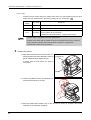
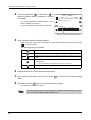
4) The measuring unit switches to the R/K measuring unit, the “MEASURING WINDOW /
CHECKING” message is displayed and the
measuring window is checked for soiling.
㧼㧾㧱㧿㧿㨁㧾㧱ޓ㨀㧱㧿㨀ޓ㧹㧻㧰㧱
ޓޓޓ
㧯㧴㧱㧯㧷㧵㧺㧳ޓޓ㧢㧜
ޓ
ޓޓޓ
ޓ
ޓ
ޓ
ޓ
ޓ
ޓ
ޓ
㧹㧱㧭㧿㨁㧾㧵㧺㧳ޓ㨃㧵㧺㧰㧻㨃
ޓޓޓޓ㧯㧴㧱㧯㧷㧵㧺㧳
Wait until the check result is displayed.
5) The check result is displayed.
㧹㧱㧭㧿㨁㧾㧵㧺㧳ޓ㨃㧵㧺㧰㧻㨃
• “WINDOW CHECK OK!” is displayed:
The measuring window is clean.
• “CHECK
MEASURING
displayed:
WINDOW.”
is
At the completion of the check, the “CHECK MEASURING WINDOW” message is printed out.
Check the measuring window for soiling. If the
measuring window is soiled, wipe it clean of soling.
30
ޓޓޓޓ㧯㧴㧱㧯㧷㧵㧺㧳
㨃㧵㧺㧰㧻㨃ޓ㧯㧴㧱㧯㧷ޓ㧻㧷㧍
OPERATING PROCEDURES: Preparation for Measurement
6) At the completion of the checks, the screen returns to the measurement screen.
• For the method of cleaning the measuring window and the air nozzle, see “4.6 Cleaning”
(page 111).
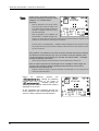
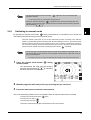
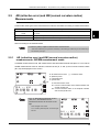
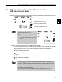
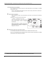
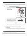
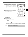
2.2.2
Switching between R/K measurement and NT measurement
When the measurement mode is switched from R/K measurement to NT measurement, the
measuring unit inside the main body is switched. To switch the measuring unit, pull the main
body fully toward the operator for safety.
<When the RKT mode is set to AUTO> (Refer to
for AUTO on the next page)
When the R/K measurement is completed in
RKT mode, the “PULL BACK” message is displayed, prompting the operator to pull the main
body toward the operator.
<When set to AUTO in the RKT mode>
ᵉ
ǁᵃᵆᵋᵆᵐᵅǂ
When the main body is pulled toward the operator, the measuring unit switches.
Ð Õ Ì Ì Â Á Ã Ë
ᵏᴷᴰǽǽᴥᴶᴦ
ǽǽǽᵈᴷᴰ
ᵐᴪǽᴮ ᴫ ° °ǽ ᵏᴮǽǽᴴᴫᴶᴵǽᴮᴴᴰ
ᵀᴪǽᴭ ᴫᴴᴲǽᵏᴯǽǽᴴᴫᴲᴶǽǽᴵᴰ
ᴾǽǽǽǽǽᴯ Ð Ä ¶ ²
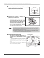
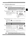
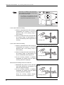
<When switching from R/K mode to NT mode>
When switching the measurement mode from R/
K mode to NT mode, the mode mark changes to
and the message, "PULL BACK" is displayed, prompting the operator to pull the main
body toward the operator.
<When switching from R/K mode to NT
mode>
ᵏ
ǁᵃᵆᵋᵆᵐᵅǂ
The Anterior segment observation screen is displayed in the upper right corner of the LCD.
When the main body is pulled toward the operator, taking care not to misalign the anterior segment to the right or left or up or down, switches
the measurement part.
Ð Õ Ì Ì Â Á Ã Ë
ᵏᴷᴰǽǽᴥᴶᴦ
ǽǽǽᵈᴷᴰ
ᵐᴪǽᴮ ᴫᴯᴲǽᵏᴮǽǽᴴᴫᴶᴵǽᴮᴴᴰ
ᵀᴪǽᴭ ᴫᴴᴲǽᵏᴯǽǽᴴᴫᴲᴶǽǽᴵᴰ
ᴾǽǽǽǽǽᴯ
Anterior segment observation screen
After switching is completed, the Anterior segment observation screen in the upper right corner of the LCD disappears.
The Anterior segment screen is displayed in the same manner when switching from NT
mode to RKT mode.
When the main body is already pulled towards the operator, the measurement part is switched without
displaying "PULL BACK" message.
31
2
OPERATING PROCEDURES: Preparation for Measurement
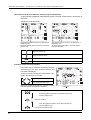
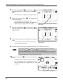
• In RKT mode, it is possible to select the
method of switching the measuring unit by
setting the “72. CHANGE MODE”
parameter.
ᵉ
ǁᵃᵆᵋᵆᵐᵅǂ
When the parameter is set to AUTO, pull the
main body toward operator according to the
“PULL BACK” screen indication after R/K measurement is completed to switch the mode to
NT mode automatically.
When the parameter is set to MANUAL, the
"PRESS START → CHANGE" message is dis-
Ð Ò Å Ó Ó Ó Ô Á Ò Ô ᴻ Ã È Á Î Ç Å
ᵏᴷᴰǽǽᴥᴶᴦ
ǽǽǽᵈᴷᴰ
ᵐᴪǽᴮ ᴫ ° °ǽ ᵏᴮǽǽᴴᴫᴶᴵǽᴮᴴᴰ
ᵀᴪǽᴭ ᴫᴴᴲǽᵏᴯǽǽᴴᴫᴲᴶǽǽᴵᴰ
ᴾǽǽǽǽǽᴯ Ð Ä ¶ ²
played on the screen when the main body is pulled toward the operator before the completion of R/K
measurement, which allows the measuring unit to be switched
Even with "AUTO", the "PRESS START → CHANGE" message is displayed on the screen when the main
body is pulled toward the operator before the completion of R/K measurement, which allows the measuring unit to be switched.
• If the presence of an obstacle in front of the air nozzle is detected while the R/K measuring
unit switches to the NT measuring unit, the “TOO CLOSE” message is displayed, which
cancels the switching of the measuring unit. After that, the “PRESS START → CHANGE”
message is displayed automatically.
After removing the obstacle, press the start button to resume switching the measuring unit.
• If the air nozzle is exposed to an intense light such as a spotlight or direct sunlight, the
“TOO CLOSE” message is displayed, disabling the R/K measuring unit from being
switched to the NT measuring unit.
Relocate or reorient the device or change the orientation of the illumination so as not to expose the air
nozzle to the intense illumination.
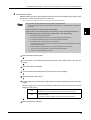
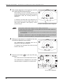
During
the
switching
process,
the
“
” (during the switching
process from R/K mode to NT mode) or
“
” message (during the
switching process from NT mode to R/K mode) is
displayed on the screen.
At the completion of the switching process, the
screen switches to the measurement mode; the
device is ready to perform the measurement.
32
ᵉ
ǁᵃᵆᵋᵆᵐᵅǂ
ᵏᴷᴰǽǽᴥᴶᴦ
ǽǽǽᵈᴷᴰ
ᵐᴪǽᴮ ᴫ ° °ǽ ᵏᴮǽǽᴴᴫᴶᴵǽᴮᴴᴰ
ᵀᴪǽᴭ ᴫᴴᴲǽᵏᴯǽǽᴴᴫᴲᴶǽǽᴵᴰ
ᴾǽǽǽǽǽᴯ Ð Ä ¶ ²
OPERATING PROCEDURES: Finishing the Measurements
2.3
Finishing the Measurements
2.3.1
Normal shutoff
1
Turn off (
) the power switch.
It is allowed to turn off the power with any screen displayed.
2
2
To exit measurements, inspect the measuring unit, air nozzle etc. for soiling and
clean them.
See “4.6 Cleaning” (page 111).
3
Put the dust cover over the device.
Always keep them clean for the next use.
• Be sure to put the dust cover on whenever the device is not in use.
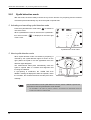
2.3.2
Shutoff before transporting the device
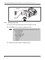
Before the device is transported, put the device in packing mode. In packing mode, the measuring unit
and chinrest are automatically set in preparation for transportation.
1
Inspect the measuring unit, air nozzle etc. for soiling and clean them.
See “4.6 Cleaning” (page 111).
2
Turn the power switch off (
) to shut off the device once.
3
Turn on the power switch (
) while pressing the chinrest down button
.
The device starts putting itself into packing mode. Wait for a while until a message is
displayed on the screen.
• If the Packing mode is performed with the air nozzle is exposed, the air nozzle recesses
and the shutter closes.
33
OPERATING PROCEDURES: Finishing the Measurements
4
When the “PACKING POSITION IS COMPLETED / SHUT DOWN PLEASE” message is
displayed, turn the power switch off ( ).
Ensure that the chinrest and measuring unit are
at their lower mechanical limits.
5
34
ǽ
ǽǽᵍᴾᵀᵈᵆᵋᵄǽᵊᵌᵁᵂ
ǽ
ǽᵍᴾᵀᵈᵆᵋᵄǽᵍᵌᵐᵆᵑᵆᵌᵋ
ǽǽǽᵆᵐǽᵀᵌᵊᵍᵉᵂᵑᵂᵁ
ᵐᵅᵒᵑǽᵁᵌᵔᵋǽᵍᵉᵂᴾᵐᵂǽ
ǽ
ǽ
Pull the main body fully to the side on which the main body is laid down, fix the
main body with the locking lever and gently lay down the device.
6
Disconnect the power cord, interface cables etc.
7
Raise the device and flip up the locking lever to unlock the main body.
8
Pack the device with the original packing material.
OPERATING PROCEDURES: Selecting the Mode
2.4
Selecting the Mode
Select the measurement mode from the following options:
Mode mark
Auto-tracking/auto-shooting ON mark
RKT button
R/K button
ᵏ
2
Auto button
ᴥǽᴦ
ᵏᴷᴭǽǽ
ǽǽǽᵈᴷᴭ
ᵐᴨǽᴭᴫᴭᴭǽᵏᴮǽǽᴭᴫᴭᴭǽǽǽᴭ
ᵀᴪǽᴭ ᴫᴭᴭǽᵏᴯǽǽᴭᴫᴭᴭǽǽǽᴭ
ᴾǽǽǽǽǽᴭ
R/K measured data
{ Measurement items
Select the measurements from R/K (Refractive error/corneal curvature radius) measurement and NT
(tonometry) measurement.
Press the RKT button
to select the mode.
On-screen
mode mark
Mode
Description
RKT mode
R/K measurement and NT measurement take place in a row: Both
eyes are R/K-measured first and then NT-measured.
R/K mode
R/K measurement only takes place.
NT mode
NT measurement only takes place.
{ Measurement modes in R/K mode
• In RKT mode, measurements normally take place in the order of: R/K measurement → NT
measurement
Select the measurements performed in R/K mode from AR (Refractive error) and KM (Corneal curvature radius) measurements.
Press the R/K button
Measurement item
AR/KM measurement
mode
on the R/K measurement screen.
Description
AR (refractive error) and KM (corneal curvature radius) measurements take
place in a row.
AR measurement mode
Only the AR (refractive error) measurement takes place.
KM measurement mode
Only the KM (corneal curvature radius) measurement takes place.
35
OPERATING PROCEDURES: Selecting the Mode
AR/KM measurement mode is selected by default; there is no need to select when proceeding to measurements in AR/KM measurement mode.
The items corresponding to the selected measurement mode are displayed on the screen.
ᵏ
ᵏ
ᴥǽᴦ
ᵏᴷᴭǽǽ
ǽǽǽᵈᴷᴭ
ᵐᴨǽᴭᴫᴭᴭǽᵏᴮǽǽᴭᴫᴭᴭǽǽǽᴭ
ᵀᴪǽᴭ ᴫᴭᴭǽᵏᴯǽǽᴭᴫᴭᴭǽǽǽᴭ
ᴾǽǽǽǽǽᴭ
AR/KM measurement mode
ᴥǽᴦ
ᵏᴷᴭǽǽ
ǽǽǽᵈᴷᴭ
ᵐᴨǽᴭᴫᴭᴭǽᵏᴮǽǽᴭᴫᴭᴭǽǽǽᴭ
ᵀᴪǽᴭ ᴫᴭᴭǽᵏᴯǽǽᴭᴫᴭᴭǽǽǽᴭ
ᴾǽǽǽǽǽᴭ
AR measurement mode
ᵏ
ᴥǽᴦ
ᵏᴷᴭǽǽ
ǽǽǽᵈᴷᴭ
ᵐᴨǽᴭᴫᴭᴭǽᵏᴮǽǽᴭᴫᴭᴭǽǽǽᴭ
ᵀᴨǽᴭ ᴫᴭᴭǽᵏᴯǽǽᴭᴫᴭᴭǽǽǽᴭ
ᴾǽǽǽǽǽᴭ
KM measurement mode
Every time the R/K button is pressed, the measurement mode switches in the following
order: AR/KM → AR → KM → AR/KM →….
{ Auto-tracking mode and auto-shooting mode
Specify the alignment (up-and-down and side-to-side directions) and focusing (back-and-forth direction) methods and the method of triggering measurements.
Specify the methods while holding down the auto button
Auto-tracking
36
autoshooting
On-screen
mark
.
Description
3D
ON
The auto-tracking in the back-and-forth, side-to-side and upand-down directions is turned on.
The measurements take place automatically when the device
is best aligned and focused on the eye.
3D
OFF
The auto-tracking in the back-and-forth, side-to-side and upand-down directions is turned on.
Press the start button to start measurements.
2D
ON
The auto-tracking in the side-to-side and up-and-down
directions is turned on.
The measurements take place automatically when the device
focused on the eye.
2D
OFF
The auto-tracking in the side-to-side and up-and-down
directions is turned on. Bring the eye into focus and press the
start button to start measurements.
OFF
ON
Manually align the device and bring the eye into focus.
The measurements take place automatically when the device
is best aligned and focused on the eye.
OFF
OFF
(No mark)
Manually align the device and bring the eye into focus.
Press the start button to start measurements.
OPERATING PROCEDURES: Selecting the Mode
• The functions assigned to the Auto button
parameter settings.
depend on the 28. TRACKING SW
For the setting method, see “2.8 Parameter Settings” (page 76).
• When the manual mode button
is pressed to turn off the auto-tracking and autoshooting modes (manual mode), the auto-tracking ON mark and auto-shooting ON mark
will be blanked (
).
2.4.1
Switching to manual mode
By pressing the manual mode button
2
during measurements, it is possible to turn off both the
auto-tracking and auto-shooting functions (manual mode).
Press the manual mode button to turn off the auto-tracking function according to the state the
patient’s eye after starting the measurement with the auto-tracking function on. (The manual mode
button functions even when the auto-shooting function only is turned on.) Allowing the operator to
turn off the auto-tracking and auto-shooting functions with a touch of the button, the manual mode
button saves the operator the trouble of pressing the auto button
repeatedly.
• For the eyes with a small pupil and with the corneal vertex shifted from the pupil center, if
the auto-tracking function is turned on and the pupil overlaps the min. pupil mark, the eye
may not be measured.
To measure such eyes, turn off the auto-tracking function and align the min. pupil mark with the pupil.
1
Press the manual mode button
measurements.
during
ᵏ
The auto-tracking ON mark and auto-shooting
ON mark will be blanked (
), indicating
that these functions are turned off.
ᴥᴶᴦ
ᵏᴷᴰǽǽ
ǽǽǽᵈᴷᴰǽ
ᵐᴪǽᴮ ᴫᴯᴲǽᵏᴮǽǽᴴᴫᴶᴵǽᴮᴴᴰ
ᵀᴪǽᴭ ᴫᴴᴲǽᵏᴯǽǽᴴᴫᴲᴶǽǽᴵᴰ
ᴾǽǽǽǽǽᴯ
2
Manually align the main body to the eye and bring the eye into focus.
3
Press the start button to start the measurement.
One of the following operations returns to the state before the manual mode button is pressed.
• Pressing the manual mode button
again
• Pressing the CLR button
• Pressing the print button
• Switch the measurement part (RK measurement and NT measurement).
37
OPERATING PROCEDURES: Selecting the Mode
2.4.2
Sleep mode
The device goes into sleep mode automatically to save power if no button have been pressed for a
certain period of time.
The time that the device goes into sleep mode can be selected from 5 minutes, 10 minutes,
15 minutes, or NO (no sleep mode) with the 64. SLEEP parameter (factory setting: 5 minutes).
Sleep mode places the device into the following conditions:
• The LCD display goes off.
• The memory indicator blinks.
The device recovers to normal mode from sleep mode by
the following methods:
• Press any button.
• Manipulate the joystick to move the base R or L.
Memory indicator
• Depending on the status of the LCD display, the device may not go into sleep mode.
When the PARAMETER SETTING screen is displayed, the device does not go into sleep mode.
38
OPERATING PROCEDURES: AR (refractive error) and KM (corneal curvature radius) Measurements
2.5
AR (refractive error) and KM (corneal curvature radius)
Measurements
In R/K mode, three types of the measurement modes are selectable according to measurement items.
Measurement item
Description
AR/KM measurement
mode
AR (refractive error) and KM (corneal curvature radius) measurements take place
in a row.
AR measurement mode
Only the AR (refractive error) measurements takes place.
KM measurement mode
Only the KM (corneal curvature radius) measurement takes place.
2
The same measurement procedure is followed in the above three modes; the displayed results are different according to the selected mode.
• To relax the patient, explain as follows before measurements.
“This device measures your eye with an infrared ray to find which type of lens fits you. The infrared ray is
not harmful to your eyes.”
2.5.1
AR (refractive error) and KM (corneal curvature radius)
measurements: AR/KM measurement mode
In AR/KM measurement mode, AR measurement and KM measurements take place in a row. When
AR/KM measurement mode is selected, refractive errors (S, C and A) and corneal curvature radius
(R1, R2) are displayed on the screen.
ᵏ
ᴥǽᴦ
ᵏᴷᴭǽǽ
ǽǽǽᵈᴷᴭ
ᵐᴨǽᴭᴫᴭᴭǽ ᵏᴮ ǽᴭᴫᴭᴭǽǽǽᴭ
ᵀᴪǽᴭ ᴫᴭᴭǽᵏᴯǽ ᴭᴫᴭᴭǽǽǽ ᴭ
ᴾǽǽǽǽǽᴭ
R: AR measurement count ( ): Confidence index
S: Spherical power
C: Cylindrical power
A: Cylinder axis
K: KM measurement count
R1: Corneal curvature radius of the flattest meridian and
corneal cylinder axis
R2: Corneal curvature radius of the steepest meridian
and corneal cylinder axis
• If the 12. KM DISPLAY parameter is set to
“AVE, CYL”, the indications on the
measurement screen are as shown on the
right
ᵏ
AVE: Averages of R1 and R2
CYL: Corneal cylindrical power and corneal cylinder axis
ᴥǽᴦ
ᵏᴷᴭǽǽ
ǽǽǽᵈᴷᴭ
ᵐᴨǽᴭᴫᴭᴭǽ Á Ö Å ǽ ᴭᴫᴭᴭǽǽǽᴭ
ᵀᴪǽᴭ ᴫᴭᴭǽ Ã Ù Ì ᴪǽ ᴭᴫᴭᴭǽǽǽᴭ
ᴾǽǽǽǽǽᴭ
39
OPERATING PROCEDURES: AR (refractive error) and KM (corneal curvature radius) Measurements
1
Instruct the patient to look through the measuring
window and watch the center of a picture of a balloon
without straining as he or she sees it.
Scenery picture with a balloon
2
Manipulate the joystick to display the
patient’s eye on the screen.
By pulling the joystick backward, pushing it
forward, tilting it to the left and right, the main
body moves back, forth, to the right, and to
the left. By turning the upper part of the joystick, the main body moves up and down.
Align the device to the patient’s eye with right,
left, up and down movements, and adjust the
focus with back and forth movements.
• If the mire ring is not in the center of the pupil and the min. pupil mark is on the iris, turn off
the auto-tracking function and bring the min. pupil mark into the center of the pupil to
perform measurement, ignoring the mire ring.
• Auto-tracking or auto-shooting may not work on keratoconus or postoperative cornea.
In such a case, turn off the auto-tracking and auto-shooting functions.
3
Perform alignment and focusing.
The methods of alignment and focusing vary
according to the 26. TRACKING SW parameter
setting.
*
Focusing indicator
KM measuring light
ᵏ
See “{ Auto-tracking mode and auto-shooting mode (
page 36) for details.
Perform alignment by placing the mire ring
reflected by the patient’s eye in the center of the
target.
ᴥᴶᴦ
Perform focusing according to the indication of ᵏᴷᴰǽǽ
ǽǽǽᵈᴷᴰǽ
ᵐᴪǽᴮ ᴫᴯᴲǽᵏᴮǽǽᴴᴫᴶᴵǽᴮᴴᴰ
the on-screen focusing indicator.
ᵀᴪǽᴭ ᴫᴴᴲǽᵏᴯǽǽᴴᴫᴲᴶǽǽᴵᴰ
ᴾǽǽǽǽǽᴯ
Mire ring
40
Target
OPERATING PROCEDURES: AR (refractive error) and KM (corneal curvature radius) Measurements
3D auto-tracking
1) Perform rough alignment and focusing by
manipulating the joystick to place in the
working range of auto-tracking.
Up-and-down and side-to-side alignment: Auto
2) When the device is placed within the
working range of auto-tracking, it automatically starts alignment and focusing.
2
Focusing: Auto
Up-and-down auto-tracking
1) Perform rough alignment and focusing by
manipulating the joystick to place in the
working range of auto-tracking.
Up-and-down alignment: Auto
Side-to-side alignment: Manual
2) When the device is placed within the
working range of auto-tracking, it automatically starts alignment in the up-and-down
direction.
3) Manipulate the joystick to move the mire
ring reflected on the patient’s eye within
the target.
Focusing: Manual
4) As the focusing indicator is displayed,
manipulate the joystick until the optimum focusing indicator is displayed.
Auto-tracking OFF
1) Manipulate the joystick to perform rough
Up-and-down and side-to-side alignment: Manual
alignment and focusing.
2) Manipulate the joystick to move the mire
ring reflected on the patient’s eye within
the target.
3) As the focusing indicator is displayed,
manipulate the joystick until the optimum
focusing indicator is displayed.
Focusing: Manual
During the focusing, maintain alignment
between the device and the patient’s eye.
• If eyelashes are on the min. pupil mark, correct AR measurement may not be possible. If
the eyelid or eyelashes are on the mire ring, KM measurement may not be possible.
In such cases, instruct the patient to open his/her eye wider.
If the patient cannot open wider, lift the patient’s lid, paying attention not to press against the eyeball.
41
OPERATING PROCEDURES: AR (refractive error) and KM (corneal curvature radius) Measurements
When the main body is not within the working range of auto-tracking:
As the limit mark is displayed, manipulate the joystick or chinrest up/down button in the direction of
the arrows.
<Examples of the limit mark>
ᵏ
ᵏ
ᵏᴷᴭǽᴥǽᴦ
ǽǽǽǽᵈᴷᴭ
ᵐᴨǽᴭᴫᴭᴭǽ ᵏᴮǽǽ ᴭᴫᴭᴭǽǽǽᴭ
ᵀᴪǽᴭ ᴫᴭᴭǽᵏᴯǽǽᴭᴫᴭᴭǽǽǽᴭ
ᴾǽǽǽǽǽᴭ
The level of the patient’s eye is too high from the
measuring unit.
Move the chinrest down to lower the level of the
patient’s eye.
ᴥǽᴦ
ᵏᴷᴭǽǽ
ǽǽǽ ᵈᴷᴭ
ᵐᴨǽᴭᴫᴭᴭǽ ᵏᴮǽ ᴭᴫᴭᴭǽǽǽᴭ
ᵀᴪǽᴭ ᴫᴭᴭǽᵏᴯǽǽᴭᴫᴭᴭǽǽǽᴭ
ᴾǽǽǽǽǽᴭ
The patient’s eye is too far to the left from the
measuring unit.
Tilt the joystick to the right to move the measuring unit to the right.
Move the chinrest up.
Move the chinrest down.
Tilt the joystick slightly to the right.
Tilt the joystick slightly to the left.
Indication of the focusing indicator:
If the main body is not within the working range of
auto-tracking in the back-and-forth direction, the
limit mark is displayed
ᵏ
As the limit mark is displayed, manipulate the joystick in the direction of the mark.
Push the joystick forward.
Pull the joystick backward.
Move the joystick back and forth until the focusing
indicator shows the optimum condition.
ᵏᴷᴭǽᴥǽᴦ
ǽǽǽǽ ᵈᴷᴭ
ᵐᴨǽᴭᴫᴭᴭǽ ᵏᴮǽǽᴭᴫᴭᴭǽǽǽᴭ
ᵀᴪǽᴭ ᴫᴭᴭǽᵏᴯǽǽᴭᴫᴭᴭǽǽǽᴭ
ᴾǽǽǽǽǽᴭ
Limit mark
Too close to the patient’s eye
Pull the joystick backward to move the main body away
from the patient’s eye.
Optimum condition
Push the joystick forward to move the main body toward the patient’s eye.
Too far from the patient’s eye
42
OPERATING PROCEDURES: AR (refractive error) and KM (corneal curvature radius) Measurements
4
Measurement starts.
Measurements take place automatically when the device is best aligned and focused on the
eye (when the auto-shooting function is turned on).
*
When the auto-shooting function is turned off, press the start button to start measurement.
• The operator can start measurement by pressing the start button.
Press the start button to start measurement when measurement has difficulty starting for patient’s who
blink often.
• Instruct the patient not to blink during measurement.
• When an error or error data appears, the cause may be one of those described below. If
those signs appear again after repeating measurement, check the following:
2
a. Patient blinked during measurement.
b. The eyelid or eyelashes are on the min. pupil mark during AR measurement.
c. The eyelid or eyelashes are on the mire ring during KM measurement.
d. The patient’s pupil is smaller than the min. pupil mark.
Have the patient sit in a dark room for a while and wait until the pupil diameter becomes large
enough for measurement.
e. Retinal reflection is extremely low due to an optical disease such as a cataract.
f. There is some unusual reflection on the cornea during measurement.
g. There is an extreme distortion on cornea.
KM measurement takes place.
A short beep is produced and KM-measured data and measurement count are displayed.
KM measurement completes.
Pre-AR measurement takes place and the scenery chart is fogged.
AR measurement takes place.
A short beep is produced and the AR measured data and measurement count are displayed.
The way of fogging in the second and subsequent measurements varies according to the 4. MEAS
MODE parameter setting.
CON.
Fogging is maintained on throughout the serial measurement.
This mode is useful for children who do not fixate their eyes very long.
NOR.
The patient’s view is fogged for each measurement even though the start
button is held down.
This mode is useful for patients who accommodate their eyes easily.
AR measurement completes.
43
OPERATING PROCEDURES: AR (refractive error) and KM (corneal curvature radius) Measurements
• If the device gets out of alignment and focus during measurement, the measurement is
interrupted. If the measurement is retried, the measured results are added to the former
results and stored.
• To continue the measurement, press the start button again. “<<FINISH>>” disappears and
auto-tracking starts for measurement. (except when the 31. PRINT parameter is set to
AUTO).
• The device can store up to 10 measurements each for the right eye and left eye. If
measurements exceed 10, the data is cleared in order from the oldest.
<AR measurement error messages>
Error message
Details
Measurement is impossible due to blinking and slight
movement of the eye.
Instruct the patient not to blink or not to move the eye until
BLK
(Blinking of the eye)
measurement is completed.
After
the
eye
stopped
blinking
and
moving,
perform
measurement again.
This error also may occur when reflected light from fundus is
low.
ALM
(Alignment error)
+OVR
(Positive SPH range over error)
-OVR
(Negative SPH range over error)
COVR
(CYL range over error)
CONF
(Measured data reliability error)
S, C, A data displayed in yellow
(Measured data reliability error)
Focusing is not proper.
Perform focusing and measurement again.
Spherical power is over the measurable limit of the + side.
Spherical power is over the measurable limit of the - side.
Cylindrical power is over the measurable limit.
Low-reliability data is obtained.
Measure the subject again.
* When the 44. ERROR DATA parameter is set to NO
Low-reliability data is obtained.
Measure the subject again.
* When the 44. ERROR DATA parameter is set to YES
<KM measurement error messages>
Error message
BLK
(Blinking of the eye)
Details
Measurement is impossible because of blinking and slight
movement of the eye.
Instruct the patient not to blink or not to move the eye until
measurement is completed.
After the eye stopped blinking and moving, perform measurement
again.
ALM
(Alignment error)
FAR
(Focus error: Too far from the patient’s eye)
NEAR
(Focus error: Too close to the patient’s eye)
44
Focusing is not proper.
Perform focusing and measurement again.
Focusing is not proper.
Perform focusing and measurement again.
Focusing is not proper.
Perform focusing and measurement again.
OPERATING PROCEDURES: AR (refractive error) and KM (corneal curvature radius) Measurements
+OVR
Positive corneal curvature radius range over
error)
-OVR
(Negative corneal curvature range over error)
COVR
(CYL range over error)
5
The corneal curvature radius is too large and over the
measurable limit.
The corneal curvature radius is too small and beyond the
measurable limit.
The cylindrical power is over the measurable limit.
Measurement completes.
• When AI mode is YES:*1
When the specified number of KM measurements is performed, the measurement automatically
completes.*2
When the specified number of AR measurements is performed and the data is stable (no variations), the measurement automatically completes.*3
Indications on the screen after the measurement:
“<<FINISH>>” is displayed on the screen.
When the specified number of KM measurements
have not been obtained, “<<KM?>>” is displayed
on the screen.
When the start button is pressed, KM measurement stars again. As soon as the specified number
of KM measurements is obtained, “<<FINISH>>” is
displayed on the screen.
• When AI mode is NO:
ᵏ
ǁᵃᵆᵋᵆᵐᵅǂ
ᴥᴶᴦ
ᵏᴷᴰǽǽ
ǽǽǽᵈᴷᴰ
ᵐᴪǽᴮ ᴫᴯᴲǽᵏᴮǽǽᴴᴫᴶᴵǽᴮᴴᴰ
ᵀᴪǽᴭ ᴫᴴᴲǽᵏᴯǽǽᴴᴫᴲᴶǽǽᴵᴰ
ᴾǽǽǽǽǽᴯ
When the specified number of KM measurements*2 is performed, the measurement automatically
completes.
When the specified number of AR measurements*3 is performed, the measurement automatically
completes.
Release the start button to finish AR measurement.
Indications on the screen after measurement:
When the specified number of KM measurements have not been obtained, “<<KM?>>” is displayed on the screen.
When the start button is pressed, the KM measurement stars again. As soon as the specified
number of KM measurements is obtained, “<<FINISH>>” is displayed on the screen.
*
If three or more measurements are obtained, the median values are printed at the time of printing.
A thumbnail of the measurement ring image is displayed when measurement is completed.
If necessary, check the full screen ring image.
See “{ Measurement ring image display” (page 48) for details on the ring image display.
*1.
*2.
*3.
In this mode, AR measurement automatically completes as soon as stable data is obtained by the specified number of measurements.
3 through 10 times can be set by the 14. KM CONTINUE parameter. (Factory setting is 3 times.)
3 through 10 times can be set by the 6. AR CONTINUE parameter. (Factory setting is 3 times.)
45
2
OPERATING PROCEDURES: AR (refractive error) and KM (corneal curvature radius) Measurements
6
Measure the other eye in the same manner.
ᵉ
When the other eye is set in front of the measuring unit, the measuring unit returns to the origin
in the back-and-forth and side-to-side directions.
ǁᵃᵆᵋᵆᵐᵅǂ
When measuring a single eye only, perform NT
measurement.
ᵏᴷᴰǽǽᴥᴶᴦ
ǽǽǽᵈᴷᴰ
For the method of switching to NT measurement, ᵐᴪǽᴮ ᴫ ° °ǽ ᵏᴮǽǽᴴᴫᴶᴵǽᴮᴴᴰ
see “2.2.2 Switching between R/K measurement and ᵀᴪǽᴭ ᴫᴴᴲǽᵏᴯǽǽᴴᴫᴲᴶǽǽᴵᴰ
ᴾǽǽǽǽǽᴯ Ð Ä ¶ ²
NT measurement” (page 31).
• Instruct the patient to close his/her eye before starting the next measurement.
Let the eye rest to avoid measurement failure by blinking.
7
In RKT mode, the measurement mode switches to NT measurement mode.
For the method of switching to NT measurement, see “2.2.2 Switching between R/K measurement and NT measurement” (page 31).
For NT measurement, see “2.6 NT (Tonometry) Measurement: NT Mode” (page 61).
8
9
Let the patient know that the measurement is completed and instruct him or her to rest
comfortably.
Print the measured results.
Printing operation varies according to the 31. PRINT parameter setting.
31. PRINT parameter
AUTO
MANUAL
NO
Printing method
Printing starts automatically at the completion of measurement.
Press the print button
to print the measured data out.
Printing does not occur.
See “2.7 Printing” (page 71) for details on printing.
• The printing contents can be changed by parameter settings.
See “2.8 Parameter Settings” (page 76) for details.
46
OPERATING PROCEDURES: AR (refractive error) and KM (corneal curvature radius) Measurements
{ CATARACT measurement mode
If cataract or abnormal eyes cannot be measured during AR (refractive error) measurement, cataract
measurement mode turns on automatically.
In cataract measurement mode, measurement conditions are changed so as to enhance ease of measurements of even cataract or abnormal eyes.
When the device is placed in cataract measurement mode,
“
ᵏ
” is displayed on the screen and then measurement
2
starts.
The auto-tracking and auto-shooting functions
work in the same manner as ordinary measurement mode.
ᴥᴶᴦ
ᵏᴷᴰǽǽ
ǽǽǽᵈᴷᴰǽ
ᵐᴪǽᴮ ᴫᴯᴲǽᵏᴮǽǽᴴᴫᴶᴵǽᴮᴴᴰ
ᵀᴪǽᴭ ᴫᴴᴲǽᵏᴯǽǽᴴᴫᴲᴶǽǽᴵᴰ
ᴾǽǽǽǽǽᴯ
One of the following operations cancels cataract measurement mode:
• Switching the eye to be measured between the right eye and left eye.
• Pressing the clear button
• Pressing the print button
.
.
• In cataract measurement mode, take note that measurement variations may occur more
commonly compared to normal measurement mode.
Printout sample in cataract measurement mode
According to the 45. CAT MARK parameter setting, “ ” indicating that measurement has been
taken in cataract measurement mode is printed
as shown on the right.
* Factory setting: NO
Symbols of cataract measurement mode
47
OPERATING PROCEDURES: AR (refractive error) and KM (corneal curvature radius) Measurements
{ Measurement ring image display
The TONOREF II projects measurement beams on the patient’s fundus and computation is performed
by capturing the reflected beams as a ring image to measure the refractive errors of the patient’s eye.
The TONOREF II displays this ring for the operator to observe the patient’s eye.
1
Perform normal measurement.
A thumbnail of the ring image is displayed along
with “<<FINISH>>” when measurement is complete.
ᵏ
ǁᵃᵆᵋᵆᵐᵅǂ
ᴥᴶᴦ
ᵏᴷᴰǽǽ
ǽǽǽᵈᴷᴰ
ᵐᴪǽᴮ ᴫᴯᴲǽᵏᴮǽǽᴴᴫᴶᴵǽᴮᴴᴰ
ᵀᴪǽᴭ ᴫᴴᴲǽᵏᴯǽǽᴴᴫᴲᴶǽǽᴵᴰ
ᴾǽǽǽǽǽᴯ
2
Press the ring image enlargement button
switch to the full screen display.
to
ᵏ
Observe the size, shape and such of the ring
image.
• When both eyes have been measured, manipulating the joystick to switch the main body
between the right and left also changes the display of the ring image between the right and
left.
3
48
After checking the ring image, press the exit button
screen.
to return to the measurement
OPERATING PROCEDURES: AR (refractive error) and KM (corneal curvature radius) Measurements
AR (refractive error) Measurement: AR Measurement Mode
2.5.2
Perform AR measurement in the same manner as AR/KM measurement mode.
KM (corneal curvature radius) measurement is not performed; KM-measured data is not displayed on
the screen.
ᵏ
R: AR measurement count ( ): Confidence index
S: Spherical power
C: Cylindrical power
A: Cylinder axis angle
ᴥǽᴦ
ᵏᴷᴭǽǽ
ǽǽǽᵈᴷᴭ
ᵐᴨǽᴭᴫᴭᴭǽᵏᴮǽǽᴭᴫᴭᴭǽǽǽᴭ
ᵀᴪǽᴭ ᴫᴭᴭǽᵏᴯǽǽᴭᴫᴭᴭǽǽǽᴭ
ᴾǽǽǽǽǽᴭ
1
Perform alignment and focusing and start AR measurement.
See “2.5.1 AR (refractive error) and KM (corneal curvature radius) measurements: AR/KM
measurement mode” (page 39) for the procedure before starting AR measurement.
Measurements take place automatically when the device is best aligned and focused on the
eye (when the auto-shooting function is turned on).
*
When the auto-shooting function is turned off, press the start button to start measurement.
Pre-AR measurement takes place and the scenery chart is fogged.
AR measurement takes place.
A short beep is produced and the AR measured data and measurement count are displayed.
*
The way of fogging in the second and subsequent measurements varies according to the 4. MEAS MODE parameter setting.
CON.
Fogging is maintained on throughout the serial measurement.
This mode is useful for children who do not fixate their eyes very long.
NOR.
The patient’s view is fogged for each measurement even though the start
button is held down.
This mode is useful for patients who accommodate their eyes easily.
AR measurement completes.
• If the device gets out of alignment and focus during measurement, the measurement is
interrupted. If the measurement is retried, the measured results are added to the former
results and stored.
• To continue the measurement, press the start button again. “<<FINISH>>” disappears and
auto-tracking starts for measurement (except when the 31. PRINT parameter is set to
AUTO).
• The device can store up to 10 measurements each for the right eye and left eye. If
measurements exceed 10, the data is cleared in order from the oldest.
49
2
OPERATING PROCEDURES: AR (refractive error) and KM (corneal curvature radius) Measurements
<AR measurement error messages>
Error messages are the same as those for <AR measurement error messages> of AR/KM
measurement mode.
See “2.5.1 AR (refractive error) and KM (corneal curvature radius) measurements: AR/KM
measurement mode” (page 39) for details.
2
Measurement completes.
• When AI mode is YES:
When the specified number of AR measurements is performed and the data is stable (no variations), the measurement automatically completes.*1
“<<FINISH>>” is displayed on the screen.
• When AI mode is NO:
When the specified number of AR measurements*1 is performed, the measurement automatically completes.
Release the start button to finish AR measurement.
* If three or more measurements are obtained, the
median values are printed at the time of printing.
3
ᵏ
ǁᵃᵆᵋᵆᵐᵅǂ
ᴥᴶᴦ
ᵏᴷᴰǽǽ
ǽǽǽᵈᴷᴰ
ᵐᴪǽᴮ ᴫᴯᴲǽᵏᴮǽǽᴴᴫᴶᴵǽᴮᴴᴰ
ᵀᴪǽᴭ ᴫᴴᴲǽᵏᴯǽǽᴴᴫᴲᴶǽǽᴵᴰ
ᴾǽǽǽǽǽᴯ
Measure the other eye in the same manner.
The subsequent procedure is the same as that for the AR/KM measurement mode.
See “2.5.1 AR (refractive error) and KM (corneal curvature radius) measurements: AR/KM
measurement mode” (page 39) for details.
*1.
50
3 through 10 times can be set by the 6. AR CONTINUE parameter. (Factory setting is 3 times.)
OPERATING PROCEDURES: AR (refractive error) and KM (corneal curvature radius) Measurements
KM (corneal curvature radius) Measurement:
KM Measurement Mode
2.5.3
Perform KM measurement in the same manner as AR/KM measurement mode.
AR (refractive error) measurement is not performed; AR-measured data is not displayed on the screen
ᵏ
ᴥǽᴦ
ᵏᴷᴭǽǽ
ǽǽǽᵈᴷᴭ
ᵐᴨǽᴭᴫᴭᴭǽᵏᴮǽǽᴭᴫᴭᴭǽǽǽᴭ
ᵀᴨǽᴭ ᴫᴭᴭǽᵏᴯǽ ᴭᴫᴭᴭǽǽǽᴭ
ᴾǽǽǽǽǽᴭ
K: KM measurement count
R1: Corneal curvature radius and corneal cylinder
axis angle of flattest meridian
R2: Corneal curvature radius and corneal cylinder
axis angle of steepest meridian
• When the 6. KM DISPLAY parameter is set to
AVE, CYL, the indications on the
measurement screen are as shown on the
right.
ᵏ
AVE: Average of R1 and R2
CYL: Corneal cylindrical power & Corneal cylinder
axis angle
ᴥǽᴦ
ᵏᴷᴭǽǽ
ǽǽǽᵈᴷᴭ
ᵐᴨǽᴭᴫᴭᴭǽ Á Ö Å ǽ ᴭᴫᴭᴭǽǽǽᴭ
ᵀᴪǽᴭ ᴫᴭᴭǽ Ã Ù Ì ᴪǽ ᴭᴫᴭᴭǽǽǽᴭ
ᴾǽǽǽǽǽᴭ
1
Perform alignment and focusing to start KM measurement.
See “2.5.1 AR (refractive error) and KM (corneal curvature radius) measurements: AR/KM
measurement mode” (page 39) for the procedure before starting KM measurement.
KM measurement takes place.
A short beep is produced and KM-measured data and measurement count are displayed.
KM measurement completes
The latest values are always displayed on the screen.
• If the device gets out of alignment and focus during measurement, the measurement is
interrupted. If the measurement is retried, the measured results are added to the former
results and stored.
• To continue the measurement, press the start button again. “<<FINISH>>” disappears and
auto-tracking starts for measurement.
• The device can store up to 10 measurements each for the right eye and left eye. If
measurements exceed 10, the data is cleared in order from the oldest.
51
2
OPERATING PROCEDURES: AR (refractive error) and KM (corneal curvature radius) Measurements
<KM measurement error messages>
Error messages are the same as those for <KM measurement error messages> of AR/KM
measurement mode.
See “2.5.1 AR (refractive error) and KM (corneal curvature radius) measurements: AR/KM measurement mode” (page 39) for details.
2
Measurement completes.
When the specified number of KM measurements is performed, the measurement automatically
completes.*1
Indications on the screen after measurement:
“<<FINISH>>” is displayed on the screen.
When the specified number of KM measurements
have not been obtained, “<<KM?>>” is displayed
on the screen.
When the start button is pressed, the KM measurement stars again. As soon as the set times of
KM measurements are obtained, “<<FINISH>>” is
displayed on the screen.
3
ᵏ
ǁᵃᵆᵋᵆᵐᵅǂ
ᴥᴶᴦ
ᵏᴷᴰǽǽ
ǽǽǽᵈᴷᴰ
ᵐᴪǽᴮ ᴫᴯᴲǽᵏᴮǽǽᴴᴫᴶᴵǽᴮᴴᴰ
ᵀᴪǽᴭ ᴫᴴᴲǽᵏᴯǽǽᴴᴫᴲᴶǽǽᴵᴰ
ᴾǽǽǽǽǽᴯ
Measure the other eye in the same manner.
The subsequent procedure is the same as that for AR/KM measurement mode.
See “2.5.1 AR (refractive error) and KM (corneal curvature radius) measurements: AR/KM
measurement mode” (page 39) for details.
*1.
52
3 through 10 times can be set by the 14. KM CONTINUE parameter. (Factory setting is 3 times.)
OPERATING PROCEDURES: AR (refractive error) and KM (corneal curvature radius) Measurements
2.5.4 CS (Corneal Size) Measurement
1
Press the CS/PS/PD button
measurement mode.
to enter CS
ᵏ
ᴹᵀᵌᵏᵋᵂᴾᵉǽᵐᵆᵗᵂᴻ
“<<CORNEAL SIZE>>”, guide lines and “START
SW: CAPTURE” are displayed on the screen.
Pressing the CS/PS/PD button switches the
mode in the following order:
CS→ PS→ PD→ CS→ ...
ᵐᵑᴾᵏᵑǽᵐᵔǽᴷǽᵀᴾᵍᵑᵒᵏᵂ
2
Guide lines
2
Manipulate the joystick to perform alignment and
focusing of the patient’s eye.
ᵏ
ᴹᵀᵌᵏᵋᵂᴾᵉǽᵐᵆᵗᵂᴻ
The auto-tracking and auto-focusing functions
are automatically turned off.
Manually operate the joystick to perform alignment and focusing according to the patient’s eye.
ᵐᵑᴾᵏᵑǽᵐᵔǽᴷǽᵀᴾᵍᵑᵒᵏᵂ
3
Press the start button to capture the image.
The screen switches from a moving image to a still image.
After capturing, instruct the patient to rest comfortably.
• If the mode is switched to CS measurement mode from when a still image is displayed on
the PS (Pupil SIze) measurement screen, a still image is displayed.
• If the start button is pressed before the right button
or left button
has been
pressed, the still image returns to the moving image that allows for recapturing.
4
Press the right button
or left button
to
align the guide line on the right of the patient’s
cornea.
ᴹᵀᵌᵏᵋᵂᴾᵉǽᵐᵆᵗᵂᴻ
The guide line to be aligned is displayed in pink.
5
Press the down button
selected guide line.
to change the
The left guide line is displayed in pink.
Each time the switch is pressed, the guide line is
displayed in pink right and left, alternately.
Align the guide line with the right end of the
patient’s cornea.
53
OPERATING PROCEDURES: AR (refractive error) and KM (corneal curvature radius) Measurements
6
Press the right button
or left button
to
align the guide line with the left end of the
patient’s cornea.
ᴹᵀᵌᵏᵋᵂᴾᵉǽᵐᵆᵗᵂᴻ
Move the guide line to the left end of the patient’s cornea.
7
Press the start button to confirm the measurement.
ᴹᵀᵌᵏᵋᵂᴾᵉǽᵐᵆᵗᵂᴻ
A CS value (0.1 mm increments) is displayed in
the lower part of the screen.
8
Press the start button again, measure the other
eye in the same manner.
Initially, the left side guide line is displayed in
pink.
To perform PS measurement at the same time,
to switch to
press the CS/PS/PD button
the PS measurement screen.
ᴮᴰᴫᴲᵪᵪ
CS value is displayed.
• When performing both CS (Corneal Size) measurement and PS (Pupil Size) measurement,
switch the eye to be measured after CS measurement and PS measurement of a single
eye are completed.
Only capture of one image is needed for a single eye.
• When the right button
or left button
has never been pressed, the measured
values are not displayed. Start measurement again from capturing.
• When the AI MODE parameter is set to YES and the PRINT parameter is set to AUTO, CS
measurement must be performed before AR and/or KM measurement to be able to print
the data together with AR- and/or KM-measured data.
9
Press the exit button
surement.
to exit from CS mea-
ᵏ
The screen returns to the measurement screen.
The CS-measured data is displayed on the
screen, indicating the completion of CS measurement.
㧼㧿ޓ㧤㧚㧜
ᴥᴶᴦ
㧯㧿㧝㧟㧚㧡
ᵏᴷᴰǽǽ
ǽǽǽᵈᴷᴰǽ
ᵐᴪǽᴮ ᴫᴯᴲǽᵏᴮǽǽᴴᴫᴶᴵǽᴮᴴᴰ
ᵀᴪǽᴭ ᴫᴴᴲǽᵏᴯǽǽᴴᴫᴲᴶǽǽᴵᴰ
ᴾǽǽǽǽǽᴯǽǽǽǽǽǽǽǽǽᵍᵁᴳᴱ
The CS value is displayed.
54
OPERATING PROCEDURES: AR (refractive error) and KM (corneal curvature radius) Measurements
PS (Pupil Size) Measurement
2.5.5
This is the procedure to measure the pupil size (PS). To measure PS continuing from CS (Corneal
Size) measurement, start from Step 5.
• If the mode is switched to PS measurement mode from when a still image is displayed on
the CS (Corneal SIze) measurement screen, a still image is displayed.
• When recapturing the patient’s eye after turning on or off the lamp button
start button.
, press the
The screen switches to the screen display in Step 1.
1
Press the CS/PS/PD button
measurement mode.
to select PS
2
ᵏ
ᴹᵍᵒᵍᵆᵉǽᵐᵆᵗᵂᴻ
ᵉᴾᵊᵍᴷᵌᵋ
“<<PUPIL SIZE>>”, guide lines and “START SW:
CAPTURE” are displayed on the screen.
Pressing the CS/PS/PD button switches the
mode in the following order:
CS→ PS→ PD→ CS→ ...
ᵐᵑᴾᵏᵑǽᵐᵔǽᴷǽᵀᴾᵍᵑᵒᵏᵂ
Guide lines
2
When the pupil size is measured in a dark place, turn off the chart-illuminating lamp in
the measuring window.
Press the lamp button
to turn on or off the chart-illuminating lamp.
When the chart-illuminating lamp is not lit, “LAMP:OFF” is displayed below “<<PUPIL
SIZE>>”.
Instruct the patient not to look round and watch ahead without straining.
3
LAMP:ON
To measure the pupil size during AR measurement
LAMP:OFF
To measure the size of the pupil dilated in darkness
Manipulate the joystick to perform alignment and
focusing of the patient’s eye.
ᵏ
ᴹᵍᵒᵍᵆᵉǽᵐᵆᵗᵂᴻ
ᵉᴾᵊᵍᴷᵌᵋ
The auto-tracking and auto-focusing functions
are automatically turned off.
Manually operate the joystick to perform alignment and focusing according to the patient’s eye.
4
ᵐᵑᴾᵏᵑǽᵐᵔǽᴷǽᵀᴾᵍᵑᵒᵏᵂ
Press the start button to capture the image.
The screen switches from a moving image to a
still image.
After capturing, instruct the patient to rest comfortably.
• When the right button
or left button
has never been pressed, the measured
values are not displayed. Start measurement again from capturing.
55
OPERATING PROCEDURES: AR (refractive error) and KM (corneal curvature radius) Measurements
5
Press the right button
or left button
to
align the guide line on the right of the patient’s
pupil.
ᴹᵍᵒᵍᵆᵉǽᵐᵆᵗᵂᴻ
ᵉᴾᵊᵍᴷᵌᵋ
The guide line to be aligned is displayed in pink
6
Press the down button
selected guide line.
to change the
The left guide line is displayed in pink.
Each time the switch is pressed, the guide line is
displayed in pink right and left, alternately.
7
8
Press the right button
or left button
to
align the guide line with the left end of the
patient’s pupil
ᴹᵍᵒᵍᵆᵉǽᵐᵆᵗᵂᴻ
ᵉᴾᵊᵍᴷᵌᵋ
Press the start button to confirm the measurement.
A PS value (0.1 mm increments) is displayed in
the lower part of the screen.
9
Align the guide line on the right of the patient's pupil.
ᴳᴫᴲᵪᵪ
Align the guide line with the left end of the
patient's pupil.
Press the start button again, measure the other eye in the same manner.
• When the right button
or left button
has never been pressed, the measured
values are not displayed. Start measurement again from capturing.
• When the AI MODE parameter is set to YES and the PRINT parameter is set to AUTO, PS
measurement must be performed before AR and/or KM measurement to be able to print
the data together with AR- and/or KM-measured data.
10 Press the exit button
to exit from PS measure-
ment.
ᵏ
he screen returns to the measurement screen.
The PS-measured data is displayed on the
screen, indicating the completion of PS measurement.
㧼㧿ޓ㧢㧚㧡
ᴥᴶᴦ
㧯㧿㧝㧞㧚㧜
ᵏᴷᴰǽǽ
ǽǽǽᵈᴷᴰǽ
ᵐᴪǽᴮ ᴫᴯᴲǽᵏᴮǽǽᴴᴫᴶᴵǽᴮᴴᴰ
ᵀᴪǽᴭ ᴫᴴᴲǽᵏᴯǽǽᴴᴫᴲᴶǽǽᴵᴰ
ᴾǽǽǽǽǽᴯǽǽǽǽǽǽǽǽǽᵍᵁᴳᴱ
The PS value is displayed.
56
OPERATING PROCEDURES: AR (refractive error) and KM (corneal curvature radius) Measurements
2.5.6 PD (Pupillary Distance) Measurement
{ Auto-PD measurement
When the 63. AUTO PD parameter is set to YES, at the
ᵉ
moment where measurement of both eyes is completed,
ǁᵃᵆᵋᵆᵐᵅǂ
PD measurement is also completed and then the PD value
is displayed.
Also, the near PD is automatically calculated.
2
ᵏᴷᴰǽǽᴥᴶᴦ
ǽǽǽᵈᴷᴰ
ᵐᴪǽᴮ ᴫ ° °ǽ ᵏᴮǽǽᴴᴫᴶᴵǽᴮᴴᴰ
ᵀᴪǽᴭ ᴫᴴᴲǽᵏᴯǽǽᴴᴫᴲᴶǽǽᴵᴰ
ᴾǽǽǽǽǽᴯ Ð Ä ¶ ²
The PD value is displayed.
• A PD value is printed out with measured data.
• A monocular PD is not measured.
Measure the monocular PD manually.
• The calculated near PD is not displayed on the screen but is printed out with the ARmeasured data (when the 55. NEAR PD PRINT parameter is set to YES).
• “PD ERR” displayed on the screen may disable PD measurement. Check the PD window.
If the PD window is blocked, remove the obstacles. If dust settles on the PD window, dampen a cloth with
rubbing alcohol and gently wipe the dust off.
If “PD ERR” is still displayed on the screen even after making the corrections described above, install the
device in a low light interference environment since the error may occur due to light interference.
{ Manual PD Measurement
When the 63. AUTO PD parameter is set to NO, perform measurement by the following procedure.
Even when the parameter is set to YES, manual PD measurement can be performed.
1
Press the CS/PS/PD button
measurement mode
to select PD
ᵏ
ᴹᵍᵁᴻ
On the screen, “<PD>”, “R”, “C”, and “L” are displayed.
ᵐᵑᴾᵏᵑǽᵐᵔǽᴷǽᵂᵋᵑᵂᵏ
ǽǽǽǽᵏǽǽ ᵀ ǽ ǽᵉ
2
Instruct the patient not to move his/her head and eyes during measurement.
57
OPERATING PROCEDURES: AR (refractive error) and KM (corneal curvature radius) Measurements
3
After proper alignment of the right eye and left
eye, press the Start button each time.
ᴹᵍᵁᴻ
ᵉ
Auto-tracking and auto focusing function are
turned off automatically, however when in the PD
measurement mode, the focusing indicator is
displayed.
ᵐᵑᴾᵏᵑǽᵐᵔǽᴷǽᵂᵋᵑᵂᵏ
To measure monocular PD at the same time as
ǽǽǽǽǽǽǽ ᵀ ǽ ǽᵉ
the binocular PD, press the Start button every
after proper alignment of the right-eye, center,
and the left-eye.
The mark of the detected position disappears.
• If the patient’s head is tilted, straighten it before starting measurement.
• To locate in the exact center position, have the patient wear the frames with a mark in its
center and bring the mark in focus.
It is recommendable to use a pupillary distance meter such as the NIDEK PM-600 in order to obtain precise monocular PD.
• “R” (right), “C” (center) and “L” (left) on the LCD display disappear in order by pressing the
start button to indicate that detection of each position has been completed.
4
When the measurement is completed, the measured PD is displayed on the screen.
ᴹᵍᵁᴻ
ᵉ
The measurement is completed when the R
(right) and L (left) signs disappear.
To measure the monocular PD, press the start
button in the center.
ᵐᵑᴾᵏᵑǽᵐᵔǽᴷǽᵂᵋᵑᵂᵏ
ǽǽǽǽᵍᵁǽᴺǽᴳᴯ
5
Press the exit button
surement
to exit from PD mea-
ᵉ
The screen returns to the measurement screen.
The measured PD is displayed on the screen,
indicating that the completion of measurement.
㧼㧿ޓ㧤㧚㧜
ᴥᴶᴦ
㧯㧿㧝㧞㧚㧜
ᵏᴷᴰǽǽ
ǽǽǽᵈᴷᴰǽ
ᵐᴪǽᴮ ᴫᴯᴲǽᵏᴮǽǽᴴᴫᴶᴵǽᴮᴴᴰ
ᵀᴪǽᴭ ᴫᴴᴲǽᵏᴯǽǽᴴᴫᴲᴶǽǽᴵᴰ
ᴾǽǽǽǽǽᴯǽǽǽǽǽǽǽǽǽᵍᵁᴳᴯ
The PD value is displayed.
58
OPERATING PROCEDURES: AR (refractive error) and KM (corneal curvature radius) Measurements
2.5.7 Measuring Hard Contact Lenses
To measure hard contact lenses, use the provided CL holder. The contact lens holder is incorporated
in the spherical model eye.
The CL holder is integral with the spherical model eye.
1
Fill the concave top of the CL holder with
water
Pipette
Use a commercial pipette to fill the concave
top of the CL holder completely with water.
2
Place a contact lens with the surface to be
measured facing upward over the contact lens
holder.
2
Contact lens
When measuring the concave surface, place
the lens with the concave surface up as
shown in the figure on the right. Conversely,
when measuring the convex surface, place
the lens with the convex surface up.
• Be careful not to let bubbles get under the lens or water or dust on the lens.
3
Pull out the two fixing pins and remove the
stack of chinrest paper from the chinrest.
59
OPERATING PROCEDURES: AR (refractive error) and KM (corneal curvature radius) Measurements
4
5
Place the model eye/CL holder with the surface of the contact lens to be measured facing
toward the measuring window and insert the
fixing pins.
Select the KM measurement mode and measure the lens in the same manner as KM
measurement.
• When measuring the convex surface of a contact lens, axis angle can be read directly.
When measuring the concave surface, however, the measured axis should be read
inversely.
• Soft contact lenses cannot be measured.
60
OPERATING PROCEDURES: NT (Tonometry) Measurement: NT Mode
2.6
NT (Tonometry) Measurement: NT Mode
During NT measurement, the types of the target and focusing indicator are parameter (74. TARGET
TYPE) -selectable from two options:
RKT
During the R/K and NT measurements, the same target and focusing indicator
are displayed (Factory setting).
AR/NT
During the NT measurement, a special alignment target and focusing indicator
are displayed.
2
The following description is illustrated with the screens displayed on condition that the 33.
TARGET TYPE parameter is set to RKT.
1
Press the RNG button
surement range.
to select the mea-
ᵏ
Every time the button is pressed, the measurement range switches in the following order: “APC
40” → “APC 60” → “40” → “60” → “APC 40” →
….
Just after power-up, “APC 40” is set by default.
ÁÖ ÁÖ ÁÐÃᴱ°
Measurement range
Measurement
range
APC 40
Normal
APC 60
40 mmHg or more of intraocular
pressure
40
60
2
Guide for selection
The intraocular pressure fluctuates
substantially.
40 mmHg or more of intraocular
pressure that fluctuates substantially.
If necessary, disable the eyelid detection
mode
Air pressure controls
The peak of the air pressure is
automatically controlled within the range of
1 to 40 mmHg.
The peak of the air pressure is
automatically controlled within the range of
1 to 60 mmHg.
The peak of the air pressure is fixed within
the range of 1 to 40 mmHg.
The peak of the air pressure is fixed within
the range of 1 to 60 mmHg.
ᵏ
Disable the mode by pressing the eyelid detection mode button
.
For the details of the eyelid detection mode, see
“2.6.1 Eyelid detection mode” (page 70).
ÁÖ ÁÖ ÁÐÃᴱ°
Eyelid detection mode marker
61
OPERATING PROCEDURES: NT (Tonometry) Measurement: NT Mode
3
Set the safety space between the patient’s eye and air nozzle with the safety stopper.
WARNING • Before the measurement, be sure to set the safety stopper.
The air nozzle may touch and scratch the cornea.
1) Pressing the safety stopper*1, operate the
joystick so that the air nozzle approaches
the cornea slowly.
While pressing the safety stopper, “RTN TO
ORG” blinks on the screen.
Press
Safety stopper
2) While watching from a side of the device,
release the safety stopper when the space
between the patient’s eye and the air nozzle becomes 8 to 10 mm.
The blinking “RTN TO ORG” on the screen disappears when the safety stopper locks the
main body to the determined position.
8 to 10 mm
cornea
Air nozzle
3) Slightly push the joystick backward and pull it backward to confirm that the main body
does not move toward the patient from the position locked in Step 2.
4
Provide the patient with an explanation about the measurement.
To help the patient relax, provide the patient with such an explanation before starting the
measurement as:
“You may be surprised by air puffed into your eye, but do not worry. Please be patient and
relax for a moment until I can measure your intraocular pressure three times per eye.”
*1.
62
While the safety stopper is pushed down in NT measurement mode, the “RTN TO ORG” message is displayed on the
screen and the auto-tracking and auto-shooting functions are disabled.
OPERATING PROCEDURES: NT (Tonometry) Measurement: NT Mode
5
Manipulate the joystick to display the patient’s eye on the screen.
By tilting the joystick to the right and left, the
main body moves right, left, back and forth.
By turning the upper part of the joystick, the
measuring unit moves up and down.
Align the eye position to the measuring point
with right, left, up and down movements.
Adjust the focus with back and forth movements.
6
Instruct the patient to look at the fixation light
(green luminous spot) in the air nozzle.
2
ᵏ
ÁÖ ÁÖ ÁÐÃᴱ°
Applanation area
• Ensure that the patient's eyelashes or eyelid are not in the applanation area and the
patient's eye is not watery.
These factors cause measurement errors or decrease the accuracy of measurements.
If the patient's eyelashes or eyelid are within the applanation area, lift the patient's lid, paying attention not
to press against the eyeball.
If the eye is watery, have the patient blink his or her eyes or wipe tears.
• Select whether to illuminate or blink the fixation light by setting the 24. FIX LED BLINK
parameter.
7
Perform alignment and focusing.
The methods of alignment and focusing vary
according to the 26. TRACKING SW parameter
setting.
Focusing indicator
ᵏ
* See “{ Auto-tracking mode and auto-shooting
mode” (page 36) for details.
Align the alignment spot reflected over the
patient’s eye with the target (
).
Perform focusing according to the indication of
the focusing indicator displayed on the screen.
ǽ
ǽ ᴮᴲǽǽǽ ᴮᴱ
ǽ ᴮᴲǽǽǽ ᴮᴱ
ǽ ᴮᴰǽǽǽ ᴮᴱ
ÁÐÃᴱ°
ǽ ᴮᴱ®ᴭǽ ᴮᴱ®ᴭ
ÁÖ ¯ µ
ÁÖ ¯ µ
Alignment spot
Target
63
OPERATING PROCEDURES: NT (Tonometry) Measurement: NT Mode
• When the 74. TARGET TYPE parameter is
set to AR/NT, the indications on the screen
are as shown on the right.
ᵏ
The indication of the applanation area and
focusing indicator is different from the one displayed when the parameter is set to RKT.
ǽ
ǽ ᴮᴲǽǽǽ ᴮᴱ
ǽ ᴮᴲǽǽǽ ᴮᴱ
ǽ ᴮᴰǽǽǽ ᴮᴱ
ÁÐÃᴱ°
ǽ ᴮᴱ®ᴭǽ ᴮᴱ®ᴭ
ÁÖ ¯ µ
ÁÖ ¯ µ
Applanation area
In the case of 3D auto-tracking:
1) Perform rough alignment and focusing by Up-and-down and side-to-side alignment: Auto
manipulating the joystick to move the
alignment spot in the working range of
auto-tracking
2) When the alignment spot is placed within
the working range of auto-tracking, the
device automatically starts alignment and
focusing.
Focusing: Auto
In the case of 2D auto-tracking:
1) Perform rough alignment and focusing by
manipulating the joystick to move the
alignment spot in the working range of
auto-tracking.
Up-and-down and side-to-side alignment: Auto
2) When the alignment spot is placed within
the working range of auto-tracking, the
device automatically starts alignment.
3) As the focusing indicator is displayed,
manipulate the joystick until the optimal
focusing indicator is displayed.
Focusing: Manual
When the auto-tracking function is turned off:
1) Manipulate the joystick to move the align- Up-and-down and side-to-side alignment:
ment spot reflected by the patient’s eye Manual
within the alignment target.
2) As the focusing indicator is displayed,
manipulate the joystick until the optimal
focusing indicator is displayed.
During the focusing, maintain alignment
between the device and the patient’s eye.
64
Focusing: Manual
OPERATING PROCEDURES: NT (Tonometry) Measurement: NT Mode
• The device may not perform correct measurement when the eyelashes or eyelid is in the
applanation area.
In such cases, instruct the patient to open his or her eye wider.
If the patient cannot open wider, lift the patient's lid, paying attention not to press against the eyeball.
If the main body gets out of the working range of auto-racking in the back-and-forth direction:
As the limit mark is displayed, manipulate the joystick in the direction of the arrow.
<Examples of displayed limit marks>
2
ᵏ
ᵏ
ǽ
ǽ ᴮᴲǽǽǽ ᴮᴱ
ǽ ᴮᴲǽǽǽ ᴮᴱ
ǽ ᴮᴰǽǽǽ ᴮᴱ
ÁÐÃᴱ°
ǽ ᴮᴱ®ᴭǽ ᴮᴱ®ᴭ
ÁÖ ¯ µ
ÁÖ ¯ µ
ǽ
ǽ ᴮᴲǽǽǽ ᴮᴱ
ǽ ᴮᴲǽǽǽ ᴮᴱ
ǽ ᴮᴰǽǽǽ ᴮᴱ
ÁÐÃᴱ°
ǽ ᴮᴱ®ᴭǽ ᴮᴱ®ᴭ
ÁÖ ¯ µ
ÁÖ ¯ µ
The patient eye is too high from the measuring
unit. Move down the chinrest to lower the level of
the eye.
The patient’s eye is too far to the left from t
measuring unit. Tilt the joystick to the right
move the measuring unit to the right.
Move the chinrest up.
Move the chinrest down.
Tilt the joystick slightly to the right.
Tilt the joystick slightly to the left.
Indication of the focusing indicator:
If the main body gets out of the working range of auto-tracking in the back-and-forth direction, the limit mark is displayed.
Manipulate the joystick in accordance with the
indication of the focusing indicator.
ᵏ
Push the joystick forward.
Pull the joystick backward.
ǽ
ǽ ᴮᴲǽǽǽ ᴮᴱ
ǽ ᴮᴲǽǽǽ ᴮᴱ
ǽ ᴮᴰǽǽǽ ᴮᴱ
ÁÐÃᴱ°
ǽ ᴮᴱ®ᴭǽ ᴮᴱ®ᴭ
ÁÖ ¯ µ
ÁÖ ¯ µ
Limit mark
Push the joystick backward and pull it backward
until the focusing indicator shows the optimal state.
65
OPERATING PROCEDURES: NT (Tonometry) Measurement: NT Mode
AR/NT type
RKT type
Too close to the patient’s eye
Pull the joystick backward to move the main body away
from the patient’s eye.
Optimal state
Push the joystick forward to move the main body toward the patient’s eye.
Too far from the patient’s eye
8
Start the measurement.
• When the auto-shooting function is on:
The measurement takes place automatically when the device is best aligned and focuses on the
eye.
• The operator can start the measurement by pressing the start button.
Press the start button to start the measurement when it takes some time until the measurement takes
place for patients who often blink.
• When the auto-shooting function is off:
Press the start button to start the measurement.
• To obtain accurate measured data, measure wide-open, fixated eyes on condition that the
patient is placed in a stable position.
• Air may be puffed while the eye is blinking. In this case, accurate measurement data cannot
be obtained and the patient will feel uncomfortable.
Pull the joystick backward and wait until the eye stops blinking.
• If the alignment spot appears blurry on the cornea because of corneal wound, etc., the
device may not start the measurement even when the proper alignment and focus are
obtained.
Press the start button to start the measurement.
66
OPERATING PROCEDURES: NT (Tonometry) Measurement: NT Mode
• If the measurement was not performed correctly for some reasons, an abbreviated error
message is displayed above the measurement range indication.
In this case, eliminate the cause of the error, following the suggestions in the table below and
perform the measurement again.
<Error messages during NT measurement>
Error message
ALM
(Alignment error)
APL
(Applanation error)
Description
Alignment is not proper.
Perform the alignment and the measurement again.
2
As the eye was not opened enough, corneal applanation was
insufficient.
Instruct the patient to open his or her eyes wider.
If the patient cannot do so, ask an assistant to open the eyelids wider by
using a swab, etc.
OVR
(Over the measurement range)
BLK
(Blinking of the eye)
The intraocular pressure exceeds the preset measurement range.
Switch the measurement range to “APC 60” or “60” and perform the
measurement again.
The measurement is impossible because of blinking and slight
movement of the eye.
Instruct the patient not to blink or move the eye until the measurement is
completed.
After the eye stopped blinking and moving, perform the measurement again.
PCE
(APC error)
The patient’s eye cannot be measured with the air pressure which is
controlled by the APC function because of substantial fluctuation in
intraocular pressure.
Switch the measurement range from “APC 40” to “40” or from “APC 60” to
“60”.
TOO CLOSE
NO SEARCH
CHECK THE EYE
The space between the patient’s eye and the air nozzle is 9 mm or less.
Pull the joystick backward to increase the space between them.
The alignment spot cannot be detected.
This error appears when five consecutive APL errors with measurement
values occur.
Check the condition of the patient’s eye.
When APL errors continuously occur with no measurement values, this error
is not displayed.
Alignment is proper, but the eyelid detection lights cannot be detected.
OPEN THE EYE WIDER
Instruct the patient to open his/her eyes wider.
This error occurs only when the eyelid detection mode is turned on.
ᵏ
ǽ
ǽ ᴮᴲǽǽǽ ᴮᴱ
ǽ ᴮᴲǽǽǽ ᴮᴱ
ǽ ᴮᴰǽǽǽ ᴮᴱ
ǽ ᴮᴱ®ᴭǽ ᴮᴱ®ᴭ
ÁÖ ¯ µ
ÁÖ ¯ µ
Á Ð Ì
ᴮᴲ
ÁÐÃᴱ°
Error message and measured data
67
OPERATING PROCEDURES: NT (Tonometry) Measurement: NT Mode
{ If the “CHECK THE EYE” error occurs:
Check the condition of the patient’s eye.
If the patient cannot open the eye wide or eyelashes are over the applanation area, you
have to help the patient open the eye wide.
For a watery eye, have the patient blink his or her eyes, or wipe the tears.
The error is cleared when normal measured data is obtained.
Eyelid is over the applanation area.
Eyelashes are over the applanation area.
The APL error may occur in a row even though the eye seems to be in normal conditions.
In this case, reset the 21. SET LOW CONF parameter to YES and perform the measurement
again.
The measurement value is displayed with a * mark, indicating low confidence data.
For the setting method, see “2.8 Parameter Settings” (page 76).
The measurement may be performed and measured data may be displayed even though a
measurement error (APL or ALM) occurred. Such data with the * is referred to as “low confidence data”.
The low confidence data is cleared together with the error message; it is also possible to
maintain the measured data with the * mark on the screen by setting the corresponding
parameter.
9
Measured data is displayed on the screen
Measured data and average data are displayed
on the screen.
After air is puffed, and the charge indicator is displayed for several seconds to indicate that the
device is in standby mode.
ᵏ
ǽ
ǽ ᴮᴲǽǽǽ ᴮᴱ
ǽ ᴮᴲǽǽǽ ᴮᴱ
ǽ ᴮᴰǽǽǽ ᴮᴱ
ÁÐÃᴱ°
ǽ ᴮᴱ®ᴭǽ ᴮᴱ®ᴭ
ÁÖ ¯ µ
ÁÖ ¯ µ
Charge indicator
10 Repeat Steps 8 to 9 to perform the measurement three times or more.*1
*1.
68
The intraocular pressure fluctuates with the patient’s pulse and breath. As the non-contact tonometer measures the instantaneous intraocular pressure, the average of the three or more measured values should be generally regarded as the
intraocular pressure.
OPERATING PROCEDURES: NT (Tonometry) Measurement: NT Mode
11 Pull
the joystick backward once and move the
main body to the other eye.
The measured eye indicator of the other eye
blinks and the measuring unit returns to the origin in the back-and-forth and side-to-side directions.
ᵉ
ǽ
ǽ ᴮᴲǽǽǽ ᴮᴱ
ǽ ᴮᴲǽǽǽ ᴮᴱ
ǽ ᴮᴰǽǽǽ ᴮᴱ
ÁÐÃᴱ°
ǽ ᴮᴱ®ᴭǽ ᴮᴱ®ᴭ
ÁÖ ¯ µ
ÁÖ ¯ µ
12 Measure the intraocular pressure of the other eye
2
ᵉ
in the same way as Steps 5 to 10.
ǽ
ǽ ᴮᴲǽǽǽ ᴮᴱ
ǽ ᴮᴲǽǽǽ ᴮᴱ
ǽ ᴮᴰǽǽǽ ᴮᴱ
ÁÐÃᴱ°
ǽ ᴮᴱ®ᴭǽ ᴮᴱ®ᴭ
ÁÖ ¯ µ
ÁÖ ¯ µ
13 Inform the patient of the completion of the measurement and instruct him or her to take a
comfortable position.
14 Print the measured results.
• When the 31. PRINT parameter is set to AUTO:
Printout is automatically started after the number of measurements set by the 25. NT CONTINUE
parameter.
• When the 31. PRINT parameter is set to MANUAL ALL:
Press the print button
to produce a printout.
For the details of the printout, see “3.2 Connecting to the NIDEK Auto Lensmeter (LM)”
(page 95).
• The contents of printout are parameter-changeable.
For details, see “2.8 Parameter Settings” (page 76).
69
OPERATING PROCEDURES: NT (Tonometry) Measurement: NT Mode
2.6.1
Eyelid detection mode
With this mode, the device always checks the eye for the amount of eye-opening and the measurement takes place automatically only when the eyelid is opened wide.
{ Activating and cancelling eyelid detection mode
Press the eyelid detection mode button
to activate or
cancel the mode.
ᵏ
When eyelid detection mode is canceled, the eyelid detection cancel marker “
” is displayed in the lower right
of the screen.
ÁÖ ÁÖ ÁÐÃᴱ°
Eyelid detection cancel marker
{ About eyelid detection mode
When eyelid detection mode is activated, eye-opening is
ᵉ
checked by the eyelid detection lights as shown on the
right. (When the eyelid is over the applanation area, the
detection lights disappear.
The measurement takes place automatically when the
eyelid is opened wide on condition that alignment and
focusing are obtained.
If eye-opening is insufficient, the “OPEN THE EYE
WIDER” message is displayed to warn the operator; under
the condition, the measurement does not take place automatically.
ǽ
ǽ ᴮᴲǽǽǽ ᴮᴱ
ǽ ᴮᴲǽǽǽ ᴮᴱ
ǽ ᴮᴰǽǽǽ ᴮᴱ
ÁÐÃᴱ°
ǽ ᴮᴱ®ᴭǽ ᴮᴱ®ᴭ
ÁÖ ¯ µ
ÁÖ ¯ µ
Eyelid detection lights
• It is recommended to cancel eyelid detection mode only when it is difficult to perform the
measurement with the eyelid detection mode activated.
The cancellation of the mode may result in increase in the occurrence of measurement errors and
increase in fluctuations in measured data.
70
OPERATING PROCEDURES: Printing
2.7
2.7.1
Printing
Printing measured data
Measured data is printed out by pressing the print button
after measurement.
Printing completes with paper still attached so that it does not fall. Tear off the paper to
detach.
• When the 31. PRINT parameter is set to AUTO, printing starts automatically when the
measurements of both eyes complete.
AR measurement is completed when <<FINISH>> is displayed. NT measurement is completed after the
number of the measurement set by the parameter.
• Do not touch the printer paper while measured data is printed out.
A loss of text and patchy printed text may result.
• When the Refractor (RT), etc. is connected, printout and data transmission are performed
at the same time.
• The memory indicator will be lit while measured data is being stored in the memory. As long
as the indicator is lit, data can be printed any number of times.
• After printout, the existing data will automatically be cleared when the next measurement
has begun. For information, when the 41. PRINT&CLR parameter is set to YES, data is
automatically cleared just after printout.
• When the memory indicator is lit, holding down the clear button (
clears the existing data completely.
• When the memory indicator is not lit, the print button
) for about a second
serves to feed the paper.
<Sample printout 1>
Memory indicator
• This sample indicates the printout performed when the parameters related to printing have
not been changed since shipment (factory settings).
71
2
OPERATING PROCEDURES: Printing
<Sample printout 2>
Patient No.
Space for name and sex
Date and time of measurement
Vertex distance*1
Near working distance*2
AR measurement, Confidence index*3
S = Spherical powers
C = Cylindrical powers
A = Cylinder axis
AR median values*4
SE value*5
Eyeprint*6
Trial lens data*7
CL conversion values*8
KM measurement
R1 = Flattest meridian
R2 = Steepest meridian
AVE = Average of R1 and R2
CYL = Corneal cylindrical power
deg = Corneal cylinder axis
KM median values*9
CS measurement, PS measurement
(ON or OFF of the lamp during PS measurement)
Measurable range over error
Pupillary distance
Distance PD, (Monocular PD), Near PD*10
Intraocular pressures
Average intraocular pressure
Comments*12
• Items marked with “
” indicate whether or not to print according to parameter settings.
See PRINT1 to PRINT3 of “2.8.1 Parameter tables” (page 79).
72
OPERATING PROCEDURES: Printing
* 1 Vertex distance
The distance between the corneal vertex to the posterior surface of spectacle lenses.
* 2 Near working distance
Used for near PD calculation. Changeable in the 35 to 70 cm or in the 14- to 28-inch range by the
corresponding parameter.
* 3 Confidence index
One of six confidence indexes (9, 8, 7, 6, 5 or E) is printed out. E is erroneous data.
The higher the confidence index, the higher the reliability of measured data.
Measured data obtained in cataract measurement mode is marked with the preceding “
” symbol.
* 4 AR median value
Printed out when three or more AR measurements are in the memory.
* 5 SE (Spherical Equivalent) value
Calculated for the AR median values (or the latest values when AR median values have not been
obtained) and CL conversion values.
* 6 Eyeprint
Tells graphically the patient’s refractive status based on the AR median values (or the latest values
when AR median values have not been obtained). There are 8 eyeprint patterns.
• Emmetropia
• Astigmatism
• Simple myopic astigmatism
• Myopia
• Myopic astigmatism
• Simple hyperopic astigmatism
• Hyperopia
• Hyperopic astigmatism
* 7 Trial lens data
Based on the AR median values (or the latest values when AR median values have not been
obtained), the cylinder reading direction is automatically converted so that a spherical trial lens has
lower power as reference data.
* 8 Contact lens conversion value
The AR median values (or the latest values when AR median values have not been obtained) are
converted into CL values, letting the vertex distance (VD) be 0 mm.
* 9 KM median values
Printed out when three or more KM measurements are in the memory.
73
2
OPERATING PROCEDURES: Printing
* 10 PD for near vision
PD for a near working distance of 40 cm (factory setting). Use it for prescriptions of reading glasses
or bifocals.
* 11 Comments
It is possible to enter the desired letters or symbols.
See “2.8.3 Entering comments” (page 91) for the entering method.
2.7.2
Eyeprint
Aside from normal printing, the eyeprint button
serves to print the eyeprint and PD value only based on
the AR median values or latest values.
The eyeprint is printed out regardless of the 52. EYE
PRINT parameter. It helps you explain the patient the
refractive condition of his or her eyes.
There are 8 eyeprint patterns, the same as those on
the normal printing described in “2.7.1 Printing measured
data” (page 71).
• It is possible to print the eyeprint when measured data is stored and the memory indicator
is lit.
• With monocular measurement only, printing can be performed.
74
OPERATING PROCEDURES: Printing
2.7.3
Printing parameter settings
The present parameter settings, set time, comments and maintenance program versions are printed out.
1
Press the parameter button
for about a second.
The PARAMETER SETTING screen is displayed. The parameter No. and parameter names
are displayed.
See “2.8 Parameter Settings” (page 76) for details on the parameters.
2
Press the print button
2
.
The parameter settings are
printed as in the right.
The parameter settings are
printed regardless of the displayed page on the PARAMETER SETTING screen, all the
parameter settings are printed
out.
Parameters
Clock setting
Comments
Program version
(for maintenance)
75
OPERATING PROCEDURES: Parameter Settings
2.8
Parameter Settings
The TONOREF II is provided with parameters that set various functions according to the user’s usage
pattern. The procedure for checking and changing the parameter settings is explained.
1
Press the parameter button
ond.
for about a sec-
㧼㧭㧾㧭㧹㧱㨀㧱㧾ޓޓ㧿㧱㨀㨀㧵㧺㧳
㧭㧾
㧷㧹
㧺㨀
㧼㧾㧵㧺㨀㧝
㧼㧾㧵㧺㨀㧞
㧼㧾㧵㧺㨀㧟
㧲㨁㧺㧯㨀㧵㧻㧺㧝
㧲㨁㧺㧯㨀㧵㧻㧺㧞
㧯㧻㧹㧹㨁㧺㧵㧯㧭㨀㧵㧻㧺
㧯㧸㧻㧯㧷ޓ㧿㧱㨀
㧯㧻㧹㧹㧱㧺㨀ޓ㧿㧱㨀
The PARAMETER SETTING screen is displayed
and parameter items are displayed.
The currently selected parameter item is highlighted.
2
Press the up/down button to select a parameter
to be changed.
㧼㧭㧾㧭㧹㧱㨀㧱㧾ޓޓ㧿㧱㨀㨀㧵㧺㧳
㧭㧾
㧷㧹
㧺㨀
㧼㧾㧵㧺㨀㧝
㧼㧾㧵㧺㨀㧞
㧼㧾㧵㧺㨀㧟
㧲㨁㧺㧯㨀㧵㧻㧺㧝
㧲㨁㧺㧯㨀㧵㧻㧺㧞
㧯㧻㧹㧹㨁㧺㧵㧯㧭㨀㧵㧻㧺
㧯㧸㧻㧯㧷ޓ㧿㧱㨀
㧯㧻㧹㧹㧱㧺㨀ޓ㧿㧱㨀
See “2.8.1 Parameter tables” (page 79) for
details on the parameters.
Move the highlight.
Up button
Down button
Moves the current selection up.
Moves the current selection down.
• See “2.8.2 Setting the date and time” (page 89) when CLOCK SET is selected.
• See “2.8.3 Entering comments” (page 91) when COMMENT SET is selected.
• To check the parameter setting, press the print button
.
See “2.7.3 Printing parameter settings” (page 75) for details on printing.
76
OPERATING PROCEDURES: Parameter Settings
3
Press the execute button
[PRINT1] screen.
to switch to the
Parameters and their settings are displayed.
A parameter that is being selected is highlighted.
㧼㧭㧾㧭㧹㧱㨀㧱㧾ޓޓ㧿㧱㨀㨀㧵㧺㧳
ޓޓޓޓޓ㨇㧼㧾㧵㧺㨀㧝㨉
㧟㧝㧼㧾㧵㧺㨀ޓޓޓޓޓޓޓޓޓޓ㧹㧭㧺㨁㧭㧸
㧟㧞㧱㧯㧻㧺㧻㧚ޓ㧼㧾㧵㧺㨀ޓޓޓޓޓޓޓ㧺㧻
㧟㧟㧼㧾㧵㧺㨀㧒㧯㧸㧱㧭㧾ޓޓޓޓޓޓޓޓ㧺㧻
㧟㧠㧼㧾㧵㧺㨀ޓ㧰㧱㧺㧯㧵㨀㨅ޓޓ㧹㧵㧰㧰㧸㧱
㧟㧡㧼㧭㨀㧵㧱㧺㨀ޓ㧺㧻㧚ޓޓޓޓޓޓޓ㨅㧱㧿
㧟㧢㧿㧱㨀ޓ㧼㧭㨀㧵㧱㧺㨀ޓ㧺㧻㧚ޓޓ㧜㧜㧜㧝
㧟㧣㧺㧭㧹㧱ޓ㧼㧾㧵㧺㨀ޓޓޓޓޓޓޓޓ㨅㧱㧿
㧟㧤㧰㧭㨀㧱ޓ㧲㧻㧾㧹㧭㨀ޓޓޓޓޓ㨅㧛㧹㧛㧰
㧟㧥㧼㧾㧵㧺㨀ޓ㧯㧻㧹㧹㧱㧺㨀ޓޓޓޓޓ㨅㧱㧿
2
PRINT1 screen
4
Press the up/down button to select a parameter
to be changed.
㧼㧭㧾㧭㧹㧱㨀㧱㧾ޓޓ㧿㧱㨀㨀㧵㧺㧳
ޓޓޓޓޓ㨇㧼㧾㧵㧺㨀㧝㨉
㧟㧝㧼㧾㧵㧺㨀ޓޓޓޓޓޓޓޓޓޓ㧹㧭㧺㨁㧭㧸
㧟㧞㧱㧯㧻㧺㧻㧚ޓ㧼㧾㧵㧺㨀ޓޓޓޓޓޓޓ㧺㧻
㧟㧟㧼㧾㧵㧺㨀㧒㧯㧸㧱㧭㧾ޓޓޓޓޓޓޓޓ㧺㧻
㧟㧠㧼㧾㧵㧺㨀ޓ㧰㧱㧺㧯㧵㨀㨅ޓޓ㧹㧵㧰㧰㧸㧱
㧟㧡㧼㧭㨀㧵㧱㧺㨀ޓ㧺㧻㧚ޓޓޓޓޓޓޓ㨅㧱㧿
㧟㧢㧿㧱㨀ޓ㧼㧭㨀㧵㧱㧺㨀ޓ㧺㧻㧚ޓޓ㧜㧜㧜㧝
㧟㧣㧺㧭㧹㧱ޓ㧼㧾㧵㧺㨀ޓޓޓޓޓޓޓޓ㨅㧱㧿
㧟㧤㧰㧭㨀㧱ޓ㧲㧻㧾㧹㧭㨀ޓޓޓޓޓ㨅㧛㧹㧛㧰
㧟㧥㧼㧾㧵㧺㨀ޓ㧯㧻㧹㧹㧱㧺㨀ޓޓޓޓޓ㨅㧱㧿
Move the highlight.
Up button
Down button
5
Moves the current selection up.
Moves the current selection down.
Press the right button
or left button
change the parameter setting.
to
㧼㧭㧾㧭㧹㧱㨀㧱㧾ޓޓ㧿㧱㨀㨀㧵㧺㧳
ޓޓޓޓޓ㨇㧼㧾㧵㧺㨀㧝㨉
㧟㧝㧼㧾㧵㧺㨀ޓޓޓޓޓޓޓޓޓޓ㧹㧭㧺㨁㧭㧸
㧟㧞㧱㧯㧻㧺㧻㧚ޓ㧼㧾㧵㧺㨀ޓޓޓޓޓޓޓ㧺㧻
㧟㧟㧼㧾㧵㧺㨀㧒㧯㧸㧱㧭㧾ޓޓޓޓޓޓޓޓ㧺㧻
㧟㧠㧼㧾㧵㧺㨀ޓ㧰㧱㧺㧯㧵㨀㨅ޓޓ㧹㧵㧰㧰㧸㧱
㧟㧡㧼㧭㨀㧵㧱㧺㨀ޓ㧺㧻㧚ޓޓޓޓޓޓޓޓ㧺㧻
㧟㧢㧿㧱㨀ޓ㧼㧭㨀㧵㧱㧺㨀ޓ㧺㧻㧚ޓޓ㧜㧜㧜㧝
㧟㧣㧺㧭㧹㧱ޓ㧼㧾㧵㧺㨀ޓޓޓޓޓޓޓޓ㨅㧱㧿
㧟㧤㧰㧭㨀㧱ޓ㧲㧻㧾㧹㧭㨀ޓޓޓޓޓ㨅㧛㧹㧛㧰
㧟㧥㧼㧾㧵㧺㨀ޓ㧯㧻㧹㧹㧱㧺㨀ޓޓޓޓޓ㨅㧱㧿
Parameter setting changes.
Right button
Left button
Selects the next parameter option.
Selects the previous parameter option.
See “2.8.1 Parameter tables” (page 79) for the selectable options with the above switches.
• Underlined options in the parameter tables indicate factory settings.
77
OPERATING PROCEDURES: Parameter Settings
To change the page of parameter:
Page up button
Page down button
6
7
8
Displays the previous page.
Displays the next page.
Repeat Steps 4 to 5 to change the desired parameter settings.
To finish setting the parameters, press the exit button
.
The screen returns to the step1 PARAMETER SETTING screen.
To finish setting the parameters, press the exit button
again.
The set parameter settings are saved even after power-off.
The screen returns to the measurement screen.
• The parameter settings will be maintained in the memory due to an internal battery*1 even
though the power switch is turned off.
• After changing parameter settings, turn off the device after pressing the exit button
.
Otherwise, parameter settings are not stored.
{ Resetting the parameters
To reset the parameters to the factory settings, follow the steps below.
• Comments, date, time, and CL brand designation are not reset.
1) Turn off the device.
2) Turn on the power switch while holding down the third function button from the top on the
right of the LCD display.
3) The parameters are reset to the factory settings and the device is turned on.
*1 A rechargeable lithium battery is used in the device. (The lithium battery is not user replaceable.)
• When you are operating the device for the first time after unpacking or when the device has not been operated for a long time
(about one month or longer), the clock may reset to zero, and the system parameters and comment settings may return to their
factory settings. In such a case, turn on the device and leave it "ON" to recharge the battery. The battery needs 24 hours for
a full charge. If you are using the device 8 hours a day, you will have to keep the device on for three days before the battery
is fully charged. Once the battery is fully charged, the device operates normally for daily use.
78
OPERATING PROCEDURES: Parameter Settings
2.8.1
Parameter tables
[AR (AR measurement)]
* Underlined options indicate factory settings.
No.
Parameter
Settings
1
STEP
0.01D / 0.12D / 0.25D
2
VERTEX D.
0.00mm / 10.50mm / 12.00mm / 13.75mm / 15.00mm / 16.50mm
3
AXIS STEP
1°/ 5°
4
MEAS MODE
CON. / NOR.
5
AI MODE
YES / NO
6
AR CONTINUE
3 - 10 (Factory setting: 3)
7
AR THUMBNAIL
YES / NO
2
1 : STEP (AR measurement step)
Selects the indication step of SPH and CYL data for AR measurement and indication step for corneal
refractive power (dioptric power converted from corneal curvature radius).
2 : VERTEX D. (vertex distance)
Selects the distance between the corneal vertex to the posterior surface of the spectacle lens when the
patient wears glasses.
*13.75 mm is the factory setting of devices destined for NIDEK INCORPORATED.
3 : AXIS STEP (indication step of AXIS)
Selects the indication step of AXIS data for AR and KM measurement.
4 : MEAS MODE (measurement mode)
Selects the way of fogging for AR serial measurement.
CON.
Fogging is maintained throughout the serial measurement.
This mode is useful for children who do not fixate their eyes very long.
NOR.
The patient’s view is fogged for each measurement even though the start button is held down.
This mode is useful for patients who accommodate their eyes easily.
5 : AI MODE (AI mode)
Selects whether or not to use AI mode.
When the AI MODE parameter is set to YES, the measurement automatically completes under the following conditions:
AR measurement automatically completes after three or more shots of AR measurement if the
obtained data is stable and there are no variations in the obtained data.
If there is unstable data among multiple items of the obtained data, additional measurements take
place and then the measurement completes.
• A measurement count is set by the 6. AR CONTINUE parameter.
6 : AR CONTINUE (continuous AR measurement)
Sets the measurement count for a single eye.
When the AI MODE parameter is set to OFF, the measurement automatically completes after the specified number of measurements.
When the AI MODE parameter is set to ON, variations of data are checked after the specified number
of measurements. As a result of check, the measurement completes if the data is stable. If not, the
measurement completes after the required number of additional measurements.
79
OPERATING PROCEDURES: Parameter Settings
7 : AR THUMBNAIL
Selects whether or not to display the thumbnail screen of the measurement ring image during AR measurement.
When YES is selected, a thumbnail of the measurement ring image is displayed to the left of the
screen after AR measurement is complete. Press the ring image enlargement button
for full
screen display of the ring image.
[KM (KM measurement)]
* Underlined options indicate factory settings.
No.
Parameter
Settings
11
KM UNIT
mm / D
12
KM DISPLAY
R1, R2 / AVE, CYL
13
REF. INDEX
1.3320 / 1.3360 / 1.3375
14
KM CONTINUE
3 - 10 (Factory setting: 3)
KM UNIT (unit for corneal curvature radius)
Selects whether or not to express the corneal curvature radius obtained in KM measurement in radius
(mm) or in diopter (D).
8 : KM DISPLAY (representation of corneal curvature radius)
Selects the KM measurement representation between R1 (flattest meridian) and R2 (steepest meridian), and AVE (averages of R1 and R2) and CYL (amount of corneal astigmatism).
9 : REF. INDEX (corneal refractive index)
Selects the corneal refractive index.
10 : KM CONTINUE (continuous KM measurement)
Selects the number of multiple KM measurements in KM measurement.
[NT (NT measurement)]
* Underlined options indicate factory settings.
No.
Parameter
Settings
21
SET LOW CONF
YES / NO
22
LOW CONF LV.
YES / NO
23
LOW CONF ALARM
YES / NO
24
FIX LED BLINK
YES / NO
25
NT CONTINUE
3 - 10 (Factory setting: 3)
26
DECIMAL DIGIT
YES / NO
27
MEAS INTERVAL
SHORT / NORMAL / LONG
21 : SET LOW CONF (Display of low confidence data)
Selection of whether or not to display low confidence data.
80
OPERATING PROCEDURES: Parameter Settings
22 : LOW CONF LV (Display of confidence level)
Setting of how to express the level of low confidence data when the 22. SET LOW CONF parameter is
set to YES.
YES
The level is expressed by “*3” to “*1”. The smaller the number is, the lower the
confidence of the data becomes.
NO
Low confidence data is marked by “*” regardless of the level of confidence.
23 : LOW CONF ALARM (Warning of low confidence data)
Selection of whether or not to produce a beep when low confidence data is obtained during NT measurement.
24 : FIX LED BLINK (Blinking of the fixation light)
2
Setting of blinking or not blinking of the fixation light during NT measurement.
ON
The fixation light blinks.
OFF
The fixation light does not blink.
25 : NT CONTINUE (NT measurement count)
Setting of the number of NT measurements per eye after which printout is automatically started.
This parameter setting takes effect when the 31. PRINT parameter is set to AUTO.
• If the 21. SET LOW CONF parameter (display of low confidence data) is set to YES
(display), even low confidence data is counted as a NT measurement.
Do not change this parameter during NT measurement.
26 : DECIMAL DIGIT (Decimal point representation)
In the NT measurement mode, set the measurement average value to either demical point representation or integer representation.
YES
Displays the average value to one decimal place.
NO
Rounds off to the nearest integer.
27 : MEAS INTERVAL (Measurement interval)
Set the measurable time interval in the NT measurement mode.
SHORT and LONG can be set in addition to NORMAL.
81
OPERATING PROCEDURES: Parameter Settings
[PRINT1 (Print setting 1)]
* Underlined options indicate factory settings.
No.
Parameter
Settings
31
PRINT
MANUAL / AUTO / NO
32
ECONO. PRINT
YES / NO
33
PRINT&CLEAR
YES / NO
34
PRINT DENCITY
LOW / MIDDLE / HIGH
35
PATIENT NO.
YES / NO
36
SET PATIENT NO.
0001 to 9999
37
NAME PRINT
YES / NO
38
DATE FORMAT
Y/M/D / M/D/Y / D/M/Y / NO
39
PRINT COMMENT
YES / NO
31 : PRINT (printing)
Selects the method of starting printing.
MANUAL
AUTO
NO
Press the print button
to print the measured data out.
Printing starts automatically at the completion of measurement.
Printing does not occur.
32 : ECONO. PRINT (economical printing)
When YES is set, printing is performed with reduced line-spacing to save printer paper.
33 : PRINT&CLEAR (clearing of data after printing)
Selects whether or not to erase the measured data in the memory immediately after printing.
When this parameter is set to NO, the measured data is erased when the next measurement is performed after printing.
• Measured data in the memory is cleared automatically regardless of the 33.
PRINT&CLEAR parameter setting when the patient ID is scanned by the barcode scanner
and then the measured data is printed out.
34 : PRINT DENCITY (density of printed text)
Selects the density of text to be printed.
35 : PATIENT NO. (printing of patient number)
Selects whether or not to print the patient No.
36 : SET PATIENT NO. (setting of patient ID)
Selects the patient number in the range from 0001 to 9999.
Pressing the left button
at the beginning resets the counter to 0001.
37 : NAME PRINT (printing of name)
Selects whether or not to provide printing spaces for the patient’s name and sex.
82
OPERATING PROCEDURES: Parameter Settings
38 : DATE FORMAT (date format)
Selects the format of date.
Y/M/D
Year, Month, Date
M/D/Y
Month, Date, Year
D/M/Y
Date, Month, Year
NO
No printing
39 : PRINT COMMENT
Selects whether or not to print comments.
2
[PRINT2 (Print setting 2)]
* Underlined options indicate factory settings.
No.
Parameter
Settings
41
AR PRINT
ALL / SHORT
42
KM PRINT
ALL / SHORT / ALL(KM)
43
CONF. INDEX
YES / NO
44
ERROR DATA
YES / NO
45
CAT MARK
YES / NO
46
EEROR PRINT
YES / NO
47
NT PRINT
V / H / NO
48
PRINT FORMAT
R→L / AR→KM
49
AR/NT CUT
YES / NO
41 : AR PRINT (format of printed AR data)
Selects the printing format of AR measurement.
ALL
SHORT
All data and median values are printed out.
Only the median values are printed out.
42 : KM PRINT (format of printed KM data)
Selects the printing format of KM measurement.
ALL
All data and median values are printed out.
SHORT
Only the median values are printed out.
ALL(KM)
If KM measurement mode is selected, all the data and median values are printed. In
other modes than KM measurement mode, only median values are printed.
43 : CONF. INDEX (printing of confidence index)
Selects whether or not to print the confidence indexes.
When NO is selected, the confidence index is not displayed on the measurement screen, either.
83
OPERATING PROCEDURES: Parameter Settings
44 : ERROR DATA
Selects whether or not to display and print erroneous
data obtained during AR measurement.
When this parameter is set to YES and the measured
data is erroneous, the data is displayed in yellow and
“Err” is printed before the measured data.
• When the 43. CONF. INDEX parameter is set to YES, “E” is printed out as a confidence
index.
45 : CAT MARK (cataract mark)
Selects whether or not to add “
measurement mode.
” representing that measurement has been performed in cataract
46 : ERROR PRINT
Selects whether or not to print failed measurement data during AR measurement.
Also prints errors caused by the unavailablility of measurement data.
47 : NT PRINT (NT print format)
Printout format in NT measurement.
V
Prints the NT measured data vertically.
H
Prints the NT measured data horizontally.
NO
Does not print the NT measurement value.
Printout sample
Horizontal format
Vertical format
48 : PRINT FORMAT (Order in which measured data is printed)
Selection of the order in which R/K-measured data is printed.
R→L
Right-eye AR data → Right-eye KM data → Left-eye AR data → Left-eye KM data
AR → KM
Right-eye AR data → Left-eye AR data → Right-eye KM data → Left-eye KM data
49 : AR/NT PRINT CUT (Method of cutting printer paper)
Selection of whether or not to cut the printer paper between the R/K-measured data and NT-measured data.
84
YES
The printer paper is automatically cut after the printout of R/K-measured data.
NO
The printer paper is not automatically cut after the printout of R/K-measured data.
OPERATING PROCEDURES: Parameter Settings
[PRINT3 (Print setting 3)]
* Underlined options indicate factory settings.
No.
Parameter
Settings
51
SE PRINT
YES / NO
52
EYE PRINT
YES / NO
53
TL PRINT
YES / NO
54
CL PRINT
YES / NO
55
NEAR PD PRINT
YES / NO
56
WORKING D.
35 to 70 cm (5 cm increments)
14 to 28 inches (2 inch increments)
2
(Factory setting: 40 cm, 16 inches)
51 : SE PRINT (printing of SE values)
Selects whether or not to print SE values for the median values (or the latest values when the median
values have not been obtained).
52 : EYE PRINT (eyeprint)
Selects whether or not to include the eyeprint into printout.
53 : TL PRINT (printing of trial lens data)
Selects whether or not to print trial lens data which is based on the AR median values.
54 : CL PRINT (printing of CL conversion data)
Selects whether or not to print the CL conversion data, which is based on the AR median values, and
SE values of the CL conversion data.
YES
CL conversion data, which is based on the AR median values, and SE values of the CL
conversion data are printed.
NO
CL conversion data, which is based on the AR median values, and SE values of the CL
conversion data are not printed.
55 : NEAR PD PRINT
Selects whether or not to print the near PD.
56 : WORKING. D (near working distance)
Sets the near working distance, which is referred at near PD calculation, between 35 to 70 cm (5 cm
increments). After this, there is an option for the indication in inches between 14 to 28 inches (2 inch
increments).
The setting is also in effect as the near working distance during the view comparison function.
85
OPERATING PROCEDURES: Parameter Settings
[FUNCTION 1 (Various functions 1)]
* Underlined options indicate factory settings
No.
Parameter
Settings
61
WINDOW CHECK
YES / NO / DAY
62
TRACKING SW
TRC/ASHOT / ASHOT ON / ASHOT OFF
63
AUTO PD
YES / NO
64
SLEEP
5MIN / 10MIN / 15MIN / NO
65
BEEP
LOW / HIGH / NO
66
AR BRIGHTNESS
NORMAL / LIGHT
67
NT BRIGHTNESS
NORMAL / LIGHT
68
ICON OFF
YES / NO
61 : WINDOW CHECK (measuring window check)
Selects whether or not to automatically check the measuring window for soiling.
The measuring window is automatically checked for soiling at device start-up and the check result is
displayed. If the measuring window is soiled, a message is printed out.
YES
The measuring window is checked at every startup.
NO
The measuring window is not checked.
DAY
The measuring window is checked at the first startup of the day.
62 : TRACKING SW (tracking button)
Selects the auto button
TRC/ASHOT
function.
It is possible to select a combination of the auto-tracking function (3D/2D/None) and
auto-shooting function (ON/OFF).
→
ASHOT ON
→
→
→ (none) →...
It is possible to select the type of the auto-tracking function (3D/2D/None). The autoshooting function is constantly turned on.
→
ASHOT OFF
→
→
→...
It is possible to select the type of the auto-tracking function (3D/2D/None). The autoshooting function is constantly turned off.
→
→ (none) →...
63 : AUTO PD (auto-PD measurement)
Selects whether or not to measure PD during AR measurement and/or KM measurement. (This function is activated only when both eyes are measured.)
64 : SLEEP (sleep time)
Selects the auto-sleep function.
The LCD is shut down automatically after a set period during which no buttons have been pressed.
Select the time period from 5 (min.), 10 (min.), 15 (min.) or NO.
65 : BEEP (beep sound)
Sets the pitch of the beep sound (electronic beeper sound) that is produced during measurement.
LOW
The pitch of the produced beep sound is low.
HIGH
The pitch of the produced beep sounds is high.
NO
86
No beep sound is produced.
OPERATING PROCEDURES: Parameter Settings
66 : AR BRIGHTNESS (light intensity of AR measurement screen)
Brightness of the LCD screen during the ARK measurement.
Select the brightness from NORMAL or LIGHT.
67 : NT BRIGHTNESS (light intensity of NT measurement screen)
Brightness of the LCD screen during the NT measurement.
Select the brightness from NORMAL or LIGHT.
68 : ICON OFF (icon display)
Selects whether to display the icon buttons on the measurement screen.
YES
2
Touch icons are not displayed.
To use each function of the function buttons (except for clear and print), follow the
procedure below:
1) Press a function button (except for clear and print) on the measurement screen to
display the icons.
2) When icons are displayed, each button functions.
3) Press the clear button
NO
or print button
to turn off the displayed icons.
Touch icons are always displayed.
[FUNCTION 2 (Various functions 2)]
* Underlined options indicate factory settings
No.
Parameter
Settings
71
PRESSURE CHECK
YES / NO / DAY
72
CHANGE MODE
AUTO / MANUAL
73
CHANGE SPEED
LOW / HIGH
74
TARGET TYPE
RKT / AR/NT
71 : CHANGE MODE (Method of switching the measurement mode)
Selection of whether or not to automatically check the air pressure.
The pressure of puffed air is automatically checked during startup and the check result is displayed. If the
pressure of the puffed air is abnormal, a message is printed out.
DAY
The air pressure is checked at the first startup of the day.
YES
The air pressure is checked at every startup.
NO
The air pressure is not checked.
72 : CHANGE MODE (Method of switching the measurement mode)
Setting of the method of switching the measurement mode from the R/K measurement to the NT measurement in RKT mode.
AUTO
After the completion of the R/K measurement, pull the main body backward on condition
that “PULL BACK” message is displayed on the screen to switch the mode to NT
measurement mode.
MANUAL
Even after the R/K measurement, the measurement mode is not switched to NT
measurement. To switch to NT measurement mode, pull the main body backward and
press the start button.
87
OPERATING PROCEDURES: Parameter Settings
73 : CHANGE SPEED (Measurement changeover speed)
Setting of the time period required when the measurement mode is switched from the R/K measurement to
the NT measurement in RKT mode.
HIGH
About ten seconds
LOW
About six seconds
74 : TARGET TYPE (Target type)
Selection of the type of the target and focusing indicator that are displayed in NT measurement mode.
RKT
AR/NT
During the R/K and NT measurements, the same focusing indicator is displayed.
During the NT measurement, the special focusing indicator is displayed.
[COMMUNICATION (Communication function)]
* Underlined options indicate factory settings.
No.
Parameter
Settings
81
I/F MODE
NIDEK / NCP10
82
I/F FORMAT
ALL / SHORT
83
BAUD-RATE
1200 / 2400 / 4800 / 9600
84
BIT LENGTH
7/8
85
CR CODE
YES / NO
86
LM DATA PRINT
YES / NO
81 : I/F MODE (communication mode)
Selects the device to communicate with.
NIDEK
Communication with a NIDEK-brand device
NCP10
NCP10-compliant device
82 : I/F FORMAT (communication format)
Selects the format of data to be transmitted.
ALL
SHORT
All data are transferred.
Restricted data is transmitted.
83 : BAUD-RATE
Selects the baud-rate (bit transmission speed) for communication.
84 : BIT LENGTH
Selects the bit number for a single character used for communication.
85 : CR CODE (line feed code)
Selects whether or not to attach CR (carriage return) code at the end of data to be transmitted.
86 : LM DATA PRINT (printing of imported LM data)
Selects whether or not to print the data imported from the lensmeter connected to the data input port by
the built-in printer of the ARK-530A/ARK-510A.
When the parameter is set to YES, the data is printed from the TONOREF II printer by pressing the
print button of the lensmeter.
(A lensmeter provided with the function of printing data is needed.)
See the Operator’s Manual of the lensmeter for details.
88
OPERATING PROCEDURES: Parameter Settings
2.8.2
Setting the date and time
When the date and time of the printout is not correct, set the correct date and time.
• If the device is not turned on for three weeks, the date and time may be shifted.
1
Press the parameter button
second.
for about a
The PARAMETER SETTING screen is displayed.
2
3
Press the down button
SET parameter.
to select the CLOCK
Press the set button
time setting mode.
to establish date and
㧼㧭㧾㧭㧹㧱㨀㧱㧾ޓޓ㧿㧱㨀㨀㧵㧺㧳
2
㧭㧾
㧷㧹
㧺㨀
㧼㧾㧵㧺㨀㧝
㧼㧾㧵㧺㨀㧞
㧼㧾㧵㧺㨀㧟
㧲㨁㧺㧯㨀㧵㧻㧺㧝
㧲㨁㧺㧯㨀㧵㧻㧺㧞
㧯㧻㧹㧹㨁㧺㧵㧯㧭㨀㧵㧻㧺
㧯㧸㧻㧯㧷ޓ㧿㧱㨀
㧯㧻㧹㧹㧱㧺㨀ޓ㧿㧱㨀
㧼㧭㧾㧭㧹㧱㨀㧱㧾ޓޓ㧿㧱㨀㨀㧵㧺㧳
㧭㧾
㧷㧹
㧺㨀
㧼㧾㧵㧺㨀㧝
㧼㧾㧵㧺㨀㧞
㧼㧾㧵㧺㨀㧟
㧲㨁㧺㧯㨀㧵㧻㧺㧝
㧲㨁㧺㧯㨀㧵㧻㧺㧞
㧯㧻㧹㧹㨁㧺㧵㧯㧭㨀㧵㧻㧺
㧯㧸㧻㧯㧷ޓ㧿㧱㨀
㧯㧻㧹㧹㧱㧺㨀ޓ㧿㧱㨀
㧼㧭㧾㧭㧹㧱㨀㧱㧾ޓޓ㧿㧱㨀㨀㧵㧺㧳
ޓޓޓޓޓ㨇㧯㧸㧻㧯㧷㨉
The CLOCK screen is displayed.
The year is highlighted, indicating the currently
selected, changeable items.
㧞㧜㧜㧣㧛㧜㧠㧛㧞㧠ޓ㧝㧣㧦㧜㧜
A highlight indicates that the item is being
selected at the moment.
89
OPERATING PROCEDURES: Parameter Settings
4
Press the up button
or down button
move the highlight to an item to be changed.
to
㧼㧭㧾㧭㧹㧱㨀㧱㧾ޓޓ㧿㧱㨀㨀㧵㧺㧳
ޓޓޓޓޓ㨇㧯㧸㧻㧯㧷㨉
㧞㧜㧜㧣㧛㧜㧠㧛㧞㧠ޓ㧝㧣㧦㧜㧜
5
Press the right button
or the left button
Right button
Increases the number.
Left button
Decreases the number.
to change the setting.
To change the time format:
Change the time format between the 24-hour and 12-hour.
/
Changes the date format in the order of Y/ M/ D, M/ D/ Y, D/ M/ Y...
6
Repeat Steps 4 to 5 to set the date and time.
7
After entering comments, press the exit button
As soon as the exit button
time.
to exit from comment setting mode.
is pressed, the internal clock is updated to the set date and
The screen is switched back to the PARAMETER SETTING screen.
8
90
Press the exit button
to return to the measurement screen.
OPERATING PROCEDURES: Parameter Settings
2.8.3
Entering comments
Comments to be printed can be changed (factory setting: “NIDEK TONOREF II”).
1
Press the parameter button
second.
for about a
The PARAMETER SETTING screen is displayed.
2
3
Press the down button
SET parameter.
to select the COMMENT
Press the set button
ment setting mode.
to establish the com-
㧼㧭㧾㧭㧹㧱㨀㧱㧾ޓޓ㧿㧱㨀㨀㧵㧺㧳
㧭㧾
㧷㧹
㧺㨀
㧼㧾㧵㧺㨀㧝
㧼㧾㧵㧺㨀㧞
㧼㧾㧵㧺㨀㧟
㧲㨁㧺㧯㨀㧵㧻㧺㧝
㧲㨁㧺㧯㨀㧵㧻㧺㧞
㧯㧻㧹㧹㨁㧺㧵㧯㧭㨀㧵㧻㧺
㧯㧸㧻㧯㧷ޓ㧿㧱㨀
㧯㧻㧹㧹㧱㧺㨀ޓ㧿㧱㨀
2
㧼㧭㧾㧭㧹㧱㨀㧱㧾ޓޓ㧿㧱㨀㨀㧵㧺㧳
㧭㧾
㧷㧹
㧺㨀
㧼㧾㧵㧺㨀㧝
㧼㧾㧵㧺㨀㧞
㧼㧾㧵㧺㨀㧟
㧲㨁㧺㧯㨀㧵㧻㧺㧝
㧲㨁㧺㧯㨀㧵㧻㧺㧞
㧯㧻㧹㧹㨁㧺㧵㧯㧭㨀㧵㧻㧺
㧯㧸㧻㧯㧷ޓ㧿㧱㨀
㧯㧻㧹㧹㧱㧺㨀ޓ㧿㧱㨀
The SET COMMENT screen is displayed.
In the lower part of the screen, the currently
entered comments are displayed.
㧼㧭㧾㧭㧹㧱㨀㧱㧾ޓޓ㧿㧱㨀㨀㧵㧺㧳
ޓޓ㨇㧿㧱㨀ޓ㧯㧻㧹㧹㧱㧺㨀㨉
ޓ㧍̍㧏㧐㧑㧒̉ޓ㧖㧗㧙㧚㧜㧝㧞㧟㧠㧡㧢㧣
㧤㧥㧦㧧㧨㧩㧪㧫㧬㧭㧮㧯㧰㧱㧲㧳㧴㧵㧶㧷㧸㧹㧺㧻
㧼㧽㧾㧿㨀㨁㨂㨃㨄㨅㨆㨇㩯㨉㨊㨋
㧯㧻㧹㧹㧱㧺㨀㧦
ޓޓޓޓ㧺㧵㧰㧱㧷ޓ㨀㧻㧺㧻㧾㧱㧲ޓ㧵㧵
91
OPERATING PROCEDURES: Parameter Settings
4
Press the right button
or left button
to
select the position where a character is entered
or changed
The cursor indicates the position where a character is entered or changed.
Up to 24 characters can e entered in two lines.
㧼㧭㧾㧭㧹㧱㨀㧱㧾ޓޓ㧿㧱㨀㨀㧵㧺㧳
ޓޓ㨇㧿㧱㨀ޓ㧯㧻㧹㧹㧱㧺㨀㨉
ޓ㧍̍㧏㧐㧑㧒̉ޓ㧖㧗㧙㧚㧜㧝㧞㧟㧠㧡㧢㧣
㧤㧥㧦㧧㧨㧩㧪㧫㧬㧭㧮㧯㧰㧱㧲㧳㧴㧵㧶㧷㧸㧹㧺㧻
㧼㧽㧾㧿㨀㨁㨂㨃㨄㨅㨆㨇㩯㨉㨊㨋
㧯㧻㧹㧹㧱㧺㨀㧦
ޓޓޓޓ㧺㧵㧰㧱㧷ޓ㨀㧻㧺㧻㧾㧱㧲ޓ㧵㧵
Move the cursor to the desired position.
5
Enter comments with the following buttons.
After moving the cursor of the character list to the desired character, press the OK button
to confirm its entry.
The following buttons are available:
Moves the current selection to the left in the character table.
Moves the current selection to the right in the character table.
Determines the character to be entered and moves the highlight to the next
digit.
Erases the character at the cursor position and moves the highlight to the
previous digit.
It is also possible to erase characters by entering a space (SP).
Test prints the comment only.
6
7
8
Repeat Steps 4 to 5 to enter the desired comments.
After entering comments, press the exit button
mode.
Press the exit button
to exit from the comment setting
to return to the measurement screen.
The entered comments are saved.
• When the start button is held down with the SET COMMENT screen displayed, comments
return to the default setting (“NIDEK TONOREF II”).
92
3.
OPERATION WHEN PERIPHERAL DEVICES ARE CONNECTED
The TONOREF II exports data to an external device such as NIDEK motorized refractor (hereafter
referred to as the RT), computer, and Eye Care card system.
The TONOREF II also imports data from the NIDEK lensmeter (hereafter referred to as the LM).
CAUTION
• Before connecting cables to devices, turn the devices off and disconnect the power
cord from an outlet.
Malfunction may result.
3.1
3.1.1
Connecting to the NIDEK Motorized Refractor (RT) or Computer
Outline
Any data on printout can be exported to the RT or a computer.
The AR-measured data transmitted to the RT is used as objective data in subjective tests.
Connectable devices: RT-2100 series, RT-5100
Data transmitted to a computer can be managed by various database software.
Objective measurement
Subjective measurement
Subjective test guided by former LM
data and objectively-measured data
AR data
NIDEK motorized refractor
AR data, KM data
NT data
Data management with database software
Data export to RT
Computer
• AR measured data is transmitted through an RS-232C interface.
93
3
OPERATION WHEN PERIPHERAL DEVICES ARE CONNECTED: Connecting to the NIDEK Motorized Refractor (RT) or Computer
3.1.2
Connecting procedure
1
Connect the RT (or a computer) to the data output port (
via an interface cable (optional).
) of the TONOREF II
Connect the cable with the device laid down.
Attach a ferrite core (optional) to the interface cable connector of the TONOREF II.
Ferrite core (optional)
RS-232C cable (optional)
To RT or computer
3.1.3
Operating procedure
1
After measurement, press the print button
.
Perform the printing process in the standard manner.
See “2.2 Preparation for Measurement (Page 24)”for the measuring method.
See “2.7 Printing (Page 71)” for printing.
2
3
The TONOREF II automatically transmits data to the RT (or computer).
When connected to the RT, the TONOREF II receives the data No. (ID No.) from the
RT. When connected to the PC, the data No. (ID No.) is not received.
The measured data is printed.
• Disconnect the interface cable while
pressing the button on the connector.
When the cable is connected, the button is
located on the underside of the connector.
94
Button
OPERATION WHEN PERIPHERAL DEVICES ARE CONNECTED: Connecting to the NIDEK Auto Lensmeter
3.2
Connecting to the NIDEK Auto Lensmeter (LM)
3.2.1
Outline
The TOFOREF II imports data measured with the NIDEK lensmeter, and prints the LM data (lensmeter
readings). It also exports the LM data to the connected RT. (The lensmeter provided with this function
is needed.)
Connectable devices: LM-970, LM-990/990A, LM-1000/1000P, LM-1200
The LM data transmitted to the RT is used as previous eyeglass lens values in the subjective test.
Objective test
LM, AR data
LM data
Printing LM data
3.2.2
3
Subjective refraction
Measurement of glasses
Test based on LM data and
objective values
Connecting procedure
1
Connect the data input port (
interface cable (optional).
) of the TONOREF II to the lensmeter (LM) via an
Connect the cable with the device laid down.
Attach a ferrite core (optional) to the interface cable connector of the TONOREF II.
2
Connect the data output port (
cable (optional).
) of the TONOREF II to the RT via an interface
Attach a ferrite core (optional) to the interface cable connector of the TONOREF II.
95
OPERATION WHEN PERIPHERAL DEVICES ARE CONNECTED: Connecting to the NIDEK Auto Lensmeter (LM)
Interface cable
(optional)
To LM
Ferrite cores
(optional)
3.2.3
To RT
Operating procedure
1
After lens measurement with the LM, press the print button on the LM.
2
The TONOREF II receives lensmeter readings from the LM.
• When the device communicates with the LM, set the communication parameters of each
instrument as follows. See the operator’s manual for the setting method of each device.
[Settings of TONOREF II]
83. BAUD-RATE = 9600
84. BIT LENGTH = 8
86. LM DATA PRINT = YES
[Settings of NIDEK lensmeter]
PRINTER = COM PRINT
RS-232C = NIDEK
Baud Rate = 9600
Parity = Odd
Data Bits = 8
Stop Bits = 1
3
96
The LM data is printed and data is transmitted to the RT.
OPERATION WHEN PERIPHERAL DEVICES ARE CONNECTED: Connecting to the Eye Care Card System
3.3
Connecting to the Eye Care Card System
3.3.1
Outline
Data transfer by way of the Eye Care card using the optional Eye Care card system “EyeCa-RW” is
explained.
The Eye Care card system should be connected to the data output port (
) provided at the bottom
of the device.
For the DIP switch settings, only set SW3 of the DIP switchpack of the Eye Care card system located
at the bottom to the “ON” position.
In the case of AUTO OPTOMETRY SYSTEM COS-550:
3
Objectively measured data
EyeCa-RW
Eye Care card
EyeCa-RW
TONOREF II
3.3.2
Method of connection
1
Connect the interface cable of the EyeCa-RW to the data output port (
).
Interface cable
(optional)
EyeCa-RW
97
OPERATION WHEN PERIPHERAL DEVICES ARE CONNECTED: Connecting to the Eye Care Card System
3.3.3
Transferring data with the EyeCa-RW
The procedure for writing data to the Eye Care card differs depending on whether the measured data
is printed or not.
{ When printing measured data
1
Insert the Eye Care card into the TONOREF II on condition that the TONOREF II
has no measured data in the internal memory.
The EyeCa-RW emits a short beep and the access indicator illuminates in green.
If the TONOREF II has not measured data in its memory, the memory indicator of the
TONOREF II is shut off.
Access indicator
IC card Reader/Writer
EyeCa-RW
Eye Care card
2
Perform measurements.
3
Press the print button
.
Follow the same procedure as the normal printing procedure.
The access indicator changes to the orange one, and the data is written to the Eye Care
card.
After the data has been written successfully, the EyeCa-RW emits a short beep and the
access indicator flashes in green.
See “2.7 Printing (Page 71)” for the printing procedure.
4
After the access indicator of the EyeCa-RW has changed to the green flashing
one, eject the Eye Care card.
• Refer to the Operator's Manual supplied with the EyeCa-RW for the other procedures.
98
OPERATION WHEN PERIPHERAL DEVICES ARE CONNECTED: Connecting to the Eye Care Card System
{ When not printing measured data
Set the 39. PRINT parameter to “MANUAL” or “NO” in advance.
See “2.8 Parameter Settings (Page 76)” for details.
1
After measurements, insert the Eye Care card.
The EyeCa-RW emits a short beep and the access indicator illuminates in green. The
access indicator changes to the orange one, and the data is written to the Eye Care card.
After the data has been written successfully, the EyeCa-RW emits a short beep and the
access indicator flashes in green.
2
After the access indicator of the EyeCa-RW starts flashing in green, eject the Eye
Care card.
• Never eject the Eye Care card while it is being accessed.
While the card is being accessed, the access indicator is lit in orange.
The access indicator flashing in orange indicates an error occurrence. In this case, the card can
be ejected.
When trying to eject the card while it is being accessed, data will not be written successfully and
the Eye Care card may be irreparably damaged.
3.3.4
Erasing data on the Eye Care card
All the data on the Eye Care card is erased.
1
Press the clear switch of the EyeCa-RW for
about a second.
The EyeCa-RW emits a short beep and the
access indicator is lit in red.
Clear switch
2
Insert the Eye Care card.
The access indicator is lit in orange and all the data on the Eye Care card is erased.
If the data has been erased, the EyeCa-RW emits a longer beep and the access indicator
flashes in green.
99
3
OPERATION WHEN PERIPHERAL DEVICES ARE CONNECTED: Connecting to the Eye Care Card System
100
4.
4.1
MAINTENANCE
Troubleshooting
In the event that the device does not work correctly, correct the problem according to the following
table before contacting NIDEK or your authorized distributor.
Symptom
Remedy
• The power cord may not be correctly connected.
The LCD display does not turn on.
Reconnect it securely.
• The power switch may not have been turn on. Check the power switch.
The LCD display does not turn on (not • The sleep function may have been executed. Try to recover the monitor
ON condition by pressing any button.
clear) even though the power is on.
The screen disappears suddenly.
The main body cannot be moved
laterally.
• Sleep mode may have been activated. Press any button to exit from
4
sleep mode.
• The locking lever may be locked.
Flip up the locking lever.
• Check the printer paper. If the paper has been used up, load new printer
Data is not printed out.
paper.
• The 31. PRINT parameter may be set to NO.
Reset the parameter.
The printer does operate, however,
printed results cannot be obtained.
• The printer paper may be loaded with the wrong side up.
When the power is turned on or the
• Check that the printer cover is securely closed.
print button
Set it with the correct side up.
Open the printer cover and close it securely.
is pressed, “ERROR” • The print button may have been pressed too soon after the printer cover
or “NO PAPER” appears even though
was closed.
printer paper is loaded.
After the printer cover is closed, it takes time for the printer to be ready.
• Printer paper may be loaded in a tilted position or the core of the roll may
Printer paper does not feed.
not be placed properly.
Open the printer cover and make sure that printer paper is properly
loaded.
101
MAINTENANCE: Troubleshooting
Symptom
Remedy
• The auto-tracking function or auto-shooting function may not have been
turned on.
Turn them on with the auto button
.
• Room illumination may be reflecting on the cornea.
Change the location and try measurement again.
• The auto-tracking function or auto-shooting function may not work on
some eyes such as keratoconus or recently-operated cornea.
The auto-tracking function or autoshooting function does not work.
In such cases, turn off the auto-tracking function and start
measurement.
• The patient who has substantial ocular ataxia or who cannot fixate his or
her eyes, the auto-tracking function may not work.
In such cases, turn off the auto-tracking function and start
measurement.
• If the device is installed in the vicinity of a window where the device is
exposed to sunshine, light interference may adversely affect these
functions.
Change the installed position of the device and start measurement
again.
“PD ERR” is displayed on the screen. • Make sure that the PD measuring window is not blocked.
• The patient may have blinked during measurement.
Instruct the patient not to blink and try measurement again.
• The eyelid or eyelashes may obstruct measurement.
Instruct the patient to open his/her eye wider.
A measurement error appears.
If the patient cannot open wider, lift the patient’s lid, paying attention not
to press against the eyeball.
• The pupil may be too small for measurement.
Have the patient sit in a dark room for a while until the pupil enlarges
enough and try measurement again.
• The data may exceed the measurable limit.
• The patient may be moving their visual line.
Instruct the patient to look the fixiation chart.
Measurement values differ.
(Measurement values do not differ
when measuring the model eye.)
For AR, KM measurement: Look the center of the scenery chart.
For NT measurement: Look the fixiation lamp.
• For patients who have difficulty maintaining their visual line, turn OFF the
auto shooting function and manually press the start switch to measure
when the visual line is proper.
• Clean the measuring window.
“CHECK MEASURING WINDOW.” is
See “4.6.1 Cleaning the measuring window” (page 111).
• If the measuring window is not dirty, make sure that the measuring
printed out at device start-up.
window is not blocked at device start-up.
Errors such as "PRESSURE PEAK
ERROR", “PRESSURE SLOPE
ERROR" or “NO PRESURE UP" are
printed out at device start-up.
• Turn off the power while in Measurement mode and clean the
contamination from air nozzle.
・ See “4.6.2 Cleaning the air nozzle” (page 113).
If the symptom cannot be corrected with the above actions, contact NIDEK or your authorized distributor.
102
MAINTENANCE: Error Messages and Countermeasures
4.2
Error Messages and Countermeasures
If one of the following error codes is displayed on the screen or printed out, follow the suggestions in
the cause and countermeasure column.
The error code, detailed indications and serial number of your device are helpful in proper servicing.
Error code
Cause and countermeasure
• Data error of backup memory (EEPROM)
Data loss due to exogenous noise such as static electricity or malfunction of electric circuit
ERR001
board or EEPROM on the electric circuit board is probable.
• If the same error code is displayed again even after the device is turned off and on again, shut off
the device and contact NIDEK or your authorized distributor.
• Date and time setting error
The built-in battery has been discharged after about one month or longer of nonuse, and the
ERR002
date and time settings went wrong, or malfunction of electric circuit board or timer IC on the
electric circuit board is probable.
• If the same error code is displayed again even after the date and time are reset in the parameter
setting mode, shut off the device and contact NIDEK or your authorized distributor.
• Error related to the PD measurement
PD ERR
Malfunction of the PD sensor or LED is probable.
• Make sure that the PD measuring window is not blocked.
• Shut off the device and contact NIDEK or your authorized distributor.
• Error related to control signals for communication (output port)
ERR011
Ensure that the interface cable is properly connected to the output port.
• Also ensure that the communication parameters are properly set.
• Error related to control signals for communication (output port)
ERR012
Ensure that the interface cable is properly connected to the output port.
• Also ensure that the communication parameters are properly set.
• Error related to communication data (output port)
ERR013
Ensure that the interface cable is properly connected to the output port.
• Also ensure that the communication parameters are properly set.
• Error related to communication data (output port)
ERR014
Ensure that the interface cable is properly connected to the output port.
• Also ensure that the parameters related to communication are properly set.
• Error related to communication data (output port)
ERR015
Ensure that the interface cable is properly connected to the output port.
• Also ensure that the communication parameters are properly set.
• Error related to communication data (output port)
ERR016
Ensure that the interface cable is properly connected to the output port.
• Also ensure that the communication parameters are properly set.
• Error related to communication data (output port)
ERR017
Ensure that the interface cable is properly connected to the output port.
• Also ensure that the communication parameters are properly set.
• Error related to communication data (output port)
ERR018
Ensure that the interface cable is properly connected to the output port.
• Also ensure that the communication are properly set.
• Error related to communication data (output port)
NO DAT
Ensure that the interface cable is properly connected to the output port.
• Also ensure that the communication parameters are properly set.
103
4
MAINTENANCE: Error Messages and Countermeasures
Error code
Cause and countermeasure
• Error related to control signals for communication (input port)
ERR021
Ensure that the interface cable is properly connected to the input port.
• Also ensure that the communication parameters are properly set.
• Error related to control signals for communication (input port)
ERR022
Ensure that the interface cable is properly connected to the input port.
• Also ensure that the communication parameters are properly set.
• Error related to control signals for communication (input port)
ERR023
Ensure that the interface cable is properly connected to the input port.
• Also ensure that the communication parameters are properly set.
• Error related to control signals for communication (input port)
ERR024
Ensure that the interface cable is properly connected to the input port.
• Also ensure that the communication parameters are properly set.
• Error related to control signals for communication (input port)
ERR025
Ensure that the interface cable is properly connected to the input port.
• Also ensure that the communication parameters are properly set.
• Error related to communication data (output port)
ERR026
Ensure that the interface cable is properly connected to the output port.
• Also ensure that the communication parameters are properly set.
• Error related to communication data (output port)
ERR027
Ensure that the interface cable is properly connected to the output port.
• Also ensure that the communication parameters are properly set.
• Error related to communication data (output port)
ERR028
Ensure that the interface cable is properly connected to the output port.
• Also ensure that the communication parameters are properly set.
• Error related to the up-and-down tracking
ERR031
Malfunction of the up-and-down motor, up-and-down sensor, electric circuit board, or break in
cables is probable.
• Shut off the device and contact NIDEK or your authorized distributor.
• Error related to left-to-right tracking
ERR032
Malfunction of the right-to-left motor, right-to-left sensor, electric circuit board, or break in cables
is probable.
• Shut off the device and contact NIDEK or your authorized distributor.
• Error related to the back-and-forth tracking
ERR033
Malfunction of the back-and-forth motor, back-and-forth sensor, electric circuit, or break in
cables is probable.
• Shut off the device and contact NIDEK or your authorized distributor.
• Error related to the motorized chinrest
ERR034
Malfunction for the chinrest motor, motorized chinrest sensor, or electric circuit board, or break
in cables is probable.
• Shut off the device and contact NIDEK or your authorized distributor.
• Error related to the printer
If the printer is short of paper, refill paper.
NO PAPER
If the printer cover is open, close it securely.
• If the same error code is displayed even after the replacement of printer paper roll, malfunction of
the printer, electric circuit board, or break in cables is probable.
Shut off the device and contact NIDEK or your authorized distributor.
104
MAINTENANCE: Error Messages and Countermeasures
Error code
Cause and countermeasure
• Error related to the movable prism.
ERR051
A malfunction of the movable prism motor, movable prism sensor, electric circuit board, or a
break in a cable is probable.
• Shut off the device and contact NIDEK or your authorized distributor.
• Error related to the movable prism.
ERR052
• A malfunction of the movable prism motor, movable prism sensor, electric circuit board, or a break
in a cable is probable.
• Shut off the device and contact NIDEK or your authorized distributor.
• Error related to the switchover to the R/K measuring unit.
ERR053
A malfunction of the measuring unit switchover motor, meausring unit switchover sensor, electric
circuit board, or a break in the cable is probable.
• Shut off the device and contact NIDEK or your authorized distributor.
• Error related to the switchover to the NT measuring unit.
ERR054
A malfunciton of the measuring unit switchover motor, the measuring unit switchover sensor,
electric circuit board, or a break in the cable is probable.
• Shut off the device and contact NIDEK or your authorized distributor.
• Error related to switchover of the measuring unit.
ERR055
A malfunction of both switchover motors for the R/K measuring unit and NT measuring unit, the
measuring unit switchover sensor, electric circuit board or a break in a cable is probable.
• Shut off the device and contact NIDEK or your authorized distributor.
• Error related to the chart.
ERR101
A malfunction of the chart motor, chart sensor, or electric circuit board, or a break in a cable is
probable.
• Shut off the device and contact NIDEK or your authorized distributor.
• Error related to the temperature sensor
ERR111
Malfunction of the electric circuit board or temperature sensor on the electric circuit board is
probable.
• Shut off the device and contact NIDEK or your authorized distributor.
• Error related to the AR motor
ERR112
Malfunction of the AR motor is probable.
• Shut off the device and contact NIDEK or your authorized distributor.
• Locking of the piston, a malfunction of the solenoid positional sensor, or a break in the cable is
probable.
ERR201
If the start button of the joystick is pressed while the PISTON error is displayed, the piston is
driven by a driving force that is stronger than usual, and the locked piston may be released.
• If the same error code is displayed when the start button is pressed, shut off the device and
contact NIDEK or your authorized distributor.
• Error related to the charging for the NT measurement.
ERR202
A malfunction of the transformer, or electric circuit board, or a break in a cable is probable.
• Shut off the device and contact NIDEK or your authorized distributor.
• Error related to a connecting device
A USB device connected to the USB-A connector was not properly recognized.
ERR601
• Check the connecting cable for connection.
• If the same error code is displayed even after another USB device is connected, shut off the
device and contact NIDEK or your authorized distributor.
• Error related to a connecting device
ERR602
The device was started with a USB device other than the optional barcode scanner connected.
• Disconnect the connected device and start the device again.
105
4
MAINTENANCE: Replacing Printer Paper
4.3
Replacing Printer Paper
When a red line appears on the side of printer paper, it means that paper is running short.
In such a case, stop using the printer and replace printer paper with new one.
• Do not run the printer when printer paper is not loaded.
It may ruin the printer head.
• Do not pull the paper in the printer forcefully.
This may cause malfunction of the printer.
1
2
Press the cover open button to open the printer
cover.
Remove the used printer paper.
CAUTION • Do not touch the printer head at the top of the opened printer cover.
The printer head is hot right after printing and you may get burned.
106
MAINTENANCE: Replacing Printer Paper
3
Insert new printer paper.
Load printer paper as shown in the picture on the
right.
Set printer paper so that its end is exposed from the
cover.
• If the roll is loaded in such a way that paper becomes upside down, it is not possible to print
data out.
• Be sure that printer paper is not loaded in a tilted position, the core of the roll is properly
placed, or there is no slack in the roll.
Printer paper may not be fed properly.
4
4
Push the printer cover toward the main body.
Press the printer cover at both ends to close the
cover securely.
• Be sure that the cover is securely closed.
If the cover is insecurely closed, the auto cutter may not operate properly. In addition, when the
print button
is pressed, “ERROR” or “NO PAPER” may appear and printing will not occur.
107
MAINTENANCE: Fixing Chinrest Paper
4.4
Fixing Chinrest Paper
1
Disconnect the two fixing pins from the chinrest.
2
Remove a proper number of chinrest papers from the pack.
It is impossible to fix the whole pack of chinrest paper. Be sure to fix a stack with a thickness
of 6 mm of less.
Pay attention not to scatter chinrest paper.
3
Pass the fixing pins through chinrest paper.
Pass the fixing pins through both holes of the
stack of paper.
4
Fixing pin
Chinrest paper
Fix the stack of chinrest paper onto the chinrest.
1) Insert the pins into the holes in the chinrest while holding both fixing pins and stack of
paper.
2) Push the pins into the holes of the chinrest.
108
MAINTENANCE: Checking the AR/KM Measurement Accuracy
4.5
Checking the AR/KM Measurement Accuracy
To check the accuracy of measured data, use the provided spherical model eye for R/K measurement.
The spherical model eye is incorporated with a contact lens holder.
1
Remove the two fixing pins and remove the
stack of chinrest paper from the chinrest.
4
2
Remove the cap from the spherical model eye
and put the model eye on the chinrest with its
lens toward the measuring window and then
insert the fixing pins.
Check the lens surface of the model eye for
soiling.
3
4
Align the level of the spherical model eye for R/K measurement with the eye level marker
with the chinrest up/down button
or
.
Set the 1. STEP parameter to 0.01 D.
See “2.8 Parameter Settings” (page 76) for the parameter setting method.
5
Perform AR and KM measurements in the same manner as normal AR and KM measurements.
• If the measured result is higher than the value indicated on the model eye, contact NIDEK
or your authorized distributor.
• Always store the model eye with the cap on.
If the lens surface is soiled or flawed, measurement accuracy cannot be properly checked.
109
MAINTENANCE: Checking the AR/KM Measurement Accuracy
{ Values marked on the labels of the spherical model eye
Vertex distance
Diopter (Unit: D)
Corneal curvature radius
(Unit: mm)
• When the vertex distance is set to a value other than 12 mm (US: 13.75 mm), set the 2.
VERTEX D. parameter to 12 mm (13.75 mm) before performing AR measurement.
110
MAINTENANCE: Cleaning
4.6
Cleaning
When the cover or panel of the device becomes dirty, wipe with a soft cloth. For stubborn dirt, immerse
the cloth in a neutral detergent, wring well, and wipe. Finally wipe with a dry and soft cloth.
CAUTION
• Never use an organic solvent such as paint thinner.
It may ruin the surface of the device.
• Lightly wipe the exterior of the LCD display. Do not press the LCD display using an
object with a hard tip. In addition, keep magnetic objects away from the LCD display.
Scratches or failure of the LCD display may result.
• Never use a sponge or cloth soaked in water.
The water may leak into the inside of the device and cause device failure.
4.6.1
Cleaning the measuring window
4
When the measuring window gets fingerprints or dust on it, the reliability of the measured value is
impaired substantially. Check for dirt on the measuring window before use, and then clean it if it is
dirty.
The measuring window lens does not usually get soiled through normal use because it is recessed.
Only clean it when “CHECK MEASURING WINDOW.” is displayed or the lens is soiled.
1
Display the R/K measurement screen.
2
Blow off dust on the measuring window with a blower.
3
Wrap lens cleaning paper around a thin stick
such as a chopstick (or cotton swab) and wipe
the lens of the measuring window with a material
moistened with alcohol.
Wrap cleaning paper around the tip.
• Use a thin stick which does not damage glass lenses.
• Wipe lightly from the center of the measuring window to the outside in a circular motion.
4
Wipe off the glass of the mire ring around the measuring window using a gauze or such
dampened with alcohol.
111
MAINTENANCE: Cleaning
5
Check if the window is cleaned using a penlight. If not, clean it again with new cleaning
paper.
Apply light with a penlight and change the view angle to check the dirt clearly.
Mirre ring part
Measuring window
• When the 61. WINDOW CHECK parameter is set to YES or DAY, the measuring window is
checked whether it is soiled at device start-up.
YES⇒ The measuring window is checked at every start-up.
DAY⇒ The measuring window is checked at the first start-up of the day.
• When “CHECK MEASURING WINDOW.” is printed, clean the measuring window.
• At device start-up, do not stand or put objects in front of the measuring window.
If something blocks the front of the measuring window within the range of 1 m, the measuring window may not be checked correctly.
112
MAINTENANCE: Cleaning
4.6.2
Cleaning the air nozzle
• Pay attention not to let dust or foreign particles into the air nozzle during cleaning.
1
Display the NT measuring screen.
2
Check the glass part of the air nozzle from an oblique direction for dust, soiling, etc.
4
Glass part
Hole of the air nozzle
3
Blow the dust, foreign particles etc. off with a blower if they are settled.
4
Gently wipe the glass part with a cotton swab dampened with alcohol.
CAUTION
5
• Gently wipe the air nozzle without rubbing or without wiping it with foreign particles settled.
The glass part may be scratched.
Check the glass part for soiling again.
113
MAINTENANCE: List of Replacement Parts
4.6.3
Cleaning the printer
After repeated usage, the paper slot of the auto cutter of the printer may become soiled with powdery
paper. If the powdery paper settles, malfunction of the auto cutter may result. It must be cleaned then.
1
Open the printer cover and remove the printer
paper roll.
See “4.3 Replacing Printer Paper” (page 106).
Auto cutter
2
Apply the nozzle of a vacuum cleaner to the auto cutter to remove powdery paper.
Never blow off powdery paper with a blower. If powdery paper settles on the internal working
structure, malfunction may result.
3
4.7
Supply the printer paper as it was.
List of Replacement Parts
Part name
Part number
Printer paper
80620-00001
Width 58 mm, Length 25 m
Chinrest paper
32903-M047
Pack of chinrest paper
* After replacing consumables, restock them.
114
Note
5.
5.1
SPECIFICATIONS AND ACCESSORIES
Classifications
[Classification under the provision of 93/42EEC (MDD)] Class IIa
The TONOREF II is classified as a Class IIa device.
[Form of protection against electrical shock] Class I
The TONOREF II is classified as a Class I device.
A Class I is a device in which the protection against electric shock does not rely on basic
insulation only, but which includes an additional safety precaution in such a way that means
are provided for the connection of the device to the protective (ground) conductor in the fixed
wiring of the installation in such a way that accessible metal parts can not become live in the
event of a failure in the basic insulation.
Use a power outlet which is equipped with a grounding terminal.
[Degree of protection against electrical shock] Type B applied part
The TONOREF II is classified as a device with a Type B Applied Part.
A Type B Applied Part provides a particular degree of protection against electrical shock,
particularly regarding the following:
- allowable leakage currents
- reliability of the protective earth connection (if present)
[Degree of protection against liquid entry] IPX0
The TONOREF II is classified as a normal device, as such provides only minimal protection
against liquid intrusion.
Avoid exposing water to the device.
[Degree of protection against flammability]
The TONOREF II should be used in an environment where no flammable anesthetics and/or
flammable cleaning agents are present.
Do not operate the device near flammable type materials.
[Method (s) of sterilization or disinfection recommended by the manufacturer]
The TONOREF II is a device that does not contain parts that need disinfecting.
[Mode of operation]
The TONOREF II is a continuous operation device.
[Mode of transport]
Stationary equipment.
115
5
SPECIFICATIONS AND ACCESSORIES: Safety Features
5.2
Safety Features
To ensure safe use, the device is provided with the following safety features.
<Main body position detection switch>
The switch detects if the main body is fully pulled toward the operator.
Unless the switch is turned on, the switchover between the R/K measuring unit and NT measuring unit is disabled.
<Patient sensor>
This sensor detects if the patient's chin is placed on the chinrest during the up-and-down
movement of the chinrest.
While the patient is being detected by the sensor, the chinrest is not initialized.
<Safety stopper>
For safety, this stopper provides a safety space so that the air nozzle does not touch a
patient’s eye during measurements.
The amount of space needed for safety depends on the patient. Change the position of the
stopper for each patient to ensure the proper amount of space for safety.
116
SPECIFICATIONS AND ACCESSORIES: Specifications
5.3
Specifications
{ Measurement of refractive error (AR measurement)
•
Spherical power (S)
-30.00 to +25.00 D (V.D.=12 mm)
0.01/ 0.12/ 0.25 D increments
•
Cylindrical power (C)
0 to ±12.00 D
0.01/ 0.12/ 0.25 D increments
•
Cylinder axis (A)
0° to 180°
1°/ 5° increments
•
Vertex distance
0 mm/10.5 mm/12 mm/13.75 mm/15 mm/16.5 mm
•
Minimum pupil diameter measurable
φ2 mm
•
Relaxation of accommodating eye
•
Chart
Scenery chart
•
Accuracy
The accuracy specifications are based on the results of eye model testing performed in
accordance with ISO10342, Ophthalmic Instruments-Eye Refractometers.
Auto-fogging system
Criterion
Measurable range
Maximum scale
interval
Spherical vertex
power
-15 D to +15 D
(Maximum meridional
vertex power)
0.25 D
Cylindrical vertex
power
0 D to 6 D
0.25 D
Cylinder axisb for
cylinder power
0° to 180°
1°
5
Test
devicea
Tolerance
0 D, ±5 D, ±10 D
±0.25 D
±15 D
±0.50 D
Sph: approx. 0 D
Cyl: -3 D
Axis: 0°, 90°
±0.25 D
±5°
a The refractive error of the test device shall not differ by more than 1.0 from the nominal value above.
b Cylinder axis shall be indicated as specified in ISO8429.
{ Measurement of corneal curvature (KM measurement)
•
Corneal curvature radius (R1, R2, AVE)
5.00 to 13.00 mm
0.01 mm increments
Accuracy:±0.05 mm
•
Corneal refractive power (R1, R2, AVE)
25.96 to 67.50 D (n=1.3375)
0.01/0.12/0.25 D increments
n = 1.3375/ 1.336/ 1.332
•
Corneal cylindrical power (CYL)
0 D to ±12.00 D
0.01/0.12/0.25 D increments
117
SPECIFICATIONS AND ACCESSORIES: Specifications
•
Cylinder axis (A)
0° to 180°
1°/ 5° increments
•
Chart
Scenery chart
{ PD measurement
•
Measurable range
30 to 85 mm
(Near PD: 28 to 80 mm, Near working distance= 40 cm)
1 mm increments
{ CS measurement
•
Measurable range
10.0 to 14.0 mm
0.1 mm increments
{ PS measurement
•
Measurable range
1.0 to 10.0 mm
0.1 mm increments
{ Measurement of intraocular pressure (NT measurement)
•
Measurable range
•
Measurement range
•
Working distance
11 mm
•
Chart
Fixation target: Green
(Selectable between the bilking target and continuously-lit target)
1 to 60 mmHg
1 mmHg increments
APC40, APC60, 40, 60
{ Working range of auto-tracking
•
Up and down
±15 mm
•
Right and left
±5 mm
•
Back and forth
±5 mm
{ Movable range of horizontal direction (by joystick)
•
Back and forth
36 mm or more
•
Right and left
85 mm or more
118
SPECIFICATIONS AND ACCESSORIES: Specifications
{ Other functions
•
Alignment/observation method
5.7-inch color LCD display
•
Printer
•
Interface connectors
Thermal line printer with auto cutter
Width 58 mm
RS-232C: 2 ports (IN/OUT)
USB: 1 port
{ Dimensions and weight
•
Dimensions
260 (W) × 481 (D) × 505 (H) mm
•
Weight
23 kg
•
Power source
AC 100 to 240 V ±10% 50/60 Hz
•
Power consumption 100 VA
{ Environmental conditions (during use)
•
Temperature
+10 to +35°C
•
Humidity
30 to 75% (No condensation)
•
Atmospheric pressure 800 to 1060 hPa
5
{ Environmental conditions (during transport and storage)
•
Temperature
-10 to +55°C
•
Humidity
10 to 95% (No condensation)
•
Atmospheric pressure
700 to 1060 hPa
{ Others
•
Installation category
•
Pollution degree
2 (IEC60664)
•
Packing unit
1 unit
II (OVERVOLTAGE CATEGORIES)
119
SPECIFICATIONS AND ACCESSORIES: Standard Configuration
5.4
5.4.1
Standard Configuration
Standard accessories
• Printer paper
3 rolls
• Power cord
1 unit
• Dust cover
1 unit
• Model eye for R/K measurement/ contact lens (CL)
1 set
holder (Integral type)
5.4.2
• Fixing pins for chinrest paper
2 units
• Pack of chinrest paper
1 unit
• Operator’s manual
1 volume
Optional accessories
• Eye Care card system
• Interface cable
120
6.
EMC (ELECTROMAGNETIC COMPATIBILITY)
The Electromagnetic Compatibility Directive sets the essential requirements for electrical and
electronic equipment that may disturb or even be disturbed by other equipment. The TONOREF II
complies with these requirements as tabled below. Follow the guidance on the tables for use of the
device in the electromagnetic environment.
EMC (IEC 60601-1-2: 2001)
Guidance and manufacturer's declaration - electromagnetic emissions
The TONOREF II is intended for use in the electromagnetic environment specified below. The customer or the user of
the TONOREF II should assure that it is used in such an environment.
Emissions test
Compliance
Electromagnetic environment - guidance
RF emissions
CISPR 11
Group 1
The TONOREF II uses RF energy only for its internal function.
Therefore, its RF emissions are very low and are not likely to cause
any interference in nearby electronic equipment.
RF emissions
CISPR 11
Class A
Harmonic emissions
IEC 61000-3-2
Class A
The TONOREF II is suitable for use in all establishments other than
domestic and those directly connected to the public low-voltage
power supply network that supplies buildings used for domestic
purposes.
Voltage fluctuations/
Flicker emissions
IEC 61000-3-3
Complies
6
121
EMC (ELECTROMAGNETIC COMPATIBILITY)
Guidance and manufacturer's declaration - electromagnetic immunity
The TONOREF II is intended for use in the electromagnetic environment specified below. The customer or the user of
the TONOREF II should assure that it is used in such an environment.
Immunity test
IEC 60601 test level
Compliance level
Electromagnetic environment - guidance
Electrostatic
Discharge (ESD)
IEC 61000-4-2
±6kV contact
±8kV air
±6kV contact
±8kV air
Floor should be wood, concrete or ceramic tile.
If floors are covered with synthetic material, the
relative humidity should be at least 30%.
Electrical fast
transient/burst
IEC 61000-4-4
±2kV
for power supply lines
±1kV
for input/output lines
±2kV
for power supply lines
±1kV
for input/output lines
Mains power quality should be that of a typical
commercial or hospital environment.
Surge
IEC 61000-4-5
±1kV
differential mode
±2kV
common mode
±1kV
differential mode
±2kV
common mode
Mains power quality should be that of a typical
commercial or hospital environment.
Voltage, dips, short
interruptions and
voltage variations
on power supply
input lines
IEC 61000-4-11
<5% UT
<5% UT
Mains power quality should be that of a typical
commercial or hospital environment. If the user
of the TONOREF II requires continued
operation during power mains interruptions, it is
recommended that the TONOREF II be
powered from an uninterruptible power supply
or a battery.
Power frequency
(50/60Hz)
magnetic field
IEC 61000-4-8
(>95% dip in UT)
(> 95% dip in UT)
for 0,5 cycle
40% UT
for 0,5 cycle
40% UT
(60% dip in UT)
(60% dip in UT)
for 5 cycles
70% UT
for 5 cycles
70% UT
(30% dip in UT)
(30% dip in UT)
for 25 cycles
< 5% UT
for 25 cycles
< 5% UT
(> 95% dip in UT)
(> 95% dip in UT)
for 5 sec
for 5 sec
3 A/m
3 A/m
NOTE UT is the a.c. mains voltage prior to application of the test level.
122
Power frequency magnetic fields should be at
levels characteristic of a typical location in a
typical commercial or hospital environment.
EMC (ELECTROMAGNETIC COMPATIBILITY)
Guidance and manufacturer's declaration - electromagnetic immunity
The TONOREF II is intended for use in the electromagnetic environment specified below. The customer or the user of
the TONOREF II should assure that it is used in such an environment.
Immunity test
IEC 60601 test level
Comliance level
Electromagnetic environment - guidance
Portable and mobile RF communications
equipment should be used no closer to any part
of the TONOREF II, including cables, than the
recommended separation distance calculated
from the equation applicable to the frequency of
the transmitter.
Recommended separation distance
d=1.2 √ P
d=1.2 √ P 80MHz to 800MHz
Conduted RF
IEC 61000-4-6
3Vrms
150kHz to 80MHz
3Vrms
(V1=3)
Radiated RF
IEC 61000-4-3
3V/m
80MHz to 2,5GHz
3V/m
(E1=3)
d=2.3 √ P 800MHz to 2,5GHz
where P is the maximum output power rating of
the transmitter in watts (W) according to the
transmitter manufacturer and d is the
recommended separation distance in metres
(m).
Field strengths from fixed RF transmitters, as
determined by an electromagnetic site survey,a
should be less than the compliance level in
each frequency range.b
Interference may occur in the vicinity of
equipment marked with the following symbol:
NOTE 1 At 80MHz and 800MHz, the higher frequency range applies.
NOTE 2 These guidelines may not apply in all situations. Electromagnetic propagation is affected by absorption and
reflection from structures, objects and people.
a
Field strengths from fixed transmitters, such as base stations for radio (cellular/cordless) telephones and land mobile
radios, amateur radio, AM and FM radio broadcast and TV broadcast cannot be predicted theoretically with accuracy.
To assess the electromagnetic environment due to fixed RF transmitters, an electromagnetic site survey should be
considered. If the measured field strength in the location in which the TONOREF II is used exceeds the applicable RF
compliance level above, the TONOREF II should be observed to verify normal operation. If abnormal performance is
observed, additional measures may be necessary, such as reorienting or relocating the TONOREF II.
b Over the frequency range 150kHz to 80MHz, field strengths should be less than 3V/m.
123
6
EMC (ELECTROMAGNETIC COMPATIBILITY)
Recommended separation distances between portable and mobile RF communications equipment and the
TONOREF II
The TONOREF II is intended for use in an electromagnetic environment in which radiated RF disturbances are
controlled. The customer or the user of the TONOREF II can help prevent electromagnetic interference by maintaining a
minimum distance between portable and mobile RF communications equipment (transmitters) and the TONOREF II as
recommended below, according to the maximum output power of the communications equipment.
Rated maximum output power of
transmitter
W
Separation distance according to frequency of transmitter
m
150kHz to 80MHz
d=1.2 √ P
80MHz to 800MHz
d=1.2 √ P
800MHz to 2,5GHz
d=2.3 √ P
0.01
0.12
0.12
0.23
0.1
0.38
0.38
0.73
1
1.2
1.2
2.3
10
3.8
3.8
7.3
100
12
12
23
For transmitters rated at a maximum output power not listed above, the recommended separation distance
d in metres (m) can be estimated using the equation applicable to the frequency of the transmitter, where P
is the maximum output power rating of the transmitter in watts (W) according to the transmitter
manufacturer.
NOTE 1 At 80MHz and 800MHz, the separation distance for the higher frequency range applies.
NOTE 2 These guidelines may not apply in all situations. Electromagnetic propagation is affected by
absorption and reflection from structures, objects and people.
124
7.
GLOSSARY
{ Terminology related to the AR/KM measurement
z AI mode
In this mode, the measurement is automatically completed after three or more measurements if the data is stable without variations in the AR measurement.
When unstable data is included, additional measurements are performed until stable data is
obtained.
z AR median values and KM median values
The central value of the measurements which are put in order in the computer. The latest
values are selected when the number of the measured data is two or less.
z Auto-shooting
This function automatically starts measurements as soon as the device is best aligned and
focused on the eye.
z Auto-tracking, Auto-focusing
A function where the device automatically controls the up, down, right, and left movements
for alignment and forward and backward movements for focusing.
z CATARACT measurement mode
If abnormal optical reflection is detected or the auto-shooting function does not work, a criterion for measurement is changed automatically so that even cataract or abnormal eyes can
be measured.
7
z Comments
Up to 24 desired characters and symbols can be entered in two lines.
z Contact lens conversion value
The value from which the AR median values (The latest values when the median values
have not been obtained) are converted into CL values, with the vertex distance (V.D.) at 0
mm.
z CS
Abbreviation of Corneal Size.
z Eyeprint
Tells graphically the patient’s refractive status based on the AR median values (The latest
values when the median values have not been obtained).
125
GLOSSARY:
z Focusing indicator
The indicator which shows the distance between the corneal center of the patient’s eye and
the tip of the air nozzle.
z Fogging
The patient’s view is blurred so as not to allow the eye to achieve focus to eliminate accommodation.
z Limit mark
When the main body gets out of the working range of auto-racking, the limit marks (arrows)
are displayed on the screen.
z Min. pupil mark
Indicates the minimum pupil size measurable.
z Near working distance
Distance between the eye and a target, when a person sees the target through reading or
multifocal spectacles.
z PD
Abbreviation of Pupillary Distance.
z PD for near vision
Estimated PD at near, which is calculated by the preset near working distance of 40 cm (factory-setting).
z PS
Abbreviation of Pupil Size.
z SE (Spherical Equivalent) value
The value that is 1/2 of the cylindrical power that is added to the spherical power. Calculated
for the AR median values (The latest values when the median values have not been
obtained) and CL conversion values.
z Sleep mode
After the preset time of non-actuation, the screen is automatically shut off to save power
consumption.
To cancel sleep mode, press any button.
z Trial lens data
Based on the AR median values (the latest values when the median values have not been
obtained) that were converted automatically from the cylinder values so that the sphecial
values for the trial lens will become smaller.
126
GLOSSARY:
z Vertex Distance (V.D.)
The distance between the corneal vertex to the posterior surface of the spectacle lens.
{ Terminology related to the NT measurement
z APC (Automatic Puff Control)
The function which performs the normal measurement for the first time, however, in the subsequent measurements, automatically controls the air pressure in order to measure using a
softer puff of air.
z Applanation
To flatten the cornea by pressing it with air pressure.
z Auto-shooting
This function automatically starts measurements as soon as the device is best aligned and
focuses on the eye.
z Auto-tracking, Auto-focusing
A function where the device automatically controls the up, down, right, and left movements
for alignment and forward and backward movements for focusing.
z Automatic shut-off function
When measurement is finished, this function activates to stop puffing air to eliminate extra
puffing. This function decreases uncomfortableness and stimuli during measurements.
z Comments
Up to 24 desired characters and symbols can be entered in two lines.
7
z Eyelid detection mode
In this mode, eyes are constantly checked for the condition of opening. NT measurement
takes place only when the eye is opened wide enough.
It is recommended to select this mode for normal measurements.
z Focusing indicator
The indicator which shows the distance between the corneal center of the patient’s eye and
the tip of the air nozzle. For the NT measurement, there are two display types.
z Limit mark
When the main body gets out of the working range of auto-racking, the limit marks (arrows)
are displayed on the screen.
127
GLOSSARY:
z Low confidence data
Measured data with a “*” indication. This is displayed on the screen when measurement is
performed in spite of a measurement error (APL or ALM). As the confidence of the measured data is low, this kind of measured data is called “Low confidence data”.
z Measurement range
The range in which measurement can be performed. There are four types of measurement
ranges: “APC 40”, “APC 60”, “40”, “60” so that the most accurate measurement can be performed according to the intraocular pressure of the patient and its fluctuation.
Normally, select “APC 40” or “APC 60”.
z Puff
To burst air onto the cornea of the patient’s eye for measurement or to blow out air. The
pressure necessary for applanation is called “air pressure” in this manual.
z Safety space
The space maintained by the safety stopper so that the tip of the air nozzle does not touch
the cornea. Normally, the safety space is 8 to 10 mm.
z Sleep mode
After the preset time of non-actuation, the screen is automatically shut off to save power
consumption.
To cancel sleep mode, press any button.
128
8.
INDEX
A
Air nozzle . . . . . . . . . . . . . . . . . . . . . . . . . . . . . . . . . . . . . 6
Alignment spot . . . . . . . . . . . . . . . . . . . . . . . . . . . . . . . . 63
Applanation area . . . . . . . . . . . . . . . . . . . . . . . . . . . . . . 14
AR/KM measurement mode . . . . . . . . . . . . . . . . . . . . . 39
Auto-shooting mark . . . . . . . . . . . . . . . . . . . . . . . . . . . . 10
Auto-shooting mode . . . . . . . . . . . . . . . . . . . . . . . . . . . 36
Auto-tracking mark . . . . . . . . . . . . . . . . . . . . . . . . . . . . 10
Auto-tracking mode . . . . . . . . . . . . . . . . . . . . . . . . . . . . 36
Measurement of intraocular pressure . . . . . . . . . . . . . . . 3
Measurement range . . . . . . . . . . . . . . . . . . . . . . . . . . . 15
Memory indicator . . . . . . . . . . . . . . . . . . . . . . . . . . . . . . 5
Min. pupil mark . . . . . . . . . . . . . . . . . . . . . . . . . . . . . . . 10
Mire ring . . . . . . . . . . . . . . . . . . . . . . . . . . . . . . . . . . . . 11
Mode mark . . . . . . . . . . . . . . . . . . . . . . . . . . . . . . . . . . 10
N
NT Mode . . . . . . . . . . . . . . . . . . . . . . . . . . . . . . . . . . . . 61
C
O
CAT measurement mode mark . . . . . . . . . . . . . . . . . . . 12
Cataract measurement mode . . . . . . . . . . . . . . . . . . . . 47
Charge indicator . . . . . . . . . . . . . . . . . . . . . . . . . . . . . . 14
Chinrest . . . . . . . . . . . . . . . . . . . . . . . . . . . . . . . . . . . . . . 6
Chinrest up/down buttons . . . . . . . . . . . . . . . . . . . . . . . . 7
CLR button . . . . . . . . . . . . . . . . . . . . . . . . . . . . . . . . . . . 5
Corneal curvature radius measurement . . . . . . . . . . . . . 3
Cover open button . . . . . . . . . . . . . . . . . . . . . . . . . . . . . . 5
CYL mode . . . . . . . . . . . . . . . . . . . . . . . . . . . . . . . . . . . 26
Objective refraction . . . . . . . . . . . . . . . . . . . . . . . . . . . . . 3
P
Error messages . . . . . . . . . . . . . . . . . . . . . . . . . . 44, 67
Eye level marker . . . . . . . . . . . . . . . . . . . . . . . . . . . . . . . 6
Eyeprint button . . . . . . . . . . . . . . . . . . . . . . . . . . . . . . . 13
Packing mode . . . . . . . . . . . . . . . . . . . . . . . . . . . . . . . . 33
Page button . . . . . . . . . . . . . . . . . . . . . . . . . . . . . 11, 15
Parameter button . . . . . . . . . . . . . . . . . . . . . . . . .13, 15
Patient sensor . . . . . . . . . . . . . . . . . . . . . . . . . . . . . . . . . 6
Patient’s eye . . . . . . . . . . . . . . . . . . . . . . . . . . . . . . . . . . 9
PD indication . . . . . . . . . . . . . . . . . . . . . . . . . . . . . . . . 13
PD window . . . . . . . . . . . . . . . . . . . . . . . . . . . . . . . . . . . 7
Power inlet . . . . . . . . . . . . . . . . . . . . . . . . . . . . . . . . . . . 8
Power switch . . . . . . . . . . . . . . . . . . . . . . . . . . . . . . . . . 5
Printer cover . . . . . . . . . . . . . . . . . . . . . . . . . . . . . . . . . . 5
PS indication . . . . . . . . . . . . . . . . . . . . . . . . . . . . . . . . . 12
F
R
E
Focusing indicator . . . . . . . . . . . . . . . . . . . .11, 14, 42
Forehead rest . . . . . . . . . . . . . . . . . . . . . . . . . . . . . . . . . 6
Function buttons . . . . . . . . . . . . . . . . . . . . . . . . . . . . . . . 4
I
Inlet
. . . . . . . . . . . . . . . . . . . . . . . . . . . . . . . . . . . . . . . . .8
8
S
J
Joystick
R/K button . . . . . . . . . . . . . . . . . . . . . . . . . . . . . . . . . . . 10
Range button . . . . . . . . . . . . . . . . . . . . . . . . . . . . . . . . 14
Ring image . . . . . . . . . . . . . . . . . . . . . . . . . . . . . . . . . . 48
Ring image enlargement button . . . . . . . . . . . . . . . . . . 11
RKT button . . . . . . . . . . . . . . . . . . . . . . . . . . . . . . . . . . . 9
RS-232C connector . . . . . . . . . . . . . . . . . . . . . . . . . . . . 8
. . . . . . . . . . . . . . . . . . . . . . . . . . . . . . . . . . . . . .5
Safety stopper . . . . . . . . . . . . . . . . . . . . . . . . . . . .7, 62
Start button . . . . . . . . . . . . . . . . . . . . . . . . . . . . . . . . . . . 5
L
T
LCD screen . . . . . . . . . . . . . . . . . . . . . . . . . . . . . . . . . . . 5
Locking lever . . . . . . . . . . . . . . . . . . . . . . . . . . . . . . . . . . 5
Target
M
Manual mode . . . . . . . . . . . . . . . . . . . . . . . . . . . . . . . . . 37
Measured values . . . . . . . . . . . . . . . . . . . . . . . . . 10, 14
. . . . . . . . . . . . . . . . . . . . . . . . . . . . . . . . . . .9, 14
U
USB-A connector
.............................. 8
129
INDEX:
130