1
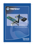
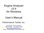
DIGIBAR-Pro
PROFILING SOUND VELOCIMETER
OPERATION MANUAL
Software Version 1.XX
Odom Hydrographic Systems, Inc.
1450 Seaboard Avenue
Baton Rouge, Louisiana USA 70810-6261
Telephone: (225) 769-3051 Fax: (225) 766-5122
[email protected]
http://www.odomhydrographic.com
07/02/01
1-1
TABLE OF CONTENTS
1 INTRODUCTION .................................................................................................... 1-3 1.1 Instrument Description ............................................................................................................................... 1-3 1.2 Theory of Operation .................................................................................................................................... 1-4 1.3 Features ........................................................................................................................................................ 1-5 1.3.1 GENERAL SPECIFICATIONS......................................................................................................... 1-5 1.4 Control Unit Front Panel Description ....................................................................................................... 1-6 1.5 Probe/Cable Description ............................................................................................................................. 1-7 2 OPERATION .......................................................................................................... 2-8 2.1 Pre-Operation Checks ................................................................................................................................. 2-8 2.2 Deployment .................................................................................................................................................. 2-8 2.3 Initial Configuration.................................................................................................................................... 2-9 2.4 Setup Menu Parameters ............................................................................................................................ 2-10 2.5 Performing a Velocity Cast ....................................................................................................................... 2-12 2.6 Acquire Parameters ................................................................................................................................... 2-14 2.7 Probe Cleaning........................................................................................................................................... 2-14 Press enter to........................................................................................................................................................ 2-14 3 INTERFACING ..................................................................................................... 3-16 3.1 Uploading Information to a PC ................................................................................................................ 3-16 3.2 Communication Menu Parameters .......................................................................................................... 3-16 4 WARRANTY ........................................................................................................ 4-20 Appendix 1 ............................................................................................................................................................. 4-21 Downloading Examples using Digibar Pro Log 2.1:........................................................................................... 4-21 Appendix 2 ............................................................................................................................................................. 4-27 Quality Assurance Check...................................................................................................................................... 4-27 07/02/01
1-2
LIST OF FIGURES
Figure 1. 1.................................................................................................................................................................. 1-3
Figure 2. 2.................................................................................................................................................................. 1-6
Figure 3.1..................................................................................................................... Error! Bookmark not defined.
07/02/01
1-2
1 INTRODUCTION
The Operation manual contains information required to operate and field test the DIGIBAR-PRO
Model 1200 hand-held sound velocimeter.
1.1
Instrument Description
DIGIBAR-PRO is a third generation velocimeter employing the sing-around method of sound
velocity determination. Building on more than 15 years of experience in manufacturing
velocimeters used in calibrating echo sounders, this latest version of the DIGIBAR-PRO is
tailored for the advanced applications practiced in the field today. The unit not only samples,
displays, and stores values for the speed of sound in water, but it also ties each collected value to
a precise depth. Built for real world use, the rugged instrument is made up of a hand-held
controller (splash rated to IP-65), a Kevlar reinforced cable (with a 400 lb. breaking strength
rating), and a marine grade stainless steel probe.
Figure 1. 1
DIGIBAR-PRO
Profiling Sound Velocimeter
07/02/01
1-3
The velocity of sound and depth values displayed on the DIBIGAR-PRO front panel are
measured, stored in memory, and displayed by the system's internal microprocessor and its
associated circuitry. The processor applies Del Grosso's formula to the sing-around frequency
calibration constants, yielding accurate and traceable velocity results. The addition of a pressure
sensor to the velocimeter probe lends new versatility to the instrument. Calibration of single
beam echo sounders using the earlier model DIGIBAR was always easier to accomplish than the
traditional "bar check" method of velocity determination and that utility has been maintained in
the new DIGIBAR-PRO. The addition of precise profiling capabilities to the new model means
that multi-beam echo sounders are now able to utilize the output of the DIGIBAR-PRO directly
in their critical ray-bending calculations.
1.2
Theory of Operation
Mounted near the end of the sampling probe is the high frequency "sing-around" transducer and
its associated reflector. This precisely spaced pair is used to measure the velocity of sound in
water by transmitting and receiving a signal across their known separation distance. After the
first transmission, the received echo is gated and introduced into the feedback loop of an
oscillator that re-triggers the transmitter and begins the cycle again. The frequency resulting
from this regenerative feed-back loop is determined by the distance the signal travels (transducer
to reflector and back) and is directly proportional to the velocity of propagation of the sound
pulse through the measured medium (in this case water). This method of direct sampling means
that all factors that influence the speed of sound, including salinity, pressure, and temperature,
are taken into account. An embedded RISC processor in the probe digitizes the sing-around
frequency and depth information, sending that data along with temperature and calibration
constants in ASCII format via a 2 wire current loop up the cable to the hand-held control unit at
a 10 Hz rate.
In the control unit, another microprocessor accepts data from the probe, converting the frequency
information to sound velocity, and the pressure data into depths, storing them in internal
memory. In addition to converting both values to usable units, the control unit provides an easy
to use operator interface. The multi-line display and system of menus guide the operator through
the steps required to complete a successful velocity cast. Other features of the control unit
include, data storage space, interfacing circuitry for transmission of collected data to a PC, and a
power source (three Alkaline C-cells) for driving both the probe and its own internal circuitry.
The velocity and depth information collected from up to 10 casts can be stored in DIGIBARPRO's internal memory. The average velocity value of each cast can be calculated, or the entire
velocity profile of the cast can be up-loaded to a PC, in spreadsheet format, for subsequent use in
ray-bending calculations.
07/02/01
1-4
1.3
Features
The following is a list of standard DIGIBAR features:
•
•
•
•
•
•
•
•
•
•
•
•
Velocity and depth displayed in feet or meters
Automatic storage of up to 10 complete casts
Computed average of all stored velocity samples in one cast or
Up-loading of cast data to an external computer in spreadsheet format
Review and editing of all stored cast data
Durable sealed hand-held control unit
4 line x 40 character Transflective LCD display for readability in bright sunlight
Low drag high breaking strength cable
Compact probe
Low battery indicator
Operates on 3 standard "C" cell batteries
Operates in fresh, brackish, or salt water
1.3.1 GENERAL SPECIFICATIONS
Velocity / Depth Probe
Sing-Around Frequency:
Communications:
Temperature Range:
Sample Rate:
Depth Sensor Accuracy:
Dimensions:
Weight:
Depth Rating
11 kHz
RS485, 19.2 k Baud
4° to 30° C Typical
10 Hz
> 1.0 ft (31.0 cm)
14.7l x 2.0d inches (37.3l x 5.0d cm)
4.0 lb. (1.8kg)
NTE 100m
Hand-held Control Unit
Velocity Range:
Resolution:
Accuracy:
Power Requirement:
Communications:
Dimensions:
Weight:
4595 – 5250 ft/sec (1400 – 1600 m/sec)
0.1 ft/sec (0.1 m/sec)
± 1.0 ft/sec (±0.3 m/sec)
Three "C" cell Alkaline Batteries
RS232, Selectable Baud Rate
11.4l x 5.5w x 3.7d inches (29.0l x 14.0w x 9.4d cm)
2.6 lb. (1.2 kg)
Cable
Construction:
Diameter:
Breaking Strength:
4 Conductor, Kevlar reinforced, and Polyethylene jacket
0.27 in. (6.9mm)
400 lb. (182 kg)
07/02/01
1-5
1.4
Control Unit Front Panel Description
All controls on the unit’s front panel as well as the LCD display are sealed to prevent water
damage. As seen in Figure 1.2 below, the simple scheme of left, right, up, and down arrows,
plus enter and escape keys, coupled with the scrolling display menu system makes the
DIGIBAR-PRO quite straight-forward and easy to operate.
Figure 2. 2
DIGIBAR-PRO
Profiling Sound Velocimeter
Key Pad Illustration
07/02/01
1-6
1.5
Probe/Cable Description
The velocimeter/depth probe, in its standard configuration, is connected to the hand-held control
unit via a low drag (0.27 in. (7mm)), 60-foot (20 m) long, multi-conductor cable. The cable is
designed to withstand the rigors of long use in the field, having an internal Kevlar strength
member and a heavy polyethylene outer jacket. Additional weight may be added to the cable (up
to 25lbs. total) in order to depress the probe in high current conditions. Alternative cable lengths
of up to 100m (328 ft.) can be supplied upon request.
Although great care was taken in the design of the probe to assure maximum strength and
durability, it should not be dropped or otherwise subjected to unusual mechanical stress. All
components in the acoustic signal path are of stainless steel alloys, selected for their corrosion
resistance and low coefficient of thermal expansion. In order to minimize the possibility of
corrosion damaging the probe and cable deterioration, they should be washed down in fresh
water and allowed to dry before storage.
The velocimeter/depth probe is made up of the following 9 individual components:
•
•
•
•
•
•
•
•
•
Cable penetrator (plus cable strain relief, PC board, and O-rings)
Probe body (SS tube)
Transceiver board
Processor board
Velocity transducer
Pressure transducer
Transducer penetrator (plus O-rings)
Spacers (3 ea.)
Reflector plate
Should the DIGIBAR cable require replacement, the penetrator can be removed at the probe and
the cable disconnected at the control unit. Replacement of the cable does not require
recalibration of the instrument. However, removal or replacement of other probe components
should not be attempted since their position and or settings are generally critical to calibration.
07/02/01
1-7
2 OPERATION
Both the membrane switches and display on the control unit's front panel are sealed, and all
openings in the body of the housing are gasketed in order to prevent water damage. However, it
is a good idea to minimize the unit's unnecessary exposure to the elements in order to prevent
possible long-term damage due to corrosion. To prevent unnecessary battery drain, the unit is
powered down automatically after 10 minutes of inactivity (no switches are pressed).
2.1
Pre-Operation Checks
The probe should be inspected before deployment to assure that no foreign materials are present
in the acoustic path. The face of the transducer and the reflector plate should be clean and free of
debris. The probe can be cleaned with mild soap and water without damage, should the need
arise.
2.2
Deployment
Probe deployment is as simple as lowering the unit over the side to the desired depth, and then
retrieving the unit. However, a few operational considerations should be kept in mind while
making velocity casts.
Safety should be a primary concern of the operator! The probe should never be dropped into
areas where it may become entangled in underwater obstructions. Deployment of the probe in
the vicinity the ship's propellers is not only unwise, due to the risk of damage to the equipment,
but it is extremely unsafe as well.
When deploying the unit in bodies of water with little or no current, air bubbles can become
attached to the face of the probe or the reflector plate. Any accumulation of bubbles will disrupt
the operation of the velocimeter. However, they can be removed easily by gently swinging the
probe back and forth under the surface of the water.
07/02/01
2-8
2.3
Initial Configuration
Power ON
Depress and hold the power button for 3 seconds.
The display will show the Header Screen for 1 second:
Digibar Pro v x.xx
S/n DB98xxx
Odom Hydrographic
Systems, Inc.
The Header Screen will disappear and be replaced by the Main Menu. The initial cursor
position is opposite the Acquire sub menu.
NOTE: Before starting the first velocity cast the conditions or parameters of the cast should be
examined and adjusted as necessary.
Main Menu
Acquire
Review
Setup
Comm
Battery/Probe Power
Version
From the Main Menu select Setup. Press the appropriate up and down arrows until the cursor
(arrowhead) is positioned opposite Setup. Press the Enter key to display the Setup Menu.
Setup Menu
07/02/01
Log Basis
Depth interval
Time interval
Units
Surface Detect
Store Cast Data
DepthAvg.
VelAvg.
Time
Date
Use Default Setup
Simulator
Probe Constants
2-9
Depth
0.5
1
Meters
off
Yes
4
1
11:27:00
09/16/99
off
2.4
Setup Menu Parameters
Log Basis: Velocities can be logged in the control unit based on either depth or time. The
usual method of producing a velocity profile is to log velocities based on depth. In
order to accomplish this task, place the arrowhead cursor on Log Basis and press the
Enter key. One should now note a blinking cursor over the last character of the
parameter value. Press the UP or Down arrow keys. Note that pressing either key
causes the value to toggle between Depth and Time. Pressing the Enter key with
either Depth or Time displayed will cause that value to be selected as the current Log
Basis.
Depth Interval: Should Depth be chosen as a Log Basis value, then the Digibar will log
velocities based on changing depths. The Depth Interval parameter allows the
operator to determine how often and at what depth the velocity is logged. For
instance, if the operator selects a depth interval of 1, then every time the depth
measured by the probe increases or decreases by 1 unit (either feet or meters as set by
the Units value) a new velocity will be stored in memory. In addition, the depth
value, which triggered the measurement, is stored. Both pieces of data are logged on
the trip down to the bottom of the cast and on the way back up toward the water's
surface at every selected interval. This duplication can serve as a confirmation of the
accuracy of the profile.
Time Interval: Time based logging works in much the same way as does depth interval,
except of course that the measurement cycle is based on a preset interval of time (1 to
999 seconds) rather than a cycle based on depth. This function would normally be
reserved for logging at a fixed depth over a period of time where changes in velocity
are expected to occur due to circumstances not necessarily associated with changing
depth (flow, turbidity, dissolved minerals, etc.).
Units: This parameter enables the operator to change measurement units between meters and
feet to suit the requirements of the survey. Should measurement units of feet be
selected, then all results, including velocity and depth will be displayed in feet. All
measurement results will, of course be displayed to the nearest 0.10 meters should
that parameter value be selected.
Surface Detect: When selected, this parameter is intended to allow the probe to
automatically end a cast once it detects atmospheric air pressure. The Surface Detect
parameter has not been implemented in version 1.00 firmware.
Store Cast Data: This parameter gives the operator the option of either storing velocity
and depth in the Digibar's internal memory or simply displaying that information.
The only two choices are Yes or No.
DepthAverage, VelocityAverage: Digibar-Pro gives the operator the option of either
averaging a number of individual measurements in the hope of minimizing the
07/02/01
2-10
influence of single bad data points, or storing one data point at each predetermined
measurement interval. The results of a cast using a number of averaged velocities for
instance would be a somewhat "smoother" profile, which reacts less rapidly to
spurious changes as the number of averaged data points is increased. The default
value for depth is 4 (four depths are averaged to arrive at the measurement depth) and
velocity is 1 (the most recent velocity at the measurement depth is stored).
Time, Date: The unit's internal clock / calendar keeps track of the current time and date for
record keeping purposes. During a velocity cast, both the time and date of each
measurement is stored in the system's memory. Some formats require time and date in
the header information, while others require a time and date to be associated with
each data point. Since this information is always available in the Digibar, uploading
velocity profiles in several different formats is possible.
Use default setup: This parameter provides an easy way to return the unit to the standard
factory set parameter values. Pressing the ENTER key with Use default setup
displayed results in the warning message "Press enter to reset params to factory
defaults, any other key to cancel".
Simulator: The system's internal simulator provides a handy method of both displaying the
operation of the system and of testing its interfacing capabilities. Once selected, the
unit goes through the normal steps required for a velocity cast, however, no probe
need be connected in order to complete the simulated cast.
Probe Constants:
This parameter is intended for use in troubleshooting a suspect
velocity probe only. Probe constants are associated with the calibration of the
velocimeter transducer and should be adjusted only under the direct supervision of an
Odom engineer.
Once the operator is satisfied that the parameters of the cast are properly configured, then press
Esc to return to the Main Menu.
07/02/01
2-11
2.5
Performing a Velocity Cast
From the Main Menu, position the arrowhead cursor opposite the Acquire parameter and press
the Enter key. This will put the unit in the velocity acquisition mode.
Acquire Menu
Cast
Memory/casts
Depth
Velocity
View All
Start
%100/1
1.0
5,000.0
Cast: Pressing the Enter key with the arrowhead cursor positioned opposite the Cast
parameter initiates velocity and depth data acquisition. The following screen will be
displayed:
Lower probe to calibration mark and hit
Enter to cast or any
other key to cancel
Lowering the probe to the calibration depth mark on the cable and pressing the Enter
key tells the probe's microprocessor to calibrate the depth sensor. This step
compensates for changes in atmospheric pressure and improves the accuracy of the
depth data.
Once the cast has begun, all values displayed are real time information. As the probe
is lowered, the depth value will increase and the velocity value will change as the
speed of sound varies. Lower the probe to the depth required by the survey and then
retrieve it. The DIGIBAR-Pro will continue to gather depth and velocity information
on the trip to the surface just as it did on the way down to the calibration depth.
Please NOTE: In order to assure the accuracy of the Cast which is underway, do not
attempt to begin any other function of the unit, such as changing units or running the
Test PC routine, while the Cast is still in progress.
07/02/01
2-12
Once the velocity/depth probe has been lowered to the designated depth and then retrieved,
position the cursor opposite the Cast parameter and press the Enter key in order to stop data
collection.
Cast
Memory/casts
Depth
Velocity
View All
Acquire Menu
Stop
%100/1
0.5
4,960.0
As soon as data collection is terminated, the Review screen will be displayed.
Date and Time at start of cast
Cast #
Average Velocity of
entire cast (all samples)
1 09/16/99 12:05:02
AV 1500.0m/s MD 50m
D 11.0 Vel 1300.0
D 12.0 Vel 1301.3
Depth of Sample
Maximum Depth reached
during current cast
Velocity of Sample
The Review screen gives the operator the opportunity to scroll through all of the individual
records taken in the latest cast. This is not intended to be a full editor of long or deep profiles,
but rather a quick way to look at individual readings, comparing each to its neighbors to confirm
that no individual sample seems to be very far out of bounds. We suggest that the entire cast be
uploaded to spreadsheet format if more extensive analysis or editing is required
Should an obviously bad sample be encountered, pressing the Enter key with the record selected
(arrowhead cursor opposite the record) will start the deletion process.
1 09/16/99 12:05:02
AV 1500.0m/s MD 50m
D 11.0 Vel 1300.0
D 12.0 Vel 1301.3
The deletion confirmation screen will appear as soon as Enter is pressed.
07/02/01
2-13
Press enter to
DELETE this record,
Or any other key to
cancel
Pressing the Enter key a second time will delete the record from the cast.
.
2.6
Acquire Parameters
In the Acquire mode, several parameters are displayed to assist in judging the quality of the cast
data and for managing data storage.
Memory/casts: This parameter displays the percent of memory available for cast data
storage, and the number of casts collected. The amount of memory available should
alert the operator to the possibility of running out of memory once the number of
stored casts begin to approach the upper limit of 10. Casts can be deleted once the
data has been uploaded to a computer in order to free up memory space.
Depth: Moving the cursor to the Depth position and pressing Enter results in only the realtime depth value being displayed in large (multi-line) characters in the display.
Pressing any key will cause the display to revert to the Acquire Menu.
Velocity: Pressing the Enter key with Velocity selected will result in the speed of sound
being displayed in large characters. Pressing any key will cause the display to revert
to the Acquire Menu.
View All: Selecting View All causes the display to show both the velocity and depth data on
a line by line basis (3 lines displayed at a time) scrolling up from the bottom of the
screen.
The same information shown in the View Cast screen can be accessed later by going to the Main
Menu and selecting Review. Using the arrow keys, position the cursor opposite Review and press
the Enter key.
Acquire
Review
Main Menu
Setup
Comm
Battery/Probe Power
2.7 Probe Cleaning
Version
After each operation, the probe should be checked for foreign matter lodged within the sampling
chamber. In addition, in order to ensure long term accurate measurements, the probe should be
07/02/01
2-14
rinsed with fresh water and dried after each cast. This will minimize the possibility of corrosion
affecting the function of the probe.
07/02/01
2-15
3 Interfacing
3.1
Uploading Information to a PC
Main Menu
Acquire
Review
Setup
Comm
Battery/Probe Power
Version
After completing a Cast, it will often be desirable to upload the results to a PC in spreadsheet
format for further processing or record keeping. To do so, select Comm in the main menu and
press Enter. The screen shown below will be displayed.
Output Cast
Comm menu
3.2
All
1,2,etc.
Output Type
CSV
SVP16
NMEA
WGEO
HYPACK
SOUNDER
Output During Yes
No
Baud rate
19200
9600
4800
Test PC
Test probe
Communication Menu Parameters
Output Cast: Listed after this parameter are the numbers for each of the casts stored in the
unit's memory (from 1 to a possible 10). Selecting All and pressing the Enter key
will result, as the name implies, in all of the casts being output to an external
computer. Selecting individual casts by number tells the unit to output only the
results of the selected cast. NOTE: Please read the section labeled Annotating the
Echo Sounder Chart Automatically, later in this chapter.
07/02/01
3-16
Output Type: The choice of 5 different output formats can be made using the this
parameter.
CSV: Selecting the CSV format option results in the unit sending ASCII data in the
following arrangement:
# CAST 1 Meters Records 3
09/16/99, 11:33:17, 1503.0,1.5,16.0
09/16/99, 11:33:17, 1503.4,2.0,15.0
09/16/99, 11:33:17, 1503.9,2.5,14.0
The CSV cast data begins with the header line showing the # of the Cast (#1 in
the example), followed by the measurement unit (meters in this example), and by
the number of records in the file (in this example only 3 individual samples were
stored). Once the header line is complete, each individual record is listed
beginning with the date, followed by time, velocity, depth, and probe temperature.
SVP16: In this configuration, the Digibar Pro emulates the output string of the SVP
16 sound velocity profiler.
"CALC, DBxxxx, 09/16/99, 1, Meters"
OHSI Sound Velocity Profiler S/N DBxxxx
Date: 99259 Time: 1133
Depth Offset (M): 0
Depth (M) Velocity (M/S) Temp (C)
1.5 1503.0 8.5
2.0 1504.2 9.0
2.5 1504.4 9.0
NMEA: This output string complies with the sentence structure of the NMEA
standard for manufacturer's proprietary strings.
$PSSV, 1503.0, 1.5,M*54 (for Units = Meters)
$PSSV, 4860.0, 4.0,F*52 (for Units = feet)
The "$" character denotes start of sentence.
"P" Proprietary sentence ID
"SSV" Manufacturer's mnemonic code
"," The comma delimiter character starts each field except address and checksum
<ccc> Velocity, Depth, Measurement units data fields
"*" Checksum delimiter
<Checksum field> The absolute value calculated by exclusive-OR'ing the 8 data
bits of each character in the sentence between, but not including the "$" and "*".
<CR><LF> End of sentence
07/02/01
3-17
WESTGEO: This sentence complies with the requirements of the current WG-1100
velocimeter output string.
634 01503
635 01503
636 01504
The string is composed of a 3-digit sequential event number, followed by a space,
and then 5 characters of velocity data. Each record is delimited by a <CR><LF>.
Sounder: When the Sounder output string is selected, the Digibar sends a <CTRL>A
followed by "Digibar Pro 9999 (Serial No.) 11/08/99 10:45:20 AvgVel 1500.2
(m/s, f/s) MaxDepth 100 (m or ft.).<CTRL>D. NOTE: See annotating the Echo
Sounder chart automatically in a later section.
Hypack: Selection of the Hypack SV Format causes the Digibar Pro to output a
header: FTP New followed by the cast data in two columns (depth velocity). All
velocity values are in meters/second.
FTP New
002.5 1500.0
003.0 1503.1
003.5 1503.2
Output Cast
Comm Menu
All
1,2,etc.
Output Type
CSV
SVP16
NMEA
WGEO
HYPACK
SOUNDER
Output During No
Yes
Baud rate
19200
9600
4800
Test PC
Test probe
Output During: In the majority of operating circumstances, the Hand-held control unit will
not be connected directly to a computer or other logging device. It will simply be
used as designed as a portable, completely self-contained profiling system. However,
the option does exist for echoing the data out the serial port for logging on both the
07/02/01
3-18
DIGIBAR-PRO control unit and an external computer. Selection of Yes under
Output During will cause this to happen.
The output string will be composed of the following:
02/28/02,08:56:02,1484.9,0.0,25.0
MM/DD/YY, time, velocity, depth, temperature
In most cases, portable operation will not require data to be output until the entire
cast, or a number of casts, are collected. In this case, Output During - No should be
selected.
Baud rate: Select the appropriate rate to match the logging computer's serial port. The
default baud rate is 19.2 kbps. with no parity, 8 data bits, 1 start bit, and 1 stop bit.
Test PC: If selected, the control unit will display any characters seen on its serial input, and
echo those same characters out its serial output.
Test probe: Causes raw data from the velocity / depth probe to be displayed and sent out
the serial port.
Marking the Echo Sounder Chart Automatically:
A convenient feature of the Digibar Pro is the capability of the unit to transfer data directly from
the hand held control unit to either an Echotrac MKII or a Hydrotrac's chart record. This feature
can be used to confirm the velocity value used during a survey and to log the time and date of
each velocity cast. The procedure is described below:
1) In the Main Menu, Select the Comm parameter (move the cursor to the position
opposite Comm and press Enter). Selecting the Comm parameter causes the Comm
submenu to be displayed.
2) Move the cursor to the position opposite Output Type. Scroll through the
parameters until SOUNDER appears and press Enter.
3) Confirm that the parameter labeled Output During is OFF, and that the Baud Rate
displayed by the Digibar Pro is consistent with the baud rate of the Hydrotrac or
MKII to be marked (9600 by default).
4) Connect the standard RS-232 serial cable supplied with the Digibar Pro to the Serial
Port. Using the special Digibar Pro to Echotrac/Hydrotrac serial port adapter cable,
connect the Digibar Pro to the Com1 serial port of the MKII or the Hydrotrac. Note:
Establishing communication between the Digibar Pro and the MKII may require that
an existing serial port connection (to the data acquisition system for example) be
removed.
5) Once the cable is connected between the Echotrac/Hydrotrac Com 1 port, move the
cursor to the Output Cast parameter. Select the cast that is to be printed on the
07/02/01
3-19
chart, and press the Enter key. This will cause the Echotrac/Hydrotrac to print the
information contained in the Sounder string on the unit's chart. Please note that the
actual velocity used by the sounder will not be changed as a result of this process!
Since the sound velocity value established in the echo sounder is most often
established by calibrating using the bar check method, changing the actual velocity in
the echo sounder is left up to the operator.
4 Warranty
The manufacturer warrants all equipment to be free from defect in materials or workmanship for
a period of one (1) year from date of shipment. All necessary adjustments, repairs, or
replacement of equipment manufactured by Odom Hydrographic Systems, Inc. not occasioned
by accident, misuse or modification, shall be made by Odom at its own expense during the
period of the warranty. Items for repair under terms of the warranty must be returned freight
prepaid by the customer to Odom's factory in Baton Rouge, La. U.S.A. The warranty applies to
the original purchaser only.
07/02/01
4-20
DigibarPro Version 1.07
Appendix 1
Downloading Examples using Digibar Pro Log 2.1:
HYPACK compatible velocity tables:
Downloading a velocity cast from the hand held control unit into HYPACK assumes that a couple of
conditions are satisfied. Namely, that velocities are either converted to or are measured in meters/second,
and that the associated data file ends in the file extension ".vel". In addition, HYPACK assumes a "oneway" cast, that is, the cast begins near the surface of the water and ends at the maximum depth. Use of a
two-way or round-trip cast remains a good idea for confirming velocities, however one set of data
(usually the retrieval data) should be edited out of the cast file before attempting to use the file in
HYPACK.
1. Collect a single direction velocity profile (generally surface to maximum depth) in the same
measurement units as those used for the survey (feet or meters).
2. Note the cast number and edit the individual samples using the Review parameter of the
DigibarPro. Delete any obvious bad velocities from the cast. Please note that often the last
velocity taken will be at or near the bottom and consequently may be corrupted by bottom
sediment in the sampling chamber.
3. Select the Comm menu on the DigibarPro control unit and confirm the Baud Rate is set to
19.2kbs.
4. Connect the DigibarPro serial cable to an active communications port on the data acquisition
PC. Launch the program DigibarPro Log 2.1. This program is supplied free of charge
with each DigibarPro unit and is available for downloading from our website.
5. On the data acquisition PC, click on the Setup tab in Digibar Pro Log, and confirm that:
a. The appropriate Com Port on your PC is displayed (Com 1, Com 2, etc.)
Appendix1
4-21
10/27/08
DigibarPro Version 1.07
b. The box next to Com Port is checked and no checks remain in the boxes next to the
"direct to probe" or "simulator" buttons.
6. Click on the Logging tab. The default file name is cast00.csv. Please note that if the
operator chooses to change nothing from the default configuration, then the file to be
downloaded (in most cases) will be stored at C:/Program Files/Digibar Pro/cast00.csv.
7. Click the Browse button and rename the file with a more descriptive name, perhaps one
including the date and time, before proceeding. This aids in tracking data from particular
casts later on.
Appendix1
4-22
10/27/08
DigibarPro Version 1.07
8. Click on the box next to the Begin Cast Download button and enter the # of the particular
cast in the DigibarPro control unit you wish to download (1 thru 10).
9. Click the Begin Cast Download button. Note that the status line at the bottom of the
Logging tab will show "Downloading cast # to log file", followed by "Download
complete". In addition, the circle in the lower right hand corner of the screen will change
colors while data is being transferred.
Appendix1
4-23
10/27/08
DigibarPro Version 1.07
10. Click on the Graph tab. Observe that the graph of the downloaded data looks appropriate
for the cast conditions.
11. Click on the Grid tab. The grid tab allows the operator to observe and edit the collected data
in spreadsheet format. Once the operator is satisfied with the veracity of the data, click the
Save Button. At this point a windows menu titled "Save Cast File" will be displayed. In
this window, the operator will be given the opportunity to save the file with a different file
name, to determine the destination directory, and to save the file as a different file type (Cast
Files (*.CSV), Hypack Files (*.VEL), or All Files (*.*). Important: In order to save the cast
in the format required by Hypack, the operator must choose the File Type "Hypack Files
(*.VEL)" at this point. Otherwise, Hypack will be unable to read the data. Note: it is also a
good idea to save the file into the Coastal/Datum directory (for Hypack Version 8.9).
Appendix1
4-24
10/27/08
DigibarPro Version 1.07
An interesting observation: In Hypack applications, if velocity data is collected in feet/sec., the data will
automatically be converted to meters/sec. by Digibar Pro Log once the operator tells the program to save
the file as a *.VEL file (Hypack compatible file). Depths continue to be stored in feet, but all velocities
are stored in meters/sec. You can monitor the results of this conversion in the Coastal/Datum directory by
selecting Editing, Sound Velocity in Hypack.
Digibar File Transfer Protocol
Downloading files in the DigibarPro format (each record includes date, time, velocity and depth, ending
with the ".csv" extension) is accomplished in the much the same manner as illustrated in steps 1 through
11 above. In Step 11, where the operator is instructed to choose "Hypack Files" the operator should
choose the standard spreadsheet compatible (Cast Files (*.CSV)) file type.
1. Collect a velocity profile (either one-way surface to maximum depth, or round-trip) in the
same measurement units as those used for the survey (feet or meters).
2. Note the cast number and edit the individual samples using the Review parameter of the
DigibarPro. Delete any obvious bad velocities from the cast. Please note that often the last
velocity taken will be at or near the bottom and consequently may be corrupted by bottom
sediment in the sampling chamber.
3. Select the Comm menu on the DigibarPro control unit and confirm the Baud Rate is set to
19.2kbs.
4. Connect the DigibarPro serial cable to an active communications port on the data acquisition
PC. Launch the program DigibarPro Log 2.1. This program is supplied free of charge
with each DigibarPro unit and is available for downloading from our website.
5. On the data acquisition PC, Click on the Setup tab in DB Pro Log, and confirm that:
a. The appropriate Com port on your PC is displayed (Com 1, com 2, etc.)
b. The box next to Com port is checked and no checks are in the boxes next to "direct to
probe" or "simulator" buttons.
6. Click on the Logging tab. The default file name displayed is cast00.csv. Please note that if
the operator chooses to change nothing from the default configuration, then the file to be
downloaded (in most cases) will be stored at C:/Program Files/Digibar Pro/cast00.csv.
Should the operator choose to change the file name or destination directory, then click the
Browse button and rename the file with a more descriptive name (perhaps one including the
date and time) before proceeding. Making more descriptive file names aids in tracking data
from particular casts later on.
7. Click on the box next to the Begin Cast Download button and enter the # of the particular
cast in the DigibarPro control unit you wish to download (1 thru 10).
8. Click the Begin Cast Download button. Note that the status line at the bottom of the
Logging tab will show "Downloading cast # to log file", followed by "Download
complete". In addition, the circle in the lower right hand corner of the screen will change
colors while data is being transferred.
9. Click on the Graph tab. Observe that the graph of the downloaded data looks appropriate
for the cast conditions.
10. Click on the Grid tab. The grid tab allows the operator to observe and edit the collected data
in spreadsheet format. Once the operator is satisfied with the veracity of the data, click the
Save Button. At this point a windows menu titled "Save Cast File" will be displayed. In
this window, the operator will again be given the opportunity to save the file with a different
file name, to determine the destination directory, and to save the file as a different file type.
Appendix1
4-25
10/27/08
DigibarPro Version 1.07
Once this step is completed, additional editing or plotting of the sound velocity profile can be
accomplished using specialized outside software.
The important fact here is that all of the data from the cast is easily and quickly transferred to a standard
PC in a common spreadsheet readable format without the need of hand operations or translation from
"scientific units" to depths and velocities. Another method of achieving this without the use of the
Digibar Pro Log program is to transfer the data using a standard "Terminal Emulation" program such as
ProLog or HyperTerminal.
Interface Cable Pin Out:
Cable Part Number 2300-0033-0000
MS3116J10-6P
Pin
A
B
C
Appendix1
Signal
Data Out
Data In
Shield
DE-9S
Pin
2
3
5
4-26
10/27/08
DigibarPro Version 1.07
Appendix 2
Quality Assurance Check
To receive the utmost reliability and accuracy from your Digibar Pro, it is recommended that a quality
assurance check be performed periodically. This is a simple task that and will not take long to complete,
but will give the user a high level of confidence in the data collected.
You will need a bucket of water, the calibration certificate at the back of your Digibar Pro Operation
Manual, a reliable thermometer and the Digibar Pro. The use of a calibrated laboratory thermometer is
recommended, but is not necessary. Fill the bucket with fresh water. Choose the water temperature
between 4°C and 30°C. Obtain a copy of the Digibar Pro Calibration Certificate.
Immerse the Digibar Pro Sound Velocity Probe in the bucket containing the water of room temperature.
Acquire a sound velocity reading. Measure the temperature of the water. Find the temperature on the
Digibar Pro Calibration Certificate and read the value under the “RES-VEL” column. Compare the
reading to the actual value on the Digibar Pro. It should be within ± 1 meter/sec of the “RES-VAL” on
the certificate. It may be necessary to allow the transducer to become acclimated to the different water
temperature, so allow two to three minutes for the velocity value to settle. The following is an example of
a Digibar Pro Calibration Certificate.
STANDARD
DEL
GROSSO
H2O
03/01/2002
TEMP
VELOCITY
MEASURED
RES VEL
OBS-CAL
SERIAL#
98XXX
TEMP
VELOCITY
FREQUENCY
4.0
4.5
5.0
5.5
6.0
6.5
7.0
7.5
8.0
8.5
9.0
9.5
10.0
10.5
11.0
11.5
12.0
12.5
13.0
13.5
14.0
14.5
15.0
15.5
16.0
16.5
17.0
1421.62
1423.90
1426.15
1428.38
1430.58
1432.75
1434.90
1437.02
1439.12
1441.19
1443.23
1445.25
1447.25
1449.22
1451.17
1453.09
1454.99
1456.87
1458.72
1460.55
1462.36
1464.14
1465.91
1467.65
1469.36
1471.06
1472.73
Appendix1
MEASURED
RES VEL
FREQUENCY
1421.4
1423.7
1426.0
1428.3
1430.5
1432.7
1434.9
1437.0
1439.1
1441.2
1443.2
1445.3
1447.3
1449.3
1451.3
1453.2
1455.1
1457.0
1458.9
1460.7
1462.6
1464.3
1466.1
1467.9
1469.6
1471.3
1472.9
17.5
18.0
18.5
19.0
19.5
20.0
20.5
21.0
21.5
22.0
22.5
23.0
23.5
24.0
24.5
25.0
25.5
26.0
26.5
27.0
27.5
28.0
28.5
29.0
29.5
30.0
4-27
1474.38
1476.01
1477.62
1479.21
1480.77
1482.32
1483.84
1485.35
1486.83
1488.29
1489.74
1491.16
1492.56
1493.95
1495.32
1496.66
1497.99
1499.30
1500.59
1501.86
1503.11
1504.35
1505.56
1506.76
1507.94
1509.10
1474.6
1476.2
1477.9
1479.4
1481.0
1482.6
1484.1
1485.6
1487.0
1488.5
1490.0
1491.4
1492.7
1494.1
1495.4
1496.8
1498.1
1499.3
1500.6
1501.8
1503.1
1504.2
1505.4
1506.6
1507.8
1508.9
10/27/08
OBS-CAL
DigibarPro Version 1.07
Appendix1
4-28
10/27/08