1
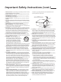
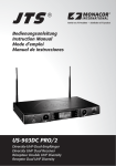
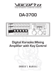
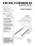
A7200
7 Channel Amplifier
7 CHANNEL AMPLIFIER A7200
Important Safety Instructions
Read this before operating your unit.
CAUTION
This symbol is intended to alert the user to the
presence of uninsulated "dangerous voltage"
within the product's enclosure that may be
of sufficient magnitude to constitute a risk of
electric shock to persons.
: TO REDUCE THE RISK OF
ELECTRIC SHOCK, DO NOT
REMOVE COVER (OR BACK).
NO USER-SERVICEABLE PARTS
INSIDE. REFER SERVICING TO
QUALIFIED SERVICE PERSONNEL.
WARNING
This symbol is intended to alert the user to
the presence of important operating and
maintenance (servicing) instructions in the
literature accompanying the appliance.
: TO REDUCE THE RISK OF FIRE OR ELECTRIC SHOCK,
DO NOT EXPOSE THIS APPLIANCE TO RAIN OR MOISTURE.
Note to CATV System Installer:
This reminder is provided to call the CATV system installerʼs attention to Article 820-40 of the NEC that provides
guidelines for proper grounding and, in particular, specifies that the cable ground shall be connected to the
grounding system of the building, as close to the point of cable entry as practical.
FCC INFORMATION
This equipment has been tested and found to comply with the limits for a Class B digital device, pursuant to Part 15 of
the FCC Rules. These limits are designed to provide reasonable protection against harmful interference in a residential
installation. This equipment generates, uses and can radiate radio frequency energy and, if not installed and used
in accordance with the instructions, may cause harmful interference to radio communications. However, there is no
guarantee that interference will not occur in a particular installation. If this equipment does cause harmful interference
to radio or television reception, which can be determined by turning the equipment off and on, the user is encouraged
to try to correct the interference by one or more of the following measures:
• Reorient or relocate the receiving antenna.
• Increase the separation between the equipment and receiver.
• Connect the equipment into an outlet on a circuit different from that to which the receiver is connected.
• Consult the dealer or an experienced radio/TV technician for help.
Caution: Any changes or modifications in construction of this device which are not expressly approved by the party
responsible for compliance could void the userʼs authority to operate the equipment.
FOR YOUR SAFETY
Units shipped to the U.S.A and Canada are designed for operation on 120 V AC only.
Safety precaution with use of a polarized AC plug.
However, some products may be supplied with a non polarized plug.
U.S.A.
CANADA
120 V
CAUTION
: To prevent electric shock, match wide blade of plug to wide slot, fully
insert.
ATTENTION
•
•
•
•
•
•
•
•
: Pour éviter chocs électriques, introduire la lame la plus large de la
fiche dans la borne correspondante de la prise et pousser jusquʼ au
fond.
Avoid high temperatures. Allow for sufficient heat dispersion when installed on a rack.
Keep the set free from moisture, water, and dust.
Do not let foreign objects in the set.
Handle the power cord carefully. Hold the plug when unplugging the cord.
Unplug the power cord when not using the set for long periods of time.
Do not obstruct the ventilation holes.
Do not let insecticides, benzene, and thinner come in contact with the set.
Never disassemble or modify the set in any way.
1
Important Safety Instructions (cont.)
1. Read Instructions - All the safety and operating instructions should
be read before the product is operated.
2. Retain instructions - The safety and operating instructions should
be retained for future reference.
3. Heed Warnings - All warnings on the product and in the operating
instructions should be adhered to.
4. Follow Instructions - All operating and use instructions should be
followed.
5. Cleaning - Unplug this product from the wall outlet before cleaning.
Do not use liquid cleaners or aerosol cleaners. Use a damp cloth for
cleaning.
6. Attachments - Do not use attachments not recommended by the
product manufacturer as they may cause hazards.
7. Water and Moisture - Do not use this product near water - for
example, near a bath tub, wash bowl, kitchen sink, or laundry tub; in
a wet basement, or near a swimming pool.
8. Accessories - Do not place this product on an unstable cart, stand,
tripod, bracket, or table. The product may fall, causing serious injury
to a child or adult, and serious damage to the product. Use only
with a cart, stand, tripod, bracket, or table recommended by the
manufacturer, or sold with the product. Any mounting of the product
should follow the manufacturerʼs instructions, and should use a
mounting accessory recommended by the manufacturer.
9. A product and cart combination should be moved with care. Quick
stops, excessive force, and uneven surfaces may cause the product
and cart combination to overturn.
10. Ventilation - Slots and openings in the
cabinet are provided for ventilation and to
ensure reliable operation of the product and
to protect it from overheating, and these
openings must not be blocked or covered.
PORTABLE CART WARNING�
The openings should never be blocked by
placing the product on a bed, sofa, rug, or
other similar surface. This product should not be placed in a built-in
installation such as a bookcase or rack unless proper ventilation is
provided or the manufacturerʼs instructions have been adhered to.
11. Power Sources - This product should be operated only from the
type of power source indicated on the marking label. If you are
not sure of the type of power supply to your home, consult your
product dealer or local power company. For products intended to
operate from battery power, or other sources, refer to the operating
instructions.
12. Grounding or Polarization - This product may be equipped with
a polarized alternating-current line plug (a plug having one blade
wider than the other). This plug will fit into the power outlet only one
way. This is a safety feature. If you are unable to insert the plug
fully into the outlet, try reversing the plug. If the plug should still fail
to fit, contact your electrician to replace your obsolete outlet. Do not
defeat the safety purpose of the polarized plug.
Alternate Warnings - This product is equipped with a three-wire
grounding-type plug, a plug having a third(grounding) pin. This
plug will only fit into a grounding-type power outlet. This is a safety
feature. If you are unable to insert the plug into the outlet, contact
your electrician to replace your obsolete outlet. Do not defeat the
safety purpose of the grounding-type plug.
13. Power-Cord Protection - Power-supply cords should be routed so
that they are not likely to be walked on or pinched by items placed
upon or against them, paying particular attention to cords at plugs,
convenience receptacles, and the point where they exit from the
product.
14. Outdoor Antenna Grounding - If an outside antenna or cable
system is connected to the product, be sure the antenna or cable
system is grounded so as to provide some protection against
voltage surges and built-up static charges. Article 810 of the
National Electrical Code, ANSI/NFPA 70, provides information with
regard to proper grounding of the mast and supporting structure,
grounding of the lead-in wire to an antenna discharge unit, size
of grounding conductors, location of antenna-discharge unit,
connection to grounding electrodes, and requirements for the
grounding electrode. See Figure 1.
Figure 1
Example of antenna grounding as per
National Electrical Code, ANSI/NFPA 70
ANTENNA�
LEAD IN�
WIRE
GROUND�
CLAMP
ANTENNA�
DISCHARGE UNIT�
(NEC SECTION 810-20)
ELECTRIC�
SERVICE�
EQUIPMENT
GROUNDING CONDUCTORS�
(NEC SECTION 810-21)
GROUND CLAMPS
NEC - NATIONAL ELECTRICAL CODE
POWER SERVICE GROUNDING�
ELECTRODE SYSTEM�
(NEC ART 250, PART H)
15. Lightning - For added protection for this product during a lightning
storm, or when it is left unattended and unused for long periods
of time, unplug it from the wall outlet and disconnect the antenna
or cable system. This will prevent damage to the product due to
lightning and power-line surges.
16. Power Lines - An outside antenna system should not be located in
the vicinity of overhead power lines or other electric light or power
circuits, or where it can fall into such power lines or circuits. When
installing an outside antenna system, extreme care should be taken
to keep from touching such power lines or circuits as contact with
them might be fatal.
17. Overloading - Do not overload wall outlets, extension cords, or
integral convenience receptacles as this can result in a risk of fire
or electric shock.
18. Object and Liquid Entry - Never push objects of any kind into this
product through openings as they may touch dangerous voltage
points or short-out parts that could result in a fire or electric shock.
Never spill liquid of any kind on the product.
19. Servicing - Do not attempt to service this product yourself as
opening or removing covers may expose you to dangerous voltage
or other hazards. Refer all servicing to qualified service personnel.
20. Damage Requiring Service - Unplug this product form the wall
outlet and refer servicing to qualified service personnel under the
following conditions:
a) When the power-supply cord or plug is damaged,
b) If liquid has been spilled, or objects have fallen into the product,
c) If the product has been exposed to rain or water,
d) If the product does not operate normally by following the
operating instructions. Adjust only those controls that are
covered by the operating instructions as an improper adjustment
of other controls may result in damage and will often require
extensive work by a qualified technician to restore the product to
its normal operation.
e) If the product has been dropped or damaged in any way, and
f) When the product exhibits a distinct change in performance - this
indicates a need for service.
21. Replacement Parts - When replacement parts are required, be
sure the service technician has used replacement parts specified
by the manufacturer or have the same characteristics as the
original part. Unauthorized substitutions may result in fire, electric
shock, or other hazards.
22. Safety Check - Upon completion of any service or repairs to this
product, ask the service technician to perform safety checks to
determine that the product is in proper operating condition.
23. Wall or Ceiling Mounting - The product should be mounted to a
wall or ceiling only as recommended by the manufacturer.
24. Heat - The product should be situated away from heat sources
such as radiators, heat registers, stoves, or other products
(including amplifiers) that produce heat.
2
Contents
Important Safety Instructions
READ THIS BEFORE OPERATING YOUR UNIT ___________________________________________ 1
Important Safety Instructions _____________________________________________________________ 2
System Connections _____________________________________________________ 4
CONNECTING SPEAKERS _____________________________________________________________ 7
SPEAKER PLACEMENT _______________________________________________________________ 8
Front Panel Controls _____________________________________________________
9
Operations _____________________________________________________________
9
Troubleshooting Guide ___________________________________________________
10
Specifications __________________________________________________________ 11
3
System Connections
• Please be certain that this unit is unplugged from the AC outlet before making any connections.
• Be sure to observe the color coding when connecting the preamplifier and speakers to this unit.
• Make connections firmly and correctly. Poor connections can cause loss of sound, noise or damage to the unit.
• For connections between this unit and the Boston Acoustics compatible preamplifier such as AVP7, refer to the AVP7's
manual.
Notes:
• Do not place other equipment on top of this unit so that the radiated heat can be properly dispersed.
• When installing in racks, etc., leave more than 12" (30cm) of space at the top.
1. DC TRIGGER IN
If this unit is connected to Boston Acoustics AVP7, connect
this jack to the “1” jack of DC TRIGGER OUTs of the AVP7
directly for system power control.
(For details, refer to the operating instructions of AVP7)
Note:
When making DC TRIGGER connection, you should use
the stereo mini cord supplied with this unit, not a mono mini
cord.
Sherwood pre amplifier P-965
1
2
DC TRIGGER OUT
2. GROUND TERMINAL
If necessary, connect this terminal to the “GND” of other
component.
3. AC INLET
To a wall AC outlet.
Plug the supplied AC input cord into this AC INLET and then
into the wall AC outlet.
To a wall AC outlet.
Note: Do not use an AC input cord other than the one
supplied with this unit. The AC input cord supplied is designed
for use with this unit and should not be used with any other
device.
4
4. CHANNEL INPUTS AND SPEAKER TERMINALS
INPUT
FRONT RIGHT
(4-8 )
INPUT
INPUT
SURROUND
BACK RIGHT
(4-8 )
SURROUND
RIGHT(4-8 )
INPUT
CENTER(4-8
)
INPUT
SURROUND
LEFT(4-8 )
INPUT
SURROUND
BACK LEFT
(4-8 )
INPUT
FRONT LEFT(4-8
)
• Be sure to connect speakers firmly and correctly, according to the channel (left and right) and the polarity(+ and -).
If the connections are faulty, no sound will be heard from the speakers, and if the polarity of the speaker connections is
incorrect, the sound will be unnatural and lack bass.
• Connect either the surround back left speaker or both of surround back speakers when using 6.1 or 7.1 channel surround
playback.
• To emphasize the deep bass sounds, connect a powered subwoofer to the preamplifier such as the Boston Acoustics AVP7,
not to this power amplifier. (For details, refer to the operating instructions of the preamplifier.)
• For installing the speakers, refer to “CONNECTING SPEAKERS” on page 6 and “SPEAKER PLACEMENT” on page 7.
• After installing the speakers, first adjust the speaker settings on your preamplifier according to your environment and speaker
layout. (For details, refer to the operating instructions of the preamplifier.)
CAUTION
• Be sure to use the speakers with the impedance of 4~8Ω.
• Do not let the bare speaker wires touch each other or any metal part of this unit. This could damage this unit and/or the speakers.
5
CONNECTING SPEAKERS
Connection using spade connectors
General connection using bare wire
1. Carefully strip about 3/8˝ (10mm) of insulation and
twist the wire tip.
1. Loosen the knob and insert the spade connector.
2. Loosen the knob and insert the wire.
2. Tighten the knob to fix the wire in place.
3. Tighten the knob to fix the wire in place.
Connection using banana plugs
1. Tighten the knob.
2. Insert the plug fully into the hole on the knob.
6
SPEAKER PLACEMENT
Ideal speaker placement varies depending on the size of your
room and the wall coverings, etc. The typical example of speaker
placement and recommendations are as follows:
1
3
2
4
5
■Front left, right speakers, and center speaker
• Place the front speakers with their front surfaces as flush with the
TV or the monitor screen as possible.
• Place the center speaker between the front left and right speakers
and no further from the listening position than the front speakers.
• Place each speaker so that sound is aimed at the location of the
listenerʼs ears when at the main listening position.
7
6
11
■Surround left and right speakers
Place the surround speakers approximately 40 inches (1 meter)
above the ear level of a seated listener on the direct left and right of
them or slightly behind.
■Surround back left and right speakers
• Place the surround back speakers at the back of the room, facing
the front at a closer distance to each other than the front speakers.
• When using a single surround back speaker, place it at the rear
center facing the front at a slightly higher position (0 to 10 inches)
than the surround speakers.
• We recommend installing the surround back speaker at a slightly
downward facing angle. This prevents the surround back channel
signals from reflecting off the TV or screen at the front center,
resulting in interference and making the sense of movement from
the front to the back less sharp.
8
10
1. TV or screen
2. Front left speaker
3. Subwoofer
4. Center speaker
5. Front right speaker
6. Surround left speaker
Surround speaker
9
7. Surround right speaker
8. Surround back left speaker
9. Surround back right speaker
10. Surround back center speaker
11. Listening position
Surround back
speaker
Front speaker
■Subwoofer
The subwoofer reproduces powerful deep bass sounds.
Place a subwoofer anywhere in the front as desired.
60 to 90 cm
■Notes:
• When using a conventional TV, avoid interference with the TV
picture by only using magnetically shielded front left, right, and
center speakers.
• To obtain the best surround effects, the speakers(except the
subwoofer) should be full range speakers.
7
Point slightly
downward
FRONT PANEL CONTROLS
OPERATIONS
j
k
To enter the standby mode.
• The STANDBY button lights up in amber. This means
that the unit is connected to an AC outlet and a small
amount of current is retained to support operation
readiness.
• To switch the power off, push the POWER switch
again. Then the power is cut off and the STANDBY
button goes off.
l
In the standby mode, turn the power on.
The STANDBY button lights up in blue, the unit
turns on and enters the operating mode. Sound can
be heard from the speakers in a few seconds.
In the operating mode, to enter the
standby mode.
■Note on system power control
If the DC TRIGGER connection is made between this
unit and the Boston Acoustics AVP7, this unit will be
switched between the standby mode and the operating
mode automatically each time the AVP7 is switched
between these modes.
(For details, refer to the operating instructions of
AVP7.)
The STANDBY button lights up in amber.
8
TROUBLESHOOTING GUIDE
If a problem occurs, run through the table below before sending your unit in for repair.
If the fault persists, attempt to solve it by switching the unit off and on again. If this fails to resolve the situation, consult your
dealer. Under no circumstances should you repair the unit yourself as this could invalidate the warranty!
PROBLEM
POSSIBLE CAUSE
REMEDY
No power
• The AC input cord is disconnected.
• Poor connection at AC wall outlet or the outlet
is inactive.
• Connect the cord securely.
• Check the outlet using a lamp or another
appliance.
No sound
• Speaker wires are disconnected.
• Incorrect connections between the
components.
• Incorrect operation of the preamplifier.
• Check the speaker connections.
• Make connections correctly.
No sound from one channel
• Speaker cords are connected incorrectly or
incompletely.
• Incorrect connections between the components.
• Defective speaker.
• Check the speaker connections and reconnect
them.
• Make connections correctly.
• Check the speaker and repair it or replace by
new one.
Excessive hum at normal
volume level
• The hum is induced from other components.
• Place the power amplifier away from the
preamplifier and the record player.
• Replace with new ones.
Distorted sound
• The power amplifier is overdriven.
• Too low impedance speakers are connected.
• Defective connection wires.
9
• Check the functions of the preamplifier to
assure it operates correctly.
• Decrease the volume on the preamplifier.
• Check the speakers and use the speakers
with the impedance of 4~8Ω.
SPECIFICATIONS
■Amplifier Section
Power output, stereo mode, 8Ω, THD 0.05%, 1kHz | 2 x 130W
4Ω, THD 0.05%, 1kHz | 2 x 220W
7-CH mode (full channel driven), 8Ω, THD 0.05 %, 20Hz-20kHz | 7 x 100W
4Ω, THD 0.05 %, 20Hz-20kHz | 7 x 150W
7-CH mode (only channel driven), 8Ω, THD 0.05 %, 20Hz-20kHz | 140 W/CH
4Ω, THD 0.05 %, 20Hz-20kHz | 240 W/CH
Total harmonic distortion, 8Ω, -6dB, 1kHz | 0.005 %
Intermodulation distortion
60Hz : 7kHz= 4 : 1 SMPTE, 8 Ω, 125W | 0.01%
Input sensitivity, 47kΩ | 1.0V
Signal to noise ratio, IHF “A” weighted
100w, 8Ω, 0dB | 120dB
1w, 8Ω, 0dB | 102dB
Frequency response, 20Hz–100kHz | +0, -1dB
Damping factor | 100
Power output, stereo mode, 8Ω, THD 0.02%, 1kHz | 2 x 122W
4Ω, THD 0.02%, 1kHz | 2 x 207W
7-CH mode (full channel driven), 8Ω, THD 0.02 %, 20Hz-20kHz | 7 x 95W
4Ω, THD 0.09 %, 20Hz-20kHz | 7 x 142W
7-CH mode (only channel driven), 8Ω, THD 0.02 %, 20Hz-20kHz | 135W/CH
4Ω, THD 0.02 %, 20Hz-20kHz | 200W/CH
Total harmonic distortion, 8Ω, -6dB, 1kHz | 0.005 %
Intermodulation distortion
60Hz : 7kHz= 4 : 1 SMPTE, 8Ω, 125W | 0.01%
Input sensitivity, 47kΩ | 1.0V
Signal to noise ratio, IHF “A” weighted
100w, 8Ω, 0dB | 120dB
1w, 8Ω, 0dB | 102dB
Frequency response, 20Hz–100kHz | +0, -1dB
Damping factor | 100
■General
Power supply | 120V~60Hz
Power consumption | 10A
Dimensions (W x H x D) | 17 3/8 x 7 3/4 x 17 3/4 inches (440 x 196 x 450mm)
Weight (Net) | 32kg (70.6 Ibs)
Note: Design and specifications are subject to change without notice.
10
Boston Acoustics, Inc.
300 Jubilee Drive
Peabody, MA 01960 USA
www.bostonacoustics.com
Boston, Boston Acoustics, and the Boston Acoustics
logo are registered trademarks of Boston Acoustics, Inc.
© 2005 Boston Acoustics, Inc. All rights reserved.
Specifications subject to change without notice
042-002293-0