1
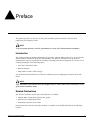
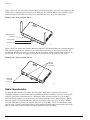
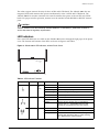
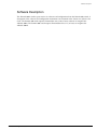
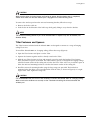
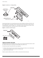
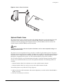
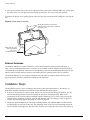
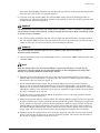
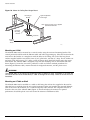
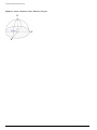
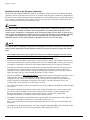
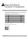
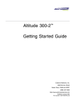
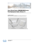
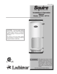
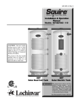
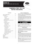
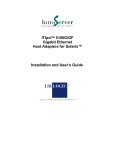
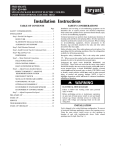
Altitude 300-2
Hardware Installation Guide
Extreme Networks, Inc.
3585 Monroe Street
Santa Clara, California 95051
(888) 257-3000
http://www.extremenetworks.com
Published: April 2005
Part number: 120175-00 Rev. 03
©2005 Extreme Networks, Inc. All rights reserved. Extreme Networks and BlackDiamond are registered trademarks of
Extreme Networks, Inc. in the United States and certain other jurisdictions. ExtremeWare, ExtremeWare Vista,
ExtremeWorks, ExtremeAssist, ExtremeAssist1, ExtremeAssist2, PartnerAssist, Extreme Standby Router Protocol, ESRP,
SmartTraps, Alpine, Summit, Summit1, Summit4, Summit4/FX, Summit7i, Summit24, Summit48, Summit300, Summit
Virtual Chassis, Altitude 300-2TM, SummitLink, SummitGbX, SummitRPS and the Extreme Networks logo are
trademarks of Extreme Networks, Inc., which may be registered or pending registration in certain jurisdictions. The
Extreme Turbodrive logo is a service mark of Extreme Networks, which may be registered or pending registration in
certain jurisdictions. Specifications are subject to change without notice.
All other registered trademarks, trademarks and service marks are property of their respective owners.
2
Contents
Preface
Introduction
Related Publications
Conventions
Chapter 1
Introduction
Overview
Chapter 2
7
Hardware Description
Altitude 300-2 Models And Connections
Radio Characteristics
LED Indicators
Package Checklist
7
7
8
9
10
Software Description
11
Hardware Installation
Mounting Options
Universal Mounting Bracket
T-Bar Fasteners and Spacers
Optional Antenna Shrouds
Optional Plastic Cover
External Antennas
13
13
15
16
17
18
Installation Steps
18
Placement
20
Mounting
Mounting
Mounting
Mounting
Mounting
Appendix A
Below a Hard Ceiling
Below a Hanging Ceiling
Above The Hanging Ceiling
on A Wall
on A Table or Shelf
20
20
21
22
22
Specifications
General Specifications
Altitude 300-2 Getting Started Guide
5
5
5
6
23
3
Contents
Maximum Number of Tunable Channels
Appendix B
Maximum Distance Table
Appendix C
Integrated Dual Band Antenna Pattern
Appendix D
Regulatory Compliance
23
Overview
General Compliance by Design
31
32
North America
United States - FCC Declaration of Conformity Statement
33
33
Conditions Under Which a Second party may replace a Part 15 Unlicensed Antenna
35
FCC RF Radiation Exposure Statement
Department of Communications Canada Compliance Statement
35
35
Japan
European Community
36
37
Declaration of Conformity with regard to R&TTE Directive of the European Union 1999/5/EC
Conditions of Use in the European Community
Permitted 5 GHz Channels for the European Community
European Spectrum Usage Rules
Declarations of Conformity
Certifications of Other Countries
4
37
38
39
39
41
42
Appendix E
Power Over Ethernet Connector Pin Assignments
Appendix F
Terminology
Altitude 300-2 Getting Started Guide
Preface
This preface provides an overview of this guide, describes guide conventions, and lists other
publications that might be useful.
NOTE
To ensure proper operation, read this guide before you install any Extreme Networks equipment.
Introduction
This guide provides the required information to install the Altitude 300-2 wireless port. It also contains
general product information about the Altitude 300-2. This guide is intended for use by network
administrators who are responsible for installing and setting up network equipment. It assumes a basic
working knowledge of the following topics:
• Local Area Networks (LANs)
• Ethernet concepts
• Simple 802.11 wireless LAN concepts
See the ExtremeWare Software User Guide for information about configuring an Extreme Networks
device.
NOTE
If the information in the Release Notes that shipped with your switch differs from the information in this
guide, follow the Release Notes.
Related Publications
The Extreme Networks wireless port documentation set includes:
• Altitude 300-2 Getting Started Guide (this guide)
• Unified Access Deployment Guide
• ExtremeWare Software User Guide
Documentation for Extreme Networks products is available on the World Wide Web at the following
location:
Altitude 300-2 Getting Started Guide
5
http://www.extremenetworks.com/
Conventions
Table 1 lists conventions that are used throughout this guide.
Table 1: Notice Icons
Icon
Notice Type
Alerts you to...
Note
Important features or instructions.
Caution
Risk of personal injury, system damage, or loss of data.
Warning
Risk of severe personal injury.
Documentation for Extreme Networks products is available from the Extreme Networks website at the
following location:
http://www.extremenetworks.com/services/documentation/
You can select and download the following Extreme Networks documentation from the Documentation
section of the Services page:
• Release Notes
• Software
• Hardware
• Reports
• White Papers
• Troubleshooting Tools
• Preventative Maintenance
• Instructional Videos
• Archives
You can also purchase Extreme Networks documentation from the Extreme Networks website.
6
Altitude 300-2 Getting Started Guide
1
Introduction
This chapter includes information on the following topics:
• “Overview” on page 7
• “Hardware Description” on page 7
• “Software Description” on page 11
Overview
The Altitude 300-2 dual-band wireless port provides transparent, high-speed data communications
between Extreme's wireless switch products and wireless fixed, portable, or mobile devices equipped
with 802.11a and 802.11b/g adapters.
The Altitude 300-2 is part of the Extreme Networks Unified Access Architecture. When the Altitude
300-2 is connected to a switch that supports Extreme's Unified Access Architecture, the resulting
wireless network is completely integrated into the enterprise network. The Altitude 300-2 and Unified
Access Architecture switches are managed in a seamless extension of Extreme Networks' centralized
management system, EPICenter. This integrated network provides unified security, scalability and
manageability.
Hardware Description
Altitude 300-2 Models And Connections
The Altitude 300-2 wireless port box is available in two models, both of which include the same radios
and feature set:
• Altitude 300-2i with integrated, dual band antennas. This unit is intended for indoor deployment
only.
• Altitude 300-2d with external antenna connectors. This unit can be installed indoors along with
Extreme Networks external antennas, or it can be installed indoors and connected to external
antennas that are installed outdoors.
Altitude 300-2 Getting Started Guide
7
Introduction
Figure 1 shows the rear side of the Altitude 300-2i. Network connectivity and power are supplied to the
unit through an Ethernet cable connected to the RJ45 jack. The Altitude 300-2i can be locked by using a
standard computer cable lock inserted in to the cable lock hole or by using the padlock hole.
Figure 1: Rear View of Altitude 300-2i
2
1
Computer Cable
Lock Hole
Padlock Hole
Ethernet Jack
ALT001
Figure 2 shows the back of the Altitude 300-2d. In addition to the Ethernet RJ45 jack, standard computer
cable lock hole, padlock hole, the back of the unit includes connectors for the external antennas. The
two RP-TNC antenna connectors are used for 802.11b/g antennas and the two RP-SMA connectors are
used for 802.11a antennas. To support signal diversity, connections are provided for each radio.
Figure 2: Rear View of Altitude 300-2d
802.11a
RP-SMA
Connectors
2
1
802.11b/g
RP-TNC
Connectors
ALT002
Radio Characteristics
The Altitude 300-2 includes two radios. The first radio is IEEE 802.11a-compliant and uses the
Orthogonal Frequency Division Multiplexing (OFDM) modulation technique. It operates in the 5 GHz
frequency band. Data is transmitted over a half-duplex radio channel operating at up to 54 Mbps.
The second radio supports two modulation modes using half-duplex access. Direct Sequence Spread
Spectrum (DSSS) is used with IEEE 802.11b clients and supports data rates up to 11 Mbps. OFDM is
used with IEEE 802.11g clients and supports data rates up to 54 Mbps. These two modulation modes
operate in the 2.4 GHz band frequency band. In this band the Altitude 300-2 automatically detects the
types of clients that are present and selects the modulation mode accordingly.
8
Altitude 300-2 Getting Started Guide
Hardware Description
The radios support antenna diversity for the 2.4 GHz and 5 GHz bands. The Altitude 300-2i has two
integrated, dual band antennas that operate simultaneously in the 2.4 GHz and 5 GHz bands. The
Altitude 300-2d has antenna connectors for external antennas that operate in the 2.4 GHz and 5 GHz
bands. For proper wireless operation, antennas must be attached to both RP-SMA or RP-TNC antenna
ports.
CAUTION
External antennas must be certified by Extreme Networks or selected by a professional installer to
ensure they meet all regulatory requirements.
LED Indicators
Four status LED indicators are visible on the Altitude 300-2 unit or through the light pipes of the plastic
cover. The location and function of the LEDs are shown in Figure 3 and Table 2.
Figure 3: Altitude 300-2 LED Indicators, without Plastic Cover
1
2
ALT003
Table 2: LED Indicator Functions
LED Symbol
LED Name
Color
Status
Power
Amber
and
Green
Off
No power
Amber On
Self test fault found
Amber Flashing
Boot code update in progress
Green Flashing
Indicates loading software program
Green On
The unit is operational.
Off
No Ethernet link or the link is disabled
On
Indicates a valid 10/100 Mbps Ethernet cable link.
Flashing
Indicates that the wireless port is transmitting or
receiving data on a 10/100 Mbps Ethernet LAN.
Flashing rate is proportional to the link's activity.
Off
Disabled or no BSS constructed
On
802.11a BSS constructed and no activity
Flashing
Indicates that the wireless port is transmitting or
receiving data through the 802.11a radio. Flashing
rate is proportional to network activity.
LAN
Radio 1
Altitude 300-2 Getting Started Guide
Green
Green
Description
9
Introduction
Table 2: LED Indicator Functions
LED Symbol
LED Name
Color
Status
Description
Radio 2
Green
Off
802.11b/g Disabled or no BSS constructed
On
802.11b/g BSS constructed and no activity
Flashing
Indicates that the wireless port is transmitting or
receiving data through the 802.11b/g radio. Flashing
rate is proportional to network activity.
CAUTION
Do not interrupt the boot code update by disconnecting the Ethernet cable when the power LED is
flashing amber.
Package Checklist
The Altitude 300-2 wireless port package includes the following items:
• One Altitude 300-2 wireless port (Altitude 300-2i or Altitude 300-2d)
• One short Ethernet straight cable
• Altitude 300-2 Hardware Installation Guide (this document)
• One universal mounting bracket
• Two T-bar ceiling fasteners and fastener nuts
• Two T-bar fastener spacers
• Four #8x1 inch (25.4 mm) mounting screws and plastic anchors
• Two cable ties to secure the Altitude 300-2 to the universal mounting bracket
• One 10-24 nut
The optional plastic cover kit contains the following items:
• Five Altitude 300-2 plastic covers (15922- translucent, 15923- cool gray, 15924- cream)
• Ten antenna shrouds for use with the Altitude 300-2i
• An installation guide sheet
The following optional equipment items are not provided with the Altitude 300-2 unit:
• Padlock to secure the Altitude 300-2 to a universal mounting bracket. The lock hasp is compatible
with a Master Lock 120T lock or similar model.
• Computer lock cable for securing the Altitude 300-2 when the universal mounting bracket is not
used.
• Box hanger for installing the Altitude 300-2 above the tiles of a suspended ceiling.
• External antenna(s) for the Altitude 300-2d. Extreme Networks external antennas can be ordered
separately.
CAUTION
The Altitude 300-2 should be secured to the bracket using a padlock or a cable tie that is inserted
through the lock hasp.
10
Altitude 300-2 Getting Started Guide
Software Description
Software Description
The Altitude 300-2 wireless port receives its software and configuration from the Summit 300 switch. A
description of the software and configuration instructions are contained in the Summit 300 Software User
Guide. The Summit 300 switch requires ExtremeWare 6.2a.1.1.0 (or later) software to recognize the
Altitude 300-2i. The Summit 300 switch requires ExtremeWare 6.2a.1.1.1 (or later) to recognize the
Altitude 300-2d.
Altitude 300-2 Getting Started Guide
11
Introduction
12
Altitude 300-2 Getting Started Guide
2
Hardware Installation
This chapter includes information on the following topics:
• “Mounting Options” on page 13
• “Installation Steps” on page 18
• “Placement” on page 20
Mounting Options
This section describes the mounting options for the Altitude 300-2.
Universal Mounting Bracket
The universal mounting bracket (Figure 4) included with the Altitude 300-2 is designed to mount on a
vertical and horizontal surface such as a wall or ceiling. It can be attached to an electrical junction box,
and the Ethernet cable can be routed from the wall or ceiling through the central hole in the bracket to
the Ethernet jack on the Altitude 300-2. Alternatively, the universal mounting bracket can be directly
attached to a solid surface and the Ethernet cable can be routed through the network cable hole in the
rear of the plastic cover. The universal mounting bracket is also used for installations in which the
Altitude 300-2 is placed in the plenum area above a hanging ceiling. For this type of installation, the
universal mounting bracket can be connected to a box hanger bar that is attached to the ceiling T-bar.
Altitude 300-2 Getting Started Guide
13
Hardware Installation
Figure 4: Universal Mounting Bracket
Front View
Wall View
Padlock Hole
Cable Hole
Mounting
Stud (x3)
Various
Mounting
Holes
Cable
Tie (x2)
10-24 Threaded
Grounding Stud
ALT004
The universal mounting bracket contains numerous holes to support a variety of mounting options. The
large central hole is used to route cables when connecting the wireless port to in-the-wall cables. The
smaller holes can be used for connection to junction boxes or box hanger bars. Two cable tie loops are
provided for attaching standard nylon cable ties. A threaded stud is provided for grounding the plate, if
required by electrical codes. The lock hasp lines up with the lock hasp on the Altitude 300-2 and secures
the wireless port to the bracket. A lock or a cable tie can be placed in the lock holes.
Figure 5 illustrates the mounting options for the universal mounting bracket.
Figure 5: Mounting The Wireless Port On The Universal Mounting Bracket
1 - Locate the three mounting
holes on the back of the box.
4 - The box is properly
installed when the lock
hasp holes are lined up.
2 - Insert the bracket mounting
studs into the mounting holes.
2
3
3 - Firmly slide the box
down on the studs.
5 - Secure the box with a padlock
or cable tie.
ALT005
To mount the Altitude 300-2 on the universal mounting bracket, follow these steps:
1 Place the mounting holes on the Altitude 300-2 over the mounting studs on the bracket.
2 Firmly slide the wireless port along the mounting studs until the holes in the lock hasps line up. The
unit is designed to snap into place, so some force is required.
14
Altitude 300-2 Getting Started Guide
Mounting Options
CAUTION
Make sure the holes in the lock hasps are lined up to ensure that the wireless port is completely
seated. Also make sure that the wireless port is engaged on all three mounting studs.
To remove the wireless port from the universal mounting bracket, follow these steps:
1 Remove the lock or cable tie.
2 Push the box in the direction of the lock hasp while gently lifting it away from the bracket.
NOTE
The universal mounting bracket is part of the Altitude 300-2 kit. Spares may also be ordered (Part
Number 15921).
T-Bar Fasteners and Spacers
The T-bar fasteners included with the Altitude 300-2 are designed to connect to a range of hanging
ceiling T-bar sizes.
To install the Altitude 300-2 on a hanging ceiling, follow these steps (Figure 6):
1 Open the T-bar fastener and place it on the T-bar.
2 Squeeze the fastener together until it is firmly seated on the T-bar.
3 With the two T-bar fasteners in place and properly spaced to match the brackets T-bar fastener
holes, determine if spacers are needed. The T-bar fastener spacers are designed for hanging ceilings
where the bottom surface of the ceiling tiles is below the T-bar. If this is the case, install the spacer to
allow the universal mounting bracket to sit below the bottom surface of the ceiling tile.
4 Install the universal mounting bracket using the large wing nuts provided. The bracket has
mounting holes that allow it to be installed inline with the T-bar, as shown in Figure 6, or at right
angles to the T-bar. Tighten the wing nuts.
CAUTION
it is recommended that you use two T-bar fasteners to connect the Altitude 300-2 to a hanging ceiling.
Make sure that the fasteners are securely on the T-bar before installing the universal bracket and
wireless port.
Altitude 300-2 Getting Started Guide
15
Hardware Installation
Figure 6: Installation on a Hanging Ceiling
Swing the arms
together to attach the
T-Bar fastener to
the T-Bar.
Downward Face
Of The T-Bar
Mount the bracket on the
T-Bar fasteners and secure
it with the T-Bar nuts.
ALT006
Some hanging ceilings have tiles with bottom surfaces that hang below the bottom of the T-bar. For
these ceilings spacers are provided. Place the spacers between the T-bar fasteners and the universal
mounting bracket as shown in Figure 7. Use a small piece of tape to hold the spacer in place on the
universal mounting bracket, and install the spacer and the bracket together.
Figure 7: Installation of Optional Spacer
Downward Face
Of The T-Bar
Optional Spacer
ALT007
Optional Antenna Shrouds
The optional plastic cover kit includes antenna shrouds for the integrated dual band antennas. Install
the antenna shrouds prior to enclosing the Altitude 300-2 in the plastic cover.
To install the antenna shroud, follow these steps (Figure 8):
1 Slide the antenna shroud over the antenna housing with the gear teeth next to the Altitude 300-2
unit. The shroud should be firmly seated on the antenna tube.
2 Clip the shroud onto the tube.
With the shroud installed, the antenna is still free to be rotated to the desired angle.
16
Altitude 300-2 Getting Started Guide
Mounting Options
Figure 8: Antenna Shroud Installation
2
1
ALT008
Optional Plastic Cover
The optional plastic cover is designed to protect the Altitude 300-2 from casual tampering that could
affect client service. With the case in place, the Altitude 300-2 cannot be unlocked, the Ethernet
connection cannot be unplugged, the integrated antennas (Altitude 300-2i) cannot be rotated, and
external antennas (Altitude 300-2d) cannot be detached.
NOTE
The plastic cover should not be used in plenum installations such as above suspended ceilings or in
building mechanical areas.
The plastic cover can be painted with any paint that is suitable for polycarbonate plastic. The plastic
light pipe must be removed prior to painting. The light pipe assembly can be gently popped off using a
screwdriver that is slipped into the small lips provided on the light pipe. After painting, reinstall the
light pipe by snapping it back in place. It is not recommended that you paint the antennas.
You can order the plastic cover kit from Extreme Networks. Consult the Extreme Networks product
web site, www.extremenetworks.com, for the latest product information. The following models are
available:
• Product Number: 15922- five translucent covers and ten black antenna shrouds
• Product Number: 15923- five cool gray covers and ten black antenna shrouds
To install the plastic cover, follow these steps (Figure 9):
1 Make sure that the cable connections and antenna adjustments are made and the Altitude 300-2 is
locked or secured.
2 Place the cover directly over the box.
Altitude 300-2 Getting Started Guide
17
Hardware Installation
3 Line up the antenna slots in the cover with the antenna tubes on the Altitude 300-2 unit. Gently pull
the sides of the case and press the cover firmly onto the box. The cover snaps into position.
To remove the plastic cover, gently pull the sides near the clips outwards while pulling the cover off the
box.
Figure 9: Plastic Cover Installation
Mount the bracket, and connect the
padlock and any cables before installing
the plastic cover.
Gently pull out on the
sides of the plastic
cover as it is
installed on the box.
2
1
ALT009
External Antennas
The Altitude 300-2d uses external antennas. Consult the Extreme Networks product web page at
http://www.extremenetworks.com for a current list of available external antennas. External antennas
are connected to the RP-TNC connectors for the 802.11b/g radio and to the RP-SMA connectors for the
802.11a radio. External antennas must be connected before the optional plastic cover is installed.
The Altitude 300-2d uses two antenna connectors for each radio to support antenna diversity. For
proper operation, antennas should be installed on each connector.
Installation Steps
The installation process varies according to the choice of unit placement. Refer to “Placement” on
page 20 for detailed installation information for the different placement options.
1 If unit is to be located on a table or shelf, skip to step 4. For wall and ceiling installations, use the
universal mounting bracket. Locate and install the universal mounting bracket. Refer to the
instructions for the various ceiling installation options (Mounting below A Hard Ceiling on page 20,
Mounting below A Hanging Ceiling on page 20, and Mounting above the Hanging Ceiling on page 21)
and the wall mounting option (Mounting on A Wall on page 22).
2 Mount the Altitude 300-2 on the universal mounting bracket. The Altitude 300-2 has three slotted
mounting holes on the back of the unit. The mounting studs on the universal mounting bracket fit
into the slotted mounting holes. The unit slides all the way forward into these holes. The lock hasp
18
Altitude 300-2 Getting Started Guide
Installation Steps
hole on the Altitude 300-2 should line up with the lock hasp hole on the universal mounting bracket
when the unit is slid all the way forward (Figure 5).
3 Lock and secure the Altitude 300-2. The Altitude 300-2 and the universal mounting bracket are
designed to use a Master Lock 120T or similarly sized padlock to secure the wireless port from theft
or removal from the bracket (Figure 5).
WARNING!
The Altitude 300-2 is not secured to the bracket unless a padlock is used. If a padlock is not used the
unit should be secured to the bracket by a cable tie through the lock hasp to keep it from falling. Failure
to secure the unit is hazardous.
4 For wall and ceiling installations skip this step. For table and shelf installations, attach the stick-on
feet. The Altitude 300-2 kit comes with four stick-on feet for use when the unit is installed on top of
a table or shelf. The feet are not needed for wall and ceiling installations.
WARNING!
The stick-on feet have not been tested for use in a plenum space. Do not use them for
above-the-ceiling installations.
5 Connect the Ethernet cable to the Altitude 300-2 and to a powered, 10/100BaseT Ethernet cable from
a Summit 300-48.
NOTE
While the Altitude 300-2 uses standard 10/100BaseT signals and PoE power, it should only be
connected to a Summit 300-48 port for the proper operation of the management and configuration
features of the Extreme Networks Unified Access System.
6 (Optional) Connect the computer cable lock. If the universal mounting bracket is not used, the
Altitude 300-2 can be locked with a computer cable. The unit has a standard computer cable lock
hole located at the rear of the box (Figure 1).
7 For the Altitude 300-2i skip to step 8. For the Altitude 300-2d, connect the external antennas
(Figure 2). The unit should be located within the reach of the antenna cables. The large RP-TNC
connectors are used for 2.4 GHz 802.11b/g antennas and the small RP-SMA connectors are used for 5
GHz 802.11a antennas. Two connectors of each type are supplied to support antenna diversity. When
this step is completed, go to step 10.
8 Attach the antenna shrouds (Altitude 300-2i). If the plastic cover is to be used, attach the antenna
shrouds to the antennas (Figure 8).
9 Adjust the Integrated antennas, Altitude 300-2i. The Altitude 300-2i is equipped with two integrated
dual band antennas that connect to both the 802.11a and 802.11b/g radios. Selecting the proper angle
for the antennas is important to achieve the best performance from the system. For this reason the
Altitude 300-2i is equipped with antennas that can be rotated. Once the proper angle has been set,
the Altitude 300-2i is outfitted with antenna shrouds that work with the plastic cover to lock in the
proper angle. This prevents the antennas from being accidentally misaligned after installation.
10 (Optional) Attach the optional plastic cover to the box (Figure 9). After the cover has been secured,
push on each antenna to make sure its shroud is locked in position. This ensures that the teeth on
the shroud are engaged with the teeth on the cover.
Altitude 300-2 Getting Started Guide
19
Hardware Installation
Placement
The best location for the Altitude 300-2 is at the center of the wireless coverage area within line of sight
of as many wireless devices as possible. In general, the higher the wireless port is placed, the better the
overall performance. The Altitude 300-2 and its mounting hardware are designed for installation in a
variety of places inside a building. Select the installation site to conform to RF performance, aesthetics,
convenience criteria.
WARNING!
The Altitude 300-2 must be used in settings that meet the environmental specifications. It is not
designed for outdoor use.
Mounting Below a Hard Ceiling
The Altitude 300-2 can be installed underneath a hard ceiling with wall anchors used to mount the
bracket.
Select the orientation for the bracket, keeping in mind that the integrated antennas are on the side and
to the back of the Altitude 300-2i. Use the bracket as a template to mark the holes on the ceiling. For
each of the four plastic anchors supplied with the unit, drill 4.8 mm (3/16”} pilot holes, 24.5 mm (1”)
deep. If wall anchors are not being used drill 3.2 mm (1/8”) holes, 25.4 mm (1”) deep. Install the bracket
using the screws from the kit. The Altitude 300-2 is designed to slip into the mounting slots on the
bracket and slide all the way to the front, (Figure 5). The unit should be secured with a padlock (not
supplied) or a cable tie (supplied). The installer may now follow the standard instructions for
connecting the Ethernet cable and antenna shrouds. Install the cover after all cable connections and
antenna adjustments are made and the unit is locked or secured.tegrated antennas, and the plastic
cover.
WARNING!
The Altitude 300-2 is not secured to the bracket unless a padlock is used. If a padlock is not used the
unit should be secured to the bracket by a cable tie through the lock hasp.
Mounting Below a Hanging Ceiling
The Altitude 300-2 can be suspended from the T-bars of a hanging ceiling. The mounting kit contains
two T-bar fasteners that can be adjusted for a variety of T-bar widths. The round holes on the bracket
can be used for the T-bar fasteners. Orient the bracket on the T-bar so that the antennas face the desired
direction. Use the bracket to lightly mark where the T-bar fasteners should be placed. Install the two
T-bar fasteners on the T-bar, see Figure 6. Some ceilings have ceiling tiles that hang down below the
bottom of the T-bar. Spacers are provided with the kit for these types of tiles. The spacers should be
placed between the T-bar fasteners and the bracket with the spacer face against the bracket (Figure 7).
Mount the bracket and confirm that the fasteners are tight and the bracket is secure. You can now slip
the Altitude 300-2 into the bracket mounting slots and slide it to the back (Figure 5). Secure the unit
with a padlock (not supplied) or a cable tie (supplied). Follow standard procedures for connecting the
Ethernet cable, antenna shrouds for integrated antennas, and the plastic cover.
20
Altitude 300-2 Getting Started Guide
Placement
WARNING!
The Altitude 300-2 is not secured to the bracket unless a padlock is used. If a padlock is not used the
unit should be secured to the bracket by a cable tie through the lock hasp.
Mounting Above The Hanging Ceiling
The Altitude 300-2d is compliant with UL 2043 for installation in the plenum area above a hanging
ceiling. Make sure that the Ethernet cable used to connect to the unit is also plenum rated, according to
the National Electric Code, NEC, Section 300-22(C). Equipment above the hanging ceiling should be
secured to the T-bars using a box hanger (not supplied). The universal mounting bracket has been
designed to work with box hangers such as those from B-Line or Caddy (Figure 10).
The follow sources provide T-bar box hangers:
• B-Line model: BA50A, www.cooperbline.com
• Caddy model: 512-BU, www.erico.com
External antennas are recommended for installations above the ceiling. Determine where the external
antenna will be located and the appropriate orientation. Select a site above the ceiling for the Altitude
300-2d that is within reach of the external antenna’s cables. Install the box hanger or remove the box
and install the bracket directly onto the box hanger bar using the fastener provided by the
manufacturer. Make sure all the fasteners are tight before mounting the Altitude 300-2 on the bracket.
The Altitude 300-2 should be secured to the bracket using either a padlock or a cable tie.
Connect the external antenna cables and the powered Ethernet cable to the Altitude 300-2d.
WARNING!
The Altitude 300-2 is not secured to the bracket unless a padlock is used. If a padlock is not used the
unit should be secured to the bracket by a cable tie through the lock hasp. Failure to secure the unit is
hazardous.
WARNING!
The plastic cover and the antenna shrouds have not been tested for use in a plenum space. Do not use
them for above the ceiling installations.
Altitude 300-2 Getting Started Guide
21
Hardware Installation
Figure 10: Above the Ceiling Box Hanger Mount
Box Hanger
Bracket
Typical Adjustable
Box Hanger
Note: The box hanger is not supplied
by Extreme Networks.
Universal
Mounting
Bracket
Fasteners
Hanging
Ceiling
T-Bars
ALT010
Mounting on A Wall
The Altitude 300-2 can be mounted on a vertical surface using the universal mounting bracket. The
vertical position should be with the Ethernet cable and lock hasp pointing up. Select the location for the
unit and use the bracket as a template to mark the holes in the ceiling. For each of the four plastic
anchors supplied with the unit, drill 4.8 mm (3/16”} pilot holes, 24.5 mm (1”) deep. If wall anchors are
not being used, drill 3.2 mm (1/8”) holes, 1 inch (25.4 mm) deep. Install the bracket using the screws
from the kit. The Altitude 300-2 is designed to slip into the mounting slots on the bracket and slide
down (Figure 5). Secure the unit with a padlock or a cable tie. Follow standard procedures for
connecting the Ethernet cable, antenna shrouds for integrated antennas, and the plastic cover.
WARNING!
The Altitude 300-2 is not secured to the bracket unless a padlock is used. If a padlock is not used the
unit should be secured to the bracket by a cable tie through the lock hasp. Failure to secure the unit is
hazardous.
Mounting on A Table or Shelf
The Altitude 300-2 can be installed on a table or shelf using the stick-on feet supplied in the unit kit.
After the feet are applied, place the unit on the horizontal surface and attached the powered Ethernet
cable. If the unit is to be locked, use a standard computer cable and lock. The computer lock hole is
located at the rear of the Altitude 300-2 (Figure 1). Install and adjust the antennas for optimal
performance. Install the plastic cover and secure the antennas and Ethernet cable.
22
Altitude 300-2 Getting Started Guide
A Specifications
General Specifications
Maximum Number of Tunable Channels
802.11a
FCC/IC: 13
ETSI: up to 19, varies by countries
France: 8
Spain: 19
MMK: 4
802.11b/g
FCC/IC: 1-11
ETSI: 1-13
France: 1-13
Spain: 1-13
MKK: 1-13 (802.11g), 1-14 (802.11b)
Data Rate
802.11a: 6, 9, 12, 18, 24, 36, 48, 54 Mbps per channel
802.11b: 1, 2, 5.5, 11 Mbps per channel
802.11g: 1, 2, 5.5, 11, 6, 9, 12, 18, 24, 36, 48, 54 Mbps per channel
Operating Frequency
802.11a
5.15 to 5.25 GHz (lower UNII band): US/Canada, Europe, Japan
5.25 to 5.35 GHz (middle UNII band): US/Canada, Europe
5.47 to 5.725 GHz: Europe
5.725 to 5.850 GHz (upper UNII/ISM): US/Canada
802.11b/g
2.4 to 2.4835 GHz
Altitude 300-2 Getting Started Guide
23
Specifications
Maximum Output Power
(Note that the maximum allowable setting varies with individual country regulations and the antennas
used)
802.11a
5.15 to 5.25 GHz: 16 dBm
5.25 to 5.35 GHz: 19 dBm
5.725 to 5.85 GHz: 20 dBm
802.11b
18 dBm
802.11g
18 dBm
Radio Configurations
Dual band: 2.4 GHz band and 5 GHz
Dual channel: one 802.11a and one 802.11b/g
Number of Clients
128 per channel (interface)
Network Configuration
Infrastructure
Power Supply
Power Over Ethernet (PoE) Standard: IEEE 802.3af
11 watts when both channels are operating
Physical Size With Plastic Cover
21.3 (wide) x 16 (deep) x 4 (high) cm, (8.4 x 6.3 x 1.6 in)
Mounting bracket adds 2 cm (0.8 in) to the height
Weight
635 grams (22.4 oz)
Add 20 grams (0.71 oz) for the mounting bracket
LED Indicators
Ready (Power On/Fault), LAN (Ethernet Link/Activity), radio1 - 802.11a and radio2 - 802.11b/g
(Wireless On/Activity)
Network Management
EPICenter
Location
A300-2 with integral antenna — Indoor use only
A300-2 with detachable antenna — Indoor locations allowed. Outdoor locations are subject to
limitations. For details, see the country compliance requirements for the country of intended
installation (Appendix D of this document), or go to
http://www.extremenetworks.com/go/rfcertification.htm and choose the Indoor/Outdoor
Application link.
24
Altitude 300-2 Getting Started Guide
Plenum certified
Temperature
Operating Temperature 0°C to 40°C (32 F to 104 F)
Transportation Temperature:-40°C to 70°C (-40 F to 158 F)
Operating Humidity:10% to 95% relative humidity, non- condensing
Operational Shock: 30 m/s2 (3g), 11ms
Packaged Shock: 180 m/s2 (10g), 6ms, 600 shocks
Operational Vibration: 3-500MHz @ 1.5g rms
Packaged Vibration: 5-20 Hz @ 1.0 ASD w/-3dB/oct. from 20-200 Hz
Operational & Transportation Standards
EN/ETSI 300
EN/ETSI 300
EN/ETSI 300
ASTM D5276
ASTM D3580
019-2-1 v2.1.2 - Class 1.2 Storage
019-2-2 v2.1.2 - Class 2.3 Transportation
019-2-3 v2.1.2 - Class 3.1e Operational
Drop Packaged
Random Vibration Unpackaged 1.5G
Standards
IEEE 802.3 10BASE-T, IEEE 802.3u 100BASE-TX
IEEE 802.11a/b/g
IEEE 802.3af
Wi-Fi member
NOTE
802.11abg should be used only in countries that permit 802.11abg or 802.11bg operation.
Sensitivity
Table 3: 802.11a Radio
Modulation/Rates
Sensitivity (dBm)
BPSK (6 Mbps)
-88
BPSK (9 Mbps)
-87
QPSK (12 Mbps)
-86
QPSK (18 Mbps)
-84
16 QAM (24 Mbps)
-81
16 QAM (36 Mbps)
-77
64 QAM (48 Mbps)
-73
64QAM (54 Mbps)
-69
Table 4: 802.11b/g Radio
Modulation/Rates
Radio Type
Sensitivity (dBm)
DSSS-DBPSK (1Mbps)
b
-91
Altitude 300-2 Getting Started Guide
25
Specifications
Table 4: 802.11b/g Radio (Continued)
Modulation/Rates
Radio Type
Sensitivity (dBm)
DSSS-DQPSK (2 Mbps)
b
-88
CCK-DBPSK (5.5 Mbps)
b
-87
CCK_DQPSK (11 Mbps)
b
-85
BPSK (6 Mbps)
g
-89
BPSK (9 Mbps)
g
-88
QPSK (12 Mbps)
g
-87
QPSK (18 Mbps)
g
-85
16 QAM (24 Mbps)
g
-82
16 QAM (36 Mbps)
g
-79
64 QAM (48 Mbps)
g
-74
64QAM (54 Mbps)
g
-71
26
Altitude 300-2 Getting Started Guide
B Maximum Distance Table
Important Notice
Maximum distances posted below are actual tested distance thresholds for the Altitude 300-2i using a
1-3dB gain integrated antenna with 16-20dBm power output. These parameters are typically for indoor
use in most countries. However, variables such as barrier composition and construction, local
environmental interference, and country-specific limitations may affect actual distances and result in
distance thresholds that are lower than those posted below.
Table 5: 802.11a Maximum Distances
802.11a Wireless Products Maximum Distance Table, Integrated Antenna Speed and
Distance Ranges
Environmental Condition
54 Mbps
18 Mbps
6 Mbps
Outdoor Environment1
31 m
(100 ft)
168 m
(550 ft)
335 m
(1100 ft)
Indoor Environment2
18 m
(60 ft)
46 m
(150 ft)
64 m
(210 ft)
1. Outdoor Environment: A line-of-sight environment with no interference or obstruction between the
wireless port and clients.
2. Indoor Environment: A typical office or home environment with floor to ceiling obstructions between
the wireless port and clients.
Altitude 300-2 Getting Started Guide
27
Maximum Distance Table
Table 6: 802.11b Maximum Distances
802.11b Wireless Products Maximum Distance Table, Integrated Antenna Speed and
Distance Ranges
Environmental Condition
Outdoor
Environment1
Indoor Environment2
11 Mbps
5.5 Mbps
2 Mbps
1 Mbps
137 m
(450 ft)
238 m
(780 ft)
305 m
(1000 ft)
488 m
(1600 ft)
49 m
(160 ft)
238 m
(780 ft)
103 m
(340 ft)
152 m
(500 ft)
1. Outdoor Environment: A line-of-sight environment with no interference or obstruction between the wireless
port and clients.
2. Indoor Environment: A typical office or home environment with floor to
ceiling obstructions between the wireless port and clients.
Table 7: 802.11g Maximum Distances
802.11g Wireless Products Maximum Distance Table, Integrated Antenna Speed
and Distance Ranges
Environmental Condition
54 Mbps
18 Mbps
6 Mbps
Outdoor Environment1
34 m
(110 ft)
104 m
(340 ft)
198 m
(650 ft)
Indoor Environment2
20m
(65 ft)
46 m
(150 ft)
61 m
(200 ft)
1. Outdoor Environment: A line-of-sight environment with no interference or obstruction between
the wireless port and clients.
2. Indoor Environment: A typical office or home environment with floor to ceiling obstructions
between the wireless port and clients.
28
Altitude 300-2 Getting Started Guide
C Integrated Dual Band Antenna
Pattern
The Altitude 300-2i has two integrated dual band antennas. The characteristics of the antennas are given
in the tables and figures in this appendix.
Table 8: Integrated Antenna Electrical Specification
Frequency range
2.4 GHz - 2.5 GHz
5.12 GHz 1 5.875 GHz
Gain1
1.5 dBi
4.5 dBi
Polarization
Linear, vertical
Linear, vertical
1. Exclusive of internal cable loss: for 5 GHz band, 0.8 dB; for 2.4 GHz band, 0.5 dB.
Figure 12: Antenna Radiation Patterns
Altitude 300-2 Getting Started Guide
29
Integrated Dual Band Antenna Pattern
Figure 11: Antenna Radiation Pattern Reference Diagram
Z
Y
X
30
Altitude 300-2 Getting Started Guide
D Regulatory Compliance
Overview
The Altitude 300-2 wireless port is manufactured by Extreme Networks in three configurations,
characterized by regulatory domain. Each regulatory domain includes countries that share similar
regulatory requirements. Please refer to Table 9 for these regulatory domains and their corresponding
countries, or go to http://www.extremenetworks.com/go/rfcertification.htm for the latest list of
supported countries.
It is the responsibility of the end user to obtain the correct Altitude 300-2 for the local regulatory
domain of the country of installation and to configure the correct country code, if required. The end
user is also responsible to install the latest version of software made available by Extreme Networks to
ensure compliance with the country's requirements and restrictions. Since countries frequently open
new frequencies and change output power limits, maintain the latest software version to take advantage
of these improvements. Consult the appropriate Extreme Networks Software User Guide for detailed
instructions for installing and upgrading software.
The Altitude 300-2 must be used in strict accordance with manufacturer instructions as described in this
guide and in the ExtremeWare 7.4 User Guide. To determine if the Altitude A300-2 access point is allowed
to operate in a specific country, refer to the country listing in this appendix of go to
http://www.extremenetworks.com/go/rfcertification.htm for additional information or countries
added after this publication.
Extreme Networks is not responsible for any interference caused by unauthorized installations or
modifications of the device, or the substitution or attachment of connecting cables and equipment other
than specified by Extreme Networks. The correction of interference caused by such unauthorized
modification or installation or attachment is the responsibility of the user or installer. Extreme and its
authorized resellers or distributors are not liable for any damages or violation of government
regulations that may arise from the user and/or installer failing to comply with these guidelines.
NOTE
The Altitude 300-2 is configured and managed by the Extreme Networks switch connected to the
Altitude 300-2. Please consult the software manual of the Extreme Networks switch to properly
configure the Altitude 300-2 and to insure that the latest software is used.
The A300-2 is Wi-Fi certified for operation in accordance with IEEE 802.11a/b/g. The
regulatory domain of the purchased A300 and the country code selected during set-up
will determine the operational channels within the 5 GHz (a) and 2.4 GHz (b/g)
frequencies.
Altitude 300-2 Getting Started Guide
31
Regulatory Compliance
NOTE
Go to http://www.extremenetworks.com/go/rfcertification.htm for a current list of countries for which the
Altitude 300-2 is certified.
Table 9: Regulator Domain Product Listing
Model Number
Product
Regulatory
Domain
Certified Countries
15700
A300-2 integrated
Group I
USA, Canada, Hong Kong
15701
A300-2 detachable
Group I
USA, Canada, Hong Kong
15702
A300-2 integrated
Japan
Japan
15703
A300-2 detachable
Japan
Japan
15706
A300-2 integrated
Group II
European Community and Rest of World
1,2
15707
A300-2 detachable
Group II
European Community and Rest of World
1,2
1. For a detailed list of countries contained in “Rest of World,” see “Altitude 300-2 RF Certified Countries Country Availability
List” at http://www.extremenetworks.com/go/rhcertification.htm.
2. Additional certifications or approvals may be required for operation in countries not included in the “Altitude 300-2 RF Certified
Countries Country Availability List.” Check the website listed above for the latest country list, as additional countries may be
added.
NOTE
Operation in the European Community and rest of the world may be dependant on securing
certifications/regulatory approvals. For latest detail and information on country specific requirements,
please go to http://www.extremenetworks.com/go/rfcertification.htm.
General Compliance by Design
The Altitude 300-2 wireless port is designed for radio compliance when the associated Extreme
Networks switch is configured with the correct country code.
If the Altitude 300-2 is connected without a pre-programmed country code, such as in the 15706 and
15707 models (Group II), the Extreme Networks switch prompts the user to enter the correct country
code before ports are enabled. As soon as the country code is entered, the switch configures the Altitude
300-2 with the proper frequencies and power outputs intended for that country. This allows a single
Altitude 300-2 to be used in different countries within the same regulatory domain. The end user selects
the country of operation at time of set-up, and all other connected Altitude 300-2 units are automatically
configured for that country’s radio compliance.
The Group I and Japan regulatory domains have dedicated versions of the Altitude 300-2 identified by
their specific regulatory domain (Table 9). These Altitude 300-2 wireless ports have a pre-programmed
country code and do not require the user to enter a country code to set-up the wireless access point.
These units will automatically configure themselves upon connection to the switch after inserting the
RJ-45 Power over Ethernet (PoE) cable. After the first Altitude 300-2 wireless port is connected and
configured by the switch, each additional Wireless port connection inherits the same country code and
operating parameters as the first.
32
Altitude 300-2 Getting Started Guide
NOTE
The end user is responsible to enter the proper country code for the country of intended use. Extreme
Networks is not liable for improper country code configuration. If the first wireless port is in the North
American, Japan, or Taiwan regulatory domains, all sequential wireless ports must be the same
regulatory domain; otherwise additional wireless port will not be allowed to come up.
NOTE
To assure compliance, use only Extreme Networks certified antennas. Extreme Networks has not tested
or certified the use of Altitude A300-2 with any third party antennas. However, third party antennas may
be allowed for use within some countries. To assure compliance, only use antennas approved by
Extreme Networks or refer to country within this section for additional information regarding the use of
third party antennas.
The switch will automatically configure the Altitude 300-2 to operate within the proper frequencies and
power outputs determined by the country code entered. Incorrectly entering the country of operation
may result in illegal operation and may cause harmful interference to other systems. The user is
obligated to ensure the device operates according to the channel limitations, indoor/outdoor
restrictions, and license requirements for each country as described in this guide. Go to
http://www.extremenetworks.com/go/rfcertification.htm for a current list of country codes.
North America
The Altitude 300-2 models 15700 and 15701 (Group I) are designed for use in the United States, Canada,
and other countries that accept the U.S. regulatory requirements and limitations. For additional details
on the application of the Altitude 300-2 Model 15700 and 15701 to additional countries, go to
http://www.extremenetworks.com/go/rfcertification.htm and view the “Altitude 300-2 Certified
Countries” list.
The Altitude 300-2 for the North American regulatory domain provides for fixed frequency bands,
channel allocations of 1-11 and power output settings. This wireless port does not require a country
code to be entered before operation. The unit automatically configures itself upon connection to the
switch after inserting the RJ-45 Power over Ethernet (PoE) cable. Consult the appropriate Extreme
Networks software installation guide for further information.
United States - FCC Declaration of Conformity Statement
This device complies with Part 15 of the FCC Rules. Operation is subject to the following two
conditions:
• This device may not cause harmful interference.
• This device must accept any interference received, including interference that may cause undesired
operation.
This equipment has been tested and found to comply with the limits for a Class B digital device,
pursuant to Part 15 of the FCC Rules. These limits are designed to provide reasonable protection against
harmful interference when the equipment is operated in a residential and business environment. This
equipment generates, uses, and radiates radio frequency energy, and if not installed and used in
accordance with instructions, may cause harmful interference. However, there is no guarantee that
interference will not occur. If this equipment does cause harmful interference, which can be determined
Altitude 300-2 Getting Started Guide
33
Regulatory Compliance
by turning the equipment off and on, the user is encouraged to try to correct the interference by one or
more of the following measures:
• Reorient or relocate the transceiver antenna.
• Increase the distance between the equipment and transceiver.
• Consult the dealer or an experienced radio/TV technician for suggestion.
This equipment meets the conformance standards listed in Table 10.
Table 10: USA Conformance Standards
Safety
•
UL 60950 3rd Edition, Listed Accessory
EMC
•
FCC CFR 47 Part 15 Class B
•
UL 2043 Plenum rated (w/o plastic
cover)
FCC ID: RFJ-ALT300-2-NA
Radio Transceiver •
•
Environmental
CFR 47 Part 15.247, Class C, 2.4 GHz
Other:
CFR 47 Part 15.407, Class C, 5 GHz
•
IEEE 802.11a (5 Ghz)
•
CFR 47 Part 15.205, 15.207, 15.209
•
IEEE 802.11b/g (2.4 GHz)
•
CFR 47 Part 2.1091, 2.1093
•
IEEE 802.3af
•
FCC OET No. 65 1997
•
FCC ID: RFJ-ALT300-2-NA
Note: Radio operation is controlled by firmware that is used only in A300-2 models 15700
and 15701. These models are for sale only in the US, Canada, and other countries that allow
FCC operating parameters.
See Appendix A in this guide for a list of operating conditions.
NOTE
The Altitude A300-2 must be installed and used in strict accordance with the manufacture's instructions
as described in this guide and the software manual of the switch to which this device is connected. Any
other installation or use violates FCC Part 15 regulations.
NOTE
The Altitude 300-2 Model 15700 with integral antenna is restricted for indoor use specifically in the UNII
5.15 - 5.25 GHz band in accordance with 47 CFR 15.407(e). The Altitude A300-2 Model 15701 with
detachable antenna is disabled in the UNII 5.15 - 5.25 GHz band in accordance with 47 CFR 15.407(d).
CAUTION
This Part 15 radio device operates on a non-interference basis with other devices operating at this
frequency when using integrated antennas or other Extreme Networks certified antennas. Any changes
or modification to the product not expressly approved by Extreme Networks could void the user's
authority to operate this device.
34
Altitude 300-2 Getting Started Guide
Conditions Under Which a Second party may replace a Part 15
Unlicensed Antenna
Second party antenna replacement (end user or second manufacturer) is permitted under the conditions
listed below, with no testing or filing requirement. The general technical requirement of FCC Part 15.15
(a)(b)(c) still applies, however.
• Replacement antennas must be equal or lower gain and of the same type previously authorized by
the Commission/TCB.
• Replacement antennas must be the same type (i.e. similar in-band and out-of-band antenna beam
patterns). Special care must be taken when adhering to this condition; the antenna beam patterns of
the antennas tested must be compared with the beam patterns of the replacement antennas for
similarities.
• All integral antennas and detachable antennas included in the current price list have been tested and
included within the FCC/TCB grant. Any other antennas used with the A300-2 must follow these
guidelines to be used legally with the A300-2.
• Antennas offered for sale by Extreme Networks have been tested using the highest gain of each
antenna type at maximum output power.
FCC RF Radiation Exposure Statement
The Altitude A300-2 access point complies with FCC RF radiated exposure limits set forth for an
uncontrolled environment. End users must follow the specific operating instructions for satisfying RF
exposure compliance. This device has been tested and has demonstrated compliance when
simultaneously operated in the 2.4 GHz and 5 GHz frequency ranges. This device must not be
co-located or operated in conjunction with any other antenna or transmitter.
NOTE
The radiated output power of the Altitude A300-2 s far below the FCC radio frequency exposure limits
as specified in “Guidelines for Human Exposure to Radio Frequency Electromagnetic Fields” (OET
Bullet 65, Supplement C). This equipment should be installed and operated with a minimum distance of
20 centimeters (8 inches) between the radiator and your body or other co-located operating antennas.
Department of Communications Canada Compliance Statement
This digital apparatus does not exceed the Class B limits for radio noise emissions from digital
apparatus as set out in the interference-causing equipment standard entitled “Digital Apparatus,”
ICES-003 of the Department of Communications.
Cet appareil numerique respecte les limites de bruits radioelectriques applicables aux appareils
numeriques de Classe B prescrites dans la norme sur le materiel brouilleur: “Appareils Numeriques,”
NMB-003 edictee par le ministere des Communications.
This device complies with Part 15 of the FCC Rules and Canadian Standard RSS-210. Operation is
subject to the following conditions: (1) This device may not cause harmful interference, and (2) this
device must accept any interference received, including interference that may cause undesired
operation. This Class B device digital apparatus complies with Canada ICES-003.
Altitude 300-2 Getting Started Guide
35
Regulatory Compliance
This equipment meets the following conformance standards:
Table 11: Canada Conformance Standards
Safety
•
CULUS listed Acc. to CSA22.2
#60950-00
•
Plenum Rated Enclosure w/o plastic cover
EMC
•
ICES-003 Class B
Radio
Transceiver
•
RSS-210
Other:
•
RSS-139-1
•
IEEE 802.11a (5 GHz)
•
RSS-102 FR Exposure
•
IEEE 802.11b/g (2.4 GHz)
•
ID# 4141A-A300-2
•
IEEE 802.3af
Note: Radio operation is controlled by firmware that is used only in A300-2 models 15700 and
15701. These models are for sale only in the US, Canada, and other countries that allow FCC
operating parameters.
Environmental
See Appendix A in this guide for a list of operating conditions.
Japan
The Altitude 300-2 Models 15702 and 15703 are dedicated wireless ports designed for use in Japan to
meet specific regulatory requirements. These wireless ports do not require a country code to be entered
before operation. These units will automatically configure themselves upon connection to the switch
after inserting the Ethernet PoE cable.
Table 12: Japan Compliance Standards
•
CB Scheme, IEC 60950:1999 with Japan
Deviation
•
VCCI Class B
Safety
EMC
•
Plenum Rated Enclosure (w/o plastic
cover)
Note: This is a Class B product based on the standard of the Voluntary Control Council for
Interference (VCCI) for informational technology equipment. If this equipment is used near a
radio or television receiver in a domestic environment, it may cause radio interference. Install
and use this equipment according to this instruction manual.
Radio Transceiver •
•
•
ARIB STD-T71, 5 GHz
•
IEEE 802.11a (5 GHz)
ARIB STD-T66, 2.4 GHz
•
IEEE 802.11b/g (2.4 GHz)
ARIB STD-33,
•
IEEE 802.3af
2.4 GHz
Note: Radio operating parameters are
controlled by firmware that is only
released in Models 15702 and 15703 for
sale only in Japan.
Table 13: Antenna Output Power Density for Operation in Japan
For Integrated antenna:
For external antenna:
36
•
11a: antenna power = 2 mW/MHz
•
11b: antenna power = 10 mW/MHz
•
11g: antenna power = 10 mW/MHz
•
11a: antenna power = 2 mW/MHz
•
11b: antenna power = 4 mW/MHz
•
11g: antenna power = 4 mW/MHz
Altitude 300-2 Getting Started Guide
European Community
The Altitude 300-2 Model 15706 and 15707 are wireless ports designed for use in the European Union
and other countries with similar regulatory restrictions and where the end user or installer is allowed to
configure the wireless port for operation by entry of a country code relative to a specific country. Upon
connection to the switch the software will prompt the user to enter a country code. After the country
code is entered, the switch will set up the wireless port with the proper frequencies and power outputs
for that country code.
Declaration of Conformity with regard to R&TTE Directive of the European Union
1999/5/EC
The symbol
indicates compliance with the Essential Requirements of the R&TTE Directive
of the European Union (1999/5/EC). The A300-2 15706 (integral antenna) and A300-2 15707 (detachable
antenna) models meet the following conformance standards.
Table 14: European Conformance Standards
Safety
•
CB Scheme, IEC 60950:
1999
with all available country deviations
•
GS Mark, EN 60950:2000
•
Plenum Rated Enclosure (Without
plastic cover)
Emissions
EMC
•
EN55022:1998 Class B
•
EN61000-3-2 and 3-3
•
CISPR22:1997 Class B
•
EN/ETSI 301 489-17 (9-2000)
Immunity
Radio Transceiver
•
EN55024:1998 Class A, includes IEC 61000-4-2,3,4,5,6,11
•
EN/ETSI 301 489-17 (9-2000)
•
R&TTE Directive 1999/5/EC
Other:
•
ETSI/EN 300 328-2 2003-04
(2.4 GHz)
•
IEEE 802.11a (5 Ghz)
•
IEEE 802.11b/g (2.4 GHz
•
ETSI/EN 301 893-1 2002-07 (5 GHz)
•
IEEE 802.3af
•
ETSI/EN 301 489-1 2002-08
•
ETSI/EN 301 489-17 2002-08 (RLAN)
NOTE: Must use ExtremeWare 7.4 for compliance with
ETSI/EN 301 893-1 2002-07 DFS requirement
Environmental
•
EN/ETSI 300 019-2-1 v2.1.2 - Class 1.2 Storage
•
EN/ETSI 300 019-2-2 v2.1.2 - Class 2.3 Transportation
•
EN/ETSI 300 019-2-3 v2.1.2 - Class 3.1e Operational
•
ASTM D5276 Drop Packaged
•
ASTM D3580 Random Vibration Unpackaged 1.5 G
NOTE
A signed copy of the Declaration of Conformity (DoC) in accordance with the preceding directives and
standards has been made and is available at www.extremenetworks.com/go/rfcertification.htm.
Altitude 300-2 Getting Started Guide
37
Regulatory Compliance
Conditions of Use in the European Community
The Altitude 300-2 models 15706 and 15707 for the European Union and Rest of the World (Group II)
regulatory domain are designed to operate in all countries of the European Community. Requirements
for indoor versus outdoor operation, license requirements, and permitted channels of operation apply in
some countries, as described in this section. For the most up to date restriction and limitations go to
www.extremenetworks.com/go/rfcertification.htm.
WARNING!
The user or installer is responsible to ensure that he Altitude 300-2 is operated according to channel
limitations, indoor / outdoor restrictions, license requirements, and within power level limits for the
current country of operation. A configuration utility has been provided with the switch to allow the end
user to check the configuration and make necessary configuration changes to ensure proper operation
in accordance with the spectrum usage rules for compliance with the European R&TTE directive
1999/5/EC. See the switch software guide for detailed instructions on use of this utility.
NOTE
The Altitude 300-2 is completely configured and managed by the switch connected to the Altitude 300-2.
Please see the appropriate Extreme Networks software user guide to properly configure the Altitude
300-2.
• The Altitude 300-2 wireless port requires the end user or installer to properly enter the correct
country code into the switch software prior to operating the A300-2, to allow for proper
configuration in conformance with European National spectrum usage laws.
• After the first Altitude 300-2 wireless port is connected to the switch, each additional wireless port
connected will inherit the operating configuration of the first Altitude 300-2 wireless port. The user
or installer is responsible to ensure the first Altitude 300-2 wireless port is properly configured.
• The software within the switch will automatically limit the allowable channels and output power
determined by the current country code entered. Incorrectly entering the country of operation,
selecting the correct indoor/outdoor setting or identifying the proper antenna used, may result in
illegal operation and may cause harmful interference to other systems.
• This device employs a radar detection feature required for European Community operation in the 5
GHz band. This feature is automatically enabled when the country of operation is correctly
configured for any European Community country. The presence of nearby radar operation may
result in temporary interruption of operation of this device. The radar detection feature will
automatically restart operation on a channel free of radar.
• The 5 GHz Turbo Mode feature is not enabled for use on the A300-2 model 15706 and 15707 Group II
access point.
• The AutoChannelSelect/SmartSelect setting of the 5 GHz described in the switch software guide
must always remain enabled to ensure that automatic 5 GHz channel selection complies with
European requirements. The current setting for this feature is found in the 5 GHz Radio
Configuration Window as described in the switch software manual.
• The A300-2 with integral or detachable antennas may be used to transmit indoors and outdoors in
countries of the European Community, as indicated in Table 16. Go to
http://www.extremenetworks.com/go/rfcertification.htm for the most up to date limitation and
restrictions.
• The A300-2 must be operated indoors only when using the 5150- 5350 MHz bands, channels 36, 40,
44, 48, 52, 56, 60, or 64. See Table 15 for permitted 5 GHz channels by country.
38
Altitude 300-2 Getting Started Guide
• The A300-2 with detachable antenna must be used only with antennas certified by Extreme
Networks.
• The A300-2 may be operated indoors or outdoors in all countries of the European Community using
the 2.4 GHz band: Channels 1 – 13, except where noted in Table 16.
• In Italy, the end user must apply for a license from the national spectrum authority to operate this
device outdoors.
• In Belgium, outdoor operation is only permitted using the 2.46 - 2.4835 GHz band: Channel 13.
• In France, outdoor operation is only permitted using the 2.4 - 2.454 GHz band: Channels 1 - 7.
Permitted 5 GHz Channels for the European Community
Table 15 lists the 5 GHz channels approved for operation in the European Community.
Table 15: Permitted 5 GHz Channels in European Community Countries
Permitted Frequency Bands
Permitted Channel Numbers
Countries
5.15-5.25GHz
36, 40, 44, 48
Austria, Belgium
5.15-5.35GHz
36, 40, 44, 48, 52, 56, 60, 64
France, Switzerland, Liechtenstein
5.15-5.35* & 5.470-5.725GHz
36, 40, 44, 48, 52, 56, 60, 64, 100,
104, 108, 112, 116, 120, 124, 128,
132, 136, 140
Denmark, Finland, Germany, Iceland,
Ireland, Italy, Luxembourg, Netherlands,
Norway, Portugal, Spain, Sweden, U.K.
5GHz Operation Not Allowed
None
Greece
European Spectrum Usage Rules
Table 16 lists the rules and restrictions for operating a 2.4 GHz or 5 GHz device in the European
Community. Always use the latest software version for the most up-to-date channel list; some earlier
software versions supply only a limited number of channels.
The A300-2 must be installed in the proper indoor or outdoor location. Use the installation utility
provided with the switch software to insure proper set-up in accordance with all European spectrum
usage rules.
Table 16: European Spectrum Usage Rules - Effective Feb. 2005
5.47-5.725 (GHz)
5.15-5.25 (GHz)
5.25-5.35 (GHz)
Country
Channels:
36,40,44,48
Channels:
52,56,60,64
2.4-2.4835 (GHz)
Channels:
100,104,108,112,116,120, Channels: 1 to 13(Except
124,128,132,136,140
Where Noted)
Austria
Indoor Only
Not Allowed
Not Allowed
Indoor or Outdoor
Belgium1
Indoor Only
Indoor Only
Indoor or Outdoor
Indoor or Outdoor
Bulgaria
Indoor Only
Indoor Only
Indoor or Outdoor
Indoor or Outdoor
Denmark
Indoor Only
Indoor Only
Indoor or Outdoor
Indoor or Outdoor
Cyprus
Indoor Only
Indoor Only
Not Allowed
Indoor or Outdoor
Czech Rep.
Indoor Only
Indoor Only
Not Allowed
Indoor or Outdoor
Estonia
Indoor Only
Indoor Only
Indoor or Outdoor
Indoor or Outdoor
Finland
Indoor Only
Indoor Only
Indoor or Outdoor
Indoor or Outdoor
Altitude 300-2 Getting Started Guide
39
Regulatory Compliance
Table 16: European Spectrum Usage Rules - Effective Feb. 2005 (Continued)
5.47-5.725 (GHz)
5.15-5.25 (GHz)
5.25-5.35 (GHz)
Country
Channels:
36,40,44,48
Channels:
52,56,60,64
2.4-2.4835 (GHz)
Channels:
100,104,108,112,116,120, Channels: 1 to 13(Except
124,128,132,136,140
Where Noted)
France
Indoor Only
Indoor Only
Not Allowed
Indoor channels 1-13
Outdoor channels 1-7 only
Germany
Indoor Only
Indoor Only
Indoor or Outdoor
Indoor or Outdoor
Greece
Indoor Only
Indoor Only
Indoor or Outdoor
Indoor or Outdoor
Hungary
Indoor Only
Indoor Only
Not Allowed
Indoor or Outdoor
Iceland
Indoor Only
Indoor Only
Indoor or Outdoor
Indoor or Outdoor
Ireland
Indoor Only
Indoor Only
Indoor or Outdoor
Indoor or Outdoor
Italy
Indoor Only
Indoor Only
Indoor
(Outdoor w/License)
Indoor
(Outdoor w/License)
Latvia
Indoor Only
Indoor Only
Indoor or Outdoor
Indoor or Outdoor
Liechtenstein
Indoor Only
Indoor Only
Not Allowed
Indoor or Outdoor
Lithuania
Indoor Only
Indoor Only
Indoor or Outdoor
Indoor or Outdoor
Luxembourg
Indoor Only
Indoor Only
Indoor or Outdoor
Indoor or Outdoor
Netherlands
Indoor Only
Indoor Only
Indoor or Outdoor
Indoor or Outdoor
Malta
Indoor Only
Indoor Only
Indoor or Outdoor
Indoor or Outdoor
Norway
Indoor Only
Indoor Only
Indoor or Outdoor
Indoor or Outdoor
Poland
Indoor Only
Indoor Only
Indoor or Outdoor
Indoor or Outdoor
Portugal
Indoor Only
Indoor Only
Indoor or Outdoor
Indoor or Outdoor
Slovakia
Indoor Only
Indoor Only
Indoor or Outdoor
Indoor or Outdoor
Slovenia
Indoor Only
Indoor Only
Indoor or Outdoor
Indoor or Outdoor
Spain
Indoor Only
Indoor Only
Indoor or Outdoor
Indoor or Outdoor
Sweden
Indoor Only
Indoor Only
Indoor or Outdoor
Indoor or Outdoor
Switzerland
Indoor Only
Indoor Only
Not Allowed
Indoor or Outdoor
U. K.
Indoor Only
Indoor Only
Indoor or Outdoor
Indoor or Outdoor
Turbo Mode
Not Allowed in
5GHz
Not Allowed in
5GHz
Not Allowed in
5GHz
Same 2.4 GHz rules as
above
Ad Hoc Mode
Not Allowed
Not Allowed
Not Allowed
Same 2.4 GHz rules as
above
1. Belgium requires that the spectrum agency be notified if you deploy wireless links greater than 300 meters in outdoor public
areas using 2.4 GHz band.
40
Altitude 300-2 Getting Started Guide
Declarations of Conformity
Table 17 presents the Extreme Networks declarations of conformity for the languages used in the
European Community.
Table 17: Declaration of Conformity in Languages of the European Community
English
Hereby, Extreme Networks, declares that this Radio LAN device is in compliance with the
essential requirements and other relevant provisions of Directive 1999/5/EC.
Finnish
Valmistaja Extreme Networks vakuuttaa taten etta Radio LAN device tyyppinen laite on
direktiivin 1999/5/EY oleellisten vaatimusten ja sita koskevien direktiivin muiden ehtojen
mukainen.
Dutch
Hierbij verklaart Extreme Networks dat het toestel Radio LAN device in overeenstemming is
met de essentiele eisen en de andere relevante bepalingen van richtlijn 1999/5/EG
Bij deze verklaart Extreme Networks dat deze Radio LAN device voldoet aan de essentiele
eisen en aan de overige relevante bepalingen van Richtlijn 1999/5/EC.
French
Par la presente Extreme Networks declare que l'appareil Radio LAN device est conforme aux
exigences essentielles et aux autres dispositions pertinentes de la directive 1999/5/CE
Par la presente, Extreme Networks declare que ce Radio LAN device est conforme aux
exigences essentielles et aux autres dispositions de la directive 1999/5/CE qui lui sont
applicables
Swedish
Harmed intygar Extreme Networks att denna Radio LAN device star I overensstammelse med
de vasentliga egenskapskrav och ovriga relevanta bestammelser som framgar av direktiv
1999/5/EG.
Danish
Undertegnede Extreme Networks erklarer herved, at folgende udstyr Radio LAN device
overholder de vasentlige krav og ovrige relevante krav i direktiv 1999/5/EF
German
Hiermit erklart Extreme Networks, dass sich diese Radio LAN device in Ubereinstimmung mit
den grundlegenden Anforderungen und den anderen relevanten Vorschriften der Richtlinie
1999/5/EG befindet". (BMWi)
Hiermit erklart Extreme Networks die Ubereinstimmung des Gerates Radio LAN device mit
den grundlegenden Anforderungen und den anderen relevanten Festlegungen der Richtlinie
1999/5/EG. (Wien)
Greek
ΜΕ ΤΗΝ ΠΑΡΟΥΣΑ Extreme Networks ∆ΗΛΩΝΕΙ ΟΤΙ Radio LAN device
ΣΥΜΜΟΡΦΩΝΕΤΑΙ ΠΡΟΣ ΤΙΣ ΟΥΣΙΩ∆ΕΙΣ ΑΠΑΙΤΗΣΕΙΣ ΚΑΙ ΤΙΣ ΛΟΙΠΕΣ ΣΧΕΤΙΚΕΣ
∆ΙΑΤΑΞΕΙΣ ΤΗΣ Ο∆ΗΓΙΑΣ 1999/5/ΕΚ
Italian
Con la presente Extreme Networks dichiara che questo Radio LAN device e conforme ai
requisiti essenziali ed alle altre disposizioni pertinenti stabilite dalla direttiva 1999/5/CE.
Spanish
Por medio de la presente Extreme Networks declara que el Radio LAN device cumple con los
requisitos esenciales y cualesquiera otras disposiciones aplicables o exigibles de la Directiva
1999/5/CE
Portuguese
Extreme Networks declara que este Radio LAN device esta conforme com os requisitos
essenciais e outras disposicoes da Directiva 1999/5/CE.
Altitude 300-2 Getting Started Guide
41
Regulatory Compliance
Certifications of Other Countries
The A300-2 Model 15706 & 15707 wireless port has been certified for use in the countries listed in
Table 18. When the A300-2 is connected to the Extreme Networks switch, the user is prompted to enter a
country code. Once the correct country code is entered, the switch automatically sets up theA300 with
the proper frequencies and power outputs for that country code.
Go to http://www.extremenetworks.com/go/rfcertification.htm for the most up to date list of certified
countries.
NOTE
It is the responsibility of the end user to enter the proper country code for the country the device will be
operated within.
Table 18: Other Country Specific Compliance Standards, Approvals and Declarations
Country
Standards, Approvals, Declarations
Australia and New
Zealand
•
A300-2 Model 15706 & 15707
•
EN 300 328-2:2003-4 (2.4 GHz)
•
EEE 802.11a/b/g
•
EN 301 893-1:2003-08 (5 GHz)
•
IEEE 802.3af (PoE)
•
EN 301 489-17:2002-08 (RLAN)
•
ACN 090 029 066
•
EN 60950 with Australia deviation
•
A300-2 Model 15706 & 15707
•
IEEE 802.11a OFDM
•
IEEE 802.11b/g OFDM
•
IEEE 802.3af (PoE)
•
Resolution 365:2004-5
•
Category II
•
A300-2 Model 15706 & 15707
•
EN 300 328-2:2003-4 (2.4 GHz)
•
IEEE 802.11a (5.725 GHz to
5.825 GHz Only)
•
FCC CFR 47 Part 15.407 Class C (5 GHz)
•
IEEE 802.3af (PoE)
•
IEEE 802.11b/g (2.4 GHz to 2.485
GHz Only)
Brazil
Chile
A300-2 15706
A300-2 15707
SUBTEL # Go to http://www.extremenetworks.com/go/rfcertification.htm and view the
“Altitude 300-2 Certified Countries” list.
Homologation #: Go to http://www.extremenetworks.com/go/rfcertification.htm and
view the “Altitude 300-2 Certified Countries” list.
China
42
•
A300-2 Model 15706 & 15707
•
CMII ID: 2004DJ0028
•
IEEE 802.11a/b/g
•
CMII ID: 2004DJ0029
•
IEEE 802.3af (PoE)
Altitude 300-2 Getting Started Guide
Certifications of Other Countries
Table 18: Other Country Specific Compliance Standards, Approvals and Declarations (Continued)
Country
Standards, Approvals, Declarations
Hong Kong
•
A300-2 Model 15700 & 15701
•
IEEE 802.11a/b/g
•
IEEE 802.3af (PoE)
•
ID# HKTA1039 (Issue 1)
•
Jordan
Korea
Malaysia
Mexico
Singapore
Saudi Arabia
•
FCC CFR 47 Part 15.247 Class C (2.4
GHz)
•
FCC CFR 47 Part 15.407 Class C (5 GHz)
A300-2 Model 15706 & 15707
•
EN 300 328-2:2003-4 (2.4 GHz)
•
IEEE 802.11a
•
EN 301 893-1:2003-08 (5 GHz)
•
IEEE 802.11b/g
•
TAC#: TRC/SS/2004/22
•
IEEE 802.3af (PoE)
•
A300-2 Model 15706 & 15707
•
EN 300 328-2:2003-4 (2.4 GHz)
•
IEEE 802.11a OFDM
•
EN 301 893-1:2003-08 (5 GHz)
•
IEEE 802.11b/g DSSS, OFDM
•
IEEE 802.3af (PoE)
•
A300-2 Model 15706 & 15707
•
CETS / 868A / 1204 / R
•
IEEE 802.11a/b/g (Disabled
frequency band 5150 MHz to
5250 MHz)
•
SIRM Label Applied During Importation by
Distributor
•
IEEE 802.3af (PoE)
•
A300-2 Model 15700 & 15701
•
•
IEEE 802.11a OFDM
FCC CFR 47 Part 15.247 Class C
(2.4 GHz)
•
IEEE 802.11b/g DSSS
•
FCC CFR 47 Part 15.407 Class C (5 GHz)
•
IEEE 802.3af (PoE)
•
NOM #0302CE15536
•
COFFETEL #RCPACEX04-028
•
A300-2 Model 15706 & 15707
•
FCC CFR 47 Part 15.247 (2.4 GHz)
•
IEEE 802.11a/b/g
•
EN 301 893-1:2003-08 (5 GHz)
•
IEEE 802.3af (PoE)
•
FCC OET No. 65:1997
•
TAC#: PMREQ-TO586-2004
•
A300-2 Model 15706 & 15707
•
EN 300 328-2:2003-4 (2.4 GHz)
•
IEEE 802.11a (5.725 GHz to
5.825 GHz Only)
•
FCC CFR 47 Part 15.407 Class C (5 GHz)
•
IEEE 802.11b/g (2.4 GHz to 2.485
GHz Only)
•
IEEE 802.3af (PoE)
R-LARN-03-0481
ID#: Go to http://www.extremenetworks.com/go/rfcertification.htm and view the
“Altitude 300-2 Certified Countries” list.
Altitude 300-2 Getting Started Guide
43
Regulatory Compliance
Table 18: Other Country Specific Compliance Standards, Approvals and Declarations (Continued)
Country
Taiwan
Thailand
United Arab
Emirates
44
Standards, Approvals, Declarations
•
A300-2 Model 15706 & 15707
•
IEEE 802.11a Turbo
•
IEEE 802.11b/g DSSS/OFDM
11CH
•
IEEE 802.3af (PoE)
•
DGT TAC#: 92LP0800
•
A300-2 Model 15706 & 15707
•
EN 300 328-2:2003-4 (2.4 GHz)
•
IEEE 802.11a
•
FCC CFR 47 Part 15.407 Class C (5 GHz)
•
IEEE 802.11b/g
•
IEEE 802.3af (PoE)
•
0-2278-2530
•
A300-2 Model 15706 & 15707
•
EN 300 328-2:2003-4 (2.4GHz)
•
IEEE 802.11b/g
•
IEEE 802.3af (PoE)
•
TAC#: E04/41/135/G
Altitude 300-2 Getting Started Guide
E Power Over Ethernet
Connector Pin Assignments
The Altitude 300-2 complies with the IEEE P802.3af specification in its support of two modes of power
delivery on the RJ45 Ethernet jack. Table 19 shows the pins that are used to deliver -48 volts to the
wireless port, and Figure 12 shows the RJ-45 connector pin number assignments. The Summit 300-48
uses the MDI, Mode A to deliver power to the Altitude 300-2.
Table 19: Altitude 300-2 Power Over Ethernet RJ-45 Pin Assignments
Conductor
Mode A: MDI (mode used by the Summit 300-48)
1
Negative Vport
2
Negative Vport
3
Positive Vport
4
Mode B: AII
Positive Vport
5
Positive Vport
Positive Vport
6
7
Negative Vport
8
Negative Vport
Vport = 44 to 57 volts under no load
Figure 12: Ethernet Connector Pin Number Assignment
12345678
ALT011
Altitude 300-2 Getting Started Guide
45
Power Over Ethernet Connector Pin Assignments
46
Altitude 300-2 Getting Started Guide
F
Terminology
Ad Hoc - An ad hoc wireless LAN is a group of computers, each with LAN adapters, connected as an
independent wireless LAN.
Altitude 300-2 - Extreme Networks’ secure enterprise grade, scalable, and manageable wireless port.
The Altitude 300-2 supports two radio channels: one 802.11a channel and one 802.11b/g channel and it
comes in two models: the Altitude 300-2i with integrated antennas and the Altitude 300-2d with
connectors for detachable antennas.
Backbone - The core infrastructure of a network. The portion of the network that transports information
from one central location to another central location where it is unloaded onto a local system.
Base Station - In mobile telecommunications, a base station is the central radio transmitter/receiver that
maintains communications with the sets within its range. In cellular and personal communications
applications, each cell or micro-cell has its own base station; each base station in turn is interconnected
with other cells’ bases.
BSS - BSS stands for “Basic Service Set.” It is an wireless port and all the LAN PCs that are associated
with it.
CSMA/CA - Carrier Sense Multiple Access with Collision Avoidance.
EPICenter - EPICenter management suite is a full-featured network management tool that simplifies
configuration, troubleshooting, and status monitoring of IP-based networks. Offering a comprehensive
set of network management applications including the ability to configure, monitor, troubleshoot, and
manage the network and its elements, EPICenter, delivers on both the basic requirements of network
management while adding valuable and intuitive features that help save time by streamlining common
tasks.
ESS - ESS (ESS-ID, SSID) stands for “Extended Service Set.” More than one BSS is configured to become
an Extended Service Set. LAN mobile users can roam between different BSSs in an ESS (ESS-ID, SSID).
Ethernet - A popular local area data communications network, which accepts transmission from
computers and terminals.
Infrastructure - An integrated wireless and wired LAN is called an infrastructure configuration.
ISM - The Industrial Scientific and Medical band of regulated but unlicensed frequencies. The size and
position of the band varies among different regulatory agencies. In the Americas the ISM S band is from
2.4 GHz to 2.4835 GHz and the ISM C band is from 5.725 GHz to 5.875 GHz which is also part of the
UNII band.
Altitude 300-2 Getting Started Guide
47
Terminology
Plenum (Hanging Ceiling) - The environmental air space above the ceiling tiles of a hanging ceiling.
Equipment in the plenum must be tested for fire resistance and low-smoke-producing characteristics.
PoE - Power Over Ethernet. This is an IEEE standard 802.3af that specifies how power is delivered over
Ethernet twisted pair cables.
RADIUS - Remote Authentication Dial-In User Service. A login and password server standard
originally developed for ISP telephone modem bank service accesses. RADIUS is now widely used for
any general login process.
Roaming - A wireless LAN mobile user moves around an ESS and maintains a continuous connection
to the infrastructure network.
RTS Threshold - Transmitters contending for the medium may not be aware of each other. RTS/CTS
mechanism can solve this “Hidden Node Problem.” If the packet size is smaller than the preset RTS
Threshold size, the RTS/CTS mechanism will NOT be enabled.
Summit 300-48 - Extreme Networks 48 port 10/100 switch with four GBIC ports, PoE, and Altitude
300-2 configuration software.
UNII - Unlicensed National Information Infrastructure are regulated but unlicensed bands of frequency
in the region of 5 GHz. The amount of bandwidth available and their positions vary among the
regulator.
Wireless Port - An internetworking device that seamlessly connects wired and wireless networks.
48
Altitude 300-2 Getting Started Guide