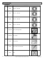
1
OWNERS MANU
AL
MK-370 EXP TILE SAW
TILE SAW
OWNER’S MANUAL &
OPERATING INSTRUCTIONS
! CAUTION
READ SAFETY
AND GENERAL
INSTRUCTIONS
CAREFULLY
BEFORE USING
SAW FOR THE
FIRST TIME
serial number
You should record the serial number
of your saw on this owner’s manual
and on the warrranty card, which must
be sent in, to be effective. be sure
to include all pertinent information
required.
Part No. 160084
Revision 12/03
SAFETY INSTRUCTIONS FOR THE MK-370 EXP TILE SAW
Congratulations on your purchase of a MK-370 EXP Tile Saw. We are certain that you will be pleased with your
purchase. MK Diamond takes pride in producing the finest construction power tools and diamond blades in the
industry.
Operated correctly, your MK-370 EXP should provide you with years of service. In order to help you, we have
included this manual. This owners manual contains information necessary to operate and maintain your MK-370
EXP safely and correctly. Please take a few minutes to familiarize yourself with the MK-370 EXP by reading
and reviewing this manual.
If you should have questions concerning your MK-370 EXP, please feel free to call our friendly customer service
department at: 800 421-5830
Regards,
MK Diamond
2
Revision 12/03, Effective Date December 30, 2003
MK-370 EXP
TABLE OF CONTENTS
SAFETY
DAMAGE PREVENTION AND INFORMATION MESSAGES: ______________ 4
SAFETY MESSAGES _____________________________________________ 4
GENERAL SAFETY PRECAUTIONS AND HAZARD SYMBOLS ____________ 4
CALIFORNIA PROPOSITION 65 MESSAGE ___________________________ 6
ELECTRICAL REQUIREMENTS AND GROUNDING INSTRUCTIONS _______ 8
TILE SAW SPECIFIC WARNINGS: _________________________________ 10
SAFETY LABEL LOCATIONS ______________________________________ 10
PRODUCT SPECIFICATIONS _____________________________________ 11
UNPACKING, TRANSPORT, STAND and ASSEMBLY
UNPACKING ___________________________________________________ 12
CONTENTS ____________________________________________________ 12
TRANSPORT ___________________________________________________ 12
TILE SAW STAND_______________________________________________ 13
ASSEMBLY ____________________________________________________ 14
SETUP, ADJUSTMENT & OPERATION
SETUP ________________________________________________________ 17
ADJUSTMENT & OPERATION _____________________________________ 20
CLEANUP _____________________________________________________ 25
MAINTENANCE AND TROUBLESHOOTING
MAINTENANCE _________________________________________________ 27
ALIGNMENT ___________________________________________________ 32
TROUBLESHOOTING ____________________________________________ 37
EXPLODED VIEW AND PARTS LIST
EXPLODED VIEW _______________________________________________ 40
PARTS LIST ___________________________________________________ 41
THEORY
THEORY OF DIAMOND BLADES___________________________________ 43
ACCESSORIES
ACCESSORIES _________________________________________________ 44
ORDERING & RETURN INSTRUCTIONS
ORDERING INFORMATION _______________________________________ 45
RETURN MATERIALS POLICY ____________________________________ 45
PACKAGING INSTRUCTIONS _____________________________________ 45
AUTHORIZED SERVICE CENTERS ________________________________ 45
MK-370 EXP
Revision 12/03, Effective Date December 30, 2003
3
SAFETY
Read and follow all safety, operating and maintenance instructions. Failure to read and follow these instructions
could result in injury or death to you or others. Failure to read and follow these instructions could also result in
damage and/or reduced equipment life.
SAFETY MESSAGES:
Safety messages inform the user about potential hazards that could lead to injury, death and/or equipment
damage. Each
on safety message will be preceded by one of the following (3) three words that identify the severity
of the message.
!
DANGER Not following instructions WILL lead to DEATH or SERIOUS INJURY
! WARNING
!
on
CAUTION
Not following instructions COULD lead to DEATH or SERIOUS INJURY
Not following instructions CAN lead to injury.
DAMAGE PREVENTION AND INFORMATION MESSAGES:
A Damage Prevention Message is to inform the user of important information and/or instructions that could lead
to equipment or other property damage if not followed. Information Messages convey information that pertains
on
to theonequipment being used. Each message will be preceded by the word NOTE, as in the example below.
NOTE: Equipment and/or property damage may result if these instructions are not followed.
on
GENERAL SAFETY PRECAUTIONS
) AND HAZARD SYMBOLS:
)
on
Safety Precautions:
((
In order to prevent injury, the following safety precautions and symbols should be followed at all times!
on
READ OWNERS MANUAL BEFORE USE
((
((
)) this equipment,
Before using
)) ensure that the person operating this machine has read and understands
all ofonthe instructions in the manual. Precaution is the best insurance against accidents. Read and
understand all safety precautions, messages, warnings and hazard symbols. You are responsible for your
own safety.
KEEP GUARDS IN PLACE
))
((
Adhere to safety guidelines: ANSI American National Standards Institute, OHSA, or local Regulations.
Never operate the saw with out the guards in place!
)
REMOVE ADJUSTING KEYS AND))WRENCHES
)
((
((
Form a habit of checking to see that keys and adjusting wrenches are removed from the power tool
before it is turned on.
))
KEEP WORK AREA CLEAN
((
Cluttered work areas and benches invite accidents.
DO NOT USE IN DANGEROUS PLACES
))
((
Do not use power tools in damp or wet locations nor expose them to rain. Always keep the work area
well lighted.
KEEP CHILDREN AWAY
All visitors and children should be kept a safe distance from work area.
4
Revision 12/03, Effective Date December 30, 2003
MK-370 EXP
))
SAFETY
((
on
((
))
MAKE THE WORKSHOP KID PROOF
on
Make the workshops kid proof by using padlocks, master switches or by removing starter keys.
((
))
DO NOT FORCE THE TOOL
A power tool will do a job better and safer operating at the rate for which it was designed.
on
))
USE THE RIGHT TOOL
((
Do not force a tool or an attachment, to do a job that it was not designed to do.
on PROPER EXTENSION CORD
USE THE
((
on
If using an extension cord make sure it is in good condition first. When using an extension cord, be sure
to use one heavy enough to
)) carry the current your product will draw. An undersized cord will cause
on in line voltage that will result in a loss of power and overheating. TABLE 1, Page 9 shows the
a drop
correct
on AWG size to use depending on cord length and nameplate ampere rating. If in doubt, use the
next heavier gage. The smaller the gage number, the heavier the cord.
USE PROPER APPAREL
))
((
on wear loose clothing, gloves, neckties, rings, bracelets, or other jewelry that may be caught in
Do not
on
moving parts. Non-slip footwear is recommended. Wear protective hair covering to contain long hair.
ALWAYS USE SAFETY GLASSES
))
((
Safety glasses should always be worn when working around power tools. In addition, a face,
dust mask or respirator should be worn if a cutting operation is dusty. Everyday eyeglasses
only have impact resistant lenses and may not prevent eye injury-they are NOT safety glasses.
))
))
((
SECURE WORK
((
Clamps or a vise should be used to hold work whenever practical. Keeping your hands free to operate
a power tool is safer.
))
((
DO NOT OVERREACH
))
((
Keep proper footing and balance at all times by not overreaching.
MAINTAIN TOOLS WITH CARE
))
((
Keep tools clean for the best and safest performance. Always follow maintenance instructions for
lubricating, and when changing accessories.
DISCONNECT TOOLS
))
((
Power tools should always be disconnected before servicing or when changing accessories, such as
blades, bits, cutters, and the like.
REDUCE THE RISK OF UNINTENTIONAL
START
on
MK-370 EXP
Make sure the ON/OFF switch is in the OFF position before plugging in a power tool.
Revision 12/03, Effective Date December 30, 2003
5
on
))
((
SAFETY
on
USE RECOMMENDED ACCESSORIES
))
((
Consult the owner’s manual for recommended accessories. Using improper accessories may increase
the risk of personal or by-stander injury.
((
))
NEVER STAND ON THE TOOL
Serious injury could occur if a power tool is tipped, or if a cutting tool is unintentionally contacted.
CHECK FOR DAMAGED PARTS
((
Before using a power tool, check for damaged parts. A guard or any other part that is damaged should
be carefully checked to determine
it would operate properly and perform its intended function. Always
))
check moving parts for proper alignment or binding. Check for broken parts and mountings and all other
conditions that may affect the operation of the power tool. A guard, or any damaged part, should be
properly repaired or replaced.
DIRECTION OF FEED
))
((
Always feed work into a blade or cutter against the direction of rotation. A blade or cutter should always
be installed such that rotation is in the direction of the arrow imprinted on the side of the blade or cutter.
NEVER LEAVE A TOOL UNATTENDED
TURN POWER OFF - Do not leave a tool until it comes to a complete stop. Always turn a power tool
OFF when leaving the work area, or, when a cut is finished.
CALIFORNIA PROPOSITION 65 MESSAGE:
! WARNING Some dust created by power sanding, sawing, grinding, drilling, and other construction
activities contain chemicals known [to the State of California] to cause cancer, birth defects or
other reproductive harm. Some examples of these chemicals are:
• Lead, from lead-based paints
• Crystalline silica, from bricks and cement and other masonry products and
• Arsenic and chromium, from chemically treated lumber
For further information, consult the following sources:
http://www.osha-slc.gov/sltc/silicarystalline/index.html
http://www.oehha.org/prop65/out_of_date/6022kLstA.html
Your risk from these exposures varies depending on how often you do this type of work. To reduce your
exposure to these chemicals, work in a well-ventilated area, and work with approved safety equipment, such as
those dust masks that are specially designed to filter out microscopic particles.
6
Revision 12/03, Effective Date December 30, 2003
MK-370 EXP
))
((
SAFETY
Hazard Symbols:
Electrical Shock!
))
Never touch electrical wires or components while the engine is running. They can be sources of
electrical shock which could cause severe injury or burns.
((
on
Rotating Parts!
((
)) clothing away from all moving parts to prevent injury. Never operate the
Keep hands, feet, hair, and
engine with covers, shrouds, or guards removed.
Over Speed!
((
))
Never tamper with the governor components or settings to increase the maximum speed. Severe
personal injury and damage to the engine or equipment can result if operated at speeds above
maximum.
! WARNING Sawing and drilling generates dust. Excessive airborne particles may cause irritation to eyes,
skin and respiratory tract. To avoid breathing impairment, always employ dust controls and
protection suitable to the material being sawed or drilled; See OSHA (29 CFR Part 1910.1200). Diamond
Blades improperly used are dangerous. Comply with American National Standards Institute Safety Code, B7.1
and, Occupational Safety and Health Act covering Speed, Safety Guards, Flanges, Mounting Procedures,
General Operating Rules, Handling, Storage and General Machine Conditions
MK-370 EXP
Revision 12/03, Effective Date December 30, 2003
7
SAFETY
ELECTRICAL REQUIREMENTS AND GROUNDING INSTRUCTIONS:
In order to prevent potential electrical shock and injury, the following electrical safety precautions and symbols
should be followed at all times!
! WARNING
In case of a malfunction or breakdown, grounding provides a path of least resistance for electric current
to reduce the risk of electric shock. This tool is equipped with an electric cord having an equipmentgrounding conductor and a grounding plug. The plug must be plugged into a matching outlet that is
properly installed and grounded in accordance with all local codes and ordinances.
• Do not modify the plug provided – if it will not fit the outlet; have the proper outlet installed by a
qualified electrician
• Improper connections of the equipment-grounding conductor can result in a risk of electric shock.
The equipment-grounding conductor is the insulated conductor that has an outer surface that
is green, with or without yellow stripes. If repair or replacement of the electric cord or plug is
necessary, do not connect the equipment-grounding conductor to a live terminal
• Check with a qualified electrician or service personnel if the grounding instructions are not
completely understood, or if in doubt as to whether the tool is properly grounded
• Use only 3-wire extension cords that have 3-prong grounding plugs and 3-pole receptacles that
accept the tool’s plug
• Repair or replace a damaged or worn cord immediately
! WARNING
This tool is intended for use on a circuit that has an outlet that looks like the one shown in Sketch A of
Figure 1. The tool has a grounding plug that looks like the plug illustrated in Sketch A of FIGURE 1. A
temporary adapter, which looks like the adapter illustrated in sketches B and C, may be used to connect
this plug to a 2-pole receptacle as shown in Sketch B, if a
properly grounded outlet is not available. The temporary adapter
should be used only until a properly grounded outlet can be
installed by a qualified electrician. The green-colored rigid ear,
lug, and the like, extending from the adapter, must be connected
to a permanent ground such as a properly grounded outlet box.
NOTE: Use of a temporary adapter is not permitted in Canada
FIGURE 1
! WARNING
To reduce the risk of electrocution, keep all connections dry and off the ground.
A Ground Fault Circuit Interrupter (GFCI) should be provided on the circuit(s) or outlet(s) to be used for
the Saw. Receptacles are available having built-in GFCI protections and may be used for this measure
of safety.
When using an extension cord, the GFCI should be installed closest to the power source, followed by the
extension cord and lastly, the saw.
8
Revision 12/03, Effective Date December 30, 2003
MK-370 EXP
SAFETY
To avoid the possibility of the appliance plug or receptacle getting wet, position the saw to one side of a
wall mounted receptacle. This will prevent water from dripping onto the receptacle or plug. A “drip loop,”
shown in FIGURE 2, should be arranged by the user to properly position the power cord relative to the
power source.
The “drip loop” is that part of the cord below the level of the receptacle, or the
connector, if an extension cord is used. This method of positioning the cord prevents
the travel of water along the power cord and coming in contact with the receptacle.
If the plug or receptacle gets wet, DO NOT unplug the cord. Disconnect the fuse or
circuit breaker that supplies power to the tool. Then unplug and examine for presence
of water in the receptacle.
Drip Loop
FIGURE 2
! WARNING
Use only extensions cords that are intended for outdoor use. These extension cords are identified
by a marking “Acceptable for use with outdoor appliances; store indoors while not in use.” Use
only extension cords having an electrical rating not less than the rating of the product. Do not use
damaged extension cords. Examine extension cords before using and replace if damaged. Do not
abuse extension cords and do not yank on any cord to disconnect. Keep cords away from heat and
sharp edges. Always disconnect the extension cord from the receptacle before disconnection the
product form the extension cord.
! WARNING
To reduce the risk of electrocution, keep all connections dry and off the ground. Do not touch the
plug with wet hands.
! WARNING
Use of under size extension cords result in low voltage to the motor that can result in motor burnout
and premature failure. MK Diamond warns that equipment returned to us showing signs of being run
in a low voltage condition, through the use of undersized extension cords will be repaired or replaced
totally at the customers expense. There will be no warranty claim.
To choose the proper extension cord,
• Locate the length of extension cord needed in TABLE 1 below.
• Once the proper length is found, move down the column to obtain the correct AWG size required
for that length of extension cord.
Extension Cord Minimum Gage for Length
Volts
Total Length of Cord in Feet
120 V
25 ft.
50 ft.
100 ft.
150 ft.
AWG
AWG
AWG
AWG
14
12
Not Recommended
TABLE 1
MK-370 EXP
Revision 12/03, Effective Date December 30, 2003
9
SAFETY
SAFETY LABEL LOCATIONS
Safety labels are located according to Figures 1 through 4 below. The labels contain important safety
information. Please read the information contained on each safety label. These labels are considered a
permanent part of your saw. If a label comes off or becomes hard to read, contact MK Diamond or your dealer
for a replacement
Item
1A
1B
2
3A
3B
4A
4B
Location
Motor – Right Side
Motor – Right Side
Motor – Left Side
Cutting Head – Top
Cutting Head – Top
Pump – Left Side
Pump – Right Side
Description
Caution – Receptacle is for Water Pump Only
Motor Specifications
Caution – Use with Ground Fault Circuit Interrupter
MK-370 EXP Serial Number
Warning – Read Owners Manual
Warning – Connect to Grounded Receptacle
Pump Specifications
A
Part No.
154822
N/A
155678
157249-4
155806
N/A
N/A
B
2
1
B
A
B
A
4
3
TILE SAW SPECIFIC WARNINGS:
! WARNING Wear eye protection.
Use splash hood for every operation for which it can be used.
Disconnect saw before servicing, when changing cutting blades, and cleaning.
Replace damaged cutting blade before operating.
10
Revision 12/03, Effective Date December 30, 2003
MK-370 EXP
SAFETY
PRODUCT SPECIFICATIONS
The MK-370 EXP is a versatile Tile Saw. Operated and used according to this manual, the MK-370 EXP will
provide years of dependable service.
General Description
The MK-370 EXP Tile Saw is engineered as a tabletop or stand mounted wet tile saw. The saw includes a
powerful 115V electric motor. The saw is capable of cutting tile up to twelve (12) inches in length. The saw can
cut an object one and three quarters (1-3/4) inches thick in one pass.
Motor Specifications
Motor specifications for the MK-370 EXP are listed in Table 2 below.
Voltage
Overall Amperage
Frequency
RPM
Horse Power
115V
5.3 A
50/60Hz
5500 rpm
1/2 hp
Table 2
Blade Capacity:
The MK-370 EXP uses a 7 (7) inch (178mm) diameter, wet cutting continuous rim, MK Diamond blade with a
five-eighths (5/8) inch (15.875 mm) arbor.
Tile Types:
The MK-370 EXP can cut a variety of tile types including Porcelain, Terra-cotta, Marble, Quarry and Slate,
Ceramic or almost any other non-ferrous material.
NOTE: The MK-370 EXP is not designed to cut plastic or ferrous (metals) material.
MK-370 EXP
Revision 12/03, Effective Date December 30, 2003
11
UNPACKING, TRANSPORT, STAND and ASSEMBLY
UNPACKING
The MK-370 EXP is not designed to cut plastic or ferrous (metals) material.
!
CAUTION
Use proper lifting techniques when lifting the MK-370 EXP
If not done, remove the MK-370 EXP, accessory box from the carton.
CONTENTS
In your container, you will find
One (1) MK-370 cutting surface and water pan,
One (1) MK-370 cutting head,
One (1) 7-inch wet cutting continuous rim blade,
One (1) splash guard,
One (1) splash guard washer,
One
One
One
One
One
(1)
(1)
(1)
(1)
(1)
splash guard wing nut,
electric water pump,
pump discharge fitting,
cooling transfer tube
Flow adjusting Clamp
One
One
One
One
One
(1)
(1)
(1)
(1)
(1)
blade wrench
shaft wrench,
owners manual,
pump manual and
warranty card.
MK-370 EXP
Cutting Surface
MK-370 EXP
Cutting Head
Diamond Blade
Splash Guard
Splash Guard
Washer
Splash Guard
Wing Nut
Electric
Water Pump
Pump
Discharge Fitting
Cooling
Transfer Tube
Flow
Adjusting Clamp
Blade Nut
Wrench
Inner Flange
Wrench
Owners
Manual
Pump
Manual
Warranty
Card
TRANSPORT:
!
CAUTION 1. The MK-370 EXP weighs approximately forty-six (46) pounds; use care when transporting.
2. Never transport the MK-370 EXP with water in the Water Pan.
The MK-370 EXP is designed with a rigid frame and removable Cutting Head making the saw easily
transportable. To lift the saw, grasp the front and back of the frame at the lift points shown below.
Cutting
Head
Lift Point
Lift Point
12
Revision 12/03, Effective Date December 30, 2003
MK-370 EXP
UNPACKING, TRANSPORT, UNIVERSAL STAND and ASSEMBLY
TILE SAW STAND
!
CAUTION 1. The MK-370 EXP weighs approximately thirty (30) pounds; use care when transporting.
2. Never transport the MK-370 EXP with water in the Water Pan.
(A)
Open the Stand
and place on flat surface
(B)
Orient the Saw to the Stand
(D)
Sit the Water Pan on top of
the Stand Supports
MK-370 EXP
(C)
Align the Stand supports to
the depressions on the pan
(E)
Verify that the saw is stable in
place
Revision 12/03, Effective Date December 30, 2003
13
UNPACKING, TRANSPORT, UNIVERSAL STAND and ASSEMBLY
ASSEMBLY:
Follow the assembly instructions to prepare your MK-370 EXP for operation.
1. Cutting Head Installation:
NOTE: If the Cutting Head is installed, go to step 2.
Flat Washer
(A)
Place the Flat Washer onto
the Height Adjusting Knob
(B)
Align Cutting Head Pivot Hole
to the Post, Pivot Shaft
(C)
Verify the Cutting Head is
completely installed and
seated on the Post
(D)
Install the Height Adjusting
Knob through the Post into
the Cutting Head and tighten
the Knob
2. Diamond Blade Installation:
NOTE: When installing the Retaining Screw, do not "cross-thread" and DO OT over tighten the screw.
(A)
Loosen and remove the Blade
Guard, Retaining Knob
14
(B)
Loosen the Blade Guard,
Retaining Wing nut
Revision 12/03, Effective Date December 30, 2003
(C)
Open the Blade Guard
MK-370 EXP
UNPACKING, TRANSPORT, UNIVERSAL STAND and ASSEMBLY
Motor Shaft
Motor
Inner blade
Guard
Turn CounterClockWise
Blade Wrench
Shaft Wrench
(D)
Place the Shaft Wrench
between the Inner Blade
Guard and the Motor and onto
the Motor Shaft
(E)
Using the Blade and Shaft
Wrenches, loosen and remove
the Retaining Nut and Outer
Flange
(F)
Install Diamond Blade
onto Blade Shaft
Rotate CCW to
close
(G)
Install the Retaining Nut and
Outer Flange and then tighten
using the Blade and Shaft
Wrenches
(H)
Close the Blade Guard
(J)
Tighten the Blade Guard
Retaining, Wing nut
MK-370 EXP
(I)
Verify the Blade is seated on
the Blade Shaft and direction
of rotation is correct
(K)
Tighten the Blade Guard,
Retaining Knob
Revision 12/03, Effective Date December 30, 2003
15
UNPACKING, TRANSPORT, UNIVERSAL STAND and ASSEMBLY
3. Adjustable Cutting Guide Installation:
NOTE: The Adjustable Cutting Guide can be used on either side of the Diamond Blade.
(A)
Loosen Adjustable Cutting Guide
retaining thumbscrew and place it over
the Movable Cutting Table, Ruler/Stop
(B)
Place the Adjustable Cutting Guide onto
the Movable Cutting, Table Ruler/Stop
and tighten the retaining thumbscrew
4. Splash Guard Installation
(A)
Install the retaining thumbscrew
through the washer and Splash
Guard then align to the hole found on
back of the Blade Guard
(B)
Install the Splash Guard
onto the Blade Guard
5. Water Pump Preparation:
(A)
Install Water Pump
Discharge Fitting
16
(B)
Press one end of the Cooling
Transfer Tube onto the Water
Pump Discharge Fitting
Revision 12/03, Effective Date December 30, 2003
(C)
Slide Cooling Flow Adjusting
Clamp onto the Cooling
Transfer Tube
MK-370 EXP
SETUP, ADJUSTMENT & OPERATION
SETUP:
1. Pre-start Inspection:
Prior to beginning work, a pre-start inspection of the saw should be performed.
(A)
Ensure the ON/OFF Switch
is in the OFF position
(B)
Verify the Movable Cutting
Table moves freely
(D)
Inspect the Pump Assembly
for damage – ensure the cord
is free of cracks or cuts
(C)
Inspect the Diamond Blade for
damage – verify the blade is
correct for the type of material
being cut
(E)
Inspect the MK-370 EXP for
damage – ensure the cord is
free of cracks or cuts
2. Connecting the Water Pump:
! WARNING 1. To prevent the possibility of electrical shock, the MK-370 EXP MUST be de-energized when
connecting the Water Pump.
2. To prevent the possibility of electrical shock, use only MK Diamond qualified replacement
parts.
NOTE: To prevent pump damage, the Water Pump must be disconnected if cutting with a Dry Blade.
(A)
Connect the Cooling Transfer
Tube to the inlet connection of
the Blade Guard
MK-370 EXP
(B)
Connect the Water Pump power
cord to the connection found on
the back of the motor
Revision 12/03, Effective Date December 30, 2003
17
SETUP, ADJUSTMENT & OPERATION
3. Water Pump Setup for Operation:
The Water Pump can be setup for operation in two ways: external Water Source or Re-circulation.
NOTE: If using a dry blade for operation, DO NOT connect the water pump.
I. Re-circulation:
NOTE: When using the re-circulation method, the water should be changed often for longer pump life
(A)
Ensure that Cooling Transfer
Tube is connected
18
(B)
Place the Water Pump in the
back of the Water Pan
Revision 12/03, Effective Date December 30, 2003
(C)
Fill the Water Pan until water
completely covers the Water
Pump suction
MK-370 EXP
SETUP, ADJUSTMENT & OPERATION
4. MK-370 EXP Setup for Operation
!
CAUTION 1. Before powering or starting, check for damage that could prevent this equipment from proper
operation or performing it’s intended function. Check for binding and alignment of moving
parts. Check for damaged, broken, or missing parts.
2. Verify the On/Off switch is in the OFF position.
3. Before connecting the MK-370 EXP to a power supply, be sure the voltage, cycle and phase
of the job site power source meet the requirements of TABLE 3
VOLTAGE
115V
CYCLE
60Hz
PHASE
1-phase
TABLE 3
4. Use an approved Ground Fault Circuit Interrupter (GFCI)
5. Do not cover the motor vents as this could lead to motor overheating.
NOTE: 1. In order to avoid breaker tripping, a 20-amp circuit breaker should be used.
2. If using an extension power cord, make sure the length and wire gauge correspond to he
requirements listed in TABLE 1 on page 9. An extension power cord that is too small in wire gauge
(diameter), or too long in length, will cause the motor to overheat and could cause premature failure.
GFCI
(A)
Ensure the ON/OFF Switch is
in the OFF position
MK-370 EXP
(B)
Plug MK-370 EXP into the
GFCI
Revision 12/03, Effective Date December 30, 2003
(C)
Plug the GFCI into the Power
source
19
SETUP, ADJUSTMENT & OPERATION
ADJUSTMENT & OPERATION
1. Cutting Straight Edges:
!
CAUTION
DO NOT FORCE THE TOOL. It will do the job better and safer at the rate for which it was
designed.
Desired cut length
indicated here
(A)
Loosen the Adjustable Cutting
Guide retaining thumbscrew
(B)
Position the Adjustable
Cutting Guide to desired cut
length
(C)
Tighten the retaining
thumbscrew
(E)
Turn the motor ON
(F)
Verify cooling flow on both
sides of the blade
Ruler/Stop
(D)
Place the tile against the
Ruler/Stop and Cutting Guide
(G)
Perform the cut
20
(H)
Turn the motor OFF when
work is complete
Revision 12/03, Effective Date December 30, 2003
MK-370 EXP
SETUP, ADJUSTMENT & OPERATION
2. Cutting 45° Miters:
The MK-370 EXP is designed with an adjustable Cutting Head for precision 45º Miter Cuts.
DO NOT FORCE THE TOOL. It will do the job better and safer at the rate for which it was
! CAUTION designed.
Pivot Direction
(A)
Loosen the Cutting Head
Pivot, Retaining Knob
(B)
Pivot the Cutting Head to the
45º cutting position
(C)
Tighten the Cutting Head,
Pivot Retaining Knob
(D)
Loosen the Adjustable Cutting
Guide retaining thumbscrew
(E)
Position the Adjustable
Cutting Guide to
desired cut length
(F)
Tighten the retaining
thumbscrew
(G)
Place the tile against the
Ruler/Stop and Cutting Guide
(H)
Turn the motor ON
(I)
Verify cooling flow on both
sides of the blade
MK-370 EXP
Revision 12/03, Effective Date December 30, 2003
21
SETUP, ADJUSTMENT & OPERATION
Cutting 45° Miters (cont...)
Pivot Direction
(J)
Perform the cut
22
(K)
Turn the motor OFF when
work is complete
Revision 12/03, Effective Date December 30, 2003
(L)
Return the Cutting Head to
the upright position when
complete
MK-370 EXP
SETUP, ADJUSTMENT & OPERATION
3. Diagonal Cutting:
NOTE: To cut diagonal, the Dual 45º Flat Angle Guide (MK Diamond Part No. 134557-MK) should be used.
!
CAUTION
DO NOT FORCE THE TOOL. It will do the job better and safer at the rate for which it was
designed.
(A)
Remove the Adjustable
Cutting Guide
(B)
Place the Dual 45º Flat Angle
Guide on the Ruler/Stop
(C)
Position the Dual 45º Flat
Angle Guide and tighten the
retaining knob
NOTE: If Cutting the tile in two equal halves, align the tile in the
V-notch of the Movable Cutting Table Ruler/Stop.
Ruler/Stop
(D)
Position the tile against the
Dual 45º Flat Angle Guide and
the Ruler/Stop
(E)
Turn the motor ON
(G)
Perform the cut
MK-370 EXP
(F)
Verify cooling flow on both
sides of the blade
(H)
Turn the motor OFF when
work is complete
Revision 12/03, Effective Date December 30, 2003
23
SETUP, ADJUSTMENT & OPERATION
4. Off-angle Cutting:
NOTE: Use a Protractor (MK Part No. 134569-MK) to cut angles other than 45º angles. (not included)
! CAUTION DO NOT FORCE THE TOOL. It will do the job better and safer at the rate for which it was designed.
Adjustable
cutting guide
Turn CCW to
loosen
Ruler/Stop
(A)
Remove the Adjustable
Cutting Guide
(B)
Place the Protractor on the
Ruler/Stop
(C)
Set the desired angle on the
Protractor Gage
Desired cut length
indicated here
(D)
Tighten the Protractor Gage
retaining knob
(E)
Position the Protractor Cutting
Guide to the desired length
(F)
Tighten the retaining knob
(G)
Position the tile against the
Protractor and the Ruler/Stop
(H)
Turn the motor ON
(I)
Verify cooling flow on both
sides of the blade
(G)
Perform the cut
24
(H)
Turn the motor OFF when
work is complete
Revision 12/03, Effective Date December 30, 2003
MK-370 EXP
SETUP, ADJUSTMENT & OPERATION
CLEANUP
NOTES: Dispose of wastewater in accordance with applicable Federal, State and Local laws.
Suction
Screen
(A)
Remove the pump Suction
Screen and clean the Water
Pump of all debris
!
CAUTION
(B)
Fill the Water Pan with clean
water
(C)
Run the MK-370 EXP until
clear water is seen at the
blade Cooling Flow Points
(Approx. 1 minute)retaining
thumbscrew
Ensure the saw is disconnected before completing the remainder of the cleanup process.
GFCI
(D)
Ensure the ON/OFF Switch is
in the OFF position
(E)
Unplug the GFCI from the
Power source
(F)
Unplug MK-370 EXP from the
GFCI
(G)
Remove the Cutting Assembly
from the Water Pan
(H)
Dispose the contents of the
Water Pan
(I)
Clean the MK-370 with soap
and clean water
MK-370 EXP
Revision 12/03, Effective Date December 30, 2003
25
SETUP, ADJUSTMENT & OPERATION
(I)
Clean the Water Pan
!
CAUTION
(J)
Clean the Adjustable Cutting
Guide, Guide Bar
(K)
Clean the Roller Wheel Guide
Rail
Ensure water is not forced into the motor casing when cleaning.
(L)
Clean the remainder of the
MK-370 EXP
26
Revision 12/03, Effective Date December 30, 2003
MK-370 EXP
MAINTENANCE AND TROUBLESHOOTING
MAINTENANCE
1. Maintenance Following Use:
To extend the life of the MK-370 EXP, the following procedure should be performed after each use. Lubricate
all points listed below with light oils such as, 3 in 1, WD-40, etc.
(A)
Ensure the ON/OFF Switch is
in the OFF position
(B)
Unplug MK-370 EXP
(C)
Lubricate the Guide Bar
Roller Wheel
Assembly
(D)
Lubricate the Roller Wheel
Assembly
2. Monthly Maintenance:
The following maintenance should be performed Monthly.
Turn CCW
Inner Flange
Outer Flange
Retaining Nut
(A)
Remove the Diamond Blade,
Outer Flange and Retaining
Nut
MK-370 EXP
(B)
Remove the Inner Flange
Revision 12/03, Effective Date December 30, 2003
Inner Flange
(C)
Clean and Lubricate the Inner
and Outer Flanges and the
Retaining Nut
27
MAINTENANCE AND TROUBLESHOOTING
Blade Guard
Pivot Shaft
(D)
Clean around Motor Shaft
Front Pivot
Point
(E)
Remove the Blade Guard then
clean and Lubricate the Blade
Guard Pivot Shaft
(F)
Lubricate the front Cutting
Head Pivot Point
(H)
Remove the Cutting Head
(I)
Clean the Cutting Head Pivot
Holes
Rear Pivot
Point
(G)
Lubricate the rear Cutting
Head Pivot Point
Pivot Shaft
(J)
Lubricate the Cutting Head
Pivot Holes
(K)
Lubricate the Cutting Head
Pivot Shaft
(M)
Verify the Cutting Table Roller
Wheel Assembly is tight
28
(L)
Lubricate the Cutting Head
Adjustment Knob
(N)
Verify that the Roller Wheel is
tight
Revision 12/03, Effective Date December 30, 2003
MK-370 EXP
MAINTENANCE AND TROUBLESHOOTING
3. Flow Adjustment:
NOTE: If flow to the diamond blade requires adjustment, perform the following actions.
(A)
Increase cooling flow by
releasing the Flow Adjusting
Clamp
MK-370 EXP
(B)
Reduce cooling flow by
Pressing down on the Flow
Adjusting Clamp
Revision 12/03, Effective Date December 30, 2003
29
MAINTENANCE AND TROUBLESHOOTING
4. Blade Dressing
Like most cutting instruments, a diamond blade performs best when it is dressed. Over time and use, diamonds
on the outer edge of the blade will become smoothed or “glazed” over.
This will reduce grinding efficiency and may cause the blade to “wander” or bend giving the illusion of an
alignment problem. When this occurs, the blade will need to be dressed.
The diamond blade can be dressed using the MK Dressing Stick (part number 152792) and by following the
steps below.
Adjustable
cutting guide
(A)
Setup the MK-370 EXP
for operation (See Setup,
Adjustment and Operation)
(B)
Set the Adjustable Cutting
Guide to cut a 1/16-strip
(C)
Position the Dressing Stick
(D)
Turn the motor ON
(E)
Verify cooling flow on both
sides of the blade
(F)
Cut the Dressing Stick 7 or 8
times to dress the Blade
(G)
Ensure the ON/OFF Switch is
in the OFF position
30
Revision 12/03, Effective Date December 30, 2003
MK-370 EXP
MAINTENANCE AND TROUBLESHOOTING
5. Diamond Blade Change-out:
NOTE: When installing the Retaining Nut, do not “cross-thread” and DO NOT over tighten the screw.
Rotate CW to
Open
(A)
Open the Outer Blade
Turn CCW
(B)
Remove Retaining Nut and
Outer Flange
(C)
Remove Diamond Blade from
Blade Shaft
Turn CW
(D)
Install the Diamond Blade
onto Blade Shaft
(E)
Install the Retaining Nut and
Outer Flange and then tighten
using the Blade and Shaft
Wrenches
(F)
Verify the Blade is seated on
the Blade Shaft and direction
of rotation is correct
Rotate CCW to
Close
(G)
Close the Outer Blade
MK-370 EXP
Revision 12/03, Effective Date December 30, 2003
31
MAINTENANCE AND TROUBLESHOOTING
ALIGNMENT:
The Movable Cutting Table of the MK-770 is pre-aligned in the factory. It may become misaligned with the
Cutting Head of the Tile Saw over time. Should misalignment occur, perform the following steps to realign it.
NOTE: If alignment problems are the result of a warped blade, a bent frame or bent support arm, or, if
alignment is off by more than 1/8-inch, contact the MK Diamond Service Center – (800) 474-5594
TOOLS NEEDED:
Combination Square
12-inch or Greater
1/2-inch Wrench
1/4-inch Wrench
Flat Head Screwdriver
(B)
Inspect Tile Saw
for damage
(C)
Inspect Diamond Blade
for damage
PREPARATION:
(A)
Remove Tile Saw
from Power Source
32
Revision 12/03, Effective Date December 30, 2003
MK-370 EXP
MAINTENANCE AND TROUBLESHOOTING
MOVABLE CUTTING TABLE ALIGNMENT VERIFICATION:
This will verify the Movable Cutting Table is aligned to the frame of the saw.
NOTES:
If the blade is misaligned following alignment verification, attempt to align using Alignment Screw, 90º
Verification. The Diamond Blade must be removed and reinstalled when removing the Blade Guard.
Lock
Blade Guard retaining
wing nut
Flat Surface
(A)
Remove Blade Guard
(B)
Place Square on guide bar
side of cutting table
(C)
Lock in position
(D)
Move Square to wheel
assembly side of the cutting
table
(E)
Verify Wheel Assembly side of
Movable Cutting Table height
is same as Guide Bar side
(F)
If Gap exists, loosen Movable
Cutting Table Wheel
Assembly
Square
No Gap
(G)
Move Wheel Assembly up or
down to Square the Movable
Cutting Table
MK-370 EXP
(H)
Check that there is no gap
between the Square and the
wheel assembly side of frame
Revision 12/03, Effective Date December 30, 2003
(I)
Tighten Movable Cutting
Table Wheel Assembly
33
MAINTENANCE AND TROUBLESHOOTING
Alignment Screw, 90° Verification:
90º-alignment verification will ensure that the blade will cut the tile straight up and down and not at an angle.
NOTES:
If the blade is misaligned following this alignment procedure, return the saw to MK Diamond for
repair. The Diamond Blade must be removed and reinstalled when removing the Blade Guard.
Rotate Knob Counterclockwise to loosen
Lower
Screw
(A)
Position the Cutting Head
to the 45° Cutting Angle
(B)
Locate the 90°
Adjustment Screw
(C)
Rotate 90° Adjustment Screw
clockwise or counter-clockwise
to realign Cutting Head
No gaps between
Blade and Square
(D)
Position the Square on
Movable Cutting Table
against the Diamond Blade
34
(E)
Verify the Diamond Blade
is Square to the Movable
Cutting Table
Revision 12/03, Effective Date December 30, 2003
(F)
Repeat Steps A to E as
necessary to align the
Cutting Head
MK-370 EXP
MAINTENANCE AND TROUBLESHOOTING
Horizontal Rough Alignment:
The Horizontal alignment will ensure that straight cuts (or Rip Cuts) are made.
1/4-inch Wrench
Rotate Clockwise or
Counterclockwise to
Adjust Height
(A)
Position Cutting Head
to normal Cut Depth
(B)
Loosen front and rear
Guide Bar Retaining Bolts
Horizontal Final Alignment:
(C)
Move Guide Rail and Table
until the Blade is centered in
Cutting Groove
Ruler/Stop
(A)
Pull Movable Cutting Table
to front of Tile Saw
(B)
Position Square flat on Movable
Cutting Table against Ruler/Stop
(C)
Position front of Square
against Blade
(D)
Move Guide Bar and table until
Square rests evenly across Blade
(E)
Position end of Square
against Blade
(F)
Move Guide Bar and table until
Square rests evenly across Blade
Horizontal Alignment Verification:
(A)
Move the Cutting Table back and
forth to verify Blade is even
across all points of Square
MK-370 EXP
(B)
Tighten Guide Bar
Retaining Bolts
Revision 12/03, Effective Date December 30, 2003
(C)
Move the Cutting Table back and
forth to re-verify Blade is even
across all points of Square
35
MAINTENANCE AND TROUBLESHOOTING
45° Alignment Verification:
The 45° Alignment Verification is done to ensure the blade will cut tile at a 45° angle.
NOTES:
If the blade is misaligned following this alignment procedure, return the saw to MK Diamond for
repair. The Diamond Blade must be removed and reinstalled when removing the Blade Guard.
Rotate Knob Counterclockwise to loosen
Square
Blade Guard retaining
wing nut
(A)
Remove Blade Guard
(If not done Previously)
(B)
Position the Cutting Head
to the 45° Cutting Angle
Upper
Screw
No Gaps between
Blad eand Square
(D)
Verify Blade is even
across all points of Square
(C)
Place Square on the Movable
Cutting Table and position the
Square against the Blade
(E)
To Adjust 45° Cutting Angle,
locate the 45°
Adjustment Screw
(F)
Rotate 45° Adjustment Screw
clockwise or counter-clockwise
to realign 45° Cutting Angle
No Gaps between
Blad eand Square
(G)
Verify Blade is now even
across all points of Square
36
(H)
Repeat steps A to G until Blade
is even across all points of
Square
Revision 12/03, Effective Date December 30, 2003
MK-370 EXP
MAINTENANCE AND TROUBLESHOOTING
TROUBLESHOOTING
1. Blade will not cut properly:
If "Glazed" then
Dress Blade
If Blade Core is bent, or Arbor is out
of round, change blade
(A)
Check for Smoothness or
“Glazing” (Dress blade if
needed)
(B)
Check for proper rotation
(D)
Verify the blade is correct for
the material being used
(C)
Ensure the Blade Core is not
bent and Arbor is not out of
round
(E)
Return to MK Diamond
for Repair
2. Movable Cutting Table Does Not Move Correctly:
(A)
Check that the Guide Bar is
clean – clean if dirty
MK-370 EXP
(B)
Check the Movable Cutting
Table Roller Wheel for wear
replace if necessary
Revision 12/03, Effective Date December 30, 2003
(C)
Return to MK Diamond
for Repair
37
MAINTENANCE AND TROUBLESHOOTING
3. Cooling Flow:
(A)
Check cooling flow Adjusting
Clamp open
(B)
Remove the Cooling Transfer
Tube from the Blade Guard
inlet
(C)
Place Pump into a bucket of
water and check flow
Intake Screen
(D)
Remove the Cooling Transfer
Tube and check flow
((E)
Remove the Pump Discharge
Fitting and check
(I)
Remove the Blade Guard
Intake Fitting
38
(F)
Remove the Pump Intake
Screen and check for debris
(J)
Clean the Blade Guard Intake
Fitting
Revision 12/03, Effective Date December 30, 2003
MK-370 EXP
MAINTENANCE AND TROUBLESHOOTING
NOTE: “Rodding” cooling channels is performed by inserting a small wire rod through the cooling inlet on top
of the Blade Guard and directing the rod out through each of the cooling flow tubes located on the
the Blade Guard. The cooling channels should be “rodded” until all ports are free of
underside of
foreign debris.
(K)
Rod Cooling Channels and
recheck flow
(L)
Return to MK Diamond
for Repair
4. Blade Stops Turning
GFCI
(A)
Verify all plugs are fully
installed
(D)
Verify circuit breaker not
tripped If tripped, reset once
MK-370 EXP
(B)
Check to see if the Ground
Fault Circuit Interrupter (GFCI)
is tripped
(C)
Verify circuit breaker at least
20 amps – if not, move to
20-amp circuit
(E)
Check power source voltage
is 115V – if not 115v, move to
another circuit
(L)
Return to MK Diamond
for Repair
Revision 12/03, Effective Date December 30, 2003
39
EXPLODED VIEW AND PARTS LIST
MK-370 EXP
EXPLODED VIEW
40
Revision 12/03, Effective Date December 30, 2003
MK-370 EXP
MK-370 EXP PARTS LIST
PARTS LIST:
Item
A
A1
A2
A3
A4
A5
A6
Qty
1
1
1
1
1
1
1
1
1
1
1
Part #
n/a
134684
153450
153441
160084
155037
134551-MK
134551
159428-1
153366
156915
B2
B3
B4
B5
Assembly, Blade Guard, 7”
Guard, 7” Blade (comp)
Guard, 7” Blade (raw)
Elbow, 1/8 MNPT X 1/4 BARB 90° Brass
Knob, Davies
Washer, 5/16 SAE Flat
Wingnut, 5/16-18 Nylok
1
1
1
1
1
2
1
154811-MK
154811
154810
154652
151681
151754
151746
C
C1
Carton
Carton, MK-370EXP
1
1
n/a
160044
D
D1
D2
D3
D4
D5
D6
D7
D8
D9
D10
D11
D12
Assembly, Cutting Head
Cutting Head (Comp)
Cutting Head (Raw)
Helicoil, 3/8-16x3/8
Screw, Slotted Pan Head, 10-32x3/4
Screw, Slotted Pan Head, 10-32x1
Nut, Hex 10-32
Screw, Hex Head, 1/4-20x3/4
Nut, Hex, 1/4-20
Knob, Tri Plastic
Label, Warning, Read Owner’s Manual
Label, Serial Number, UL/CSA Mark
Cover, Splash
Screw, Hex Head, 1/4-20x3/8
1
1
1
1
1
1
2
1
1
1
1
1
1
1
n/a
159937
159936
153486
151750
151751
151749
152370
151893
156770-01
155806
157249-04
160279
153526
E
E1
E2
E3
Frame
Frame
Pan, Water
Screw, Shoulder, Soc Head, 1/4-20 x 1
1
1
1
1
n/a
159935
160041
160045
F
F1
F2
F3
F4
Assembly, Guide Bar, 3/4 Dia
Bar, Guide, 3/4 Dia
Steel, C1045 Chromed rod, 3/4 Dia x 2.25’
Screw, 5/16-18 X 1 Hex Head Cap
Washer, 5/16 Split Lock
Washer, 5/16 SAE Flat
1
1
1
2
2
2
159942-MK
159942
154186
151743
151747
151754
G
G1
Linear Bearing, 3/4 Dia
Bearing, Multilube
1
2
n/a
152227
A7
A8
B
B1
MK-370 EXP
Description
Accessories
Wrench, Blade Nut, 15/16 Boxed End
Wrench, Blade Shaft, 11/16 Open End
Blade, 7 x 5/8 x .060
Owner’s Manual, 370EXP
Warranty Card
Assembly, Rip Guide
A6A) Rip Guide (comp)
A6B) Knob, Rubber (1/4-20x3/4)
Carton, Accessory Pack
Sell Sheet, Tile Accessory
Revision 12/03, Effective Date December 30, 2003
41
MK-370 EXP PARTS LIST (cont...)
H
H1
H2
H3
H4
H5
H6
Assembly, 120v Motor
Motor, 120v/5.3A, Sanko
Label, Caution, GFCI, 1 X 2 1/8
Label, Caution, Receptacle, 1 X 2 1/8
Screw, 10-32 X 5/8 Flat Head Phillips Cap
Flange, Blade
Nut, 5/8-18
1
1
1
1
4
2
1
160053
156428-S
155678
154822
157554
135830
135848
J
J1
Assembly, Motor Mount
Motor Mount (Comp)
Motor Mount (Raw)
Washer, 5/16 Split Lock
Screw, 5/16-18 x 2-1/2 Hex Head Cap, Full Thread
Knob, Davies
Bolt, Shoulder, Soc Head, 1/2 x 1/2
Bolt, Shoulder, Soc Head, 5/16 x 5/8
Washer, 5/16 SAE Flat
1
1
1
1
1
1
2
1
1
160052
159941
159940
151747
151748
151681
151753
152137
151754
K2
K3
Assembly, Post Cover
Cover, Post (comp)
Cover, Post (raw)
Screw, 1⁄4-20 x 1/4 Socket Head Set
Label, 370EXP Model
1
1
1
3
1
159958-MK
159958
159956
157528
160054
L
L1
L2
L3
L4
L5
Assembly, Roller Wheel
Bracket, Roller Wheel
Wheel, Roller
Screw, 1⁄4-20 X 1 1⁄4 Hex Head Cap
Washer, 1⁄4 SAE Flat
Nut, 1⁄4-20 Hex
1
1
1
1
1
1
151756
154021
151799
157145
151915
151893
M
M1
M2
M3
M4
Table
Table (Comp)
Table (Raw)
Screw, 5/16-18 X 1 Hex Head Cap
Washer, 5/16 Split Lock
Washer, 5/16 SAE Flat
1
1
2
2
2
n/a
159939
159938
151743
151747
151754
N
N1
N2
N3
Assembly, PES-100 120v Water Pump
Pump, Water, PES-100 120v
Hose, Vinyl, 1⁄4 ID x 2’
Clamp, Flow, 1⁄4-1/2
1
1
1
1
155987-MK
155987
132951
154394
J2
J3
J4
J5
J6
J7
K
K1
42
Revision 12/03, Effective Date December 30, 2003
MK-370 EXP
THEORY
THEORY OF DIAMOND BLADES
Diamond blades do not really cut; they grind the material through friction. Diamond crystals, often visible at the
leading edge and sides of the rim/segment, remove material by scratching out particles of hard, dense materials,
or by knocking out larger particles of loosely bonded abrasive material.
This process eventually cracks or fractures the diamond particle, breaking it down into smaller pieces. As a
result, a diamond blade for cutting soft, abrasive material must have a hard metal matrix composition to resist
this erosion long enough for the exposed diamonds to be properly utilized.
Conversely, a blade for cutting a hard, non-abrasive material must have a soft bond to ensure that it will erode
and expose the diamonds embedded in the matrix. These simple principles are the foundation of “controlled
bond erosion”.
Types of Cutting
There
•
•
•
are two basic types of cutting-Dry or Wet. The choice of which type of blade to use depends on:
The requirements of the job
The machine/tool utilizing the diamond blade
The preference of the operator
In the case of DRY cutting, the overwhelming popularity and quantity of hand-held saws and the flexible nature
of MK Diamond blades to professionally handle most ceramic, masonry, stone and concrete materials, make the
DRY cutting blade a very attractive tool. When using a DRY blade, the user must be aware of distinct operating
practices to ensure optimum performance. DRY cutting blades require sufficient airflow about the blade to
prevent overheating of the steel core. This is best accomplished by shallow, intermittent cuts of the material
with periods of “free-spinning” (for several seconds) between each cut, to maximize the cooling process.
For WET cutting applications, MK has the exact blade to compliment both the material to be cut and the wet
cutting machine to be used. During cutting operations, liberal amounts of water act as a coolant to support the
cutting effectiveness and longevity of the WET blade. Additionally, using water adds to the overall safety of
cutting operations by keeping the dust signature down.
Know All You Can About the Material You Wish to Cut
MK-370 EXP
Revision 12/03, Effective Date December 30, 2003
43
ACCESSORIES
ACCESSORIES
44
ITEM
NUMBER
DESCRIPTION
1.
139295
MK-200, 7 x 5/8 Arbor
2.
139311
MK-215, 7 x 5/8 Arbor
3.
158434
MK-225, 7 x 5/8 Arbor
4.
153293
MK-315, 7 x 5/8 Arbor
5.
134577-MK
Dual 45° Flat Angle Guide
6.
134569-MK
90° Protractor
8.
152792
Dressing Stone
9.
152610
Ground Fault Circuit Interrupter
10.
160131
Stand
Revision 12/03, Effective Date December 30, 2003
MK-370 EXP
ORDERING & RETURN INSTRUCTIONS
ORDERING INFORMATION
You may order MK Diamond products through your local MK Diamond distributor or, you may order direct from
MK Diamond.
NOTE: There is a $25.00 minimum order when ordering direct from MK Diamond. All purchases must be made
using VISA or MasterCard.
When
•
•
•
•
•
ordering direct from MK Diamond, please have the following information ready before calling:
The Model Number of the saw
The Serial Number of the saw
Where the saw was purchased and when
The Part Number for the part(s) being ordered
The Part Description for the part(s) being ordered
All parts may be ordered by calling toll free to – 800 421-5830 or 310 539-5221 and asking for Customer
Service. For technical questions, call – 800 474-5594.
RETURN MATERIALS POLICY
To expedite the service relative to the return of a product purchased through MK Diamond, please observe the
following:
NOTE: When returning all items, they must have been purchased within the previous twelve (12) months.
• Have the Model Number of the saw
• Have the Serial Number of the saw
• Have the location of where the saw was purchased
• Have the date when the saw was purchased
• Contact Customer Service for approval to return the item(s)
• Obtain a Returned Goods Number (RGA) authorizing the return
• Follow the packaging instructions in the following section
• Ensure your item(s) are prepaid to the destination
For returned items, call toll free to – 800 421-5830 or 310 539-5221 and ask for Customer Service. For
technical questions, call – 800 474-5594 or 310 257-2845.
PACKAGING INSTRUCTIONS
•
•
•
•
•
Remove the Blade guard and Support Angle Assembly
Dry the saw before shipping
When packing, include the following: MK-370 EXP, Diamond Blade, Blade guard and Support Angle
Assembly and Adjustable Cutting Guide (Other Accessories are not required)
Package the unit in its original container or one of comparable size (do not ship the unit partially exposed)
Ensure all parts are secured in the packaging to prevent moving
AUTHORIZED SERVICE CENTERS
For quicker repair time, you may contact MK Diamond Customer Service, toll free, at 800 421-5830 or 310 5395221 for the Authorized Service Center closest too you or visit our web site at www.mkdiamond.com.
For technical questions, call – 800 474-5594.
MK-370 EXP
Revision 12/03, Effective Date December 30, 2003
45
CALIFORNIA
PROPOSITION 65 MESSAGE
Some dust created by power sanding, sawing,
grinding, drilling, and other construction
activities contain chemicals known (to
the State of California) to cause cancer,
birth defects or other reproductive harm.
Some examples or these
chemicals are:
• Lead from lead-base
paints
• crystalline silica,
from bricks and cement
and other masonry products
and
• arsenic and chromium, from chemically
treated lumber.
Your risk from these exposures varies depending
on how often you do this type of work. To reduce
your exposure to these chemicals, work in a wellventilated area, and work with approved safety
equipment, such as those dust masks that are
specially designed to filter out
microscopic particles.
Part No. 160084
Revision 12/03
MK-370 EXP TILE SAW
TILE SAW
OWNER’S MANUAL &
OPERATING INSTRUCTIONS
MK DIAMOND PRODUCTS, INC
1315 STORM PARKWAY
TORRANCE, CA 90509-2808
(310) 539-5158
www.mkdiamond.com