1
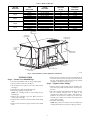
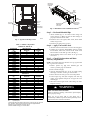
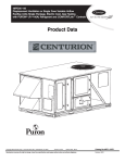
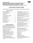
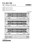
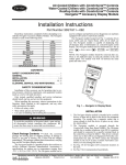
CRLPKIT1004A00 48PD05---06, 48PG03---14 Gas Heating/Electric Cooling Single Package Rooftop Units LP (Liquid Propane) Gas Conversion Kit Accessory Installation Instructions LP GAS CONVERSION KIT USAGE AND CONTENTS ACCESSORY PART NO. USAGE CRLPKIT1004A00 48PG03-14 48PD05--- 06 CONTENTS 11 Burner Orifices, Drill Size No. 50, 0.070 in. 11 Burner Orifices, Drill Size No. 51, 0.067 in. 11 Burner Orifices, Drill Size No. 52, 0.065 in. 8 Burner Orifices, Drill Size No. 53, 0.060 in. 1 LP Conversion Plate 1 LP Conversion Responsibility Label 1 Warning Label SAFETY CONSIDERATIONS Installation and servicing of air--conditioning equipment can be hazardous due to system pressure and electrical components. Only trained and qualified service personnel should install, repair, or service air--conditioning equipment. When working on equipment, observe precautions in the literature, tags and labels attached to the unit, and other safety precautions that may apply. Follow all safety codes. Wear safety glasses and work gloves. . Recognize safety information. This is the safety--alert symbol When you see this symbol on the unit and in instructions or manuals, be alert to the potential for personal injury. Understand the signal words DANGER, WARNING, and CAUTION. These words are used with the safety--alert symbol. DANGER identifies the most serious hazards which will result in severe personal injury or death. WARNING signifies a hazard which could result in personal injury or death. CAUTION is used to identify unsafe practices which may result in minor personal injury or product and property damage. NOTE is used to highlight suggestions which will result in enhanced installation, reliability, or operation. ! ELECTRICAL HAZARD WARNING SHOCK, FIRE AND EXPLOSION ! ELECTRICAL HAZARD WARNING SHOCK, FIRE AND EXPLOSION Failure to follow this warning could result in personal injury or death. This unit is designed to operate at 3.5--in. wg (± 0.3 in.wg) manifold pressure in high fire with LP gas. Exceeding this pressure will cause explosion or injury. GENERAL The LP Conversion Kit allows the unit to utilize a liquid propane fuel supply in areas where natural gas is not available. The kit may be used at elevations as high as 7000 ft. For higher elevations, an accessory high altitude kit is required. IMPORTANT: The Accessory LP Conversion is not for use with Low NOx units. If Low NOx units are converted to LP gas, the Low NOx baffle must be removed. The units will no longer be classified as Low NOx units. Use the LP Conversion Kit with standard units only. The Gas Input (Btuh) values will be affected by the change in orifice sizes. (See Table 1.) Failure to follow this warning could result in personal injury, death or property damage. Before beginning any modification, close main supply shutoff valve. Be certain that the main line electrical disconnect switch is in the OFF position and lockout tag is installed. Tag disconnect switch and gas valve with suitable warning labels. Copyright 2010 CAC / BDP D 7310 W. Morris St. D Indianapolis, IN 46231 Printed in U.S.A. Edition Date: 1/10 Manufacturer reserves the right to change, at any time, specifications and designs without notice and without obligations. Catalog No:IIK---CRLPK01---01 Replaces: 48PG--- 7SI Table 1 – Burner Orifice Sizes UNIT SIZE 48PG, 48PD 03 04, 05 06, 07 08, 09 12, 14 GAS HEAT TYPE (UNIT CODE) ORIFICE DRILL SIZE* MANIFOLD PRESSURE (in. wg) ADJUSTED LP HEATING INPUT (Btuh) High (F) Low (D) Medium (E) High (F) Low (D) Medium (E) High (F) Low (D) Medium (E) High (F) Low (D) Medium (E) High (F) No. 52, 0.065 in. No. 52, 0.065 in. No. 52, 0.065 in. No. 52, 0.065 in. No. 52, 0.065 in. No. 52, 0.065 in. No. 52, 0.065 in. No. 50, 0.070 in. No. 50, 0.070 in. No. 50, 0.070 in. No. 50, 0.070 in. No. 50, 0.070 in. No. 50, 0.070 in. 3.5 3.5 3.5 3.5 3.5 3.5 3.5 3.5 3.5 3.5 3.5 3.5 3.5 55,000 55,000 74,000 111,000 74,000 111,000 148,000 130,000 174,000 217,000 174,000 217,000 239,000 CONTROL BOX AND COMPRESSOR ELECTRICAL OPTIONS PANEL INDOOR MOTOR ACCESS DOOR OUTDOOR AIR SCREEN (HIDDEN) CONDENSER COIL ACCESS PANEL GAS SECTION ACCESS FILTER ACCESS DOOR BASEPAN CONNECTIONS ACCESS PANEL C07002 Fig. 1 -- Panel and Filter Locations (48PG03--07 Unit Shown) INSTALLATION 9. Remove the four screws that attach the gas manifold pipe to the burner bracket and rotate the pipe away from the unit. The pipe should NOT be removed from the wire bundle connecting to the IGC board. (See Fig. 3.) Step 1 — Remove Gas Manifold Pipe 1. Close the manual shutoff valve on the gas supply piping. 2. Open gas section access door. (See Fig. 1.) 3. Set the switch on the main gas valve to the OFF position. (See Fig. 2.) 4. Shut off power to unit and install lockout tag. 5. Disconnect gas piping at unit gas valve. NOTE: Use a backup wrench to avoid twisting the gas manifold pipe. 6. Remove wires connected to gas valve. Mark each wire to ensure proper reassembly. 7. Remove wires connected to the flame rollout switch. Mark wires. 8. Remove wires connected to igniter and flame sensor. Mark wires. Step 2 — Replace Orifice Fittings 1. Remove standard orifice fittings from the manifold pipe. Save orifices for possible conversion back to natural gas at a later date. 2. Select the correct LP orifice fittings from the LP Conversion Kit. For standard elevations refer to Table 1. For elevations above 2000 ft refer to Table 2. Extra orifices are included in the accessory for elevations up to 7000 ft. For elevations above 7000 ft, refer to Table 2 and purchase the correct orifices required. 3. Install new orifice fittings. NOTE: Pipe sealant is not required. Never use Teflon tape on fitting threads since loose pieces may plug gas orifices. 2 MANIFOLD MOUNTING SCREWS MAIN GAS VALVE LABEL LOCATION INDUCED DRAFT MOTOR ROLLOUT SWITCH MANIFOLD PRESSURE TAP PLUG COMBUSTION FAN HOUSING MAIN GAS VALVE HEAT EXCHANGER SECTION C09555 Fig. 3 -- Main Burner Section (48PG03--07 Shown) Step 3 — Re--Install Manifold Pipe 1. Attach manifold pipe to the burner bracket using four screws. (See Fig. 3.) Make sure that all orifice fittings are properly seated in the burner inlets. 2. Reconnect wires to the igniter, flame sensor, flame rollout switch, and gas valve. 3. Reconnect gas piping to the gas valve. MAIN BURNER SECTION C07037 Fig. 2 -- Typical Gas Heating Section Table 2 – Altitude Compensation 48PD05--06, 48PG03--07 ELEVATION (ft) 0-1,999 2,000 3,000 4,000 5,000 6,000 7,000 8,000 9,000 10,000 11,000 12,000 13,000 14,000 NATURAL GAS ORIFICE† 45 47 47 47 48 48 48 49 49 50 51 51 52 52 Step 4 — Apply Conversion Labels LP ORIFICE† 52 52 53 53 53 53 53 54 54 54 54 55 55 56 48PG08--14 ELEVATION (ft) 0-1,999 2,000 3,000 4,000 5,000 6,000 7,000 8,000 9,000 10,000 11,000 12,000 13,000 14,000 NATURAL GAS ORIFICE† 43 44 44 44 45 45 47 47 47 48 49 50 50 51 MANIFOLD MOUNTING SCREWS LP ORIFICE† 50 51 51 51 51 52 52 52 53 53 53 54 54 55 1. Attach the LP Conversion Plate next to the unit rating plate. 2. Complete the Conversion Responsibility label by writing the kit number, dealer name, and date in ink. Attach to the burner bracket near the main gas valve. (See Fig. 3.) 3. Attach Warning Label on the outside of the gas section access door. Step 5 — Check Unit Operation and Make Necessary Adjustments NOTE: Gas pressure must not be less than 5 in. wg or greater than 13 in. wg at the unit connection. 1. Remove pressure tap plug from manifold pipe and connect a pressure gauge or manometer. 2. Turn on electrical supply. 3. Open the manual shutoff valve on the gas supply piping. Check pipe connection to main gas valve for leaks. 4. Set the switch on the main gas valve to the ON position. 5. Call for high stage heat (W2 energized). The unit may require several ignition attempts due to trapped air in the manifold pipe. 6. When main burners ignite check orifice fittings for leaks. Repair if necessary. ! WARNING FIRE AND EXPLOSION HAZARD Failure to follow this warning could result in personal injury and/or property damage. Never test for gas leaks with an open flame. Use a commercially available soap solution made specifically for the detection of leaks to check all connections. LEGEND LP --- Liquid Propane *As the height above sea level increases, there is less oxygen per cubic foot of air. Therefore, heat input rate should be reduced at higher altitudes. Includes a 4% input reduction per each 1000 ft. †Orifices available through your Carrier dealer. 3 ! 8. Shut down unit by turning down thermostat, shutting off manual gas valve, and shutting down power to unit. 9. Remove pressure gauge or manometer and replace manifold pressure tap plug. 10. Start up unit. With burners ignited, check pressure tap plug for gas leaks. Repair if necessary. 11. Close and secure gas section access door. 12. Set thermostat to desired temperature. 13. Remove warning tags from disconnect switch and gas supply shutoff valve. WARNING EXPLOSION, PERSONAL INJURY HAZARD Failure to follow this warning could result in personal injury or death. If unit is equipped with a 2--stage gas valve, ensure valve has energized second stage (high fire) before adjusting manifold pressure. 7. Verify that manifold pressure is between 3.2 and 3.5--in. wg while in high fire (W2 energized). Readjust pressure if necessary. ! WARNING EXPLOSION, PERSONAL INJURY HAZARD Failure to follow this warning could result in personal injury or death. This unit is designed to operate at 3.5--in.wg (0.3--in.wg) manifold pressure with LP gas. Do NOT exceed this pressure. 4