1
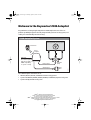
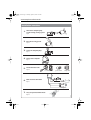
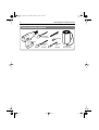
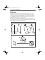
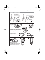
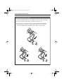
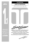
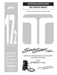
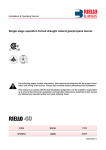
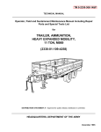
87040_5.book Page 1 Monday, April 30, 2007 5:58 PM
SmartPilot
S1000 Autopilot
Installation Guide
Document Number: 87040-5
Date: March 2007
87040_5.book Page 2 Monday, April 30, 2007 5:58 PM
Welcome to the Raymarine S1000 Autopilot
Congratulations on having bought a Raymarine S1000 Autopilot. This state-of-the-art
product is specifically designed to be easily integrated with your boat’s steering system, and
enable you to automatically control the steering.
S1000 Autopilot System
Existing hydraulic steering system
S100 REMOTE
S100 Remote
MODE
STANDBY
PILOT
Course
computer
GPS input
Pump control
Alarm signal
Autopilot
pump
Safety
alarm
D7501-1
The S1000 requires
GPS data (SeaTalk or
NMEA compatible),
to operate correctly
The S1000 Autopilot is intended for use in:
• HC5345, HC5347, HC5348, and HC5358 SeaStar steering systems.
• Systems with HC4600, HC4645, HC4647, HC4648, and HC4658, BayStar steering rams.
• Systems with Hynautic K6 steering rams.
SeaTalk® is a Registered Trademark of Raymarine
SeaStar® is a Registered Trademark of Teleflex Incorporated
BayStar is a Trademark of Teleflex Incorporated
NMEA® is a Registered Trademark of the National Marine Electronics Assocociation
All other trademarks used in this document are acknowledged.
© Copyright Raymarine UK Limited 2006
87040_5.book Page 1 Monday, April 30, 2007 5:58 PM
S1000 Autopilot Installation Guide
1
Installation overview
1.
Connect the autopilot pump
to your existing steering system.
Page 9
3.
4.
5.
Bleed the steering system.
Page 12
Secure the autopilot pump.
Page 16
Fit the course computer.
Page 17
Fit miscellaneous items
Page 18
S100 Remote
6.
7.
In-line
power switch
Safety alarm
Make electrical connections
Page 21
Carry out post installation checks
Page 28
D7583-1
2.
87040_5.book Page 2 Monday, April 30, 2007 5:58 PM
2
S1000 Autopilot Installation Guide
This guide
Before starting to install your S1000 Autopilot, please take time to read this guide. In particular, please take note of the safety and electromagnetic compatibility (EMC) information at the
end of this guide.
WARNING:
This product must be installed and operated in accordance with the
Raymarine instructions provided. Failure to observe this could
result in personal injury, damage to the boat and/or poor product
performance.
The installation procedures are described in a rational sequence, but because of variations in
boat design, space available etc, you may need to adapt the sequence to suit your particular
circumstances.
Before you start fitting your S1000 Autopilot, we recommend you:
• Unpack your S1000 Autopilot and check that all parts are present.
• Plan your S1000 Autopilot installation so that you fit the components in the best possible
locations.
Important note
The S1000 Autopilot must receive position information from a suitable GPS in
order to function correctly. GPS systems compatible with SeaTalk or NMEA or
both, are suitable. If you need advice as to which GPS to use, please contact
your Raymarine dealer.
87040_5.book Page 3 Monday, April 30, 2007 5:58 PM
S1000 Autopilot Installation Guide
3
What you need
Parts supplied
Elbow fitting, x 4
Autopilot Pump
Straight fitting x 2
Anti-vibration mounts x 2
'T' fitting x 2
High pressure
steering hoses
(x 2)
Low pressure
transparent
bleeding hose
Nitrile gloves
Wrench 12 mm AF x 19 mm AF
Drill 3.4 mm
Course Computer
Safety alarm
S100 REMOTE
MODE
STANDBY
Drain cups
PILOT
Fill cups
Belt clip assembly
S100 Remote & 2 x cradles
Connector block
1 pint (0.5 liter)
hydraulic fluid
Lanyard
Power cable
In-line power
switch
Ferrite
D7330-2
Data cable
Miscellaneous
cable ties
87040_5.book Page 4 Monday, April 30, 2007 5:58 PM
4
S1000 Autopilot Installation Guide
Tools & materials required
Pencil
Screwdriver,
No. 2 Pozidriv
Countersink
bit
Screwdriver,
medium,
flat blade
Screwdriver,
small,
flat blade
Absorbent,
disposable wipes
D7331-1
Drill
87040_5.book Page 5 Monday, April 30, 2007 5:58 PM
S1000 Autopilot Installation Guide
5
Planning
In order to make the installation as trouble free as possible, we strongly recommend you
spend adequate time planning the best locations for your autopilot components. This is
particularly important when considering the position of the autopilot pump, as hydraulic
hoses are supplied in fixed lengths, so there are some limitations on the positioning of the
autopilot pump with respect to the boat’s helm pump.
If you have internet access, please view the installation video on line at www.raymarine.com.
Before you disturb your hydraulic steering system, we strongly recommend that you consult
the manufacturer and read the steering system manuals.
Locating the course computer
5˚
5˚
5˚
5˚
5˚
5˚
5˚
At least 3 ft (1 meter)
D7552-1
5˚
87040_5.book Page 6 Monday, April 30, 2007 5:58 PM
6
S1000 Autopilot Installation Guide
Locating autopilot pump
Autopilot pump to be lower
than helm pump.
Install in a dry location.
Provide protection
from physical
damage.
Res
e
rv
o
Bleed
S
ir
c
re
w
Po
R es
e
rv
o
rt
Bleed
S
ir
c
re
w
Po
rt
Do not fit in engine compartments, near
fuel tanks or in any other area where fuel
vapor is likely.
Mount pump location either
horizontally or with connector end up.
Do not mount pump with connector
end down.
D7350-1
No sharp bends, kinks or
chafing of tube.
87040_5.book Page 7 Monday, April 30, 2007 5:58 PM
S1000 Autopilot Installation Guide
7
Using the hydraulic hoses
Three, pre-assembled hydraulic hoses are supplied. Two of these are dark-colored, high
pressure steering hoses and the third is a transparent low-pressure hose.
The transparent hose is intended to help you check for air bubbles when bleeding the
system and must be used only to connect the autopilot pump reservoir to the lower
connector on the helm pump. It must NOT be used anywhere else in the system.
e
Res
Bleed
S
c
w
rv
o
re
ir
Po
rt
e
Res
Bleed
c
S
c
w
rv
o
ir
re
w
rv
o
re
e
Res
Bleed
S
ir
D7553-2
Po
rt
Po
rt
87040_5.book Page 8 Monday, April 30, 2007 5:58 PM
8
S1000 Autopilot Installation Guide
Sealing hydraulic joints
CAUTION:
Do not use sealing tape on any part of a hydraulic system, as this can
disintegrate and the resulting particles can cause blockages in the
hydraulic system.
Tapered thread
Do not apply sealant to
hose connection thread.
Note: The hydraulic fittings supplied with the autopilot pump have sealant preapplied to the tapered threads. You only need to apply sealant to any extra joints
you may obtain. The recommended sealant for doing this, is Loctite 542.
D7545-1
Thread for hose
connection
Installing tapered thread fittings
1.
Hand tighten
2.
CAUTION:
Do not exceed 13 ft/lbs
(17.6 Nm) torque.
1.5 turns
From hand tight, use a wrench to tighten the joint a
further 1.5 turns. This should make it leakproof.
CAUTION:
Do not exceed 13 ft/lbs (17.6 Nm) torque.
DO NOT EXCEED 2.5 TURNS in total, from
hand tight.
To change the orientation of the joint to align it with the
hose, further tighten the joint, to a maximum of one
further turn, until the joint is facing the required
direction.
D7546-1
3.
87040_5.book Page 9 Monday, April 30, 2007 5:58 PM
S1000 Autopilot Installation Guide
9
Installation procedures
1. Connecting the autopilot pump
O
Connecting the autopilot pump, sheet 1
WARNING:
Do not allow hydraulic fluid to come into contact with your skin.
Wear the protective nitrile gloves provided when working with
hydraulic fluid.
WARNING:
A sudden release of pressure from a hydraulic system could result in
personal injury. Before disconnecting any part of a hydraulic
steering system, safely release any pressure in accordance with the
manufacturer’s instructions.
WARNING:
The autopilot pump is not suitable for use in the vicinity of
engines, fuel tanks or in any other area where fuel vapor is likely
to be present.
CAUTION:
Do not use the transparent hose for connecting any part of the
steering system other than between the autopilot pump reservoir
and the lower connector on the helm pump.
1. Secure the required hydraulic joints
(elbow or straight) into the autopilot
pump, as described under Installing
tapered thread fittings.
2. Connect the hydraulic hoses to the
autopilot pump. Ensure the transparent
hose is connected to the reservoir
connector.
Reservoir
connector
Starboard
connector
e
Res
Bleed
S
c
w
rv
o
re
ir
Po
rt
Res
e
rv
o
S
ir
c
re
w
rt
Po
Port
connector
D7345-1
Bleed
87040_5.book Page 10 Monday, April 30, 2007 5:58 PM
10
S1000 Autopilot Installation Guide
0
Connecting the autopilot pump, sheet 2
3. Set steering to dead ahead
and do not move it until
instructed.
4. Remove & retain the helm pump
breather cap.
5. Remove & retain the plug from the
helm pump lower connector, and
drain the fluid into one of the cups
provided. Discard the drained fluid in
accordance with local regulations.
reassembly, then disconnect both ram
hoses & straight connectors from the
helm pump.
Using the Installing tapered thread fittings
procedure, fit 'T' connectors to the helm pump
port and starboard connectors, and a straight
connector to the helm pump lower connector.
D7483-1
D7483-2
7.
6. Label the port ram hose to aid future
87040_5.book Page 11 Monday, April 30, 2007 5:58 PM
S1000 Autopilot Installation Guide
11
Connecting the autopilot pump, sheet 3
8. Connect hydraulic steering hoses from
autopilot pump Port and Starboard
connectors to the Port and Starboard
connectors on the helm pump, so that
Port connects to Port, and Starboard
connects to Starboard .
9.
Re-connect the ram hoses to the
appropriate helm pump 'T' connectors.
to steering
ram
e
Res
Bleed
S
c
w
rv
o
re
ir
Po
rt
e
Res
Bleed
S
c
w
rv
o
re
ir
Po
rt
10. Connect the transparent hose from autopilot pump reservoir hose to the
straight connector at the helm pump lower connector.
This completes the connection of
the autopilot pump.
Now bleed the steering system.
e
Res
Bleed
S
c
w
rv
o
re
ir
D7484-2
Po
rt
87040_5.book Page 12 Monday, April 30, 2007 5:58 PM
12
S1000 Autopilot Installation Guide
2. Bleeding the steering system
WARNING:
Do not allow hydraulic fluid to come into contact with your
skin. Wear the protective nitrile gloves provided when
working with hydraulic fluid.
Connecting the autopilot pump will introduce air into the steering system, making it feel
‘spongy’ and ‘lumpy’ to operate. To return the steering system to smooth operation, use the
procedure given here to bleed the air from the system.
Bleed procedure, sheet 1
1. Top up the helm pump with hydraulic fluid.
2. Loosen the autopilot
pump bleed screw 2 full
turns.
e
Res
Bleed
S
c
w
rv
o
re
ir
D7336-1
Po
rt
87040_5.book Page 13 Monday, April 30, 2007 5:58 PM
S1000 Autopilot Installation Guide
13
Bleed procedure, sheet 2
3. Using a suitable screwdriver, turn the
autopilot pump shaft so that the flat on the
shaft is toward the PORT side of the pump.
4. SLOWLY turn the wheel counter-clockwise and observe
the bubbles in the transparent tube. Keep the helm
pump reservoir topped up while doing this. Keep
turning the wheel counter-clockwise until there are no
more bubbles i.e. so the hydraulic fluid in the
transparent tube is clear.
c
re
w
ir
ir
Po
rt
D7339-2
w
rv
o
re
rv
o
e
Res
Bleed
c
e
Res
Bleed
S
S
Po
rt
87040_5.book Page 14 Monday, April 30, 2007 5:58 PM
14
S1000 Autopilot Installation Guide
Bleed procedure, sheet 3
5. Using
a suitable screwdriver, turn the autopilot
pump shaft so that the flat on the shaft is toward
the starboard (STBD) side of the pump.
6. SLOWLY turn the wheel clockwise and observe the bubbles
in the transparent tube. Keep the helm pump reservoir
topped up while doing this. Keep turning the wheel
counter-clockwise until there are no more bubbles i.e. so
the hydraulic fluid in the transparent tube is clear.
c
re
w
ir
ir
Po
rt
D7337-2
w
rv
o
re
rv
o
e
Res
Bleed
c
e
Res
Bleed
S
S
Po
rt
87040_5.book Page 15 Monday, April 30, 2007 5:58 PM
S1000 Autopilot Installation Guide
15
Bleed procedure, sheet 4
7. Top up the hydraulic fluid.
Correct fluid level
Helm pump
8. Turn the autopilot pump bleed screw, fully clockwise, and hand-tighten it.
e
Res
Bleed
S
c
w
rv
o
re
ir
Po
rt
9. Replace the helm pump breather cap.
D7486-1
This completes the
bleed procedure.
Now secure the pump.
87040_5.book Page 16 Monday, April 30, 2007 5:58 PM
16
S1000 Autopilot Installation Guide
3. Securing the pump
Securing the pump
1.
Place the pump at the intended
location and mark holes for the
fixing screws.
3.
Countersink the pilot holes to prevent
damage to the mounting surface.
2.
Drill two 1/8" (3.4 mm) pilot holes
for the fixing screws.
4.
Slide the anti-vibration mounts onto
the pump bracket feet, then secure
the pump with the screws provided.
e
Res
Bleed
S
c
w
rv
o
re
ir
Po
rt
e
Res
Bleed
S
c
w
rv
o
re
ir
Po
rt
D7488-2
When the autopilot pump is
secure, fit the course computer.
87040_5.book Page 17 Monday, April 30, 2007 5:58 PM
S1000 Autopilot Installation Guide
17
4. Fitting the course computer
Securing course computer
1. Mark holes for fixing screws.
2. Drill two 1/8" (3.4 mm) pilot holes
for fixing screws.
3. Countersink the pilot holes to prevent
damage to the mounting surface.
4. Partially screw in the screws provided,
then slot the course computer onto the
screws, and tighten screws.
D7338-1
The course computer is now secure.
87040_5.book Page 18 Monday, April 30, 2007 5:58 PM
18
S1000 Autopilot Installation Guide
5. Fitting miscellaneous items
Safety alarm
Locating
Securing
1. Mark holes for fixing screws.
2. Drill two 1/8" (3.4 mm) pilot holes.
3. Countersink the pilot holes to prevent
4. Secure the safety alarm with the
screws provided.
D7607-1
damage to the mounting surface.
Fitting batteries in S100 Remote
When replacing, use only high-quality
alkaline, AAA size batteries.
D7504-2
2 x AAA batteries (supplied).
87040_5.book Page 19 Monday, April 30, 2007 5:58 PM
S1000 Autopilot Installation Guide
19
Fitting S100 Remote cradle
At fixed position
1. Mark holes for the fixing screws.
On belt clip
1.
2. Drill three 1/8" (3.4 mm) pilot
holes for the fixing screws.
2.
3.
3. Countersink the pilot holes to
prevent damage to the mounting
surface.
To separate cradle from clip
D7683-1
4. Secure the cradle.
ck
Cli
87040_5.book Page 20 Monday, April 30, 2007 5:58 PM
20
S1000 Autopilot Installation Guide
In-line power switch
Locating
Fit the in-line power switch in a
readily-accessible location.
Securing
1.
2.
Cut 11/16" (18 mm)
1/ inch
5
(5 mm)
maximum
Ensure the protrusion on the
switch barrel goes fully into
the mounting hole.
3.
4.
D7591-1
5.
[
When all items have been fitted,
connect up the system electrics.
87040_5.book Page 21 Monday, April 30, 2007 5:58 PM
S1000 Autopilot Installation Guide
21
6. Electrical connections
Overview
Summary
WARNING:
Before making electrical connections to any part of the S1000
system, ensure the power source for the system is switched off.
Course Computer
e
Res
Bleed
S
c
w
rv
o
re
ir
Po
rt
RF ground
Autopilot
Pump
See Diagram A
See Diagram B
In-line power switch
See Diagram B
NMEA Spur
Alarm
SeaTalk
See Diagram C
& Diagram D
See Diagram C
See Diagram C
D7522-1
Data
cable
87040_5.book Page 22 Monday, April 30, 2007 5:58 PM
22
S1000 Autopilot Installation Guide
Connecting wires
When you need to join wires, use the either the supplied Scotchlock connectors or terminal
block, as appropriate.
D7547-1
Note: Scotchlock connectors are suitable for joining thin, data wires. They are NOT suitable for
connecting the safety alarm.
S1000 Autopilot Grounding
The S1000 Autopilot system requires an RF ground connection to be made, to ensure
complete conformance with the EU regulations requirements AFTER installation. The RF
ground connection is also essential to maintain the electromagnetic performance of the
system in all installations, regardless of local regulations requirements (world wide).
Failure to provide an RF ground when the S1000 Autopilot is installed could result in a
degraded electromagnetic performance and may affect the operation of the system.
The recommended MINIMUM requirement for an RF ground lead is:
• Flat, tinned copper braid, 0.25 inch (6.5 mm) width minimum. Equivalent stranded wire
diameter 0.16 inch (4 mm)
87040_5.book Page 23 Monday, April 30, 2007 5:58 PM
S1000 Autopilot Installation Guide
23
Diagram A: Connecting RF ground - preferred method
Course computer
S1000 Autopilot
0191O
Product Code: A18107
POWER
PUMP
FCC ID PJ5S1000
IC: 4069B-S1000
Raymarine Ltd
Portsmouth PO3 5TD England
If the boat does not have a ground plate, use the alternative method
shown in the following diagram, to connect the RF ground.
Boat hull
RF Ground Plate
Alternative method
Note: Use this method of connecting the
terminal, ONLY if the boat does
not have an RF grounding plate.
When using this method, do NOT connect the
terminal to any other point.
Course computer
S1000 Autopilot
0191O
Product
Code: A18107
A18107
Product Code:
POWER
PUMP
FCC ID PJ5S1000
IC: 4069B-S1000
Raymarine Ltd
Portsmouth PO3 5TD England
D7539-2
Now connect the power &
the autopilot pump.
87040_5.book Page 24 Monday, April 30, 2007 5:58 PM
24
S1000 Autopilot Installation Guide
Diagram B: Connecting power & autopilot pump
Course computer
S1000 Autopilot
0191O
Product Code: A18107
POWER
PUMP
FCC ID PJ5S1000
IC: 4069B-S1000
Raymarine Ltd
Portsmouth PO3 5TD England
Brown
Integral
10 A fuse
Black
12 V
Power supply
Blue
Integral
ferrite
Red
Autopilot pump
Now make the necessary
Data Cable connections.
D7541-1
In-line
power switch
87040_5.book Page 25 Monday, April 30, 2007 5:58 PM
S1000 Autopilot Installation Guide
25
Diagram C: Connecting the Data Cable
Course Computer
GPS requirement
The S1000 must receive GPS information to
function correctly. Use the Data Cable supplied,
to connect the Course Computer to a GPS, using
either of the following methods:
1. To a Raymarine GPS via SeaTalk connections.
2. To a Raymarine GPS via NMEA spur.
3. To a non-Raymarine GPS via NMEA spur.
Data
cable
NMEA connector (not
supplied), from GPS
NMEA Spur
When connecting NMEA data from an external source, always
connect via the NMEA spur on the Data Cable. Do NOT connect
NMEA data from an external source directly to the connector on
the Course Computer.
For details of the NMEA Spur
connections, refer to Diagram D
Each time power is applied to an S1000 Autopilot connected to a
Raymarine GPS (via NMEA or SeaTalk), the S1000 will set the GPS
filtering to WEAK.
Purple
White
Connector
block
Red
Black
Safety
alarm
Yellow: SeaTalk Data
Red: SeaTalk +12 V
Black: SeaTalk 0 V
SeaTalk
If you want to connect to an external SeaTalk system, ensure each of these
SeaTalk wires connects to the wire of the same color in the external system.
When you have completed the electrical connections,
secure the wires at the Course Computer.
D7549-1
Clip ferrite to
Data Cable,
as close to
the connector
as possible
87040_5.book Page 26 Monday, April 30, 2007 5:58 PM
26
S1000 Autopilot Installation Guide
Diagram D: NMEA connections
Course Computer
Using with Raymarine GPS
If a Raymarine GPS (such as the Raystar 120 or 125)
is to be connected to the S1000 Autopilot via NMEA,
the NMEA in and out, +ve and -ve lines must all be
correctly connected.
Each time power is applied to an S1000 Autopilot
connected to a Raymarine GPS (via NMEA or SeaTalk),
the S1000 will set the GPS filtering to WEAK.
Pin 1
NMEA
Connector
Pin 2
NMEA Spur
Pin 3
Pin 5
CAUTION:
Before making any changes to the Data Cable,
disconnect it from the Course Computer.
Data
cable
If it is more convenient to connect the NMEA spur to the GPS
without using the NMEA connector, you can remove the
connector and prepare the cable end as appropriate for your
preferred method of connection. Refer to the wire identification
table below, as necessary
SeaTalk & safety
alarm
connections
(see Diagram C)
Pin
number
1
2
3
5
NMEA signal
at S1000
-- ve out
+ve out
+ve in
-- ve in
Connection at
3rd party GPS
NMEA --ve receive
NMEA +ve receive
NMEA +ve transmit
NMEA --ve transmit
When you have completed the electrical
connections, secure the wires at the
Course Computer.
D7596-1
Wire
color
Brown
Green
Orange
Blue
87040_5.book Page 27 Monday, April 30, 2007 5:58 PM
S1000 Autopilot Installation Guide
27
Secure wires
Course Computer
PUMP
D7551-1
POWER
This completes the installation procedure. Now carry out the Post installation procedures
(below).
87040_5.book Page 28 Monday, April 30, 2007 5:58 PM
28
S1000 Autopilot Installation Guide
7. Post installation
When you have completed the installation of your S1000 Autopilot, use the following
procedures to:
• First carry out the Manual checks below, to check the the steering operation and check
the system for leaks, then
• Carry out the Autopilot checks & setup procedures below, to check the autopilot operates
the steering in the correct direction, and to set up the autopilot correctly.
Manual checks
With autopilot power off, turn the wheel from hard over port, to hard over starboard. If the
steering operates satisfactorily and turns in the correct direction, proceed with the other post
installation checks.
If the steering feels uneven and/or less responsive than it was before you installed your S1000
Autopilot, you may need to bleed the entire steering system. To do this, use the purge
procedure at the following web address:
http://www.seastarsteering.com/OUTBOARD/oboard.htm?../FILL_PURGE/FillPurge.htm&1
Check for leaks (sheet 1)
1. Ensure all hydraulic joints are secure, then turn
the wheel to port. When the hard over point is
reached, continue turning to port to pressurize the
port lines, until the safety valve releases. At this
point, the fluid in the port lines will be at
maximum pressure and the wheel has a 'lumpy'
feel when turned further to port.
2. With the port lines at maximum pressure, check
the port lines for leaks, paying particular
attention to the joints.
If a leak occurs, turn the wheel to starboard to
release the pressure, then repair the leak and
repeat steps 1 & 2.
D7502-1
Continue on sheet 2
87040_5.book Page 29 Monday, April 30, 2007 5:58 PM
S1000 Autopilot Installation Guide
29
Check for leaks (sheet 2)
3. Turn the wheel to starboard, and when the hard
over point is reached, continue turning to
starboard to pressurize the starboard lines, until
the safety valve releases. At this point, the fluid in
the starboard line will be at maximum pressure
and the wheel has a 'lumpy' feel when turned
further to starboard.
4. With the starboard lines at maximum pressure,
check the starboard lines for leaks, paying
particular attention to the joints.
If a leak occurs, turn the wheel to port to release
the pressure, then repair the leak and repeat
steps 3 & 4.
5. After 24 hours, re-check the steering system to
D7550-1
ensure there are still no hydraulic fluid leaks.
Autopilot checks & setup
WARNING:
Before switching on power to the course computer, make
sure that personnel are clear of the steering gear and
outboard motor(s), and that the boat is securely moored.
1. Switch on power to the S1000 system.
2. Carry out the Checking direction of turn procedure (below).
Checking direction of turn - sheet 1
Before casting off, check that the S1000 operates the boat's steering system in the correct
direction:
At the S100 Remote, hold down STANDBY for 2
seconds, to enter Setup mode.
SETUP
Continue on sheet 2
D7704-1
1.
87040_5.book Page 30 Monday, April 30, 2007 5:58 PM
30
S1000 Autopilot Installation Guide
2.
Hold down < and > in turn, and as each of these is pressed, ensure that the outboard
motor(s) turn(s) to give the correct direction of steer.
3.
If the outboard motor(s) does/do not move correctly, DO NOT USE THE BOAT. At the
S100 Remote, hold down STANDBY for 2 seconds to leave Setup mode and return to
Standby mode, then check that the S1000 components have been installed correctly. In
particular, check that the autopilot pump wiring and hydraulics are connected
correctly.
D7705-2
Checking direction of turn - sheet 2
87040_5.book Page 31 Monday, April 30, 2007 5:58 PM
S1000 Autopilot Installation Guide
Specifications
System
Approved by: FCC (USA), CE (Europe), IC (Canada)
Autopilot pump
Current consumption: 4 A at 100 psi (69 kP), 7 A at 500 psi (3449 kP)
Dimensions: 6.5 in (165 mm) x 2.5 in (65 mm) x 3.2 in (82 mm)
Weight: 3 lbs (1.4 kg)
Course computer
Voltage: 10 V dc to 16 V dc
Current consumption: 4 A nominal, with autopilot pump running
Dimensions: 6.5 in (165 mm) x 6.7 in (170 mm) x 1.73 in (44 mm)
Data In/Out: SeaTalk, NMEA 0183
S100 Remote
Voltage: 3 V, supplied by two internal, ‘AAA’ batteries.
Dimensions: S100 Remote only: 101 mm x 60.5 mm x 35 mm
Remote in cradle:103 mm x 66 mm x 44 mm
Waterproofing: IPX 6 and IPX 7
Hydraulic fittings
Tapered thread: ¼ NPT (National Pipe Thread)
Hose connection thread: 9/16 UNEF (Unified Extra Fine)
Hydraulic fluid
Recommended Type: SeaStar/BayStar Marine Steering Fluid
Other suitable Types: Texaco HO15
Shell Aero 4
Esso Univis N15
Chevron Aviation Fluid A
Mobil Aero HFA
Fluids meeting MIL H5606 specifications
31
87040_5.book Page 32 Monday, April 30, 2007 5:58 PM
32
S1000 Autopilot Installation Guide
General Information
Safety notices
WARNING: Product installation & operation
This equipment must be installed and operated in accordance with the Raymarine
instructions provided. Failure to do so could result in personal injury, damage to
your boat and/or poor product performance.
WARNING: Electrical safety
Make sure you have switched off the power supply before you start installing this
product.
Information
To the best of our knowledge, the information in this guide was correct when it went to press. However, Raymarine
cannot accept liability for any inaccuracies or omissions it may contain.
In addition, our policy of continuous product improvement may change specifications without notice. Therefore,
Raymarine cannot accept liability for any differences between the product and this guide.
EMC Installation Guidelines
All Raymarine equipment and accessories are designed to the best industry standards for use in the recreational
marine environment.
Their design and manufacture conforms to the appropriate Electromagnetic Compatibility (EMC) standards, but
correct installation is required to ensure that performance is not compromised. Although every effort has been taken
to ensure that they will perform under all conditions, it is important to understand what factors could affect the
operation of the product.
The guidelines given here describe the conditions for optimum EMC performance, but it is recognized that it may not
be possible to meet all of these conditions in all situations. To ensure the best possible conditions for EMC
performance within the constraints imposed by any location, always ensure the maximum separation possible
between different items of electrical equipment.
For optimum EMC performance, it is recommended that wherever possible:
• Raymarine equipment and cables connected to it are:
• At least 3 ft (1 m) from any equipment transmitting or cables carrying radio signals e.g. VHF radios, cables
and antennas. In the case of SSB radios, the distance should be increased to 7 ft (2 m).
• More than 7 ft (2 m) from the path of a radar beam. A radar beam can normally be assumed to spread 20
degrees above and below the radiating element.
• The equipment is supplied from a separate battery from that used for engine start. Voltage drops below 10 V in
the power supply to our products, and starter motor transients, can cause the equipment to reset. This will not
damage the equipment, but may cause the loss of some information and may change the operating mode.
• Raymarine specified cables are used. Cutting and rejoining these cables can compromise EMC performance and
must be avoided unless doing so is detailed in the installation manual.
• If a suppression ferrite is attached to a cable, this ferrite should not be removed. If the ferrite needs to be
removed during installation it must be reassembled in the same position.
87040_5.book Page 33 Monday, April 30, 2007 5:58 PM
S1000 Autopilot Installation Guide
33
Suppression Ferrites
The following illustration shows typical cable suppression ferrites used with Raymarine equipment. Always use the
ferrites supplied by Raymarine.
D3548-6
Connections to Other Equipment
If your Raymarine equipment is to be connected to other equipment using a cable not supplied by Raymarine, a
suppression ferrite MUST always be attached to the cable near the Raymarine unit.
87040_5.book Page 34 Monday, April 30, 2007 5:58 PM
34
Raymarine UK Ltd,
Quay Point,
Northarbour Road
Portsmouth,
Hampshire PO6 3TD,
United Kingdom.
Tel: +44 (0) 23 9269 3611
Fax: +44 (0) 23 9269 4642
www.raymarine.com
S1000 Autopilot Installation Guide
Raymarine Inc,
21, Manchester Street,
Merrimack,
New Hampshire 03054-4801,
USA.
Tel: +1 603.881.5200
Fax: +1 603.864.4756
www.raymarine.com