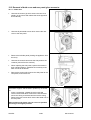
1
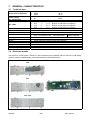
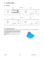
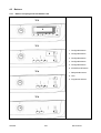
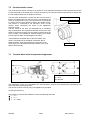
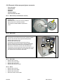
SERVICE MANUAL DRYERS Condenser dryer with electronic control system © ELECTROLUX ZANUSSI S.p.A. Spares Operations Italy Corso Lino Zanussi, 30 I - 33080 PORCIA /PN (ITALY) Fax: + 39 0434 394096 Edition: 2006-10 25 Publication No. 599 38 46-21 EN ENV 06 Stylings TC2 – TC3 – TC4 – TC6 Production: PLY – Siewierz (PL) SOI/ADL 1/57 599 38 46-21 INDICE Purpose of this Manual............................................................................................................................... 4 IMPORTANT .............................................................................................................................................. 4 2.1 Installation............................................................................................................................................. 4 3 GENERAL CHARACTERISTICS ............................................................................................................... 5 3.1 Technical data ...................................................................................................................................... 5 3.2 Electronic boards .................................................................................................................................. 5 4 CONTROL PANEL ..................................................................................................................................... 6 4.1 Stylings ................................................................................................................................................. 6 4.2 Programme selector ............................................................................................................................. 6 4.3 Buttons.................................................................................................................................................. 7 4.3.1 Buttons on stylings with and without LCD.................................................................................... 7 4.4 Symbols on stylings with LCD .............................................................................................................. 8 4.5 Humidity level (on some models) ......................................................................................................... 9 1 2 4.6 Child protection (on some models) 4.7 Delicate ½ power (on some models) 4.8 No buzzer button ................................................................................................ 9 ............................................................................................. 9 ......................................................................................................................... 10 4.9 Delayed start button .................................................................................................................... 11 4.10 “START / PAUSE” button ............................................................................................................... 11 4.11 Adjusting the level of conductivity (on some models) .................................................................... 12 4.11.1 Procedure................................................................................................................................... 12 4.12 Warning LEDs ................................................................................................................................ 13 5 Description of operation of the appliance................................................................................................. 14 5.1 Operation of a cycle............................................................................................................................ 14 5.2 Operation in PAUSE mode................................................................................................................. 14 5.3 Operation in DELAYED START mode ............................................................................................... 15 5.4 Power failure....................................................................................................................................... 15 6 STRUCTURAL AND FUNCTIONAL CHARACTERISTICS ..................................................................... 16 6.1 Drying circuit ....................................................................................................................................... 16 6.2 Structural characteristics .................................................................................................................... 17 6.3 Drum ................................................................................................................................................... 18 6.4 Air seals and drum shaft supports ...................................................................................................... 18 6.5 Hydraulic circuit (versions with canister in upper section).................................................................. 19 6.6 Drum rotation ...................................................................................................................................... 19 7 ELECTRICAL COMPONENTS ................................................................................................................ 20 7.1 EDR2000 Electronic control ............................................................................................................... 20 7.1.1 Electronic board functions.......................................................................................................... 20 7.1.2 General structure of board memory........................................................................................... 21 7.2 Conductimetric sensor........................................................................................................................ 22 7.3 Terminal block with incorporated suppressor..................................................................................... 22 7.4 Heater unit .......................................................................................................................................... 23 7.5 NTC sensor......................................................................................................................................... 23 7.6 Motor................................................................................................................................................... 24 7.7 Canister filling pipe (models with canister in upper section) .............................................................. 24 7.8 Door interlock...................................................................................................................................... 25 8 ELECTRICAL CIRCUIT............................................................................................................................ 26 9 DIAGNOSTICS SYSTEM......................................................................................................................... 27 9.1 Access to diagnostics ......................................................................................................................... 27 9.2 Exiting the diagnostics system ........................................................................................................... 28 9.3 Selector positions for diagnostics on appliances with styling TC2 – TC3 – TC4 ............................... 29 9.4 Selector positions for diagnostics on appliances with styling TC6 .................................................... 31 10 ALARMS ............................................................................................................................................. 32 10.1 Displaying the alarms to the user................................................................................................... 32 10.1.1 Alarm display during normal operation ...................................................................................... 32 10.2 Reading the alarm codes ............................................................................................................... 32 10.2.1 Displaying the alarm code on models TC2 – TC3 ..................................................................... 32 10.2.2 Displaying the alarm code on models TC4 – TC6 ..................................................................... 32 10.3 Cancelling the last alarm memorized ............................................................................................. 33 10.4 Notes concerning certain alarm codes........................................................................................... 33 10.5 Table of alarms............................................................................................................................... 34 11 NO ACCESS TO DIAGNOSTICS PROGRAMME ............................................................................. 37 11.1 No LEDs on the display board light................................................................................................ 37 SOI/ADL 2/57 599 38 46-21 Some of the LEDs on the display board light................................................................................. 38 11.2 12 ACCESSIBILITY TO COMPONENTS ................................................................................................ 39 12.1 Door................................................................................................................................................ 39 12.1.1 Door ........................................................................................................................................... 39 12.1.2 Fluff filter fitted inside door......................................................................................................... 39 12.1.3 Fluff filter support ....................................................................................................................... 39 12.1.4 Lower fluff filter........................................................................................................................... 39 12.1.5 Drum light (if featured) ............................................................................................................... 39 12.2 Work top ......................................................................................................................................... 40 12.2.1 Front brush of conductimetric sensor ........................................................................................ 40 12.2.2 Canister...................................................................................................................................... 40 12.2.3 Control panel support and Control panel ................................................................................... 41 12.2.4 Main electronic board................................................................................................................. 42 12.2.5 Selector pin ................................................................................................................................ 42 12.2.6 Selector knob ............................................................................................................................. 42 12.2.7 Button springing ......................................................................................................................... 42 12.2.8 Button and visor unit on models TC2......................................................................................... 42 12.3 Removal of both cover and rear panel gives access to: ................................................................ 43 12.3.1 Heater unit.................................................................................................................................. 43 12.3.2 Removal of the left-hand side panel gives access to: ............................................................... 44 12.3.3 Floating switch ........................................................................................................................... 44 12.3.4 Float ........................................................................................................................................... 45 12.3.5 Pump.......................................................................................................................................... 45 12.3.6 Door interlock............................................................................................................................. 46 12.4 Removal of the right-hand side panel gives access to:.................................................................. 47 12.4.1 Condensatore motore ................................................................................................................ 47 12.4.2 NTC Sensor ............................................................................................................................... 48 12.4.3 Rear air duct cover (hot air circulation)...................................................................................... 48 12.4.4 Rear air duct cover (cold air circulation) .................................................................................... 48 12.4.5 Drum rotation motor ................................................................................................................... 49 12.5 Removal of the front panel gives access to: .................................................................................. 50 12.5.1 Capacitor (Heat exchanger)....................................................................................................... 50 12.5.2 Front flap .................................................................................................................................... 50 12.5.3 Plinth .......................................................................................................................................... 51 12.5.4 Door microswitch ....................................................................................................................... 51 12.6 Removal of the rear panel gives access to: ................................................................................... 52 12.6.1 Rear brush (conductimetric sensor)........................................................................................... 52 12.6.2 Rear panel.................................................................................................................................. 52 12.6.3 Drive belt .................................................................................................................................... 52 12.6.4 Drum .......................................................................................................................................... 52 12.6.5 Duct............................................................................................................................................ 53 12.6.6 Duct rollers ................................................................................................................................. 53 12.6.7 Front and rear seals................................................................................................................... 53 13 REVERSIBILITY OF THE DOOR....................................................................................................... 54 14 FINAL TESTING OF DOOR CLOSURE............................................................................................. 56 SOI/ADL 3/57 599 38 46-21 1 Purpose of this Manual The purpose of this Service Manual is to provide service engineers who already have the basic knowledge necessary to repair dryers with information concerning condenser dryers with electronic control systems ENV 06 with anti-crease system CRM produced in the factory of Siewierz (Poland). The control system features two PCBs: a main one featuring an integrated selector and LCD display, supplied already mounted and tested by the building factory and a control board of the CRM system. This Service Manual describes the following aspects: • • • • • General characteristics Control panel and drying programmes Technical characteristics Accessibility Diagnostics guide 2 IMPORTANT Ö Repairs to electrical appliances must be carried out only by qualified service engineers. Ö Before touching internal components, always remove the plug from the power socket. WARNING 2.1 Installation Ö The appliance must be installed on a perfectly level surface in order to ensure that the condensed water flows correctly into the tank. Ö The feet must NOT be removed. The gap between the bottom of the dryer and the floor is essential to prevent overheating. SOI/ADL 4/57 599 38 46-21 3 GENERAL CHARACTERISTICS 3.1 Technical data Dimensions of appliance Power supply No. pushbuttons No. LEDs Type of display Buzzer Serial port Programme selector Drying system Humidity control Motor Power of heater unit Temperature control Capacity of canister Canister fill pump 3.2 Height: 85 cm Width: 60 cm Depth: 58 cm Volt: 220-240 Hz: 50/60 7⇒ (TC2) 6⇒ (TC3) 5⇒ (TC5) 3⇒ (TC6) TC2 ⇒ 3 + 1 bicolour on start button (red green) TC3 ⇒ 9 + 1 bicolour on start button (red green) TC4 ⇒ 14 + 1 bicolour on start button (red green) TC6 ⇒ 8 + 1 bicolour on start button (red green) LCD on TC2 – TC3 models Buzzer incorporated in the PCB DAAS-EAP protocol up to 230400 baud TC2 – TC3 – TC4 ⇒ 15 positions With ON/OFF switch integrated TC6 ⇒ 21 positions timer 25 temperometric Condensation of humidity by heat exchanger Conductimetric sensor Single-phase asynchronous motor with capacitor Version 220-240V 2200 W 1400 W + 800 W NTC sensor Condensation tank 4l approx. Synchronous motor Electronic boards The electronic control system consists of a main PCB having an integrated selector and also a LCD display (in some models) supplied already mounted and tested by the building factory. Main PCB TC2 TC3 TC4 / TC6 SOI/ADL 5/57 599 38 46-21 4 CONTROL PANEL 4.1 Stylings With LCD TC2 TC3 With LED TC6 TC4 4.2 Programme selector The 15-position programme selector onTC2 – TC3 – TC4 models and 21/25 positions on TC6 models (with incorporated ON/OFF switch) is built into the board. The symbols represent the different possibilities of drying the various fabrics COTTON SYNTHETICS SILK and WOOL. All positions can be configured depending on the model. SOI/ADL 6/57 599 38 46-21 4.3 4.3.1 Buttons Buttons on stylings with and without LCD TC2 7 8 9 1 4 3 2 5 6 TC3 1. Configurable button 8 7 2. Configurable button 9 3. Configurable button 1 2 3 4 6 4. Configurable button 5. Configurable button 6. START/PAUSE button TC4 7. Delayed start button 8. LCD 7 9. Programme selector 9 2 3 4 6 TC6 9 2 SOI/ADL 6 3 7/57 599 38 46-21 4.4 Symbols on stylings with LCD The various icons and writings represented on the LCD display are displayed depending on the programme and on the programme phase being executed. Delayed start Drying phase Cooling phase Anti-crease phase Child protection (key lock) Delicate Buzzer Time-to-end / Alarm code SOI/ADL 8/57 599 38 46-21 4.5 Humidity level (on some models) By pushing this button it is possible to select one of the three different final drying levels of the programme represented by the following symbols: • • • MIN (the time varies depending on the programme) MED (the programme is prolonged by 3 minutes) MAX (the programme is prolonged by 6 minutes) 4.6 Child protection (on some models) By pushing simultaneously for 5 seconds the buttons 4 and 5 on TC2 models 3 and 4 on TC3 models the child protection is activated, all buttons are disabled and no modification is allowed. To deactivate this protection, push the same buttons again. 4.7 Delicate ½ power (on some models) The dryer features a heating unit which consists of two heating elements, and according to the versions the powers are different. Pressing once the button, the electronic control excludes the less powerful branch of the heating unit and simultaneously the LED lights up to indicate that the option has been selected; pressing it again, the LED switches off to indicate that the option has been deactivated and the previously excluded branch will be powered again during the cycle execution. SOI/ADL 9/57 599 38 46-21 4.8 No buzzer button Option to be selected when the dryer is in selection mode (set-up). Press this button to exclude the buzzer: the exclusion is signalled by the switching on of the LED or of the icon, depending on the models. To reactivate the option, press the button again. Even if the buzzer is excluded, the alarm acoustic signalling remains active. Exclusion of the buzzer (not only for the affected cycle) Selection to be made during the selection phase (set-up): On TC2 models push buttons 2 and 3 simultaneously for five seconds: the icon representing the buzzer will light up and a beep will be emitted. On TC3 models push buttons 2 and 3 simultaneously for five seconds: the LED representing the buzzer will light up and a beep will be emitted. On TC4 models push buttons 1 and 2 simultaneously for five seconds: the LED representing the buzzer will light up and a beep will be emitted. On TC6 models push buttons 1 and 2 simultaneously for five seconds and a beep will be emitted. To reactivate the buzzer, push the key combination above described again till the buzzer emits a “Beep”. Attention: on TC6 models no acoustic signal will be emitted. SOI/ADL 10/57 599 38 46-21 4.9 Delayed start button Pressing this button it is possible to select, during the programme selection phase, a delayed start. On TC2 and TC3 models, the time varies up to 12 hours; the time is displayed in the Display. Every time the button is pressed, the time displayed increases: Ö Ö Ö For the first two hours, the step is about half an hour Later, the step is one hour To cancel the delay, move the selector by one position or press the button till the display is reset. On TC5 models the time varies till max. 9 hours. Push the button till the relative pilot lamp of the chosen delay lights up. This option must be selected in all models after selecting the programme and before pushing START/PAUSE. 4.10 “START / PAUSE” button Start When a drying programme is selected with the selector, the icons of the three phases (drying, cooling, anticrease) light up and the LED START/PAUSE flashes. After having selected the options, press this button to start the cycle; the relative LED remains lit. Pause If a drying cycle is being executed, pressing the START/PAUSE button, the dryer interrupts the cycle and is in PAUSE mode; the relative LED flashes. Pressing the START/PAUSE button, the drying cycle starts from the point at which it was interrupted. SOI/ADL 11/57 599 38 46-21 4.11 Adjusting the level of conductivity (on some models) The conductivity of the water used to wash the fabrics varies from zone to zone. The conductimetric sensor is calibrated to a standard value: any major variations in the level of conductivity may affect the final drying result (i.e. the washing may be too dry or too humid): These variations are more noticeable in the "slightly damp" or "iron-ready" cycles; the "cupboard dry cycles are almost entirely unaffected by variations in conductivity. The sensitivity of the conductimetric sensor can be adjusted according to the conductivity of the water. 4.11.1 Procedure • To access adjustment mode: 1. Turn the programme selector to switch on the appliance. 2. In selection mode (set-up), simultaneously press buttons 3 (Delicate) and 6 (start/pause). On TC2 and TC3 models Hold the buttons down till “C0” appears on the first 2 digits and the buzzer sounds (about 5 seconds). • Adjusting the level of conductivity: Press the 6 button sequentially (start/pause): the level of conductivity is indicated by the lighting of the horizontal hyphens of the last digit. On TC5 models Hold the buttons down till the pilot lamps placed above the buttons start to flash and one of the pilot lamps that indicate the drying phase remains on: • Adjusting the level of conductivity: Push the START/PAUSE button sequentially: the conductivity level will be indicated by the pilot lamps of the single phases. • Memorizing the new setting: 1. Simultaneously press buttons 3 (Delicate) and 6 (start/pause). 2. Hold the buttons down until the drying cycle reappears on the display and the buzzer sounds (about 5 seconds). SOI/ADL 12/57 599 38 46-21 Display Conductivity Approximate value (μS/cm) Low < 300 Medium 300 - 600 High > 600 Normally, the appliance is factory-set to the highest level; however, certain models may be configured differently. Your local water supply company can give you information concerning the conductivity of the water in your area. 4.12 Warning LEDs L1. Heat exchanger cleaning (condenser): it lights up after 80 drying cycles. To reset the cycle counter (for this function), open the door with the appliance on, extract the heat exchanger, clean it and recluse the door. L2. Filter cleaning: it lights up when the dryer has terminated the cycle to warn the user to clean the fluff filter. L3. Tank full: it lights up durino the drying cycle if the electronic circuit detects the closing of the floating microswitch and at the end of the cycle to warn the user to empty the tank. L4. Start/pause: it lights up with green flashing light when the cycle is in pause; it lights up with green fixed light when the cycle is running regularly. If there is an alarm three beeps will be emitted that will be repeated after some seconds and the LED becomes red with flashing light. SOI/ADL 13/57 L1 L2 L3 L4 599 38 46-21 5 Description of operation of the appliance When the selector is turned from OFF position to a drying programme, the icons relative to the drying phases light up and the START/PAUSE LED flashes with green light. During this phase the various options can be entered, and the corresponding LEDs will light. The lower right display shows the maximum time of drying cycle. If an option that is incompatible with the selected cycle is entered, the Buzzer sounds, the Display shows Err while the LEDs flash. Selecting one or more options the Display shows an increase or decrease of the time. If the position of the selector is changed after choosing the options, but before pressing START/PAUSE button, the options will be cancelled. 5.1 Operation of a cycle A drying cycle starts after a programme has been selected using the selector, one option (if necessary) has been selected and the START/PAUSE pushbutton has been pressed. The LED corresponding to the START/PAUSE button remains lit with green light and, at the same time, the LED corresponding to the phase currently being performed lights and the display shows the maximum drying time. The drying cycle consists of the following phases: • DRYING If the cycle is automatic, its duration will be the time necessary to remove the humidity until the desired degree of final humidity is reached (maximum cycle time 180 minutes at full power and 240 minutes at half power). If the cycle is timer-controlled, the duration will be the time selected by the user. • COOLING For timer-controlled cycles, the maximum duration of the cooling phase is 10 minutes; for automatic cycles the duration depends on the temperature inside the drum. • ANTI-CREASE The duration of the anti-crease cycle is 30 minutes. No modifications to the programmes can be entered after the drying programme has started. If the position of the selector is changed, the green LED of the START / PAUSE button starts flashing, the buzzer sounds to warn the user that an incorrect operation has been attempted and the display shows <<Err>>. If any button is pressed, the green LED of the START / PAUSE button starts flashing, the buzzer sounds to warn the user that an incorrect operation has been attempted and the display shows <<Err>>. The options can be selected only after selecting a drying programme at the beginning of the cycle, or during a cycle after pressing the START/PAUSE button. To cancel a drying cycle, it is necessary to turn the programme selector to OFF. 5.2 Operation in PAUSE mode If START/PAUSE is pressed while a drying cycle is being performed, the dryer interrupts the current cycle, the green LED of the START / PAUSE button flashes and the display shows time to end. If the selector is turned, the buzzer warns the user of the error. In this situation, only certain options can be modified, see table of OPTIONS. If the button relative to an option that cannot be selected is pressed, the buzzer sounds to warn the user of the error and the display shows <<Err>>. When START/PAUSE is pressed again, the drying cycle resumes from the point at which it was interrupted. SOI/ADL 14/57 599 38 46-21 5.3 Operation in DELAYED START mode After selecting a drying cycle, press this button to enter the delayed start option (the selected time is indicated on the display). Every time the button is pressed the delay time increases, (for the first 2 hours the time increases of half an hour, then of an hour), the maximum time that can be selected is 20 hours. To cancel this option move the selector of one position or press the button till the option is cancelled on the display. The start of the cycle is always determined by pressing the START/PAUSE button. 5.4 Power failure The table below shows how the dryer behaves in the event of a power failure during a drying cycle. Before the power failure Set-up Drying cycle Cycle paused Anti-crease phase Delayed-start cycle Delayed start cycle paused End of cycle "Canister full" alarm SOI/ADL After power is restored Set-up Pause Pause End of cycle Delayed-start cycle paused Delayed start cycle paused End of cycle "Canister full" alarm 15/57 599 38 46-21 6 STRUCTURAL AND FUNCTIONAL CHARACTERISTICS 6.1 Drying circuit Version with canister in upper section Version with canister in lower section There are two air circuits inside the dryer: the first is a warm-air circuit, which is sealed within the appliance the second is an open cold-air circuit, which circulates air from the ambient through certain sections of the appliance. In the sealed warm-air circuit, the air circulates inside the appliance: The fan (1), ducts the air through a heat exchanger (5), and then to the heater unit (2). The heater unit heats the air, which is then ducted into the drum through the perforations in the rear flange of the drum. The warm, dry air passes through the wash load, which is agitated by the rotation of the drum, and removes the humidity from the fabrics; the air, which is now warm and humid, passes then through the front aperture of the drum via the fluff filter (3) and the lower filter (4), then the air is ducted by the fan (1) to the heat exchanger (5), where the humidity is condensed. The air coming from the heat exchanger is now dry and the cycle continues as described above. The cold-air circuit (the air circulates in one side of the appliance) is not sealed. The fan (6) draws in air through an air intake on the rear of the appliance, and ducts the air to the heat exchanger (5), cooling it, after which the air is expelled on the opposite side of the heat exchanger dissipating inside the appliance and exiting from the venting grille in the plinth. The warm and cold air circuits cross inside the heat exchanger (5), which results in a thermal exchange which condenses the humidity contained in the warm air. The condensation water, which forms in the heat exchanger, is collected in a sump (7) which contains a float (9): ¾ In versions with the canister in the upper section, a pump (11) ducts the water from the sump (7) to the canister (8). When the canister is full, any overflow is collected in the canister support and returned through a tube (not shown in the figure) into the sump (7). This causes the float (9) to rise, thus actioning the microswitch (10). ¾ In versions with the canister in the lower section, the water flows by gravity from the sump (7) into the canister (8); when the canister is full, the water level in the sump (7) rises. This causes the float (9) to rise, thus actioning the microswitch (10). The electronic control system detects the closure of the microswitch, cuts off the power to the appliance and switches on a LED warning the user that the canister is full. The tank capacity is about 4 lt., which is sufficient for one drying cycle. SOI/ADL 16/57 599 38 46-21 6.2 Structural characteristics Version with canister in upper section Version with canister in lower section 1 – Work top 2 – Control panel support 3 – Control panel 4 – Fluff filter 5 – Fluff filter support 6 – Door seal 7 – Door internal frame 8 – Door external frame 9 – Rear panel cover protection 10 – Rear panel cover 11 – Rear panel 12 – Cross-member 13 – Side panel 14 – Duct 15 – Front panel 16 – Lower fluff filter 17 – Base 18 – Heat exchanger 19 – Lower canister 20 – Panel 21 – Plinth 1 – Work top 2 – Control panel support 3 – Control panel 4 – Fluff filter 5 – Fluff filter support 6 – Door seal 7 – Door internal frame 8 – Door external frame 9 – Rear panel cover protection 10 – Rear panel cover 11 – Rear panel 12 – Cross-member 13 – Side panels 14 – Upper tank 15 – Tank support 16 – Duct 17 – Front panel 18 – Base 19 – Heat exchanger 20 – Panel 21 – Plinth 22 – Front fluff filter The front panel and the side panels are in enamelled sheet metal; the rear panel is in zinc-plated sheet metal. The panels are secured to the base by self-tapping screws. The shaped carboran base houses the main components. SOI/ADL 17/57 599 38 46-21 6.3 Drum 1 – Front flange 2 – Drum housing 3 – Rear flange 4 – Drum lifters 5 - Plastic band The drum consists of two half-shells (front and rear) which are joined together by a wide plastic band (5). Separation of the drum into two parts allows the conductimetric sensor to determine the conductivity of the washing inside the drum. Parts 1, 2 and 3 are connected by crimping. The plastic lifters are secured by screws to the internal wall of the drum. The various elements which make up the drum are in sheet steel. The rear drum shaft is fitted to the rear flange using eyelet rivets. 6.4 Air seals and drum shaft supports Rear air seal 1 - Rear seal (fitted to rear panel) 2 - Drum 3 - Rear panel Rear drum support 4 – Anti-clutching washer 5 – Fixing ring (Benzing) 6 – Rear panel 7 – Drum spindle 8 – Support with bushing (fitted to the rear panel) Front drum support and air seal 9 – Drum 10 – Felt ring with tubular support 11 – Duct Lower drum support 9 – Drum 10 – Felt ring with tubular support 11 – Duct 12 – Drum support roller SOI/ADL 18/57 599 38 46-21 6.5 Hydraulic circuit (versions with canister in upper section) 1 – Pump immersed in the sump 2 – Water fill hose to canister (Red) 3 – Overflow drain hose (Transparent) 4 – Canister The condensation water is ducted from the sump (1) to the tank (4) by the pump immersed in the sump via the hose (2). When the canister is full the overflow is collected in the canister support and ducted to the sump through the hose (3). 6.6 Drum rotation 1 – Motor 2 – Belt tensioner spring 3 – Belt tensioner 4 – Belt The drum is rotated by a belt (4), which is driven by the pulley of the drum motor (1) fitted to the base; on the bearing shield there is a belt tensioner (3), which has the function of increasing the winding angle of the belt to the drum and works in conjunction with the belt tensioner spring (2). Bidirectional operation of the drum rotation is determined by the electronic board which inverts the motor power direction for brief periods. Reversal of the direction of rotation allows the clothes to unroll. During these short periods, the heater unit is switched off. The heat exchanger features a safety device which ensures that, if the panel is opened to check the heat exchanger, a microswitch disconnects the dryer from the power supply). SOI/ADL 19/57 599 38 46-21 7 ELECTRICAL COMPONENTS 7.1 EDR2000 Electronic control The electronic control consists of a main electronic board fitted into a plastic container, fixed behind the control support. On models with LCD also the display board is mounted on this container. TC2 1. Electronic board - casing 2. Cover for connectors 2 3. Cover for selector 3 4. Programme selector shaft 5. Button springing 1 4 7.1.1 5 Electronic board functions DISPLAY BOARD Pushbutton LEDs μP μP ELECTRICAL LOADS SENSORS Programme selector Buzzer MAIN ELECTRONIC BOARD Ö The electronic board receives the controls relative to the drying cycle setting through the control/display board. Ö The electronic board powers the main components: motor, pump (for dryers with canister in the upper section), heater and door interlock. Ö The board also controls the door interlock, the temperature of the air inside the dryer (using an NTC sensor), the level of humidity of the washing (using a conductimetric sensor) and the level of condensation water in the canister. Ö The programme selector and the buzzer are incorporated in the main board. SOI/ADL 20/57 599 38 46-21 7.1.2 General structure of board memory The system features an EEPROM, positioned externally to the microprocessor, which memorizes the configuration data, the description of the cycle, the status of the appliance in case of a power failure, and the alarms. μP External asynchronous serial port ROM RAM Power Failure and machine status Internal synchronous serial port EEPROM (external to the μP) Configuration of the appliance Description of the cycle ROM This area of the memory contains the "firmware" code including the functionalities of the appliance: Ö Control of electrical loads (motor, pump, heater) Ö Control of the sensors (NTC, conductimetric sensor, door switch status) Ö Control of the user interface Ö Control of the serial port Ö Control of power failures and alarms Ö Execution of the drying programme In standard-production appliances, this area is a Read-Only Memory, and thus cannot be modified. RAM This memory contains the variables, i.e. all the dynamic information used during execution of the programme: Ö Machine status Ö Cycle selected Ö Alarms The contents of this memory are cancelled each time the appliance is disconnected (by switching off or in the event of a power failure). The contents can be read using a computer connected via a DAAS interface. EEPROM The EEPROM contains data of various types: Ö Power failure and machine status, i.e. the information necessary to resume operation of the appliance after a power failure. Ö Configuration of the drying cycle: this file describes the various steps in the drying cycle for each family of appliances (vented, condenser etc.). Ö Machine configuration: the data contained in this area of memory define the configuration of the individual appliance, and are interpreted by the functional software. These files define the following: - Programmes - Number of buttons and their functions - Operation of the LEDs - Operation of the buzzer - Operational limits (voltage/frequency) - Identification of the appliance (PNC + ELC + serial number) - Heater unit power - Preferential direction of motor rotation SOI/ADL 21/57 599 38 46-21 7.2 Conductimetric sensor The conductimetric sensor consists of an electronic circuit (positioned inside the power board) and a section located externally to the board which consists of the wiring, two brushes (sensors positioned in contact with the tub shells) and the two tub shells themselves. The first brush positioned in contact with the front tub shell is fitted to a hinged support on the duct, and is connected by the wiring to the electronic circuit. The second brush is positioned in contact with the drum spindle housed in the spindle casing. This sensor is connected to the electronic circuit via the cabinet, which represents the mass of the appliance's electronic circuit. The two halves of the drum are separated by an insulating strip, and therefore the impedance between the front and rear shells (to which the sensors are connected) is infinite when the drum is empty. The impedance varies according to the wash load, the type of fabric and the degree of humidity. The impedance is between about 1MΩ and 25MΩ. This value is converted into an oscillation of between about 260Hz and 0Hz; when processed by the electronic circuit (fuzzy logic), this value determines the duration of the cycle and the final humidity. 7.3 Electronic circuit Sensors Half-shells Terminal block with incorporated suppressor A = Suppressor components L = Live N = Neutral The suppressor, which is incorporated in the terminal block, prevents radio disturbance generated by the dryer from entering the power lines. This device functions correctly only if the appliance is grounded. Checking for efficiency: Use a tester to measure the resistance across the following terminals: Ö 1–2=∞ Ö 2–3=∞ Ö 1 – 3 =~ 2MΩ SOI/ADL 22/57 599 38 46-21 7.4 Heater unit 1 – Filament heating element 2 - Ceramic supports 3 - Sheet metal casing 4 - TH1 Safety thermostat (automatic reset) 5 - TH2 Safety thermostat The heater unit consists of two wire heating elements with different powers. The two heating elements are fitted to ceramic supports, and the entire assembly is housed in a sheet metal casing. Two safety thermostats (normally closed) are positioned to one side of the casing. TH1 (automatic reset) (4) intervenes at a temperature of 92±3°C, and disconnects both heating elements. Thermostat TH2 (5) intervenes at 160°C; when the contact opens, it remains open, permanently disconnecting all the electrical components in the appliance. The heater unit is powered via two relays (RL1 and RL2) fitted to the board. Type Branch A Branch B Heater unit versions Total power (-2+ 8%): W 2400 2000 Rated voltage: V 240 230 Power (-2+ 8%): W 1400 1400 36 33 Resistance: Ω Power (-2+ 8%): W 1000 600 51 78 Resistance: Ω 2000 240 1400 36 600 85 2200 240 1400 36 800 63 IMPORTANT: In the event of a thermostat failure, the entire heater unit must be replaced! 7.5 NTC sensor The NTC sensor is fitted to the hot air fan duct. This sensor consists of a resistor contained in a metallic capsule. Its resistance decreases as the temperature increases. The electronic circuit reads the resistance (which varies with the temperature inside the dryer); when this resistance falls below a certain value, the heater unit is switched off. As the air cools, the resistance increases; when it reaches a given value, the electronic circuit re-connects the heater unit to the power supply. This occurs each time the temperature inside the dryer exceeds a given value, which varies according to the drying cycle that has been selected. 1 – NTC resistor 2 – Metallic capsule 3 – Terminals 4 – Plastic casing TEMPERATURE (ºC) 20 60 80 SOI/ADL Rated value 6050 1250 640 23/57 RESISTANCE (Ω) Maximum value 6335 1278 620 Minimum value 5765 1222 660 599 38 46-21 7.6 Motor 1 – Fan (inclined blades for cold air circulation) 2 – Belt tensioner 3 – Motor 4 – Fan (straight blades for warm air circulation) The motor group consists of a belt tensioner (2), two fan blades (1 and 4) for circulating cold and warm air respectively, fitted to the motor shaft using bolts, and a single-phase asynchronous motor (3) featuring an overheating safety cut-out. Important: when assembling the fan blades to the motor, do not reverse their positions, as this would cause incorrect air circulation inside the dryer. The efficiency of the motor can be checked by measuring the resistance across the windings: Winding A ohm 29 ~ (contacts 1-3) Winding B ohm 29 ~ (contacts 2-3) The motor is powered by the electronic board via a relay (which determines the direction of rotation) and a triac. 7.7 Canister filling pipe (models with canister in upper section) The pump is actioned by a synchronous motor with a power of about 17W. The function of the motor is to pump the condensation water from the sump to the canister. The pump, too, is powered by a triac. The resistance of the stator winding is approximately 750 Ω. SOI/ADL 24/57 599 38 46-21 7.8 Door interlock The door interlock is an electromechanical device which powers the electrical loads only when the door is correctly closed and the programme selector knob is turned (ON/OFF - closed). The interlock features a child safety device so that, in case of necessity, the door can be opened by pressing from inside the appliance. Opened door: the lever holds down the button of deviator “A”; in this position contacts 1-2 are closed. In some models they power the drum light when the main switch is off. Closing the door: the latch (1) rotates cam (2): this movement releases lever (3) and the button on the deviator “A” changes position, thus closing contacts 1-3 and powering all components of the appliance (cutting power out to the drum light) Position of connectors Pushing the door opening button: the main electronic board powers the coil; the core (1), moves the anchor (2), releasing the cam (3). The cam, rotating, moves the lever (4) which closes the contacts of the deviator “A” in position 1-2, and releases the door latch (5). Wiring diagram A = Commutator in open position contacts 1-2: 0 Ω contacts 1-3: ∞ Ω C = Door opening coil contacts 7-8: ~ 90Ω SOI/ADL 25/57 599 38 46-21 8 ELECTRICAL CIRCUIT SOI/ADL 26/57 599 38 46-21 9 DIAGNOSTICS SYSTEM In diagnostics mode, it is possible to check the operation of the appliance and to read the alarm codes. 9.1 Access to diagnostics 1. The appliance must be switched OFF. 2. Switch the appliance ON by turning the programme selector knob one position clockwise. 3. Wait until the LEDs light and the buzzer sounds, then simultaneously press the related buttons depending on the models. Important: this operation must be performed within 5 seconds! 4. Hold these buttons down until the LEDs begin to flash and the buzzer sounds. Styling TC2 Buttons 5-6 Styling TC3 Buttons 4-5 Styling TC4 Buttons 3-4 Selector in the first position clockwise Styling TC6 Buttons 2-3 SOI/ADL 27/57 599 38 46-21 IMPORTANT! ¾ The alarms remain active during component diagnostics testing. If an alarm should be displayed, turn the programme selector to the first position to exit the alarm situation, and then continue the testing cycle (if the alarm is not repeated). ¾ In order to check for correct operation of the floating switch and the pump, the sump is filled with approximately 0.7 litres of water. ¾ For correct control of the conductimetric sensor in a condition of short-circuit (position 7), remove the cover and create a short-circuit between the two half-shells of the drum or between the front shell and ground. After entering this phase, the time available for creation of the short circuit is just one second; therefore, prepare the short circuit before turning the programme selector knob to position eight (it is advisable to do this in a position in which the drum is stationary, then pass quickly to this position). If the short circuit is not performed correctly, the electronic board will display alarm E32 (sensor frequency too low). To exit the alarm condition, turn the programme selector knob to the first position. ¾ Open the condenser access panel and check that the switch operates correctly. The buzzer will emit four "beeps" (in different tonalities), repeated every 7 seconds. 9.2 Exiting the diagnostics system Ö To exit the diagnostics system, turn the programme selector knob to zero to switch the appliance OFF, then switch it ON and OFF again. SOI/ADL 28/57 599 38 46-21 9.3 Selector positions for diagnostics on appliances with styling TC2 – TC3 – TC4 WARNING When the various functions of the diagnostics mode are entered, the display shows on the right lower side some writings (ex. C7 - C5 etc.). They refer only to the selector codification and they have no relevance for the test being executed. Selector position Components activated Operating conditions Function checked ¾ ¾ All LEDs and digits light up in sequence When a button is pressed, the corresponding LED lights and the buzzer sounds 2 ¾ ¾ Condensation canister level sensor Canister fill pump 3 ¾ Motor triac and relay. ¾ Canister fill pump always powered Door closed. Max. time 10 min. Pump 30 sec. 4 ¾ Triac motor in stepping operation. Control of clockwise drum rotation (low Door closed. Max. speed for visual time 10 min. inspection of drum shell assembly). 5 ¾ Higher-power (1400W) heating element. ¾ Motor triac for ventilation. Control of correct Door closed. Max. direction of drum motor time 10 min. and fan motor 6 ¾ ¾ ¾ Door closed Max time 10 min. Heater unit (full power) 7 ¾ Conductimetric sensor. This check has a duration of 4 sec. (1 sec. to create the short circuit). The phase/warning LEDs flash during this period. If the result is correct at the end, the LEDs remain lit; if not, the LEDs flash and alarm E32 is displayed. Door closed. Short circuit between the two drum shells. Control of the conductimetric sensor when short-circuited. 1 SOI/ADL Full-power heater Clockwise drum rotation motor Full-power fan motor 29/57 Operation of the user interface Always active Door closed. Operation of the floating Sump full (about 0,7 switch and canister fill litres) pump Controls counterclockwise drum rotation. 599 38 46-21 ¾ 8 9 ¾ ¾ Conductimetric sensor. This check has a duration of 4 sec. The phase/warning LEDs flash during this period. If the result is correct at the end, the LEDs switch off; if not, the LEDs flash continuously Floating switch Canister fill pump: with switch closed Door closed Control of the conductimetric sensor when the circuit is open Door closed Operation of the floating Max. time 30 sec. switch (sump empty) ¾ 10 SOI/ADL Reading/cancellation of the last alarm code ¾ Turn the knob till position 10, paying attention not to stop to position 7, otherwise error 32 may occur. 30/57 599 38 46-21 9.4 Selector positions for diagnostics on appliances with styling TC6 Selector position 1 Components activated ¾ ¾ All LEDs and digits light up in sequence When a button is pressed, the corresponding LED lights and the buzzer sounds Operating conditions Function checked Always active Operation of the user interface Door closed. Operation of the floating Sump full (about 0,7 switch and canister fill litres) pump 2 ¾ Condensation canister level sensor ¾ Canister fill pump 3 ¾ Motor triac and relay. ¾ Canister fill pump always powered Door closed Max time 10 min. Pump 30sec. ¾ Triac motor in stepping operation. Control of clockwise drum rotation (low Door closed. Max. speed for visual time 10 min. inspection of drum shell assembly). 5 ¾ Higher-power heating element. ¾ Motor triac for ventilation. Control of clockwise drum rotation (low Door closed. Max. speed for visual time 10 min. inspection of drum shell assembly 6 ¾ ¾ ¾ Full-power heater Clockwise drum rotation motor Full-power fan motor Door closed Max time 10 min. Heater unit (full power). 7 ¾ ¾ Floating switch Canister fill pump with switch closed Door closed. Max. time 30 sec. Operation of floating switch (sump empty) 8 ¾ Reading/cancellation of the last alarm code ¾ Turn the knob till position, paying attention not to stop in the other positions 4 SOI/ADL 31/57 Drum anti-clockwise rotation control 599 38 46-21 10 ALARMS 10.1 Displaying the alarms to the user Operation of the alarms is configurable according to the model. Some or all of the alarms may be displayed to the user. Normally, all alarms except E61, E97, EB2 are displayed to the user. When an alarm condition occurs, the drying cycle may be interrupted or paused; in some cases, for the sake of safety, a forced cooling cycle is performed. In this case, the electronic board, if possible, disconnects the power relay from the heater unit and powers the motor of the drum cooling fan. The cycle remains active until the user switches off the appliance. 10.1.1 Alarm display during normal operation On models with styling TC2 – TC3 the system displays the family of the current alarm to the user. If for example we consider E53 alarm (problems with the motor TRIAC) the display will show as follows: • • First digit: letter “E” (error) Second-third digit: the no. “5 0“, i.e. the family of alarm E53) The same number is displayed by a repeated flashing sequence of START LED of RED colour with a cycle (0,4 seconds on, 0,4 seconds off with a 2,5 second pause between the sequences); in case of E53, the series of five flashes indicates the first of the two E53 alarm digits (the alarms relative to the same function are grouped in families). The buzzer emits some “beeps” synchronized with the flashing of the LEDs. 10.2 Reading the alarm codes To read the last alarm code memorized in the EEPROM of the electronic board: Ö Access diagnostics mode (see paragraph). Ö Turn the programme selector knob clockwise to the tenth position on models TC2 TC3 TC4 and to the eighth position on models TC6, paying attention not to stop in other positions, because error 32 could occur). 10.2.1 Displaying the alarm code on models TC2 – TC3 • • • First digit: letter “E” Second digit: the family of the alarm Third digit: the alarm number 10.2.2 Displaying the alarm code on models TC4 – TC6 The alarm code is displayed by a repeated sequence of flashing of the LED START (0.4 seconds on, 0.4 seconds off, with a pause of 2.5 seconds between sequences). The buzzer emits a series of "beeps" in synchronization with the flashing of the LED. START LED with RED light: indicates the first digit of the alarm code (family) START LED with GREEN light: indicates the second digit of the alarm code (number inside the family). Displaying other alarm codes Pressing START button, all alarms in the appliance will be displayed. The configuration errors E93 are displayed through the flashing of all LEDs and it is not possible to access the diagnostics system. SOI/ADL 32/57 599 38 46-21 10.3 Cancelling the last alarm memorized It is good practise to cancel the alarm code from memory: • After reading the alarm, to check whether it is repeated during the diagnostics cycle. After effecting repairs to the appliance, to check whether it is repeated during testing. 1. Turn the programme selector knob to the clockwise to the tenth position on models TC2 TC3 TC4 and to the eighth position on models TC6. 2. Hold down buttons 6 and 5 (about 5 seconds). 3. Once the alarm has been cancelled, E00 is displayed. 10.4 Notes concerning certain alarm codes Configuration alarm E93: When configuration alarms are displayed (when the appliance is switched on), the appliance is inoperative and all the LEDs light. It is not possible to access diagnostics mode; the only possible operation is that of switching off the appliance (selector knob on position "0"). Alarms EB1-EB2-EB3: In the event of problems with the power supply, the appliance remains in alarm mode until the voltage and frequency are restored to within the normal limits or the appliance is switched off (selector knob on position "0"). Alarm family "B" is displayed and it is not possible to access diagnostics mode nor to use the "rapid alarm display" function. The complete alarm can be read only when the abnormal condition has terminated. SOI/ADL 33/57 599 38 46-21 10.5 Table of alarms Alarm Description Possible fault E00 E21 E22 E31 No alarm. E32 Conductimetric sensor signal frequency too low. E33 It is displayed in the last alarm, if position 8 is NOT OK. E45 Door closure sensor. E51 Motor power triac short-circuited. E52 Intervention of motor overheating safety cut-out. E53 Motor triac "sensing" circuit faulty. E54 Motor inoperational. SOI/ADL --- Canister fill pump triac faulty. Wiring faulty; Electronic board faulty. Triac "sensing" circuit for the canister fill pump faulty Electronic board faulty. Conductimetric sensor signal frequency too high. 34/57 Electronic board faulty. Wiring faulty; Brushes worn/faulty; Electronic board faulty. Wiring faulty; Brushes worn/faulty; Electronic board faulty. Door interlock faulty; Wiring faulty; Electronic board faulty. Motor faulty; Wiring faulty; Electronic board faulty. --- Reset command --- Cycle interrupted. Cycle interrupted. OFF OFF Alarm activated only during diagnostics. --- Cycle interrupted. OFF Alarm activated only during diagnostics. --- Cycle interrupted. OFF Action/machine status Cycle interrupted. Power to the heater unit and reversal of the direction of rotation are interrupted. If the problem does not re-occur, the alarm is Motor faulty; Intervention of motor overheating cutmemorized and the cycle continues. If the out; Wiring faulty; Electronic board faulty. fault persists after several attempts to supply power (about 35 min.), alarm E51 is generated. Electronic board faulty. Cycle interrupted. Excessive wash load; Voltage too low; Cycle paused after several attempts at Motor/transmission system inoperative. powering the motor. 599 38 46-21 OFF OFF OFF Start E61 Insufficient heating (maximum time exceeded). E62 Power relay to heater unit faulty. Heater unit faulty; Wiring faulty; NTC sensor incorrectly calibrated/out of position; Electronic board faulty. Heater unit faulty; Wiring faulty; Electronic board faulty. Cycle paused. Start Forced cooling cycle. OFF E63 Intervention of auto-reset thermostat on the heater unit. E64 Heater thermostat. E65 Fan motor triac faulty. E66 Fan motor thermal protection. E67 Triac control faulty. E71 NTC1 sensor faulty. E72 NTC2 sensor faulty. E82 E83 Selector in OFF position faulty. Selector positions wrong. E93 Error in the configuration of the appliance. E94 Error in the configuration of the drying cycle. E97 EA1 EA2 EA3 EA4 Incongruence between selector and cycles. Disconnects the power supply to the heater unit. If the problem does not re-occur, the Thermostat faulty (replace heater unit); Heater unit alarm is memorized and the cycle continues. faulty; Wiring faulty; Electronic board faulty. If, after several attempts to restore power, the fault persists, alarm E62 is generated. Heater thermostat faulty: Wiring faulty; Electronic board faulty. Fan motor wiring not connected; Motor faulty; Triac interrupted. Fan motor wiring not connected; Motor faulty; Triac interrupted. Fan motor wiring not connected; CRM board faulty. NTC1 sensor faulty; Wiring faulty; Electronic board Forced cooling cycle. faulty. NTC2 sensor faulty; Wiring faulty; Electronic board faulty. Board wiring; board faulty. Board wiring; board faulty. EEPROM configuration incorrect. Cycle interrupted. Electronic board faulty. EEPROM configuration incorrect. Cycle interrupted. Electronic board faulty. Configuration error. Cycle interrupted. CRM board communication faulty. CRM board protocol inconsistent. Board selector faulty. Selector protocol wrong. Board wiring; CRM board faulty. Software wrong; CRM board faulty. Electronic board faulty. Electronic board faulty. SOI/ADL 35/57 599 38 46-21 OFF OFF OFF OFF OFF OFF EB1 Power frequency to appliance out of limits. Problems with the power supply (incorrect/interference). Electronic board faulty. Cycle interrupted. If a stable power supply is restored before the time-out has elapsed, the cycle resumes. OFF EB2 Power voltage too high. Problems with the power supply (incorrect/interference). Electronic board faulty. Cycle interrupted OFF EB3 Power voltage too low. Problems with the power supply (incorrect/interference). Electronic board faulty. Cycle interrupted. If a stable power supply is restored before the time-out has elapsed, the cycle resumes. OFF EC1 Voltage incongruence between boards. EC2 Frequency incongruence between boards. EC4 EC5 EC6 CRM resistance out of time (only in diagnostic mode). Steam generator (CRM) heater relay. CRM thermostat faulty. CRM piloting faulty. EC7 CRM pump triac. EC8 EC9 CRM pump diode. CRM pump piloting faulty. EC3 ECA Water tank empty. SOI/ADL 36/57 Problems with the power supply (incorrect/interference). CRM board faulty. Problems with the power supply (incorrect/interference). CRM board faulty. CRM group not connected; CRM group faulty. CRM group not connected; relay on board faulty. CRM group not connected; CRM group faulty. CRM board faulty. Pump wiring not connected; pump faulty; Triac faulty. Diode on wiring short-circuited. CRM board faulty. Tank level sensor wiring; tank level sensor faulty; water tube obstructed. 599 38 46-21 11 NO ACCESS TO DIAGNOSTICS PROGRAMME 11.1 No LEDs on the display board light NO Power cable and connection OK? Replace or repair the power cable and perform the diagnostics programme YES I Does the suppressor (incorporated in the main terminal block) function correctly? NO Replace the terminal block + suppressor and perform the diagnostics programme YES Remove the connector from the main terminal block and connector J8 of the electronic board. Measure the continuity of the wiring across terminals and L. Is the circuit closed? NO Replace or repair the wiring and perform the diagnostics programme YES Measure the continuity of the wiring across terminals and N. NO Is the circuit closed? Remove the connector from the heater unit and measure the closure of the thermostat. NO Is the circuit across terminals 3 - 5 of the heater unit closed? SI SI Identify the cause of the interruption in the operation of the fan causing the thermostat to intervene, and eliminate the cause. Replace the heater unit and perform the diagnostics cycle Replace/repair the wiring and perform the diagnostics cycle Does the programme selector function correctly mechanically? NO Replace/repair the knob or spindle YES Does the wiring that connect the electronic board with the control/display board function correctly? (insert and remove the connector) NO Replace main board and perform the diagnostics cycle. Does the appliance function correctly? YES Appliance functions correctly SOI/ADL 37/57 599 38 46-21 11.2 Some of the LEDs on the display board light Do the pushbuttons move freely and correctly action the various buttons? NO SI If you press the buttons, are the cycle options actually selected? NO Repair the mechanical problems (control panel, pushbuttons, supports, spindle) Replace main board and perform the diagnostics cycle Warning! It is not possible to access the diagnostics system if the main electronic board has not been configured correctly: configuration errors (E93) are indicated by the flashing of all the LEDs. SOI/ADL 38/57 599 38 46-21 12 ACCESSIBILITY TO COMPONENTS If an electric screwdriver is used, ensure that the screws are not tightened excessively! 12.1 Door 12.1.1 Door • 2 To remove the door, remove the screws (1) which secure it to the hinge. 1 12.1.2 Fluff filter fitted inside door • Lift out and clean it at the end of each cycle (2). 3 12.1.3 Fluff filter support • Remove the two screws which secure the fluff filter support to the inner door (3). 1 12.1.4 Lower fluff filter • Remove by lifting from its seat. 12.1.5 Drum light (if featured) The bulb can be replaced from the inside of the drum as follows: • Remove the two screws which secure the bulb cover and remove the cover. • Unscrew the bulb from the bulb-holder. • When replacing the cover, ensure that the sealing ring is correctly positioned in its seat. N.B. Use only bulbs supplied as original spare parts (the part no. is shown in the parts list of each model). SOI/ADL 39/57 599 38 46-21 12.2 Work top The following components can be accessed from the work top: - Front brush Control panel Control panel support Electronic main board CRM electronic board • To remove the work top, first remove the screws which secure the top to the rear edge of the appliance. • Slide the top towards the rear. 12.2.1 Front brush of conductimetric sensor • Remove the connector. • Extract the brush from the seat fitted to the duct. 12.2.2 Canister Extract the canister from the appliance. SOI/ADL 40/57 599 38 46-21 12.2.3 Control panel support and Control panel • Remove the canister and unscrew the screw which fixes the water fill nozzle. • Move forward and remove the water fill nozzle. • Remove the screws which secure the control panel to the canister housing. • Remove the screws which secure the control panel crosspiece. • Turn forward the crosspiece and the control panel. SOI/ADL 41/57 599 38 46-21 12.2.4 Main electronic board To remove the main electronic board: • • • • • D Remove screw A which secures the selector protection B, remove the protection pushing with a screwdriver without forcing the upper clip too much. Remove the 5 screws C which secure the electronic board to the control panel. Slightly push the fixing clips and remove the board. Release upper protection D. Detach the cables. A B C 12.2.5 Selector pin After removing the main board it is possible to remove the selector pin to OFF position and move it forward. ATTENTION: should the pin not exit, check that it is in the correct OFF position. 12.2.6 Selector knob After removing the main board, it is possible to remove the selector knob. • Press the two long sides towards the centre and simultaneously push the knob outwards. 12.2.7 Button springing The button springing remains hooked to the main board support by means of the lateral clips. 12.2.8 Button and visor unit on models TC2 After removing the main board it is possible to remove the visor and button unit. • Remove the 4 screws which secure the button unit. SOI/ADL 42/57 599 38 46-21 12.3 Removal of both cover and rear panel gives access to: 12.3.1 Heater unit • Unscrew the screws (1) which secure the rear cover (plastic) in the centre and release the hooks (2) which fix it externally. • Unscrew all perimetral screws which secure the rear cover to the rear panel. • Remove the left side panel (viewing the appliance from the front). • Unscrew the screw that secures the side panel to the crossbar (remove first the canister). • When replacing the side panel, replace the screws in their original positions, otherwise the continuity of the earth circuit will be broken. • Remove the screws which secure the side panel to the rear panel, lift and remove it. The terminal block for the heater unit is located inside the microswitch support, and secured in position by an anchor tab. • Insert a screwdriver, release the anchor tab and remove the terminal block. Remove the wire ties that secure the wiring to the base and remove the wiring. • Remove the two screws which secure the heater unit to the rear panel. When replacing the heater unit, be sure to re-position the wiring in its original position. SOI/ADL 43/57 599 38 46-21 12.3.2 Removal of the left-hand side panel gives access to: - The floating microswitch The float The pump The door interlock The steamer • • Remove the work top. Remove the screws which secure the side panel and remove the panel (as described before). The sump is located in the rear section of the base, and contains the pump, the floating microswitch and the float. • Remove the two tubes from their couplings (the red tube which fills the canister, and the transparent tube through which water overflow is ducted back to the sump when the canister is full). • Remove the screw (1) which secures the microswitch support and insert a screwdriver into the two anchor tabs which secure it to the sump. • Lift both parts simultaneously and slide the microswitch support outwards. 12.3.3 Floating switch • Turn the support upside-down to access the floating microswitch. SOI/ADL 44/57 599 38 46-21 12.3.4 Float The float is located inside the sump. To remove the float, turn it 90° clockwise as shown in the figure. Lift and rotate it outwards, and remove it. To re-fit the float, repeat this procedure in reverse sequence. 12.3.5 Pump The pump, which ducts the water from the sump to the canister (in the upper section) is located next to the sump containing the float. • To remove the pump from its seat, it is necessary to disconnect the wiring connectors, remove the screw and release the anchor tab (shown by the arrow) which secures the pump to the sump. Remove the pump. When re-assembling the pump, the float and the canister microswitch, repeat the procedure described above in reverse sequence. When replacing the microswitch support, insert a screwdriver into the gap (shown by the arrow) in order to lift the microswitch lever and place it against the top of the float. If this procedure is not performed, the microswitch lever will remain alongside the float and become bent. In this case, the two components will not function correctly. SOI/ADL 45/57 599 38 46-21 12.3.6 Door interlock Remove the two screws which secure the interlock to the front panel and remove the interlock. SOI/ADL 46/57 599 38 46-21 12.4 Removal of the right-hand side panel gives access to: - The motor capacitor The starting capacitor The hot air circulation fan The cold air circulation fan The drum rotation motor The drive belt tensioner The belt tensioner spring The NTC sensor • Remove the work top (as previously described). • Remove of the right-hand side panel, unscrewing the screw that secures it to the crossbar. • When re-assembling the side panel, place the screws in their original position again, otherwise the continuity of the earth circuit will be broken. • Unscrew the screws which secure the side panel to rear panel. • Lift and remove it. 12.4.1 Condensatore motore Detach the connectors, release the anchor tab and remove the capacitor. SOI/ADL 47/57 599 38 46-21 12.4.2 NTC Sensor Remove the sensor from the seal Detach the connector 12.4.3 Rear air duct cover (hot air circulation) Remove the motor wiring from the anchor securing the wiring to the duct cover. Remove the three screws which secure it to the base and remove. 12.4.4 Rear air duct cover (cold air circulation) Remove the screw and detach the duct cover from the three anchor tabs (two upper lateral tabs, one lower tab) which secure it to the base, and remove. SOI/ADL 48/57 599 38 46-21 12.4.5 Drum rotation motor After removing the covers from the two ducts, it is possible to access the drum rotation motor. Remove the belt tensioner spring. Remove the screws which secure the front and rear motor support brackets, rotate upwards and remove. Rotate the entire motor block (motor + two fans) towards the interior of the dryer, lift and remove (after removing the drive belt from the fan a. Replacing the belt tensioner roller / drive belt 1. 2. 3. 4. 5. Spacer Belt-tensioner roller with incorporated spacer Elastic ring Belt in central position Leave two grooves free on each side of the pulley SOI/ADL 49/57 599 38 46-21 12.5 Removal of the front panel gives access to: - The capacitor (heat exchanger) The flap door The plinth The door microswitch 12.5.1 Capacitor (Heat exchanger) • • • To open the flap door, push the button. Turn the two red retainers downwards. Extract the heat exchanger. 12.5.2 Front flap • Remove the screws which secure it to the front panel. To remove the gasket, extract it from its seat. To access to the opening button, remove the fixing screws inside the flap and release the upper three anchor tabs. • When re-fitting the panel in its housing, first ensure that the three anchor tabs are correctly positioned, and only then tighten the screws. Check that the flap latch, when closed, actions the lever of the microbox, otherwise the dryer will not be powered. SOI/ADL 50/57 599 38 46-21 12.5.3 Plinth • To remove the plinth: remove the screw which secures it to the front panel, move it towards the centre of the dryer and extract it. 12.5.4 Door microswitch Removed the plinth you can access the microbox: • Remove the screw which secures the microbox support to the front panel; move it towards the centre of the dryer and remove it. SOI/ADL 51/57 599 38 46-21 12.6 Removal of the rear panel gives access to: - The rear brush The drive belt The drum The duct The duct rollers The front and rear seals 12.6.1 Rear brush (conductimetric sensor) • • • Remove the screw which secures the drum spindle cover. Rotate the drum cover pin until it is released from the anchor in the lower section. The brush is located inside the protective cover. 12.6.2 Rear panel • • • • • • • • • • Remove the work top. Unscrew the screw which secures the canister support. Remove the left-hand and right-hand side panels. Remove the back air cover. Remove the rear brush (i). Unscrew the screw which secures the bush (j). Remove the Benzing ring and the spacing washer (k). Disconnect the terminal block from the heater unit. Disconnect connectors on the main terminal block. Unscrew the screws which secure the rear panel to the crossbars and to the base (a screw beneath the heater unit secures the rear panel to the base). k j i 12.6.3 Drive belt • • • • Remove the work top. Remove the side panels. Remove the rear panel. Remove the rear duct cover. 12.6.4 Drum • • • • Remove the work top. Remove the side panels. Remove the rear panel. Extract the drum and the belt. SOI/ADL 52/57 599 38 46-21 12.6.5 Duct • • • • • Remove the work top. Remove the rear panel. Remove the drum. Unscrew the screws which secure it to the hinges and hinge hole masking plates. Extract the duct. From the duct, it is possible to access the lamp-holder and the relevant wiring (models with drum light). 12.6.6 Duct rollers • • • • i Remove the work top. Remove the rear panel. Remove the drum. Remove the screws (d) which secure them to the duct. 12.6.7 Front and rear seals • • • • • Remove the work top. Remove the rear panel. Remove the drum. The rear seal (i) can be simply pulled away from the ring fitted to the rear panel. Slide out the front seal from its seat. d d Notes for replacement of the rear drum seal 1. Position of the seal joint. 2. Position of the compensation hole. 3. After replacing the rear drum seal, apply some lubricant uniformly over the entire inner felt surface using 8 gr of silicone oil (part no. 5023 72 70-00/9. Surface to be lubricated 3 SOI/ADL 3 53/57 599 38 46-21 13 REVERSIBILITY OF THE DOOR fig. A Proceed as follows: 1. Remove the screws which secure the hinges to the cabinet (fig.A.1). Remove the door. 2. Remove the screws which secure the hinge hole masking plates (fig.A-2) and fit the plates to the holes to which the hinges were previously fitted (fig.A-1). 3. Remove the canister. 4. Remove the work top. 5. Remove the left- and right-hand panels. 6. Remove the front panel hole cap (fig.A-4). To do so, squeeze together the anchor tabs which secure it to the cabinet. 7. Remove the screws which secure the door interlock (fig.A-3) to the cabinet and remove the lock. fig. B 8. Detach the connector from the door lock. 9. Remove the tapes from the wiring (fig. B) and separate the wires for the door lock from the remaining wires. 10. Re-tape the remaining wiring. fig. C 11. Insert the general wiring harness into the support(s) positioned on the duct (fig. C) and position them parallel to the front panel so that they cannot come into contact with the drum. Attach to the anchor using a wire tie. 12. Insert the door lock connector between the drum and the canister container, then remove it from the position shown by the arrow (fig.D-1). 13. Insert it beneath the front brush cover (fig.D-2), secure to the anchors on the duct (fig.D-3), and remove the wiring from the other side of the cabinet. 14. Insert the door lock connector and secure with screws to the front panel (fig.E-5). Ensure that the wiring is not trapped between the door lock and the front panel. 15. Check that the wiring is routed through all the anchors released when removing the door lock wiring. 16. The excess section of the door lock wiring should be secured using a wire tie to the wiring cover (fig.D-6). fig. D fig. E 17. Fit the masking cap into the hole from which the door lock was removed (fig.E-4). SOI/ADL 54/57 599 38 46-21 fig. F 18. Remove the hinges by removing the hinge screws (fig.F-6). 19. Remove the hinge hole masking caps (fig.F-7). 20. Remove the masking cap from door latch hole (fig.F8). 21. Remove the door latch (fig.F-9). fig. G 22. Press the hinge hole masking caps into position (fig.G7). 23. Insert the latch hole masking cap (fig.G-8). 24. Fit the door latch (fig.G-9). 25. Screw the hinges into position (fig.G-6) fig. H 26. Position the door on the opposite side of the appliance and screw the hinges into position (fig.H-10). 27. Replace the left- and right-hand side panels (replacing the screws in their original positions, otherwise the continuity of the earth circuit will be broken). fig. I 28. Replace the work top. 29. On completion of this procedure, the appliance will be as shown opposite (fig. I). 30. Re-position the “Push-Push” adhesive label. SOI/ADL 55/57 599 38 46-21 14 FINAL TESTING OF DOOR CLOSURE In order to check that the door closes correctly (i.e. in compliance with safety standards) after reversing, proceed as follows: a. Make a loop using string, wire etc. (1). a. Loop the string around the door latch and close the door. Check the door aperture safety system as follows: b. Connect the dynamometer (2) to the loop. b. Pull the instrument in a direction perpendicular to the plane of the door. The dynamometer should indicate a value of between a maximum of 51 NEWTON (equivalent to 5.1 Kg) and a minimum of 38.2 NEWTON (equivalent to 3.8 Kg). N.B.: The door locking system is designed to ensure that, if a child should inadvertently remain inside the appliance, the door can be opened by simple pressure from the inside. This appliance is in full compliance with current safety legislation. SOI/ADL 56/57 599 38 46-21