1
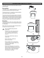
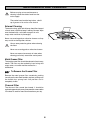
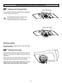
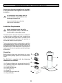
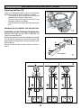
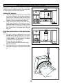
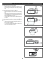
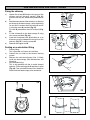
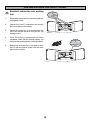
INSTRUCTION BOOKLET
COOKER HOOD
ZHC 916X
Thank you for buying a Zanussi product.
To enable you to use your appliance effectively and safely, please read this instruction book carefully before using
the appliance and retain for future reference. If you require guidance in the use of the appliance or require further
information on Zanussi Products, please contact our Customer Care Department. For general enquiries concerning
your Zanussi appliance or for further information, visit our website at http:\\www.zanussi.co.uk
Customer Care Department
Zanussi
55-77 High Street
Slough
Berkshire
SL1 1DZ
Tel:
Fax:
08705 727727(*)
01753 538972
* calls to this number may be recorded for training purposes.
To register ownership, please ensure you complete and return the guarantee card supplied with the appliance.
For the User
For the Installer
Important Safety Information
Installation Instructions
Technical Information
Your Appliance
Electrical Connections
Electrical Requirements
Electrical Connection
Operating Instructions
Cooker Hood Controls
To Operate
Recirculation
Extraction
Installing the Cooker Hood
Service and Spare Parts
Installation Requirements
Unpacking
Clearance Height
Selecting the Type of Installation
Fixing the Chimney to the Canopy
Fitting the Hood to the Wall
Drilling the Shelves
Bottom Shelf
Top Shelf
Installation in Recirculation Mode
Installation with Air Outlet Turned to the Wall
Installation with Air Outlet Turned Left or Right
Final Fixing and Adjustment of Hood
Ducting
Recirculation
Guarantee Conditions
Electrical Connection and Working Test
Maintenance and Cleaning
External Cleaning
Metal Grease Filter
To Remove the Grease Filter Cassette
Charcoal Filter
To Remove/Replace the Charcoal Filter
Worktop Lighting
Replacing the Light Bulb
Something Not Working
Guide to use the instruction book
The following Symbols will be found in the text to guide you through the instruction book
Safety instructions
Step by step instructions
2
IMPORTANT SAFETY INFORMATION
These warnings are provided in the interests of your safety. Ensure that you understand them all before
installing or using this appliance. Your safety is of paramount importance. If you are unsure about any of
the meanings of these warnings contact the Customer Care Department.
Installation
•
Child Safety
Any installation work must be undertaken by a
qualified electrician or a competent person.
•
This hood must be installed in accordance with the
installation instructions and all measurements must
be adhered to.
•
If the cooker hood is installed for use above a gas
appliance then the provision for ventilation must be
in accordance with the Gas Safety Codes of Practice
BS.6172, BS.5440 and BS.6891 (Natural Gas) and
BS.5482 (LP Gas) 1994, the Gas Safety (Installation
& Use) Regulations, the Building Regulations issued
by the Department of the Environment, the Building
standards (Scotland) (Consolidated) Regulations
issued by the Scottish Development Department.
•
This appliance is designed to be operated by adults.
Children should not be allowed to tamper with the
controls or play with the appliance.
During Use
•
The fan motor of this cooker hood incorporates a cutout device which will operate if the cooker hood is
installed below the minimum height recommended
under section ‘Clearance Height’, or if the motor
becomes overheated. If the cut-out device is
activated, switch off the fan motor and allow the
cooker hood to cool. The cut-out device will reset
itself when the fan motor has cooled significantly.
•
It is dangerous to alter the specifications or modify
this product in any way.
•
When installed between adjoining wall cabinets the
wall cabinets must not overhang the hob.
•
If the room where the hood is to be used contains a
fuel burning appliance such as a central heating boiler
then its flue must be of the room sealed or balanced
flue type.
•
If other types of flue or appliances are fitted ensure
that there is an adequate supply of air to the room.
•
The ducting system for this appliance must not be
connected to any existing ventilation system which
is being used for any other purpose.
•
Do not install above a cooker with a high level grill.
•
This product is for domestic use only.
•
Never leave frying pans unattended during use as
over-heated fats and oils might catch fire.
•
Never do flambé cooking under this cooker hood.
•
Do not leave naked flames under the hood.
Maintenance and Service
3
•
This appliance can be a hazard if the synthetic paper
and charcoal filters are not replaced as
recommended.
•
Under no circumstances should you attempt to repair
the appliance yourself. Repairs carried out by
inexperienced persons may cause injury or more
serious malfunction. Refer to your local Zanussi
Service Force Centre. Always insist on genuine spare
parts.
YOUR APPLIANCE
OPERATING INSTRUCTIONS
This cooker hood is designed to extract unpleasant
odours from the kitchen, it will not extract steam.
To obtain the best performance it is advisable to switch
on the hood a few minutes before you start cooking and
leave it running for approximately 15 minutes after
finishing.
Cooker Hood Controls
V1.
V2.
V3.
L.
Push to engage the low speed, for use with one
burner or simmering.
Push to engage the medium speed, for normal
cooking up to four pans.
Push to engage the high speed, for use when
frying or cooking foods with strong odours.
Push to switch on the worktop illumination lamps.
4
OPERATING INSTRUCTIONS
This cooker hood can be used to recirculate or extract
contaminated air.
Recirculation
The cooker hood is supplied specified for use in the
recirculation mode with the charcoal filter fitted.
The contaminated air is cleaned by passing through the
filters and then back into the kitchen.
S07_29
The activated charcoal filter absorbs odours arising from
cooking. In use it will slowly become saturated in grease
and less effective. The filter normally requires changing
after at least every three months or more frequently if
the hood is used for more than three hours per day.
Extraction
The contamined air enters the cooker hood passing
through the grease filter and out through the ducting into
the atmosphere.
When used in the extraction mode the charcoal filter is
not required and must be removed.
Never do flambé cooking under this
cooker hood.
Take extra care when frying and never
leave frying pans unattended during
use, as over-heated fats and oils can
catch fire.
R
Do not leave naked flames under the
cooker hood.
Ensure the hood is switched on
before using the hob.
Ensure heating areas on your hob are
covered with pots and pans when using
the hob and cooker hood
simultaneously.
W
S07_30
Ensure not to damage the charcoal filter
when cleaning or replacing as the activated
charcoal inside is saturated with grease,
which will stain if it comes into contact
with clothing or furnishings.
5
R
W
MAINTENANCE AND CLEANING
Before carrying out any maintenance or
cleaning isolate the cooker hood from the
mains supply.
The cooker hood must be kept clean, a build
up of grease or fat can be a fire hazard.
External Cleaning
S07_06
The metal casing, grille and chimney should be cleaned
at least once a month to keep it looking like new. Wipe
over the hood with a soft cloth wrung out in mild
soapy water and than dry thoroughly.
Never use scouring pads or abrasive cleaners as they
may scratch or damage the surfaces.
Always wear protective gloves when cleaning
the hood.
Never use scouring pads or abrasive cleaners.
Never use excessive amounts of water when
cleaning particularly around the control panel.
Metal Grease Filter
The metal grease filter should be cleaned at least every
month. The filter may be washed by hand using mild
soapy water, or can be machine washed in a
dishwasher.
To Remove the Grease Filter
Remove the metal grease filter cassette by pushing
inwardly on the two steel handles; replace, making sure
the handle has sprung back into position and is
completely visible.
Charcoal Filter
The charcoal filter cannot be cleaned, it should be
replaced approximately every three months or more often
if the hood is used for more than three hours per day.
6
MAINTENANCE AND CLEANING
To Remove the Charcoal Filter
Push inwardly on the two retaining clips to disengage
the security fixing and remove.
S07_2
This appliance can be a fire hazard if the
grease and charcoal filters are not
cleaned and replaced as recommended.
S07_3
Worktop Lighting
The lamps should be replaced with a 220-240V 20W
halogen spot lamp.
To Remove the Lamps
Unscrew the two screws to release the metal surround.
Remove a lamp from the holder by pulling the lamp
downwards.
S07_28
When fitting the new lamp ensure the two pins are
correctly inserted into the slots in the lamp holder.
Charcoal filters, grease filters and lamps can be
obtained from your local Service Force Centre.
7
SOMETHING NOT WORKING
If, having followed these instructions carefully, your cooker hood fails to work properly please carry out
the following checks.
Solution
Symptom
The cooker hood will not start
• Check the hood is connected to the electricity supply.
• Check that the fan speed control is set to 1, 2 or 3.
The cooker hood is not working effectively
• The fan speed is set high enough for the task.
• The grease filter is clean.
• The kitchen is adequately vented to allow the entry
of fresh air.
• If set up for recirculation, check that the charcoal
filter is still effective.
• If set up for extraction, check that the ducting and
outlets are not blocked.
The cooker hood has switched off during
operation
• The safety cut-out device has been tripped.
• Turn off the hob and then wait for the device to reset.
If after all these checks, the problem persists,
contact your local Service Force Centre,
quoting the model and serial number.
In-guarantee customers should ensure
that the above checks have been made as
the engineer will make a charge if the fault
is not a mechanical or electrical
breakdown.
Please note that it will be necessary to
provide proof of purchase for any
in-guarantee service calls.
SERVICE AND SPARE PARTS
If you require an engineer or wish to purchase spare
parts contact your local Service Force Centre by
telephoning:
For general assistance with your appliance or for
information on Zanussi products please contact our
Customer Care Department.
Customer Care Department,
Zanussi
55-77 High Street
Slough
Berkshire
SL1 1DZ
08705 929929
Your telephone call will be routed to your local
Service Force Centre. The addresses are listed at the
back of the book.
Tel: 08705 727 727(*)
*calls to this number may be recorded for training
purposes.
8
PEACE OF MIND FOR TWENTY FOUR MONTHS
STANDARD GUARANTEE CONDITIONS
We, Zanussi, undertake that if within twenty four months of the date of the purchase this Zanussi built-in appliance
or any part there of is proved to be defective by reason only of faulty workmanship or materials, the company will, at
our option repair or replace the same FREE OF ANY CHARGE for labour, materials or carriage on condition that:
•
•
•
•
•
The appliance has been correctly installed and used only on the electrical supply stated on the rating plate.
The appliance has been used for normal domestic purposes only, and in accordance with the manufacturer’s
operating and maintenance instructions.
The appliance has not been serviced, maintained, repaired, taken apart or tampered with by any person not
authorised by us.
All service work under this guarantee must be undertaken by Zanussi Service Force Centre.
Any appliance or defective part replaced shall become the property of this company.
Home visits are made between 8.30am and 5.30pm Monday to Friday. Visits may be available outside these hours
in which case a premium will be charged.
EXCLUSIONS
This Guarantee does not cover:
Damage or calls resulting from transportation, improper use or neglect, the replacement of any lilght bulbs or removable
parts of glass or plastic.
• Costs incurred for calls to put right appliances improperly installed or calls to appliances outside the United
Kingdom.
• Appliances found to be in use within a commercial environment, plus those which are the subject of rental
agreements.
• Products of Zanussi manufacture which are not marked by Zanussi.
This guarantee is in addition to your statutory and legal rights.
ZANUSSI EUROPEAN GUARANTEE
If you should move to another country within Europe then your guarantee moves with you to your new home subject
to the following qualifications:
• The guarantee starts from the date you first purchased your product.
• The guarantee is for the same period and to the same extent for labour and parts as exists in the new country of
use for this brand or range of products.
• This guarantee relates to you and cannot be transferred to another user.
• Your new home is within the European Community (EC) or European Free Trade Area.
• The product is installed and used in accordance with our instructions and is only used domestically, i.e. a normal
household.
Before you move please contact your nearest Customer Care Centre, listed below, to give them details of
your new home. They will then ensure that the local Service Organisation is aware of your move and able to
look after you and your appliances.
France
Germany
Italy
Sweden
UK
Senlis
Nurnberg
Pordenone
Stockholm
Slough
+33 (0)3 44 62 29 99
+49 (0)911 323 2600
+39 (0)1678 47053
+46 (0)8 738 79 50
+44 (0)1753 219 897
9
INSTALLATION INSTRUCTIONS
It is dangerous to alter the specifications or attempt to modify this product in any way.
Technical Information
DIMENSIONS
HEIGHT (CANOPY):
HEIGHT (CHIMNEY):
WIDTH (CANOPY):
WIDTH (CHIMNEY):
GROSS:
NET:
ELECTRICAL SUPPLY:
POWER CONSUMPTION:
FAN MOTOR:
LAMP:
(2x20W) HALOGEN Ø 35 mm GUA
SUITABLE FOR INSTALLATION
ABOVE:
73 mm
450-850 mm
898 mm
Ø200-Ø270 mm
24.00 kg
19,40 kg
220-240 V (50 Hz)
215 W
175 W
40 W
ELECTRIC HOB:
GAS HOB:
SLOT-IN GAS COOKER
SLOT-IN ELECTRIC COOKER
7 KW
10 KW
13.5 KW
12.4 KW
Note: CE Marking certifies that this appliance complies with the requirements
laid down in EEC directive 89:336. (Electromagnetic compatibility) and
subsequent modifications and Low Voltage directive 72/23/E.
ELECTRICAL CONNECTIONS
This appliance must be earthed
Electrical Requirements
This appliance is fitted with a 3 core mains
cable and must be permanently connected to
the electricity supply via a double-pole switch
having 3mm minimum contact gap on each
pole. A Switched Fuse Connection Unit to
BS1363 Part 4, fitted with a 3 Amp fuse, is a
recommended mains supply connection
accessory to ensure compliance with the Safety
Requirements applicable to fixed wiring
instructions.
Any permanent electrical installation must
comply with the latest I.E.E. Regulations and
local Electricity Board regulations. For your own
safety this should be undertaken by a qualified
electrician e.g. your local Electricity Board, or a
contractor who is on the roll of the National
Inspection Council for Electrical Installation
Contracting (NICEIC).
Electrical Connection
Before connecting to the mains supply ensure
that the mains voltage corresponds to the
voltage on the rating plate inside the cooker
hood.
This appliance conforms to BS 800: 1988 and
EEC Directive No. 78 308 regarding
suppression of radio and television
interference.
10
INSTALLING THE COOKER HOOD
Please ensure that when the appliance is installed it
is easily accessible to an engineer in the event of a
breakdown.
All installations must comply with the
local authorities requirements for the
discharge of exhaust air.
Incorrect installation may affect the
safety of this cooker hood.
Installation Requirements
Before installation check the wall to
which the cooker hood is to be fitted for
electric cables, water pipes or gas.
The cooker hood is designed to be fixed to a solid block
or brick wall over a cooking area. If not, suitable fixings
must be used for other types of walls. The hood can be
used in the extraction (ducted to the outside) or
recirculation (internal recycling) mode.
The Installation work must be undertaken by a qualified
and competent person. The manufacturer disclaims any
responsibility to damages due to incorrect installation of
the cooker hood or if the cooker hood is not installed in
compliance with relevant regulations controlling this type
of installation.
Unpacking
Before unpacking the cooker hood position the carton
with the arrows pointing upwards as illustrated on the
carton.
The ZHC916 is supplied with the following
components for installation:
1 No.
1 No.
1 No.
1 No.
1 No.
1 No.
1 No.
1 No.
Canopy including controls and worktop illumination (C).
Telescopic chimney stack complete with fan motor (A).
Flange 120mm (F).
Collar 120-125mm (D)
Venting grille (G).
Spigot (R).
Ducting conversion bend (W)
Support Rod (B)
S
F
G
R
W
11
INSTALLING THE COOKER HOOD
Clearance Heights
The cooker hood is designed to be fitted over a cooking
appliance at the clearance heights stated, provided the
maximum output of the appliance beneath does not
exceed the maximums quoted in the Technical
Specifications.
If the output of the appliance below the cooker hood
exceeds the maximum outputs quoted, please refer to
the cooker manufacturer’s installation instructions.
Hob
A clearance height of 650mm (25 1/2 ins) is required
when installed above a built-in electric hob, or 700mm
(27 1/2 ins) when installed above a built-in gas hob.
A: Built-in Electric Hob:
B: Built-in Gas hob:
C: Slot-in Electric Cooker:
D: Slot-in Gas Cooker:
650mm clearance
700mm clearance
685mm clearance
787mm clearance
A clearance height of 685mm (27 ins) is required when
installed above a slot-in electric oven, or 787mm (30 1/
2 ins) when installed above a slot-in gas oven.
When installed between adjoining wall cabinets, the wall
cabinets must not overhang the hob and the distance
beetween the underside of the cabinet and the worktop
must be 450mm. If the height of the wall cabinet is less
than 450mm a gap of 50mm must be maintained
either side of the hob.
This cooker hood must not be installed
above a cooking appliance with a high
level grill.
3
Selecting the type of installation:
R
The extraction unit at the top of the chimney can be
installed in one of three ways.
Air outlet turned upwards recirculation only (fig.
2a).
2.
Air outlet turned towards the wall -extraction only
(fig. 3).
3.
Air outlet turned left or right -extraction only (fig.
4a and 4b).
4b
W
S07_30
1.
W
12
R
4a
INSTALLATION INSTRUCTIONS
Draw a vertical line on the wall from the centre of the
cooking appliance, using a spirit level and marking pen.
This is to ensure the correct level of alignment of the
appliance (5).
Mark the hole position (1) on the wall 100mm either side
of the vertical line ensuring that they are level and that
the distance between the lowest point of the hood and
the cooking appliance beneath meet the clearance
requirements quoted in the paragraph titled ‘Clearance
Heights’ (* - Page 12).
48
1
1
ø8
*
100 100
20
5
Using an 8mm masonry bit, drill the holes for the canopy
and insert a suitable wall fixing plug ready for the fixing
screws.
Fix the round eyelet screws provided tightly into the holes
(Fig.6).
Fitting the hood canopy
Remove the metal grease filter and the activated
charcoal filter, if there are any (see Maintenance &
Cleaning).
Fit the support rod B using the two screws K (3.5 x 9.5)
provided.
Hook the hood canopy C to the eyebolts O fixed in hole
(1). Adjust the support rod B so that it pushes against
the wall, keeping the canopy horizontal.
The support rod must be correctly fixed and adjusted.
It must not be removed until the installation has been
completed and checked.
Failure to ensure correct fixing could cause the canopy
fixing hooks and eyelet bolts to be damaged or distorted.
This may compromise the safety of the installation.
6
Not supplied
1
O
8
O
O
_09
S07
7
B
O
K
A08_08
A08_10
B
9
13
INSTALLATION INSTRUCTIONS
Adjusting Position (10)
There are 2 adjustable hooks at the rear of the hood,
which can be used to adjust its position as follows:
Turn screws L until the position of screws N
coincides with the lower access holes.
Turn the screws N to adjust the vertical and
horizontal position of the hood.
Lock the screws L to fasten the hood against the
wall.
N
L
T
N L
A08_11
WARNING! DO NOT REMOVE THE SUPPORT ROD
L
T
N
10
Installation of the Chimney fixing bracket
Determine the height that the motor will be fitted and
also the air outlet direction.
When these positions have been decided fix bracket S
(11) to the wall referring to relevant illustration (12)
regarding the direction of the air outlet and where to fix
the bracket (2).
Ensure that the bracket is fixed exactly as shown in
FIG. 11
2
S
A08_07
Not
supplied
V
L=
44
mm
Not supplied
11
12
2
2
105
2
1
100 100
ø8
650
48
1
20
X
Z
7
50
ø1
2
0
ø1
105
S07_05
14
1
1
1
1
INSTALLATION INSTRUCTIONS
Regardless of which type of installation, any wooden
shelves in the area where the hood is to be fitted must
first be removed, drilled and later replaced.
13
Drilling the shelves
b)
Using the template provided, and taking hole B
as a point of reference, drill the shelves along the
central axis to allow the passage of the chimney.
The chimney must be inserted into the shelves
before it is fixed to the hood canopy (Fig. 13).
When installing the ducting version with the air
outlet directed upwards, if the ducting fan unit is
positioned below the line of the shelves it will be
necessary to drill a suitable hole in the top shelf
only, to allow the air ducting pipe to pass through
(Fig. 14).
S07_08
a)
14
Direction and position of the ducting fan
unit
The hood is normally supplied with the air outlet
directed towards the wall (Fig. 3), if it is to be
installed with the air outlet directed to the right or
left (Fig. 4a-4b), it will be necessary to change
the direction of the ducting fan unit.
- Unscrew the screws U (Fig. 15).
- Turn the ducting fan unit 60° to the left or right.
- Replace the screws.
b)
The ducting fan unit air outlets must be arranged
according to the type of installation to be carried
out.
S07_09
a)
15
U
U
A08_14
15
INSTALLATION INSTRUCTIONS
Air outlet directed upwards (Fig. 2a-b):
- Remove the plastic plug from the upper part of
the venting grill and replace it on the rear part (Fig.
16).
16
Air outlet directed towards the wall (Fig. 3):
- Remove the plastic frame from the air outlet (Fig.
17).
- Remove the plug from the upper part of the ducting
fan unit (Fig. 18), as it is not possible to insert the
flange F with the plug in place.
- Fit the flange F Ø 120 or 150 mm (Fig. 19), replace
the plug.
17
Air outlet directed to the left or right hand side (Fig. 4ab):
- Remove the four screws fastening the plastic frame, as shown in Fig. 17.
- Fit the ducting spigot R (Fig. 20) and replace the
four screws removed as above.
18
19
20
16
INSTALLATION INSTRUCTIONS
Fixing the chimney
a)
b)
c)
d)
e)
21
I
Loosen the screws M fixing the two parts of the
chimney and pull the inner section I (Fig. 21)
almost all the way out. Remove the protective film
P.
Rest the lower section of the chimney in its housing
on the top of the hood canopy. Lower the ducting
fan unit until it reaches the wall bracket S and fix
it using the screw H provided (Fig. 22).
Fit cover D provided on the wall bracket S (Fig.
23).
Fix the chimney A to the hood canopy C using
four screws provided (Fig. 24).
Insert the transparent seal Q provided, so as to
eliminate any play between the two parts of the
chimney (Fig. 25). Lock the screws M.
Remove the support rod B.
P
M
A08_20
22
S
H
S
Ducting or re-circulation fitting
1.
a)
b)
2.
Ducting fitting:
This is possible in all forms of installation.
Connect the air outlet to the external ducting
system.
Remove the activated charcoal filter (if fitted)
inside the hood canopy (See Maintenance and
Cleaning).
Re-circulation fitting:
This is only possible with the air outlet directed
upwards. Fit the venting grille G onto the air outlet
(Fig. 26). The activated charcoal filter should be
fitted inside the hood canopy after connection.
A08_21
D
23
A08_22
E
E
E
26
B
E
24
25
Q
Q
A08_24
17
INSTALLATION INSTRUCTIONS
Electrical connection and working
test:
1.
Remove the metal cover by unscrewing the four
self tapping screws.
2.
Connect the ‘Push-Fit’ connectors coming from
the fan assembly to the canopy.
3.
Position the terminals as illustrated under the
cover and replace the cover with the four self
tapping screws.
4.
Once the electrical connection has been
completed, check that the worktop lighting, fan
motor and the speed selection is working properly.
5.
Replace the charcoal filter (if the hood is to be
used in the recirculation mode) and the metal
grease filter cassette.
S07_24
S07_34
18
Service and Spare Parts
In the event of your appliance requiring service, or if you wish
to purchase spare parts please contact your local Service
Force Centre by telephoning:
08705 929929
Your telephone call will be automatically routed to the Service
Force centre covering your post code area.
For the address of your local Service Force Centre and further
information about Service Force, please visit the website at
www.serviceforce.co.uk
Before calling out an engineer, please ensure you read the
details under the heading Something not working.
When you contact the Service Force Centre you will need to
give the following details:
1. Your name, address and post code
2. Your telephone number
3. Clear and concise details of the fault
4. The model and serial number (found on the rating plate)
5. The purchase date
Please note that a valid purchase receipt or guarantee
documentation is required for in-guarantee service calls.
For Customer Service in Ireland please contact us at the
address below:
Zanussi
Electrolux Group (Irl) Ltd
Long Mile Road
Dublin 12
Republic of Ireland
Tel: + 353 (0)1 4090751
Email: [email protected]
Customer Care
Department
For general enquiries concerning your Zanussi appliance or for
further information on Zanussi products please contact our
Customer Care Department by letter or telephone at the
address below or visit our website at www.zanussi.co.uk
Customer Care Department
Zanussi
55-77 High Street
Slough
Berkshire
SL1 1DZ
Tel: 08705 727727 (*)
* calls to this number may be recorded for training purposes
19
© Electrolux plc 2002
4329161_12 - 041207