1
INVERTER
M4000
M4000
INSTRUCTION MANUAL
OUTLINE Chapter 1
INVERTER
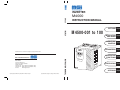
M 4500-001 to 100
INSTALLATION
AND WIRING Chapter 2
OPERATION/
CONTROL Chapter 3
PARAMETERS Chapter 4
Specifications an contents are subject to change without notice.
PROTECTIVE Chapter 5
FUNCTIONS
MGI T ECHNOLOGIES INC.
275 West 4th Avenue
Vancouver, British Columbia
Canada V7N 3B1
Toll Free Tell: (877) 539-2542 (Canada & USA)
Toll Free Fax: (800) 539-2542 (Canada & USA)
Internet:
www.mgitech.com
IB (NA) 0600194ENG-A (0404) MEE Printed in Japan
Specifications subject to change without notice.
INSTRUCTION MANUAL
Head Office:
SPECIFICATIONS Chapter 6
OPTIONS Chapter 7
Thank you for choosing this MGI Inverter.
This instruction manual gives handling information and precautions for use of this
equipment.
Incorrect handling might cause an unexpected fault. Before using the inverter, please read
this manual carefully to use the equipment to its optimum.
Please forward this manual to the end user.
This section is specifically about safety matters
Do not attempt to install, operate, maintain or inspect the inverter until you have read through this
instruction manual and appended documents carefully and can use the equipment correctly.
Do not use the inverter until you have a full knowledge of the equipment, safety information and
instructions.
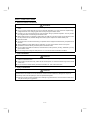
In this instruction manual, the safety instruction levels are classified into “WARNING” and “CAUTION”.
WARNING
Assumes that incorrect handling may cause hazardous conditions, resulting in
death or severe injury.
CAUTION
Assumes that incorrect handling may cause hazardous conditions, resulting in
medium or slight injury, or may cause physical damage only.
Note that the CAUTION level may lead to a serious consequence according to conditions. Please follow
the instructions of both levels because they are important to personnel safety.
A-1
SAFETY INSTRUCTIONS
1. Electric Shock Prevention
WARNING
z While power is on or when the inverter is running, do not open the front cover. You may get an electric
z
z
z
z
z
z
z
z
z
shock.
Do not run the inverter with the front cover removed. Otherwise, you may access the exposed highvoltage terminals or the charging part of the circuitry and get an electric shock.
If power is off, do not remove the front cover except for wiring or periodic inspection. You may access
the charged inverter circuits and get an electric shock.
Before starting wiring or inspection, switch power off, wait for more than at least 10 minutes and check
for the presence of any residual voltage with a meter (check chapter 2 for further details.) etc.
Earth the inverter.
Any person who is involved in the wiring or inspection of this equipment should be fully competent to do
the work.
Always install the inverter before wiring. Otherwise, you may get an electric shock or be injured.
Operate the switches with dry hands to prevent an electric shock.
Do not subject the cables to scratches, excessive stress, heavy loads or pinching. Otherwise, you may
get an electric shock.
Do not change the cooling fan while power is on. To do so will invite a hazardous condition.
2. Fire Prevention
CAUTION
z Mount the inverter on an incombustible surface. Installing the inverter directly on or near a combustible
surface could lead to a fire.
z If the inverter has become faulty, switch off the inverter power. A continuous flow of large current could
cause a fire.
z Do not connect a resistor directly to the DC terminals P, N. This could cause a fire.
3. Injury Prevention
CAUTION
z
z
z
z
Apply only the voltage specified in the instruction manual to each terminal to prevent damage etc.
Ensure that the cables are connected to the correct terminals. Otherwise, damage etc. may occur.
Always make sure that polarity is correct to prevent damage etc.
After the inverter has been operating for a relatively long period of time, do not touch the inverter as it
may be hot and you may get burnt.
A-2
4. Additional instructions
Also note the following points to prevent an accidental failure, injury, electric shock, etc.:
(1) Transportation and installation
CAUTION
z When carrying products, use correct lifting gear to prevent injury.
z Do not stack the inverter boxes higher than the number recommended.
z Ensure that installation position and material can withstand the weight of the inverter. Install
z
z
z
z
z
z
z
according to the information in the Instruction Manual.
Do not operate if the inverter is damaged or has parts missing.
Do not hold the inverter by the front cover; it may fall off.
Do not stand or rest heavy objects on the inverter.
Check the inverter mounting orientation is correct.
Prevent screws, wire fragments, conductive bodies, oil or other flammable substances from entering
the inverter.
Do not drop the inverter, or subject it to impact.
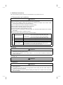
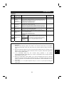
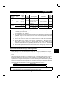
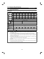
Use the inverter under the following environmental conditions:
Environment
Constant torque: -10°C to +40°C (14°F to 104°F) (non-freezing)
(-10°C to +30°C with FR-A5CV
attachment)
Ambient temperature
Variable torque: -10°C to +40°C (14°F to 104°F) (non-freezing)
(-10°C to +30°C with FR-A5CV
attachment)
Ambient humidity
90%RH or less (non-condensing)
Storage temperature -20°C to +65°C* (-4°F to 149°F)
Ambience
Indoors (free from corrosive gas, flammable gas, oil mist, dust and dirt)
Maximum 1000m (3280.80 feet.) above sea level for standard operation.
Altitude, vibration
After that derate by 3% for every extra 500m up to 2500m (91%).
2
5.9 m/s {0.6G} or less (conforming to JIS C0911)
*Temperatures applicable for a short time, e.g. in transit.
(2) Wiring
CAUTION
z Do not fit capacitive equipment such as a power factor correction capacitor, radio noise filter or surge
suppressor to the output of the inverter.
z The connection orientation of the output cables U, V, W to the motor will affect the direction of
rotation of the motor.
(3) Trial run
CAUTION
z Check all parameters, and ensure that the machine will not be damaged by a sudden start-up.
(4) Operation
CAUTION
z When you have chosen the retry function, stay away from the equipment as it will restart suddenly
after an alarm stop.
z The [STOP] key is valid only when the appropriate function setting has been made. Prepare an
emergency stop switch separately.
z Make sure that the start signal is off before resetting the inverter alarm. A failure to do so may restart
the motor suddenly.
A-3
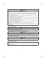
CAUTION
z The load used should be a three-phase induction motor only. Connection of any other electrical
equipment to the inverter output may damage the equipment.
z The electronic over current protection does not guarantee protection of the motor from overheating.
z Do not use a magnetic contactor on the inverter input for frequent starting/stopping of the inverter.
z Use a noise filter to reduce the effect of electromagnetic interference. Otherwise nearby electronic
z
z
z
z
z
z
equipment may be affected.
Take measures to suppress harmonics. Otherwise power harmonics from the inverter may
heat/damage the power capacitor and generator.
When a 575V class motor is inverter-driven, it should be insulation-enhanced or surge voltages
suppressed. Surge voltages attributable to the wiring constants may occur at the motor terminals,
deteriorating the insulation of the motor.
When parameter clear or all clear is performed, each parameter returns to the factory setting. Re-set
the required parameters before starting operation.
The inverter can be easily set for high-speed operation. Before changing its setting, examine the
performance of the motor and machine.
In addition to the inverter's holding function, install a holding device to ensure safety.
Before running an inverter which had been stored for a long period, always perform inspection and
test operation.
(5) Emergency stop
CAUTION
z Provide a safety backup such as an emergency brake which will prevent the machine and equipment
from hazardous conditions if the inverter fails.
(6) Maintenance, inspection and parts replacement
CAUTION
z Do not carry out a megger (insulation resistance) test on the control circuit of the inverter.
(7) Disposing of the inverter
CAUTION
z Treat as industrial waste.
(8) General instructions
Many of the diagrams and drawings in this instruction manual show the inverter without a cover, or partially
open. Never run the inverter like this. Always replace the cover and follow this instruction manual when
operating the inverter.
A-4
1 OUTLINE
1
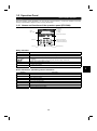
1.1 Pre-Operation Information .........................................................................................................................................1
1.1.1 Precautions for operation...................................................................................................................................1
1.2 Basic Configuration....................................................................................................................................................2
1.2.1 Basic configuration.............................................................................................................................................2
1.3 Structure ....................................................................................................................................................................3
1.3.1 Appearance and structure..................................................................................................................................3
1.3.2 Removal and reinstallation of the front cover.....................................................................................................4
1.3.3 Removal and reinstallation of the operation panel.............................................................................................6
2 INSTALLATION AND WIRING
7
2.1 Installation..................................................................................................................................................................7
2.1.1 Instructions for installation .................................................................................................................................7
2.2 Wiring ......................................................................................................................................................................10
2.2.1 Terminal connection diagram...........................................................................................................................10
2.2.2 Wiring of the main circuit .................................................................................................................................13
2.2.3 Wiring of the control circuit ..............................................................................................................................18
2.2.4 Connection to the PU connector ......................................................................................................................22
2.2.5 Connection of brake resistor and DC reactor...................................................................................................24
2.2.6 Design information ...........................................................................................................................................26
2.3 Other wiring .............................................................................................................................................................27
2.3.1 Inverter-generated noises and reduction techniques.......................................................................................27
2.3.2 Leakage currents and countermeasures .........................................................................................................30
2.3.3 Inverter-driven 575V class motor .....................................................................................................................31
2.3.4 Peripheral devices ...........................................................................................................................................32
2.3.5 Additional guidelines for compliance with UL and CSA standards ..................................................................34
3 OPERATION/CONTROL
35
3.1 Pre-Operation Information .......................................................................................................................................35
3.1.1 Devices and parts to be prepared for operation...............................................................................................35
3.1.2 Power on 37
3.2 Operation Panel.......................................................................................................................................................38
3.2.1 Names and functions of the operation panel (FR-DU04).................................................................................38
3.2.2 Monitor display changed by pressing the [MODE] key ....................................................................................39
3.2.3 Monitoring mode ..............................................................................................................................................39
3.2.4 Frequency setting mode ..................................................................................................................................39
3.2.5 Parameter setting mode...................................................................................................................................40
3.2.6 Operation mode ...............................................................................................................................................40
3.2.7 Help mode........................................................................................................................................................41
3.2.8 Copy mode.......................................................................................................................................................43
3.3 Operation .................................................................................................................................................................44
3.3.1 Pre-operation checks .......................................................................................................................................44
3.3.2 External operation mode (Operation using external input signals) ..................................................................45
3.3.3 PU operation mode (Operation using the operation panel (FR-DU04)) ..........................................................46
3.3.4 Combined operation mode (Operation using the external input signals and PU) ...........................................47
I
Contents
CONTENTS
4 PARAMETERS
48
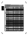
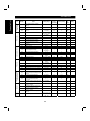
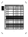
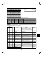
4.1 Parameter List .........................................................................................................................................................48
4.1.1 Parameter list...................................................................................................................................................48
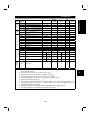
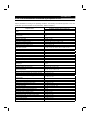
4.1.2 List of Parameters Classified by Purposes of Use...........................................................................................54
4.1.3 Parameter recommended to be set by the user...............................................................................................55
4.2 Parameter Function Details .....................................................................................................................................56
z Torque boost (Pr. 0, Pr. 46, Pr. 112) .......................................................................................................................56
z Output frequency range (Pr. 1, Pr. 2, Pr. 18) ..........................................................................................................57
z Base frequency, base frequency voltage (Pr. 3, Pr. 19, Pr. 47, Pr. 113).................................................................58
z Multi-speed operation (Pr. 4 to Pr. 6, Pr. 24 to Pr. 27, Pr. 232 to Pr. 239) ..............................................................59
z Acceleration/deceleration time (Pr. 7, Pr. 8, Pr. 20, Pr. 21, Pr. 44, Pr. 45, Pr. 110, Pr. 111) ..................................60
z Electronic overcurrent protection (Pr. 9)..................................................................................................................61
z DC dynamic brake (Pr. 10, Pr. 11, Pr. 12)...............................................................................................................62
z Starting frequency (Pr. 13) ......................................................................................................................................63
z Load pattern selection (Pr. 14) ................................................................................................................................64
z Jog operation (Pr. 15, Pr. 16) ..................................................................................................................................65
z MRS input selection (Pr. 17) ...................................................................................................................................66
z Stall prevention (Pr. 22, Pr. 23, Pr. 66, Pr. 148, Pr. 149, Pr. 154)...........................................................................67
z Multi-speed input compensation (Pr. 28).................................................................................................................68
z Acceleration/deceleration pattern (Pr. 29, Pr. 140 to Pr. 143).................................................................................69
z Regenerative brake duty (Pr. 30, Pr. 70).................................................................................................................70
z Frequency jump (Pr. 31 to Pr. 36) ...........................................................................................................................71
z Speed display (Pr. 37, Pr. 144) ...............................................................................................................................72
z Up-to-frequency sensitivity (Pr. 41) .........................................................................................................................73
z Output frequency detection (Pr. 42, Pr. 43, Pr. 50, Pr. 116) ...................................................................................73
z Second/third stall prevention (Pr. 48, Pr. 49, Pr. 114, Pr. 115) ...............................................................................74
z Monitor display/FM, AM terminal function selection (Pr. 52 to Pr. 54, Pr. 158) .......................................................76
z Monitoring reference (Pr. 55, Pr. 56).......................................................................................................................78
z Automatic restart after instantaneous power failure (Pr. 57, Pr. 58, Pr. 162 to Pr. 165) .........................................79
z Remote setting function selection (Pr. 59) ..............................................................................................................81
z Intelligent mode selection (Pr. 60)...........................................................................................................................82
z Acceleration/deceleration reference current/lift mode starting frequency (Pr. 61 to Pr. 64)....................................84
z Retry function (Pr. 65, Pr. 67 to Pr. 69) ...................................................................................................................85
z Applied motor (Pr. 71) .............................................................................................................................................87
z PWM carrier frequency (Pr. 72, Pr. 240) .................................................................................................................88
z Voltage input (Pr. 73) ..............................................................................................................................................89
z Input filter time constant (Pr. 74) .............................................................................................................................90
z Reset selection/PU disconnection detection/PU stop selection (Pr. 75) .................................................................90
z Alarm code output selection (Pr. 76) .......................................................................................................................92
z Parameter write inhibit selection (Pr. 77) ................................................................................................................93
z Reverse rotation prevention selection (Pr. 78) ........................................................................................................94
z Operation mode selection (Pr. 79) ..........................................................................................................................95
z Motor capacity/number of motor poles/speed control gain (Pr. 80, Pr. 81, Pr. 89) .................................................98
z Offline auto tuning function (Pr. 82 to Pr. 84, Pr. 90 to Pr. 94, Pr. 96) ..................................................................100
z Online auto tuning selection (Pr. 95) .....................................................................................................................106
z V/F control frequency (voltage) (Pr. 100 to Pr. 109)..............................................................................................108
z Computer link operation (Pr. 117 to Pr. 124).........................................................................................................109
z PID control (Pr. 128 to Pr. 134) .............................................................................................................................119
z Commercial power supply-inverter switch-over function (Pr. 135 to Pr. 139)........................................................126
II
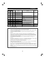
z Output current detection function (Pr. 150, Pr. 151)..............................................................................................130
z Zero current detection (Pr. 152, Pr. 153)...............................................................................................................131
z RT signal activated condition selection (Pr. 155) ..................................................................................................132
z Stall prevention function and current limit function (Pr. 156).................................................................................132
z OL signal output timer (Pr. 157) ............................................................................................................................134
z User group selection (Pr. 160, Pr. 173 to Pr. 176) ................................................................................................135
z Watt-hour meter clear/actual operation hour meter clear (Pr. 170, Pr. 171) .........................................................136
z Input terminal function selection (Pr. 180 to Pr. 186) ............................................................................................136
z Output terminal function selection (Pr. 190 to Pr. 195) .........................................................................................139
z User initial value setting (Pr. 199) .........................................................................................................................141
z Programmed operation function (Pr. 200 to Pr. 231) ............................................................................................142
z Cooling fan operation selection (Pr. 244) ..............................................................................................................146
z Stop selection (Pr. 250).........................................................................................................................................147
z Output phase failure protection selection (Pr. 251) ...............................................................................................148
z Override bias/gain (Pr. 252, Pr. 253).....................................................................................................................148
z Power failure-time deceleration-to-stop function (Pr. 261 to Pr. 266) ...................................................................149
z Stop-on-contact, load torque high-speed frequency selection (Pr. 270) ...............................................................151
z High-speed frequency control (Pr. 271 to Pr. 274)................................................................................................152
z Stop on contact (Pr. 275, Pr. 276).........................................................................................................................156
z Brake sequence function (Pr. 278 to Pr. 285) .......................................................................................................159
z Droop control (Pr. 286, Pr. 287) ............................................................................................................................163
z Meter (frequency meter) calibration (Pr. 900, Pr. 901) ..........................................................................................164
z Frequency setting voltage (current) bias and gain (Pr. 902 to Pr. 905).................................................................166
z Buzzer control (Pr. 990) ........................................................................................................................................171
5 PROTECTIVE FUNCTIONS
172
5.1 Errors (Alarms) ......................................................................................................................................................172
5.1.1 Error (alarm) definitions .................................................................................................................................172
5.1.2 To know the operating status at the occurrence of an alarm .........................................................................181
5.1.3 Correspondences between digital and actual characters ..............................................................................181
5.1.4 Alarm code output..........................................................................................................................................182
5.1.5 Resetting the inverter.....................................................................................................................................182
5.2 Troubleshooting .....................................................................................................................................................183
5.2.1 Motor remains stopped. .................................................................................................................................183
5.2.2 Motor rotates in opposite direction.................................................................................................................183
5.2.3 Speed greatly differs from the setting. ...........................................................................................................183
5.2.4 Acceleration/deceleration is not smooth. .......................................................................................................183
5.2.5 Motor current is large. ....................................................................................................................................184
5.2.6 Speed does not increase. ..............................................................................................................................184
5.2.7 Speed varies during operation. ......................................................................................................................184
5.2.8 Operation mode is not changed properly.......................................................................................................184
5.2.9 Operation panel (FR-DU04) display is not provided. .....................................................................................184
5.2.10 POWER lamp is not lit. ..................................................................................................................................184
5.2.11 Parameter write cannot be performed ...........................................................................................................184
5.3 Precautions for Maintenance and Inspection.........................................................................................................185
5.3.1 Precautions for maintenance and inspection .................................................................................................185
5.3.2 Check items ...................................................................................................................................................185
5.3.3 Periodic inspection.........................................................................................................................................185
5.3.4 Insulation resistance test using megger ........................................................................................................186
5.3.5 Pressure test..................................................................................................................................................186
III
5.3.6 Replacement of parts.....................................................................................................................................189
5.3.7 Inverter replacement ......................................................................................................................................190
5.3.8 Measurement of main circuit voltages, currents and power...........................................................................191
6 SPECIFICATIONS
193
6.1 Standard Specifications .........................................................................................................................................193
6.1.1 Model specifications.......................................................................................................................................193
6.1.2 Common specifications..................................................................................................................................194
6.1.3 Outline drawings ............................................................................................................................................196
7 OPTIONS
200
7.1 Option List..............................................................................................................................................................200
7.1.1 Stand-alone options .......................................................................................................................................200
7.1.2 Inboard dedicated options..............................................................................................................................201
APPENDICES
202
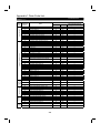
Appendix 1 Data Code List ..........................................................................................................................................202
IV
CHAPTER 1
OUTLINE
This chapter gives information on the basic "outline" of this
product.
Always read the instructions in this chapter before using the
equipment.
1.1 Pre-Operation Information........................................ 1
1.2 Basic Configuration.................................................. 2
1.3 Structure .................................................................. 3
<Abbreviations>
y DU
Operation panel (FR-DU04)
y PU
Operation panel (FR-DU04) and parameter unit (FR-PU04)
y Inverter
MGI inverter M4000 series
y Pr.
Parameter number
y PU operation
Operation using the PU (FR-DU04/FR-PU04)
y External operation
Operation using the control circuit signals
y Combined operation
Operation using both the PU (FR-DU04/FR-PU04) and
external operation
Chapter 1
Chapter 2
Chapter 3
Chapter 4
Chapter 5
Chapter 6
Chapter 7
1
1.1 Pre-Operation Information
OUTLINE
1
OUTLINE
1.1 Pre-Operation Information
1.1.1 Precautions for operation
Incorrect handling might cause the inverter to operate improperly, its life to be reduced considerably, or at the
worst, the inverter to be damaged. Handle the inverter properly in accordance with the information in each
section as well as the precautions and instructions of this manual to use it correctly.
This manual is written for the M4000 series inverters.
For handling information on the parameter unit (FR-PU04), inboard options, stand-alone options, etc., refer to
the corresponding manuals.
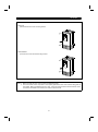
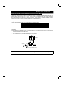
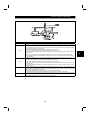
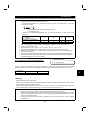
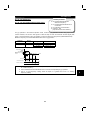
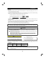
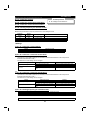
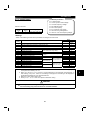
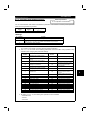
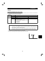
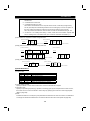
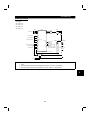
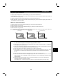
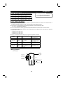
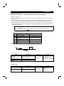
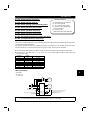
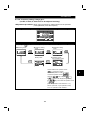
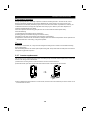
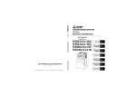
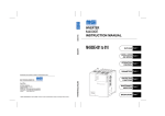
(1) Unpacking and product check
Unpack the inverter and check the capacity plate on the front cover and the rating plate on the inverter side
face to ensure that the product agrees with your order and the inverter is intact.
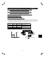
1) Inverter type
Rating plate
MGI Technologies
Capacity plate
INVERTER
MODEL M4500-001
Input rating
M4500-001
Output rating
Serial number
Inverter type
INPUT
Inverter type
: XXXXX
OUTPUT : XXXXX
SERIAL :
MADE IN JAPAN
Rating plate
Capacity plate
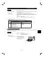
M 4500 - 001
Voltage class
575V class
Symbol
001 to 100
Applicable Motor Capacity
Indicates capacity in "HP".
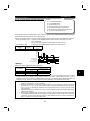
2) Accessory
Instruction manual
If you have found any discrepancy, damage, etc., please contact your sales representative.
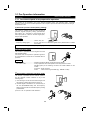
(2) Preparations of instruments and parts required for operation
Instruments and parts to be prepared depend on how the inverter is operated. Prepare equipment and parts
as necessary. (Refer to page 35.)
(3) Installation
To operate the inverter with high performance for a long time, install the inverter in a proper place, in the
correct direction, and with proper clearances. (Refer to page 7.)
(4) Wiring
Connect the power supply, motor and operation signals (control signals) to the terminal block. Note that
incorrect connection may damage the inverter and peripheral devices. (See page 13.)
1
1.2 Basic Configuration
OUTLINE
1.2 Basic Configuration
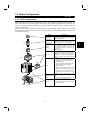
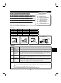
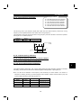
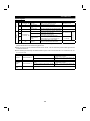
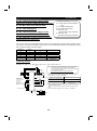
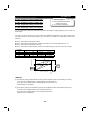
1.2.1 Basic configuration
The following devices are required to operate the inverter. Proper peripheral devices must be selected and
correct connections made to ensure proper operation. Incorrect system configuration and connections can
cause the inverter to operate improperly, its life to be reduced considerably, and in the worst case, the
inverter to be damaged.
Please handle the inverter properly in accordance with the information in each section as well as the
precautions and instructions of this manual. (For connections of the peripheral devices, refer to the
corresponding manuals.)
Name
Power supply
(NFB)
or
(ELB)
Description
Use the power supply within the permissible
power supply specifications of the inverter.
(Refer to page 193.)
Earth leakage
circuit breaker
(ELB) or no-fuse
breaker (NFB)
The breaker should be selected with care
since a large inrush current flows in the
inverter at power on. (Refer to page 32.)
Magnetic
contactor
The magnetic contactor need not be
provided. When installed, do not use it to
start or stop the inverter. It might reduce the
inverter life.
(Refer to page 32.)
(MC)
Reactors
AC reactor
DC reactor
Inverter
The reactors must be used when the power
factor is to be improved or the inverter is
installed near a large power supply system
(1000KVA or more and wiring distance
within 10m (32.81 feet)). Make selection
carefully.
z The inverter life is influenced by ambient
temperature. The ambient temperature
should be as low as possible within the
permissible range.
This must be noted especially when the
inverter is installed in an enclosure.
(Refer to page 7.)
Incorrect wiring might lead to inverter
damage. The control signal lines should
be kept away from the main circuit to
protect them from noise. (Refer to page
10.)
Do not connect a power capacitor, surge
suppressor or radio noise filter to the output
side.
The AC reactor is recommended when the
long distance motor cable is used.
z
Ground
Devices
connected to the
output
Ground
Ground
2
To prevent an electric shock, always ground
the motor and inverter.
1
1.3 Structure
OUTLINE
1.3 Structure
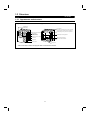
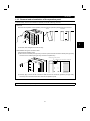
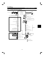
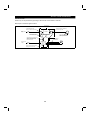
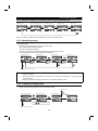
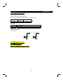
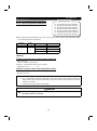
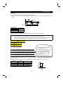
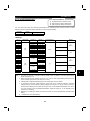
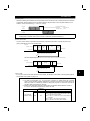
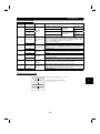
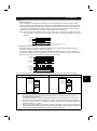
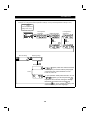
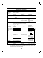
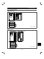
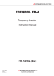
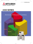
1.3.1 Appearance and structure
(1) Front view
(2) Without front cover
POWER lamp
ALARM lamp
PU connector
(Provided with modular jack type relay connector)
(For use with RS-485 cable for communication)
Modular jack type relay connector compartment
Operation panel (FR-DU04)
Brake resistor *
(Fitted to the back)
Accessory cover
Inboard option mounting position
Wiring port cover for option
Front cover
Main circuit terminal block
Rating plate
Control circuit terminal block
Capacity plate
Wiring cover
*005 and smaller inverters are equipped with an inboard brake resistor.
3
OUTLINE
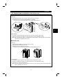
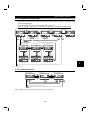
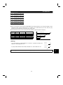
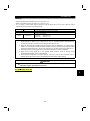
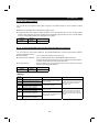
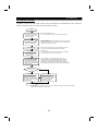
1.3.2 Removal and reinstallation of the front cover
M4500-001 to 010
• Removal
1) Hold both sides of the front cover top and push the front cover down.
2) Hold down the front cover and pull it toward you to remove.
(The front cover may be removed with the PU (FR-DU04/FR-PU04) on.)
Catch
Inverter
1
Front cover
• Reinstallation
1) Insert the catches at the bottom of the front cover into the sockets of the inverter.
2) Using the catches as supports, securely press the front cover against the inverter.
Note: When the operation panel is mounted and the front cover is removed, remove the operation
panel before reinstalling the front cover.
M4500-025 / 040
• Removal
1) Remove the installation screw at top of the front cover.
2) Hold both ends of the front cover top.
3) Pull the front cover toward you to remove.
(The front cover may be removed with the PU (FR-DU04/FR-PU04) on.)
• Reinstallation
1) Insert the catches at the front cover bottom into the sockets of the inverter.
2) Using the catches as supports, securely press the front cover against the inverter.
3) Fix the front cover with the top screw.
Note: When the operation panel is mounted on the front cover removed, remove the operation panel
before reinstalling the front cover.
4
OUTLINE
M4500-060 / 100
• Removal
1) Remove the front cover mounting screws.
• Reinstallation
1) Fix the front cover with the mounting screws.
Note: 1. Make sure that the front cover has been reinstalled securely.
2. The same serial number is printed on the capacity plate of the front cover and the rating plate of
the inverter. Before reinstalling the front cover, check the serial number to ensure that the cover
removed is reinstalled to the inverter from where it was removed.
5
OUTLINE
1.3.3 Removal and reinstallation of the operation panel
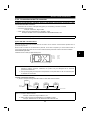
To ensure safety, remove and reinstall the operation panel after switching power off.
• Removal
Hold down the top button of the operation panel and pull the operation panel toward you to remove.
Removal
Reinstallation
1
To reinstall, insert straight and mount securely.
• Reinstallation using the connection cable
1) Remove the operation panel.
2) Disconnect the modular jack type relay connector. (Place the disconnected modular jack type relay
connector in the modular jack type relay connector compartment.)
Modular jack type relay connector
Modular jack type relay connector compartment
3) Securely plug one end of the connection cable into the PU connector (modular jack type relay
connector) of the inverter and the other end into the operation panel.
Note: Install the operation panel only when the front cover is on the inverter.
6
MEMO
CHAPTER 2
INSTALLATION AND WIRING
This chapter gives information on the basic "installation and
wiring" of this product.
Always read the instructions in this chapter before using the
equipment.
2.1 Installation................................................................ 7
2.2 Wiring ...................................................................... 10
2.3 Other wiring ............................................................. 27
Chapter 1
Chapter 2
Chapter 3
Chapter 4
Chapter 5
Chapter 6
Chapter 7
2
2.1 Installation
INSTALLATION AND WIRING
2 INSTALLATION AND WIRING
2.1 Installation
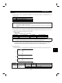
2.1.1 Instructions for installation
1) Handle the unit carefully.
The inverter uses plastic parts. Handle it gently to protect it from damage. Also, hold the unit with even
strength and do not apply too much strength to the front cover alone.
2
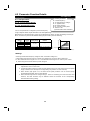
2) Install the inverter in a place where it is immune to vibration. (5.9 m/s {0.6G} or less)
Also note the cart, press, etc.
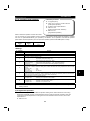
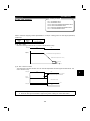
3) Note on ambient temperature
The inverter life is under great influence of ambient temperature. In the place of installation, ambient
temperature must be within the permissible range (depending upon the operation mode and conditions
(see ambient temperature specifications on page 194). Check that the ambient temperature is within that
range in the positions shown in figure 3).
4) Install the inverter on a non-combustible surface.
The inverter will be very hot (maximum about 150°C). Install it on a non-combustible surface (e.g. metal).
Also leave sufficient clearances around the inverter.
5) Avoid high temperature and high humidity.
Avoid direct sunlight and places of high temperature and high humidity.
6) The amount of heat generated in an enclosure can be reduced considerably by placing the heat sink
outside the enclosure.
Note: 1. Use the option (FR-A5CN
) for installation. The mounting area should be cut to the panel
cutting dimensions.
2. The cooling section outside the enclosure has the cooling fan. Do not use the inverter in any
environment where it is exposed to water drops, oil mist, dust, etc.
3. The cable conduit attachment packed with the 060 or 100 is not necessary.
7) Avoid places where the inverter is exposed to oil mist, flammable gases, fluff, dust, dirt etc.
Install the inverter in a clean place or inside a "totally enclosed" panel which does not accept any
suspended matter.
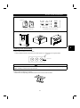
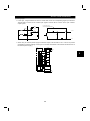
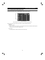
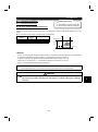
8) Note the cooling method when the inverter is installed in an enclosure.
When two or more inverters are installed or a ventilation fan is mounted in an enclosure, the inverters and
ventilation fan must be installed in proper positions with extreme care taken to keep the ambient
temperatures of the inverters below the permissible value. If they are installed in improper positions, the
ambient temperatures of the inverters will rise and ventilation effect will be reduced.
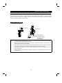
9) Install the inverter securely with screws or bolts in the vertical direction.
5cm
(2 inches)
5cm
(2 inches)
10cm (4 inches)
or more
5cm (2 inches)
or more *
Measurement
position
4) Clearances around the inverter
5cm (2 inches)
or more *
3) Note on ambient temperature
Leave sufficient
clearances above
and under the
inverter to ensure
adequate ventilation.
Cooling fan built
in the inverter
5cm
(2 inches)
Measurement
position
10cm (4 inches)
or more
*: 1cm (0.39 inches) or more for model 005 or less
7
Cooling air
INSTALLATION AND WIRING
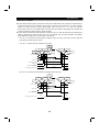
8) For installation in an enclosure
Ventilation fan
Inveter
Inveter
Inveter
Inveter
Inveter
Inveter
Built-in cooling fan
(Correct example)
(Correct example) (Incorrect example)
Position of Ventilation Fan
(Incorrect example)
Accommodation of two or more inverters
9) Vertical mounting
2
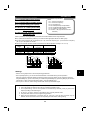
(1) Wiring cover and handling
1) When cable conduits are not connected
Cut the protective bushes of the wiring cover with nippers or a cutter before running the cables.
Wiring cover
Protective bush
WARNING
Do not remove the protective bushes. Otherwise, the cable sheathes may be scratched by the wiring cover
edges, resulting in a short circuit or ground fault.
2) When cable conduits are connected
Remove the corresponding protective bushes and connect the cable conduits.
8
INSTALLATION AND WIRING
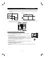
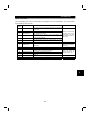
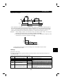
(2) Installation of attachment for conduit connection (060, 100)
An attachment for conduit connection is a standard accessory for models M4500-060 and M4500-100. It is
shipped together with the inverter in one crate. If the inverter is not installed inside an electrical enclosure,
mount this attachment according to the below instructions. If the inverter is mounted inside an electrical
enclosure and conduit is not used, it is not necessary to use this attachment.
1) Preparation
confirm that the following parts are enclosed with the indicated quantity.
No.
1
2
3
4
Name
Conduit connection frame
Cover
Cover installation screw
Cap
Quantity
1
1
4 (M4)
3
2) Installation
(a) Fix with the two installation screws (combined tightening) at the bottom of the inverter unit and the two
screws at the bottom of the attachment.
(b) Install caps on the holes through which wires are not passed.
After installing the cap, bend the metal clasps to fix in position.
Inverter unit
1) Conduit connection frame
2) Cover
4) Cap
3) Cover installation screw
Note: To extend the heat-sink of 060 and 100 models through the back of an enclosure, an adapter model
no. FR-A5CN06 must be used, and it is not possible to use the conduit connection attachment.
9
2.2 Wiring
INSTALLATION AND WIRING
2.2 Wiring
2.2.1 Terminal connection diagram
NFB
Motor
R
U
PU
connector
S
T
3-phase AC power supply
IM
V
W
(RS-485)
Ground
R1
Jumper
S1
24VDC power output and external transistor common
(Contact input common for source logic)
P1
PC
Forward rotation start
STF
Reverse rotation start
STR
Start self-holding selection
Jumper
Remove this jumper when using DC reactor.
P
R (Note)
PX
(Note)
PR
Jumper
Remove this jumper when using
external brake resister.
N
Note: Terminals PR, PX are provided for
M4500-001 to 005.
STOP
A
High
Multi-speed selection Middle
RH
B
RM
Alarm detection
C
Low
Jog mode
Second acceleration/deceleration time selection
RL
JOG
RT
RUN
Running
Output stop
MRS
SU
Up to frequency
Reset
RES
IPF
Instantaneous power failure
Current input selection
AU
OL
Overload
Selection of automatic restart
after instantaneous power failure
CS
FU
Frequency detection
(Contact input common for sink logic)
SD
SE
2
Open collector
outputs
Open collector output common
Common to sink and source
Control input signals (no voltage input allowed)
Frequency setting signals (analog)
10(+5V)
3
Frequency setting
potentiometer
1/2W1kW
Meter
(e.g. frequency meter)
+
-
10E(+10V)
2
2
1
FM
0 to 5VDC
Selected
0 to 10VDC
5 (Analog common)
Moving-coil type
1mA full-scale
SD
AM
(+)
5
(-)
Analog signal output
(0 to 10VDC)
Common
Auxiliary input
Current input
0 to ± 5VDC
1 0 to ±10VDC Selected
Ground
4 (4 to 20mADC)
Main circuit terminal
Control circuit input terminal
Control circuit output terminal
10
INSTALLATION AND WIRING
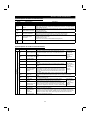
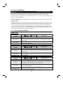
(1) Description of main circuit terminals
Symbol
R, S, T
U, V, W
Terminal Name
AC power input
Inverter output
Description
Connect to the commercial power supply.
Connect a three-phase squirrel-cage motor.
Connected to the AC power supply terminals R and S. To retain the alarm display and
alarm output, remove the jumpers from terminals R-R1 and S-S1 and apply external
power to these terminals.
Disconnect the jumper from terminals PR-PX and connect the external brake resistor
across terminals P-PR.
(Provided for 010 or less.)
R1, S1
Power supply for control
circuit
P, PR
Brake resistor connection
P, P1
Power factor improving
DC reactor connection
Disconnect the jumper from terminals P-P1 and connect the DC reactor.
PR, PX
Built-in brake circuit
connection
When the jumper is connected across terminals PX-PR (factory setting),
the built-in brake circuit is valid.
(Provided for 010 or less.
010 does not have the built-in brake resistor and the jumper.)
Ground
For grounding the inverter chassis. Must be earthed.
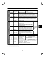
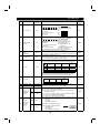
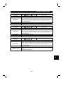
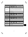
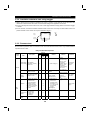
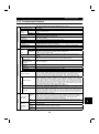
(2) Description of control circuit terminals
Type
Symbol
Contacts, e.g. start (STF), stop (STOP) etc.
Description
Turn on the STF signal to start forward rotation and turn it off to
stop. Acts as a programmed operation start signal in the
programmed operation mode. (Turn on to start and turn off to
stop.)
When the STF
and STR signals
are turned on
simultaneously,
the stop
command is
given.
STF
Forward rotation start
STR
Reverse rotation start
Turn on the STR signal to start reverse rotation and turn it off to
stop.
STOP
Start self-holding
selection
Turn on the STOP signal to select the self-holding of the start signal.
RH, RM, RL
Input signals
Terminal Name
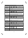
JOG
RT
MRS
RES
AU
CS
SD
PC
Use the RH, RM and RL signals as appropriate to select multiple
speeds.
Input terminal
Turn on the JOG signal to select jog operation (factory setting).
function selection
JOG mode selection Jog operation can be performed with the start signal (STF or
(Pr. 180 to
STR).
Pr. 186) change
Turn on the RT signal to select the second acceleration/
terminal
Second acceleration/ deceleration time. When the second functions such as "second
deceleration time
torque boost" and "second V/F (base frequency)" functions have functions.
selection
been set, these functions can also be selected by turning on the
RT signal.
Turn on the MRS signal (20ms or longer) to stop the inverter output.
Output stop
Used to shut off the inverter output to bring the motor to a stop by the magnetic
brake.
Used to reset the protective circuit activated. Turn on the RES signal for more than
Reset
0.1 second, then turn it off.
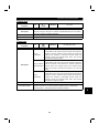
Current input
Only when the AU signal is turned on, the inverter can be
Input terminal
selection
operated with the 4-20mADC frequency setting signal.
function selection
(Pr. 180 to
With the CS signal on, restart can be made automatically when
Automatic restart after
Pr. 186) change
the power is restored after an instantaneous power failure. Note
instantaneous power
terminal
that this operation requires restart parameters to be set. When
failure selection
the inverter is shipped from the factory, it is set to disallow restart. functions.
Contact input
Common to the contact input terminals and terminal FM. Common output terminal for
common (sink)
24VDC 0.1A power (PC terminal).
24VDC power and
When transistor output (open collector output), such as a programmable controller, is
external transistor
connected, connect the external power supply common for transistor output to this
common
terminal to prevent a fault caused by leakage current. This terminal can be used as a
Contact input
24VDC, 0.1A power output. When source logic has been selected, this terminal
common (source)
serves as a contact input common.
Multi-speed selection
11
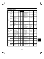
INSTALLATION AND WIRING
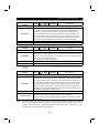
Type
Symbol
Terminal Name
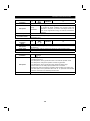
10E
*1:
*2:
*3:
Analog frequency setting
Frequency setting
(voltage)
4
Frequency setting
(current)
1
Auxiliary frequency
setting
5
Frequency setting
input common
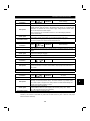
A, B, C
Alarm output
Inverter running
SU
Up to frequency
OL
Overload alarm
IPF
Instantaneous power
failure
FU
Frequency detection
SE
Open collector output
common
Pulse
RUN
For meter
Analog
Open collector
2
FM
AM
Analog signal output
Common to the RUN, SU, OL, IPF and FU terminals.
Factory setting of output item:
Frequency
One selected from 16
Permissible load current 1mA
monitoring items, such as
1440 pulses/second at 60Hz
output frequency, is output. (*3)
The output signal is
Factory setting of output item:
proportional to the magnitude
Frequency
of each monitoring item.
Output signal 0 to 10VDC
Permissible load current 1mA
With the operation panel connector, communication can be made through RS-485.
RS-485
Communication
Output signals
Contact
Input signals
10
Frequency setting
power supply
Description
When the frequency setting potentiometer is
connected in the factory-set state, connect it to
terminal 10.
5VDC, permissible load current
When it is connected to terminal 10E, change the
10mA
input specifications of terminal 2.
By entering 0 to 5VDC (0 to 10VDC), the maximum output frequency is reached at 5V
(or 10V) and I/O are proportional. Switch between input 0 to 5VDC (factory setting)
and 0 to 10VDC from the operation panel. Input resistance 10kΩ. Maximum
permissible voltage 20V.
By entering 4 to 20mADC, the maximum output frequency is reached at 20mA and
I/O are proportional. This input signal is valid only when the AU signal is on. Input
resistance 250Ω. Maximum permissible current 30mA.
By entering 0 to ±5VDC 0 to ±10VDC, this signal is added to the frequency setting
signal of terminal 2 or 4. Switch between input 0 to ±5VDC and 0 to ±10VDC (factory
setting) from the operation panel. Input resistance 10kΩ. Maximum permissible
voltage ±20V.
Common to the frequency setting signal (terminal 2, 1 or 4) and analog output
terminal AM. Do not earth.
Change-over contact output indicating that the output has been
stopped by the inverter protective function activated.
200VAC 0.3A, 30VDC 0.3A. Alarm: discontinuity across B-C
(continuity across A-C), normal: continuity across B-C
(discontinuity across A-C).
Switched low when the inverter output frequency is equal to or
higher than the starting frequency (factory set to 0.5Hz, variable).
Switched high during stop or DC dynamic brake operation (*2).
Permissible load 24VDC 0.1A.
Output terminal
Switched low when the output frequency has reached within
function selection
±10% of the set frequency (factory setting, variable). Switched
(Pr. 190 to
high during acceleration, deceleration or stop (*2). Permissible
Pr. 195) change
load 24VDC 0.1A.
terminal
Switched low when the stall prevention function has caused stall functions.
prevention to be activated. Switched high when stall prevention is
reset (*2). Permissible load 24VDC 0.1A.
Switched low when instantaneous power failure or under voltage
protection is activated (*2). Permissible load 24VDC 0.1A.
Switched low when the output frequency has reached or
exceeded the detection frequency set as appropriate. Switched
high when below the detection frequency (*2). Permissible load
24VDC 0.1A
10VDC, permissible load
current 10mA
PU connector
· Conforming Standard : EIA Standard RS-485
· Transmission format : Multi-drop link
· Communication speed : Maximum 19200 baud rates
: 500m
· Overall length
Terminals PR and PX are provided for the M4500-001 to 010
Low indicates that the open collector outputting transistor is on (conducts). High indicates that the
transistor is off (does not conduct).
Not output while the inverter is reset.
12
2
INSTALLATION AND WIRING
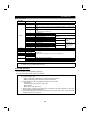
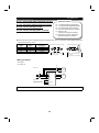
2.2.2 Wiring of the main circuit
(1) Wiring instructions
1) Crimping terminals with insulation sleeves are recommended for use with the power and motor cables.
2) Cut the protective bushes of the wiring cover when running the cables.
3) Power must not be applied to the output terminals (U, V, W) of the inverter. Otherwise the inverter will be
damaged.
4) After wiring, wire off-cuts must not be left in the inverter.
Wire off-cuts can cause an alarm, failure or malfunction. Always keep the inverter clean.
When drilling mounting holes in a control box etc., exercise care to prevent chips and other foreign matter
from entering the inverter.
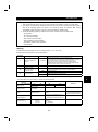
5) Use cables of the recommended size for wiring to make the voltage drop 2% or less.
If the wiring distance is long between the inverter and motor, a main circuit cable voltage drop will cause
the motor torque to decrease especially at the output of a low frequency.
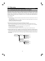
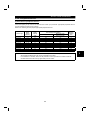
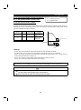
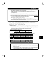
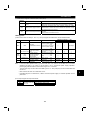
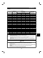
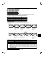
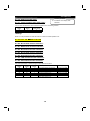
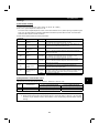
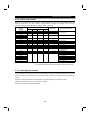
6) The overall wiring length should be 500m (1640.40feet) maximum.
Especially for long distance wiring, the fast-response current limit may be misactivated under the influence
of a charging current due to the stray capacitance of the wiring. The fast-response current limit must be
turn off by Pr.156 when the total wiring length is more than the indicated value in the following table for
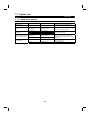
M4500-010 to 005.
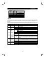
Inverter Model
Non-low acoustic noise mode
Low acoustic noise mode
001
100m (328 feet)
100m (328 feet)
003
300m (984 feet)
200m (656 feet)
005
300m (984 feet)
300m (984 feet)
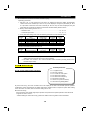
Even though the fast-response current limit is turned off , in more long distance wiring situations the over
current protection may be misactivated or the devices connected to the output side may misoperate or
become faulty under the influence of a charging current due to the stray capacitance of the wiring.
Therefore, the maximum overall wiring length should be as indicated in the following table. (When two or
more motors are connected to the inverter, the total wiring length should be within the indicated value.)
Inverter Model
Total wiring length
001
100m (328 feet)
003
300m (984 feet)
005 or more
500m (1640 feet)
Overall wiring length (005 or more)
500m
(1640 feet) maximum
300m
(984 feet)
300m
(984 feet)
300m (984 feet) + 300m (984 feet) = 600m (1968 feet)
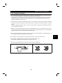
7) Connect only the recommended external brake resistor between the terminals P and PR. These terminals
must not be shorted.
13
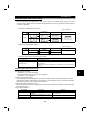
INSTALLATION AND WIRING
8) Electromagnetic wave interference
The input/output (main circuit) of the inverter includes harmonic components, which may interfere with the
communication devices (such as AM radios) used near the inverter. In this case, install FR-BSF01 or FR-BLF
line noise filter to minimize interference.
9) Do not install a power capacitor, surge suppressor in the output side of the inverter.
This will cause the inverter to trip or the capacitor and surge suppressor to be damaged. If any of the above
devices are installed, immediately remove them. (If capacitor type filter is connected, switching power off during
motor operation may result in E.UVT. In this case, connect the capacitor type filter in the primary side of the
electromagnetic contactor.)
10)When rewiring after operation, make sure that the POWER lamp has gone off, and when more than 10 minutes
have elapsed after power-off, check with a meter that the voltage is zero. After that, start rewiring work. For
some time after power-off, there is a dangerous voltage in the capacitor.
CAUTION
Do not use residual current protective device as the only protection against indirect
contact.
Protective earth connection essential.
Do not connect more than 2 wires on the protective earth terminal.
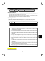
Notes on Grounding
• Leakage currents flow in the inverter. To prevent an electric shock, the inverter and motor must be
grounded.
• Use the dedicated ground terminal to ground the inverter. (Do not use the screw in the case, chassis,
etc.)
(Unit: mm2)
• The ground cable should be as thick as possible.
Ground Cable
Motor Capacity
Its gauge should be equal to or larger than those
Gauge
indicated in the following table. The grounding 3.7kW (5HP) or less
3.5
5.5
point should be as near as possible to the inverter 7.5kW (10HP)
15kW (20HP)
14
to minimize the ground cable length.
22 kW (30HP), 37kW (50HP)
22
• Ground the motor on the inverter side using one 55kW (75HP)
38
wire of the 4-core cable.
14
2
INSTALLATION AND WIRING
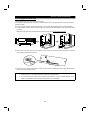
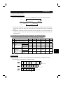
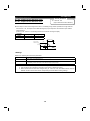
(2) Terminal block layout
In the main circuit of the inverter, the terminals are arranged as shown below:
M4500-001 to 010
M4500-060, 100
R1
S1
R
Screw size (M4)
Charge lamp
S
Charge lamp
R
S
T
U
V
N
P1
P
PR
PX
screw size (M5)
R
S
Screw size (M8)
Jumpers
T
U
V
V
W
S
N
Screw size (M4)
P1
P
Screw size (M4)
Charge lamp
S
U
S1
R
W
M4500-025, 040
R
T
R1
W
N
R1
S1
R
S
P1
P
Screw size (M4)
Screw size (M6)
Jumper
Screw size (M6)
Note: 010 does not have the jumper across the terminals PR-PX.
15
Jumper
Screw size (M8)
INSTALLATION AND WIRING
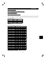
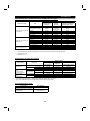
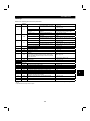
(3) Cables, crimping terminals, etc.
The following table lists the cables and crimping terminals used with the inputs (R, S, T) and outputs
(U, V, W) of the inverter and the torque for tightening the screws:
Applicable Inverter
Type
M4500-001
-003
-005
M4500-010
M4500-025
M4500-040
M4500-060
M4500-100
Terminal
Screw Size
Tightening Torque
N⋅⋅ m (Kgf ⋅ c m)
M4
M4
M6
M6
M8
M8
Cables (Note 1)
Crimping Terminals
AWG
mm2
R, S, T
U, V, W
R, S, T
U, V, W
R, S, T
U, V, W
1 (15)
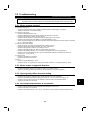
2-4
2-4
2
2
14
14
1 (15)
4 (45)
4 (45)
7 (80)
7 (80)
5.5-4
5.5-6
14-6
22-8
38-8
2-4
5.5-6
14-6
22-8
38-8
3.5
5.5
14
22
38
2
5.5
14
22
38
12
10
6
4
2
14
10
6
4
2
Note: 1. The cables used should be 75°C (167°F) copper cables.
2. Tighten the terminal screws to the specified torque.
Undertightening can cause a short or misoperation.
Overtightening can cause the screws and unit to be damaged, resulting in a short or
misoperation.
(4) Connection of the power supply and motor
Power
supply
R
Ground
terminal
No-fuse
breaker
S
R
T
S
U
T
V
U
2
W
V
W
Motor
Ground
Ground
Connect the motor to U, V, W.
In the above connection,
turning on the forward rotation
switch (signal) rotates the motor
in the counterclockwise (arrow)
direction when viewed from
the load shaft.
The power supply cables
must be connected to R, S, T.
If they are connected to U, V,
W, the inverter will be damaged.
Phase sequence need not be
matched.
For use with a single-phase
power supply,the power supply
cables must be connected to
R and S.
16
INSTALLATION AND WIRING
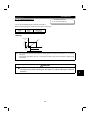
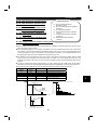
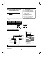
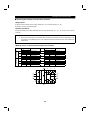
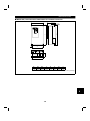
(5) Connecting the control circuit to a power supply separately from the main circuit
If the magnetic contactor (MC) in the inverter power supply is opened when the protective circuit is operated,
the inverter control circuit power is lost and the alarm output signal cannot be kept on. To keep the alarm
signal on terminals R1 and S1 are available. In this case, connect the power supply terminals R1 and S1 of
the control circuit to the primary side of the MC.
• Model M4500-001 to 100
<Connection procedure>
R1
S1
Power supply terminal
block for control circuit
R
S
Power supply terminal
block for control circuit
T
MC
1) Loosen the upper screws.
2) Remove the lower screws.
3) Pull out and remove the jumper.
4) Connect the separate power supply
cables for control circuit to the
upper terminals (R1, S1). (Note 4)
Main power supply
Note: 1. When the main circuit power (R, S, T) is on, do not switch off the control power (terminals R1,
S1). Otherwise the inverter may be damaged.
2. When using a separate power supply, the jumpers across R-R1 and S-S1 must be removed.
Otherwise the inverter may be damaged.
3. For a different power supply system which takes the power of the control circuit from other than
the primary side of the MC, the voltage should be equal to the main circuit voltage.
4. The power supply cables must not be connected to the lower terminals. If connected, the inverter
may be damaged.
5. Entering the start signal with power supplied to only the R1 and S1 terminals will result in an error
display (E.OC1).
17
INSTALLATION AND WIRING
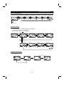
2.2.3 Wiring of the control circuit
(1) Wiring instructions
1) Terminals SD, SE and 5 are common to the I/O signals and isolated from each other. These common
terminals must not be connected to each other or earthed.
2) Use shielded or twisted cables for connection to the control circuit terminals and run them away from the
main and power circuits (including the 200V relay sequence circuit).
3) The frequency input signals to the control circuit are micro currents. When contacts are required, use two
or more parallel micro signal contacts or a twin contact to prevent a contact fault.
2
4) It is recommended to use the cables of 0.75mm gauge for connection to the control circuit terminals.
2
If the cable gauge used is 1.25mm or more, the front cover may be lifted when there are many cables
running or the cables are run improperly, resulting in an operation panel or parameter unit contact fault.
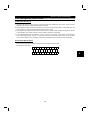
(2) Terminal block layout
In the control circuit of the inverter, the terminals are arranged as shown below:
Terminal screw size: M3.5
B
A
RL
SE
C
RM
RUN
PC
RH
SU
AM
RT
IPF
10E
AU
OL
10
2
STOP MRS
FU
SD
5
RES
STF
4
SD
STR
1
FM
JOG
CS
2
18
INSTALLATION AND WIRING
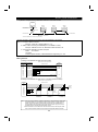
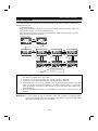
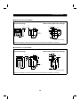
(3) Changing the control logic
The input signal logic is factory-set to the sink mode.
To change the control logic, the connector on the back of the control circuit terminal block must be moved to
the other position.
(The output signals may be used in either the sink or source logic independently of the connector position.)
1) Loosen the two mounting screws in both ends of the control circuit terminal block. (The screws cannot be
removed.)
With both hands, pull down the terminal block from the back of the control circuit terminals.
2) Remove the connector from the rear surface of the control circuit terminal block and place in required
Logic position (either Sink or Source).
C ON
2
2
SOU
RCE
3 S
INK
CON
CON
SOU
RCE
C ON
3 S
INK
CON1
3) Using care not to bend the pins of the control circuit connector, reinstall the control circuit terminal block
and fix it with the mounting screws.
Note: 1. Make sure that the control circuit connector is fitted correctly.
2. While power is on, never disconnect the control circuit terminal block.
3. The sink-source logic change-over connector must be fitted in only one of those positions. If it is
fitted in both positions at the same time, the inverter may be damaged.
19
INSTALLATION AND WIRING
4) Sink logic type
• In this logic, a signal switches on when a current flows out of the corresponding signal input terminal.
Terminal SD is common to the contact input signals. Terminal SE is common to the open collector
output signals.
A current flows out of
the corresponding signal RUN
R
Current
STF
RUN
R
STR
SD
SE
• When using an external power supply for transistor output, use terminal PC as a common to prevent
misoperation caused by leakage current. (Do not connect terminal SD of the inverter with terminal 0V of
the external power supply.)
Inverter
PLC
Transistor output
module
STF
STR
RH
RM
RL
RES
PC
DC24V SD
20
DC24V
(SD)
2
INSTALLATION AND WIRING
5) Source logic type
• In this logic, a signal switches on when a current flows into the corresponding signal input terminal.
Terminal PC is common to the contact input signals. Terminal SE is common to the open collector
output signals.
A current flows out of
the corresponding signal RUN
PC
Current
STF
RUN
R
STR
R
SE
• When using an external power supply for transistor output, use terminal SD as a common to prevent
misoperation caused by leakage current.
PLC
Inverter
PC
STF
DC24V
(SD)
DC24V
STR
SD
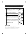
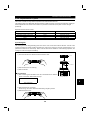
(4) How to use terminals "STOP", "CS" and "PC"
1) Using the "STOP" terminal
A connection example (for sink logic) for self-holding the start signal (forward
rotation, reverse rotation) is shown on the right.
STOP
MRS
Stop
RES
2) Using the "CS" terminal
This terminal is used to perform automatic restart after instantaneous power failure
and commercial power supply-inverter switch-over operation.
<Example: Automatic restart after instantaneous power failure in sink logic>
Connect terminals CS-SD and set a value other than "9999" in Pr. 57 "coasting time
for automatic restart after instantaneous power failure".
SD
Forward
rotation
Reverse
rotation
STF
STR
CS
SD
(Short)
3) Using the "PC" terminal
This terminal can be used as 24VDC power output using SD as a common terminal.
Specifications: 18V to 26VDC, 0.1A permissible current
Note that the wiring length should be within 30m.
Do not short terminals PC-SD.
When terminal PC is used as a 24V power supply, leakage current from transistor output cannot be
prevented.
21
INSTALLATION AND WIRING
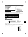
2.2.4 Connection to the PU connector
(1) When connecting the operation panel or parameter unit using a connection cable
<Recommended cable connector>
• Parameter unit connection cable (FR-CB2) (option) or the following connector and cable.
• Connector: RJ45 connector
Example: 5-554720-3, Nippon AMP
• Cable: Cable conforming to EIA568 (e.g. 10BASE-T cable)
Example: SGLPEV 0.5mm×4P, MITSUBISHI CABLE INDUSTRIES, LTD.
Note: The maximum wiring length is 20m (65.62 feet).
(2) For RS-485 communication
With the operation panel disconnected, the PU connector can be used for communication operation from a
personal computer etc.
When the PU connector is connected with a personal, FA or other computer by a communication cable, a
user program allows the inverter to be run and monitored and the parameter values to be read and written.
<PU connector pin-outs>
Viewed from the inverter (receptacle side) front
1) SG
2) P5S
3) RDA
4) SDB
8)
5) SDA
6) RDB
7) SG
8) P5S
1)
Note: 1. Do not connect the PU connector to the computer's LAN board, FAX modem socket or
telephone modular connector. Otherwise, the product may be damaged due to electrical
specification differences.
2. Pins 2) and 8) (P5S) provide power to the operation unit or parameter unit. Do not use these pins
for RS-485 communication.
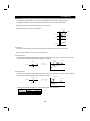
<System configuration example>
1) When a computer having a RS-485 interface is used with several inverters
Computer
RS-485
interface/terminal
Station 1
Station 2
Inverter
Inverter
Station n
Inverter
PU connector
(Note 1)
PU connector
(Note 1)
PU connector
(Note 1)
10BASE-T
cable (Note 2)
Terminal resistor
Distribution terminal
Use the connector and cables which are available on the market.
Note: 1. Connector: RJ45 connector
Example: 5-554720-3, Nippon AMP Co., Ltd.
2. Cable: Cable conforming to EIA568B (such as 10BASE-T cable)
Example: SGLPEV 0.5mm×4P, Mitsubishi Cable Industries, Ltd.
22
2
INSTALLATION AND WIRING
2) When a computer having a RS-232C interface is used with inverters
Computer
RS-232C connector
RS-232C cable
Max. 15m
*Converter
Station 1
Station 2
Station n
Inverter
Inverter
Inverter
PU connector
(Note 1)
PU connector
(Note 1)
PU connector
(Note 1)
RS-485 terminal
Terminal resistor
Distribution terminal
10BASE-T cable (Note 2)
*Converter available on the market is required. (Note 3)
Use the connector, cables and converter, which are available on the market.
Note: 1. Connector: RJ45 connector
Example : 5-554720-3, Nippon AMP Co., Ltd.
2. Cable: Cable conforming to EIA568B (such as 10BASE-T cable)
Example : SGLPEV 0.5mm×4P, Mitsubishi Cable Industries, Ltd.
3. *Commercially available converter examples:
Model : FA-T-RS40
Converter
Industrial System Division., Mitsubishi Electric Engineering Co., Ltd.
<Wiring method>
1) Wiring of one RS-485 computer and one inverter
Cable connection and signal direction
Computer Side Terminals
Inverter
Signal name
Description
RDA
Receive data
SDA
RDB
Receive data
SDB
SDA
Send data
RDA
SDB
Send data
RDB
RSA
Request to send
RSB
Request to send
CSA
Able to send
CSB
Able to send
SG
Signal ground
FG
Frame ground
PU connector
10BASE-T Cable
Note 2
0.3mm2 or more
SG
2) Wiring of one RS-485 computer and "n" inverters (several inverters)
Cable connection and signal direction
Computer
10BASE-T Cable
RDA
RDB
Terminal
resistor
(Note 1)
SDA
SDB
CSB
SG
FG
SG
SG
SDA
SDB
Terminal
resistor
jumper (*1)
RDA
RDB
SDA
SDB
RDA
RDB
SDA
Note 2
SDB
CSA
RDA
RSB
RDB
RSA
SG
Station 1
Station 2
Station 3
Inverter
Inverter
Inverter
Note: 1. There may be the influence of reflection depending on the transmission speed and/or
transmission distance. If this reflection hinders communication, provide a terminal
resistor. If the PU connector is used to make a connection, use a distributor as a
terminal resistor cannot be fitted. Connect the terminal resistor only to the inverter
remotest from the computer.(Terminal resistor: 100 Ω)
2. Make connections in accordance with the instruction manual of the computer used.
Fully check the terminal numbers of the computer as they differ between models.
23
INSTALLATION AND WIRING
2.2.5 Connection of brake resistor and DC reactor
Incorrect connection will cause inverter damage or accident.
(1) Connection of the external brake resistor (010 or less)
The built-in brake resistor is connected across terminals P and PR. Fit the external brake resistor instead
when the built-in brake resistor does not have enough thermal capability for high-duty operation. Remove the
jumper from across terminals PR-PX and connect the external brake resistor across terminals P-PR.
(For the positions of terminals P and PR, refer to the terminal block arrangement (page15).)
The external brake resistor should be as listed in the following table. Selected the rated power of the brake
resistor according to the brake duty.(The rated power indicated below assumes that the brake resistor duty is
10%)
Inverter size
Brake resistance
Reference rated power at brake duty of 10%
0.75K
1000 ohm minimum
180W minimum
2.2K
350 ohm minimum
500W minimum
3.7K
200 ohm minimum
800W minimum
7.5K
110 ohm minimum
1600W minimum
Note: 1. The brake resistor connected should only be the dedicated brake resistor.
2. The jumper across terminals PR-PX must be disconnected before connecting the dedicated
brake resistor. A failure to do so may damage the inverter.
3. The 010 model does not have the built-in brake resistor and the jumper across terminals PR-PX.
• Model ..............M4500-001 to 010
1) Remove the screws in terminals PR and PX and remove the jumper.
2) Connect the brake resistor across terminals P-PR.
(The jumper should remain disconnected.)
Removal of jumper
FR-A560-0.75 to 7.5K-NA
Terminal P
Terminal PR
Terminal PR
Jumper
Terminal PX
24
2
INSTALLATION AND WIRING
(2) Connection of the power factor improving DC reactor
Connect the power factor improving DC reactor <Connection method>
between terminals P1-P. In this case, the jumper
P1
connected across terminals P1-P must be
removed. Otherwise, the reactor will not function.
Remove
P
the jumper.
Note: 1. The wiring distance should be within 5m.
2. The size of the cables used should be equal to or larger than that of the power supply cables
(R, S, T).
25
INSTALLATION AND WIRING
2.2.6 Design information
1) For commercial power supply-inverter switch-over operation, provide electrical and mechanical interlocks
for MC1 and MC2 designed for commercial power supply-inverter switch-over.
When there is a commercial power supply-inverter switch-over circuit as shown below, the inverter will be
damaged by leakage current from the power supply due to arcs generated at the time of switch-over or
chattering caused by a sequence error.
2) If the machine must not be restarted when power is restored after a power failure, provide a magnetic
contactor in the inverter's primary circuit and also make up a sequence which will not switch on the start
signal.
If the start signal (start switch) remains on after a power failure, the inverter will automatically restart as
soon as the power is restored.
3) When the power supply used with the control circuit is different from the one used with the main circuit,
make up a circuit which will switch off the main circuit power supply terminals R, S, T when the power
supply terminals R1, S1 for the control circuit are switched off.
4) Since the input signals to the control circuit are on a low level, use two parallel micro signal contacts or a
twin contact for contact inputs to prevent a contact fault.
5) Do not apply a large voltage to the contact input terminals (e.g. STF) of the control circuit.
2
6) Do not apply a voltage directly to the alarm output signal terminals (A, B, C).
Always apply a voltage to these terminals via a relay coil, lamp, etc.
7) Make sure that the specifications and rating match the system requirements.
1) Commercial power supply-inverter switch-over
4) Low-level signal contacts
MC1
Interlock
Power
supply
R
U
S
V
T
W
IM
MC2
Leakage current
Inverter
Low-level signal contacts
26
Twin contact
2.3 Other wring
INSTALLATION AND WIRING
2.3 Other wiring
2.3.1 Inverter-generated noises and reduction techniques
Some noises enter the inverter causing it to misoperate and others are radiated by the inverter causing
misoperation of peripheral devices. Though the inverter is designed to be insusceptible to noise, it handles
low-level signals, so it requires the following basic measures to be taken. Also, since the inverter chops the
output at a high carrier frequency, it could generate noise. If these noises cause peripheral devices to
misoperate, measures should be taken to suppress the noise. The measures differ slightly depending on
noise propagation paths.
1) Basic measures
• Do not run the power cables (I/O cables) and signal cables of the inverter in parallel with each other and
do not bundle them.
• Use twisted shielded cables for the detector connection and control signal cables and connect the
sheathes of the shielded cables to terminal SD.
• Ground the inverter, motor, etc. at one point.
2) Measures against noises which enter and cause misoperation of the inverter
When devices which generate many noises (which use magnetic contactors, magnetic brakes, many
relays, for example) are installed near the inverter and the inverter may be effected by noise, the following
measures must be taken:
• Provide surge suppressors for devices that generate noise to suppress noise.
• Fit data line filters (refer to page 29) to signal cables.
• Ground the shields of the detector connection and control signal cables with cable clamp metal.
3) Measures against noise which is radiated by the inverter causing misoperation of peripheral devices.
Inverter-generated noise is largely classified into those radiated by the cables connected to the inverter and
inverter main circuit (I/O), those electromagnetically and electrostatically inducted to the signal cables of
the peripheral devices close to the main circuit power supply, and those transmitted through the power
supply cables.
Inverter-generated
noise
Air-propagated
noise
Noise directly radiated by inverter
Path 1)
Noise radiated by
power cables
Path 2)
Noise radiated by
motor cables
Path 3)
Magnetic induction
Path 4),5)
noise
Static induction
noise
Cable-propagated
noise
Path 6)
Noise propagated
through power
cables
Path 7)
Noise from ground
cable due to
Path 8)
leakage current
27
INSTALLATION AND WIRING
5)
Telephone
7)
7)
2)
1)
Instrument
Receiver
2) Sensor power supply
In3) verter
6)
4)
Motor
Noise Path
1) 2) 3)
4) 5) 6)
7)
8)
IM
8)
3)
Sensor
Measures
When devices which handle low-level signals and are susceptible to misoperation due to noise (such as
instruments, receivers and sensors) are installed near the inverter and their signal cables are contained in the
same panel as the inverter or are run near the inverter, the devices may be effected by air-propagated noises
and the following measures must be taken:
(1) Install easily affected devices as far away as possible from the inverter.
(2) Run easily affected signal cables as far away as possible from the inverter.
(3) Do not run the signal cables and power cables (inverter I/O cables) in parallel with each other and do not
bundle them.
(4) Inset line noise filters into I/O and capacitor type filter into input side to suppress cable-radiated noises.
(5) Use shielded cables for signal cables and power cables and run them in individual metal conduits to reduce
further effects.
When the signal cables are run in parallel with or bundled with the power cables, magnetic and static induction
noise may be propagated to the signal cables to effect the devices and the following measures must be taken:
(1) Install easily affected devices as far away as possible from the inverter.
(2) Run easily affected signal cables as far away as possible form the inverter.
(3) Do not run the signal cables and power cables (inverter I/O cables) in parallel with each other and do not
bundle them.
(4) Use shield cables for signal cables and power cables and run them in individual metal conduits to reduce
further effects.
When the power supplies of the peripheral devices are connected to the power supply of the inverter within the
same line, inverter-generated noise may flow back through the power supply cables to misoperate the devices
and the following measures must be taken:
(1) Install the capacitor type filter to the power cables (I/O cables) of the inverter.
(2) Install the line noise filter (FR-BLF, FR-BSF01) to the power cables (I/O cables) of the inverter.
When a closed loop circuit is formed by connecting the peripheral device wiring to the inverter, leakage current
may flow through the ground cable of the inverter to effect the device. In such a case, disconnection of the
ground cable of the device may cause the device to operate properly.
28
2
INSTALLATION AND WIRING
z Data line filter
Noise entry can be prevented by providing a data line filter for the detector cable etc.
z Example of measures against noises
Control box
Reduce carrier
frequency.
Install filter (FR-BLF,FRBSF01) to inverter input side.
Install filter (FR-BLF,FR-BSF01)
to inverter output side.
FRBLF
Inverter power
supply
Inverter
FRBLF
Motor
Install capactor type filter
to inverter input side.
Use 4-core cable for motor
power cable and use one
cable as ground cable.
Separate inverter and power line
30cm (11.81 inches) or more
(at least 10cm (3.94 inches))
from sensor circuit.
Use twisted pair
shielded cable.
Sensor
Power
supply for
sensor
Control power
supply
Do not ground shield but connect
it to signal common cable.
Do not ground control box directly.
Do not ground control cable.
29
INSTALLATION AND WIRING
2.3.2 Leakage currents and countermeasures
Due to the static capacitance existing in the inverter I/O wiring and motor, leakage currents flow through
them. Since their values depend on the static capacitance, carrier frequency, etc., take the following
measures.
(1) To-ground leakage currents
Leakage currents may flow not only into the inverter's own line but also into the other line through the ground
cable, etc. These leakage currents may operate earth leakage circuit breakers and earth leakage relays
unnecessarily.
• Countermeasures
Decrease the carrier frequency (Pr. 72) of the inverter.
Note that motor noise increases. Selection of Soft-PWM (Pr. 240) will make it unoffending.
By using earth leakage circuit breakers designed for harmonics and surges (e.g. Mitsubishi's Progressive
Super Series) in the inverter's own line and other line, operation can be performed with low noise (with
the carrier frequency kept high)
⋅
⋅
• To-ground leakage current
Note that a long wiring length will increase leakage currents. Decrease the carrier frequency of the
inverter to reduce leakage currents.
Higher motor capacity leads to larger leakage currents. Larger leakage currents occur in 575V class than
in 200V and 400V class.
⋅
⋅
(2) Line-to-line leakage currents
Harmonics of leakage currents flowing in static capacities between the inverter output cables may operate the
external thermal relay unnecessarily. When the wiring length is long (50m (164.04 feet) or more) for the
small-capacity model (7.5kW (10HP) or less), the external thermal relay is likely to operate unnecessarily
because the ratio of the leakage current to the rated motor current increases.
• Line-to-Line Leakage Current Data Example
Motor Capacity
(kW (HP))
Rated Motor
Current (A)
0.4 (1/2)
0.75 (1)
1.5 (2)
2.2 (3)
3.7 (5)
5.5 (7.5)
7.5 (10)
1.8
3.2
5.8
8.1
12.8
19.4
25.6
Leakage Current (mA)
Wiring length 50m
Wiring length 100m
(164.04 feet)
(328.08 feet)
930
1500
1020
1590
1110
1680
1200
1770
1320
1890
1470
2040
1605
2175
Thermal relay
NFB
Power
supply
Motor: Mitsubishi Electric
SF-JR 4P
Carrier frequency: 14.5Hz
2
Cable used: 2mm 4-core
cable
Motor
IM
Inverter
Line static capacitances
Line-to-Line Leakage Current Path
• Countermeasures
Use the electronic overcurrent protection (Pr. 9) of the inverter.
Decrease the carrier frequency. Note that motor noise increases. Selection of Soft-PWM (Pr. 240) will
make it unoffending.
To ensure that the motor is protected against line-to-line leakage currents, it is recommended to use a
temperature sensor to directly detect motor temperature.
⋅
⋅
30
2
INSTALLATION AND WIRING
2.3.3 Inverter-driven 575V class motor
Voltage at a motor terminal (%)
In the PWM type inverter, a surge voltage attributable to wiring constants is generated at the motor terminals.
Especially for a 575V class motor, the surge voltage may deteriorate the insulation.
200
150
100%
0
10
20 30
40
50
60
70
80
90 100
Motor wiring length (m)
Surge voltage at a motor terminal by motor wiring length (reference)
When the 575V class motor is driven by the inverter, consider the following measures:
• Measures
(1) Inverter duty motor
Select an inverter duty motor. Many motor manufacturers sell motors with insulation systems designed
to withstand the stress imposed by PWM inverters.
(2) AC reactor
For added protection, install an AC reactor on the inverter output.
31
INSTALLATION AND WIRING
2.3.4 Peripheral devices
(1) Selection of peripheral devices
Check the capacity of the motor to be used with the inverter you purchased. Appropriate peripheral devices
must be selected according to the capacity.
Refer to the following list and prepare appropriate peripheral devices:
Inverter Type
M4500-001
M4500-003
M4500-005
M4500-010
M4500-010
M4500-025
M4500-025
M4500-040
M4500-040
M4500-060
M4500-060
M4500-100
Motor
Output
(kW (HP))
0.75 (1)
2.2 (3)
3.7 (5)
5.5 (7.5)
7.5 (10)
11 (15)
15 (20)
18.5 (25)
22 (30)
30 (40)
37 (50)
55 (75)
Power
Supply
Capacity
(kVA)
2.5
5.5
9
12
17
20
28
34
41
52
66
100
Rated current of No-Fuse Breaker or
Earth Leakage Circuit Breaker
With power factor
Standard
improving reactor
5A
5A
15A
10A
20A
15A
30A
20A
30A
30A
50A
40A
60A
50A
75A
60A
90A
75A
125A
100A
150A
125A
200A
175A
Magnetic
Contactor
(AC3)
3A
7A
10A
15A
21A
31A
42A
50A
59A
78A
94A
137A
Notice: For installations in the United States, branch circuit protection must be provided in accordance
with the National Electrical Code and any applicable local codes.
For installations in Canada, branch circuit protection must be provided in accordance with the
Canadian Electrical Code and any applicable provincial codes.
32
2
INSTALLATION AND WIRING
(2) Selection the rated sensitivity current for the earth leakage circuit breaker
Leakage current (mA)
Leakage current (mA)
When using the earth leakage circuit breaker with the inverter circuit, select its rated sensitivity current as
follows, independent of the carrier frequency setting:
Rated sensitivity current:
Example of leakage current
Leakage current example
per
1kW
for
commercial
of 3-phase induction motor
l∆n ≥ 10 × {lg1 + lgn + 3 × (lg2+lgm)}
power supply operation when
during commercial power
lg1, lg2 : leakage currents of cable path
CV cable is routed in metal
supply operation
conduit (200V 60Hz)
during commercial power supply
(200V 60Hz)
operation
lgn*
: leakage current of noise filter on
2.0
120
inverter input side
100
1.0
lgm
: leakage current of motor during
80
0.7
commercial power supply operation
0.5
60
40
20
0
2 3.5
5.5
0.3
0.2
0.1
8 14 22 38 80 150
30 60 100
Cable size (mm 2 )
1.5 3.7 7.5 15 22 37 55
2.2 5.5 1118.5 3045
Motor capacity (kW)
<Example>
5.5mm2×5m
(16.40 feet)
NV
5.5mm2×70m
(229.66 feet)
Noise
filter
IM
Inverter
Ig1
Ign
Ig2
3φ
200V 2.2kW (3HP)
Igm
Note 1. The earth leakage circuit breaker should
be installed to the primary (power
supply) side of the inverter.
2. Ground fault in the secondary side of the
inverter can be detected at the running
frequency of 120Hz or lower.
Leakage current Ig1 (mA)
33 ×
Leakage current Ign (mA)
Leakage current Ig2 (mA)
5m (16.40 feet)
1000m (3280.80 feet)
= 0.17
0 (without noise filter)
33 ×
70m (229.66 feet)
1000m (3280.80 feet)
Motor leakage current Igm (mA)
Total leakage current (mA)
0.18
7.64
Reted sensitivity current
( ≥Ig × 10) (mA)
100
= 2.31
3. If the connection neutral point ground fault in the inverter secondary side.
The protective ground resistance of the load equipment should be 10Ω or less.
4. When the breaker is grounded on the secondary side of the inverter, it may be unnecessarily
operated by harmonics if the effective value is less than the rating. In this case, note that the eddy
current and hysteresis loss increase and temperature rises.
* For the leakage current value of the noise filter installed on the inverter input side, contact the
corresponding filter manufacturer.
33
INSTALLATION AND WIRING
2.3.5 Additional guidelines for compliance with UL and CSA standards
(Since we obtained the approval of the UL and CSA standards from the UL, the
products conforming to the standards carry the US, Canada UL mark.)
(1) Wiring of the power supply and motor
Use UL Recognized round crimping terminals to wire the input (R, S, T) and output (U, V, W) terminals of the
inverter. Crimp the terminals with a crimping tool recommended by the terminal manufacturer. (Refer to page
16)
(2) Fuse
If fuses are used instead of a circuit breaker for input circuit protection, use UL Class RK5 or K5 fuses with
ratings as listed below:
Applicable Inverter Type
M4500-001
M4500-003
M4500-005
M4500-010
M4500-025
M4500-040
M4500-060
M4500-100
UL Class
RK5
K5
K5
K5
K5
K5
K5
K5
Rating (A)
6
15
20
40
80
110
200
300
(3) Short-circuit ratings
Suitable for use in a circuit capable of delivering not more than * A rms symmetrical amperes, 600 volts
maximum.
Inverter Type
M4500-001 to 060
M4500-100
*
5,000
10,000
34
2
MEMO
CHAPTER
CHAPTER33
OPERATION/CONTROL
OPERATION/CONTROL
This chapter provides the basic "operation" for use of this
product.
Always read this chapter before using the equipment.
3.1 Pre-Operation Information........................................ 35
3.2 Operation Panel ....................................................... 38
3.3 Operation ................................................................. 44
Chapter 1
Chapter 2
Chapter 3
Chapter 4
Chapter 5
Chapter 6
Chapter 7
3
3.1 Pre-Operation information
OPERATION/CONTROL
3 OPERATION/CONTROL
3.1 Pre-Operation Information
3.1.1 Devices and parts to be prepared for operation
The inverter can be operated in any of the "external operation mode", "PU operation mode", "combined
operation mode" and "communication operation mode". Prepare required instruments and parts according to
the operation mode.
(1) External operation mode (factory setting)
The inverter is operated under the control of external
operation signals (frequency setting potentiometer,
start switch, etc.) connected to the terminal block.
With input power on, switch on the start signal (STF,
STR) to start operation.
Preparation
Inverter
DU04
PU04
Start switch
· Start signal .................................. Switch, relay, etc.
· Frequency setting signal .............0 to 5V, 0 to 10V or 4 to 20mA DC signals from a potentiometer or outside
Potentiometer
the inverter
Note: Both the start signal and frequency setting signal are required to run the inverter.
(2) PU operation mode
The inverter is operated from the keypad of the PU
(FR-DU04/FR-PU04).
This mode does not require the operation signals to
be connected and is useful for an immediate start of
operation.
Inverter
DU04
PU04
Preparation
· Operation unit..............................Operation panel (FR-DU04), parameter unit (FR-PU04)
· Connection cable ........................To be prepared for use of the operation unit away from the inverter.
FR-CB2 (option) or the following connector and cable available on the
market:
Connector : RJ45 connector
Cable
: Cable conforming to EIA568 (e.g. 10BASE-T cable)
(3) External/PU combined operation mode
The inverter is operated with the external operation
and PU operation modes combined in any of the
following ways:
1) The start signal is set with the external signal and
the frequency setting signal set from the PU; or
2) The start signal is set with the run command key of
the PU (FR-DU04/FR-PU04) and the frequency
setting signal set with the external frequency setting
potentiometer.
3) Set "3" in Pr. 79 "operation mode selection".
35
Inverter
PU
Potentiometer
Start switch
PU
OPERATION/CONTROL
Preparation
· Start signal ..................................Switch, relay, etc. (for 1)
· Frequency setting signal .............0 to 5V, 0 to 10V or 4 to 20mA DC signals from a potentiometer or outside
the inverter (for 2)
· Operation unit..............................Operation panel (FR-DU04), parameter unit (FR-PU04)
· Connection cable ........................To be prepared for use of the operation unit away from the inverter
FR-CB2 (option) or the following connector and cable available on the
market:
Connector : RJ45 connector
Cable
: Cable conforming to EIA568 (e.g. 10BASE-T cable)
4) Combined operation mode
Change the setting of Pr. 79 "operation mode selection" as follows:
Setting
3
4
Description
Running frequency setting
Start signal
PU (FR-DU04/FR-PU04)
Terminal signal
Direct setting and [UP/DOWN] key setting
STF
STR
Terminal signal
Parameter unit
0 to 5VDC across 2-5
[FWD] key
0 to 10VDC across 2-5
[REV] key
4 to 20mADC across 4-5
Multi-speed selection (Pr. 4 to Pr. 6, Pr. 24
to Pr. 27, Pr. 232 to Pr. 239)
Jog frequency (Pr. 15)
·
·
·
·
·
·
·
·
·
·
(4) Communication operation mode
Communication operation can be performed by connecting a personal computer and the PU connector with
the RS-485 communication cable.
Preparation
· Connection cable ........................Connector
Cable
: RJ45 connector
: Cable conforming to EIA568
(e.g. 10BASE-T cable)
· Personal computer
· RS-485, RS-232C converter ....... To be prepared when the
communication port of the
personal computer has RS232C specifications.
36
3
OPERATION/CONTROL
3.1.2 Power on
Before switching power on, check the following:
• Installation check
Make sure that the inverter is installed correctly in a correct place. (Refer to page 7.)
Wiring check
Make sure that the main and control circuits are wired correctly.
Make sure that the options and peripheral devices are selected and connected correctly.
(Refer to page 10.)
·
• Switch power on.
Power-on is complete when the POWER lamp is lit correctly and the operation panel (FR-DU04) displays
correct data.
37
3.2 Operation Panel
OPERATION/CONTROL
3.2 Operation Panel
With the operation panel (FR-DU04), you can set the running frequency, monitor the operation command
display, set parameters, display an error, and copy parameters.
3.2.1 Names and functions of the operation panel (FR-DU04)
FR-DU04
CONTROL PANEL
Hz
A
V
Display
LED ×4 digits
MON
[MODE] key
EXT
PU
REV
FWD
MODE
REV
SET
Unit indication
Hz (frequency)
A (current)
V (voltage)
Operation status indication
[Operation command] keys
[REV] (reverse rotation) key
[FWD] (forward rotation) key
FWD
STOP
RESET
[SET] key
[STOP/RESET] key
• Key indication
Key
[MODE] key
Description
You can select the operation mode or setting mode.
[SET] key
You can determine the frequency and parameter setting.
[UP/DOWN] key
(
key)
· Used to increase or decrease the running frequency consecutively. Hold down this key to change the
frequency.
· Press this key in the setting mode to change the parameter setting consecutively.
[REV] key
Used to give a reverse rotation command.
[FWD] key
Used to give a forward rotation command.
[STOP/RESET] key
· Used to stop operation.
· Used to reset the inverter when its output is stopped by the protective function activated (major fault).
• Unit indications, operationg starus indications
Indication
Description
Hz
Lit to indicate the frequency.
A
Lit to indicate the current.
V
Lit to indicate the voltage.
MON
Lit in the monitor display mode.
PU
Lit in the PU operation mode.
EXT
Lit in the external operation mode.
FWD
Flickers to indicate forward rotation.
REV
Flickers to indicate reverse rotation.
38
3
OPERATION/CONTROL
3.2.2 Monitor display changed by pressing the [MODE] key
zMonitoring mode
FR-DU04
FR-DU04
Hz
A
V
MON
zParameter setting mode
zFrequency setting mode (Note)
CONTROL PANEL
EXT
PU
REV
FWD
Hz
A
V
MODE
MON
FR-DU04
CONTROL PANEL
EXT
PU
REV
FWD
Hz
A
V
MODE
MON
zOperation mode
FR-DU04
CONTROL PANEL
EXT
PU
REV
FWD
zHelp mode
Hz
A
V
MODE
MON
FR-DU04
CONTROL PANEL
EXT
PU
REV
FWD
CONTROL PANEL
Hz
A
V
MODE
MON
EXT
PU
REV
FWD
MODE
Note: The frequency setting mode is displayed only in the PU operation mode.
3.2.3 Monitoring mode
1) Monitoring mode
Operation command indications in the monitoring mode
EXT is lit to indicate external operation.
PU is lit to indicate PU operation.
Both EXT and PU are lit to indicate PU/external combined operation mode.
The monitor display can also be changed during operation.
·
·
zFrequency monitor
FR-DU04
zCurrent monitor
Hz
A
V
MON
FR-DU04
CONTROL PANEL
EXT
PU
REV
FWD
zVoltage monitor
Hz
A
V
SET
MON
FR-DU04
CONTROL PANEL
EXT
PU
REV
FWD
zAlarm monitor
CONTROL PANEL
Hz
A
V
SET
MON
SET
SET
*1
*1
Alarm present
EXT
PU
REV
FWD
FR-DU04
CONTROL PANEL
Hz
A
V
SET
MON
EXT
PU
REV
FWD
SET
*1
Alarm absent
SET
SET
MODE
*2
To 2) Frequency setting mode (Note 3)
Note: 1. Hold down the [SET] key marked *1 for more than 1.5 seconds to change the current monitor to the
power-on monitor.
2. Hold down the [SET] key marked *2 for more than 1.5 seconds to display four errors including the
most recent one.
3. Shifts to the parameter setting mode when in the external operation mode.
3.2.4 Frequency setting mode
· Used to set the running frequency in the PU operation mode.
To frequency monitor
MODE
zFrequency Setting mode
FR-DU04
zSet frequency change
FR-DU04
CONTROL PANEL
Hz
A
V
MON
EXT
PU
REV
FWD
Hz
A
V
MON
Press
Flicker
zSet frequency write
FR-DU04
CONTROL PANEL
EXT
PU
REV
FWD
CONTROL PANEL
MON
to change the set frequency.
MODE
To 3) Parameter setting mode
39
FR-DU04
CONTROL PANEL
Hz
A
V
Hz
A
V
SET
EXT
PU
REV
FWD
MON
EXT
PU
REV
FWD
OPERATION/CONTROL
3.2.5 Parameter setting mode
· A parameter value may either be set by updating its parameter number or setting the value digit-by-digit
·
using the [UP/DOWN] key.
To write the setting, change it and press the [SET] key 1.5 seconds.
Set "1" (PU operation mode) in Pr. 79 "operation mode selection" or select the PU operation mode.
zParameter setting mode
FR-DU04
zParameter number change
FR-DU04
CONTROL PANEL
Hz
A
V
MON
MODE
EXT
PU
REV
FWD
zSetting change
FR-DU04
CONTROL PANEL
Hz
A
V
MON
EXT
PU
REV
FWD
CONTROL PANEL
Hz
A
V
SET
MON
EXT
PU
REV
FWD
Press
Press
to change the parameter number.
to change the setting.
zSetting write
Press for
1.5 sec. FR-DU04
Flicker
FR-DU04
CONTROL PANEL
CONTROL PANEL
Hz
A
V
SET
MON
EXT
PU
REV
FWD
SET
Hz
A
V
MON
SET
EXT
PU
REV
FWD
MODE
Simultaneous input
zhanging the parameter number
Most significant digit flickers
FR-DU04
Hz
A
V
MON
FR-DU04
EXT
PU
REV
FWD
Middle digit flickers
FR-DU04
CONTROL PANEL
Hz
A
V
SET
MON
EXT
PU
REV
FWD
FR-DU04
CONTROL PANEL
EXT
PU
REV
FWD
FR-DU04
CONTROL PANEL
Hz
A
V
SET
MON
EXT
PU
REV
FWD
FR-DU04
CONTROL PANEL
Hz
A
V
MON
Least significant digit flickers
CONTROL PANEL
CONTROL PANEL
Hz
A
V
MON
0∼9
EXT
PU
REV
FWD
Hz
A
V
MON
0∼9
EXT
PU
REV
FWD
SET
0∼9
3
To 4) Operation mode
3.2.6 Operation mode
zExternal operation
FR-DU04
zPU operation
CONTROL PANEL
FR-DU04
zPU jog operation
CONTROL PANEL
Hz
A
V
MON
EXT
PU
REV
FWD
MODE
FR-DU04
CONTROL PANEL
Hz
A
V
MON
EXT
PU
REV
FWD
MODE
To 5) Help mode
Note: If operation mode changing cannot be made, refer to page 184.
40
Hz
A
V
MON
EXT
PU
REV
FWD
MODE
OPERATION/CONTROL
3.2.7 Help mode
FR-DU04
zAlarm history
zAlarm history
clear
CONTROL PANEL
zParameter clear
zAll clear
zUser clear
zSoftware version
read
Hz
A
V
MON
EXT
PU
REV
FWD
SET
To 1) Monitoring mode
(1) Alarm history
Four past alarms can be displayed with the [UP/DOWN] key.
("." is appended to the most recent alarm.)
(When no alarm exists, E.
0 is displayed.)
zMost recent alarm
FR-DU04
CONTROL PANEL
FR-DU04
SET
MON
EXT
PU
REV
FWD
FR-DU04
CONTROL PANEL
Hz
A
V
MON
EXT
PU
REV
FWD
FR-DU04
CONTROL PANEL
Hz
A
V
MON
EXT
PU
REV
FWD
FR-DU04
CONTROL PANEL
Hz
A
V
CONTROL PANEL
Hz
A
V
MON
EXT
PU
REV
FWD
Hz
A
V
MON
EXT
PU
REV
FWD
SET
When alam occurs
zFrequency
FR-DU04
zCurrent
FR-DU04
CONTROL PANEL
zVoltage
Hz
A
V
MON
EXT
PU
REV
FWD
FR-DU04
CONTROL PANEL
zEnergization time
Hz
A
V
MON
EXT
PU
REV
FWD
FR-DU04
CONTROL PANEL
CONTROL PANEL
Hz
A
V
MON
EXT
PU
REV
FWD
Hz
A
V
MON
EXT
PU
REV
FWD
(2) Alarm history clear
Clears all alarm history.
Flicker
FR-DU04
Hz
A
V
MON
FR-DU04
CONTROL PANEL
EXT
PU
REV
FWD
FR-DU04
CONTROL PANEL
MON
SET
EXT
PU
REV
FWD
Hz
A
V
MON
Cancel
41
FR-DU04
CONTROL PANEL
Hz
A
V
SET
EXT
PU
REV
FWD
CONTROL PANEL
Hz
A
V
SET
1.5 sec.
MON
EXT
PU
REV
FWD
OPERATION/CONTROL
(3) Parameter clear
Initialises the parameter values to the factory settings. The calibration values are not initialized.
(Parameter values are not cleared by setting "1" in Pr. 77 "parameter write disable selection).)
Flicker
FR-DU04
Hz
A
V
MON
FR-DU04
CONTROL PANEL
EXT
PU
REV
FWD
FR-DU04
CONTROL PANEL
MON
SET
EXT
PU
REV
FWD
FR-DU04
CONTROL PANEL
Hz
A
V
SET
Hz
A
V
MON
EXT
PU
REV
FWD
CONTROL PANEL
Hz
A
V
SET
1.5 sec.
MON
EXT
PU
REV
FWD
Cancel
(4) All clear
Initialises the parameter values and calibration values to the factory settings.
Flicker
FR-DU04
Hz
A
V
MON
FR-DU04
CONTROL PANEL
EXT
PU
REV
FWD
FR-DU04
CONTROL PANEL
MON
SET
EXT
PU
REV
FWD
Hz
A
V
MON
FR-DU04
CONTROL PANEL
Hz
A
V
SET
EXT
PU
REV
FWD
CONTROL PANEL
Hz
A
V
SET
1.5 sec.
MON
EXT
PU
REV
FWD
Cancel
(5) User clear
Initialises the user-set parameters.
The other parameters are initialized to the factory settings.
Flicker
FR-DU04
Hz
A
V
MON
FR-DU04
CONTROL PANEL
EXT
PU
REV
FWD
FR-DU04
CONTROL PANEL
SET
MON
SET
EXT
PU
REV
FWD
Hz
A
V
MON
Cancel
42
FR-DU04
CONTROL PANEL
Hz
A
V
EXT
PU
REV
FWD
CONTROL PANEL
Hz
A
V
SET
1.5 sec.
MON
EXT
PU
REV
FWD
3
OPERATION/CONTROL
3.2.8 Copy mode
By using the operation panel (FR-DU04), the parameter values can be copied to another inverter (only the
M4000 series up to 100).
1) Operation procedure
After reading the parameter values from the copy source inverter, connect the operation panel to the
copy destination inverter, and write the parameter values.
After writing the parameters to the inverter of copy destination, always reset the inverter, e.g. switch
power off once, before starting operation.
zParameter setting mode
FR-DU04
FR-DU04
CONTROL PANEL
CONTROL PANEL
Hz
A
V
MON
FR-DU04
EXT
PU
REV
FWD
MON
FR-DU04
CONTROL PANEL
Hz
A
V
MON
Hz
A
V
EXT
PU
REV
FWD
EXT
PU
REV
FWD
FR-DU04
CONTROL PANEL
CONTROL PANEL
Hz
A
V
SET
MON
Press for
1.5 sec.
EXT
PU
REV
FWD
FR-DU04
MON
Press for
1.5 sec.
(Note 1)
SET
PU
REV
FWD
EXT
PU
REV
FWD
CONTROL PANEL
Hz
A
V
MON
(Note 1)
SET
FR-DU04
CONTROL PANEL
EXT
CONTROL PANEL
Hz
A
V
MON
FR-DU04
Hz
A
V
Press for
1.5 sec.
EXT
PU
REV
FWD
(Note 1)
SET
FR-DU04
CONTROL PANEL
Hz
A
V
MON
zParameter read
EXT
PU
REV
FWD
zParameter write
Hz
A
V
MON
EXT
PU
REV
FWD
zParameter verify
After writing the parameters,
always reset the inverter before
operation.
Connect to copy destination inverter.
Note: 1. While the copy function is being activated, the monitor display flickers. The display returns to the
lit-up state on completion of the copy function.
2. If a read error occurs during parameter read, "read error (E.rE1)" is displayed.
3. If a write error occurs during parameter write, "write error (E.rE2)" is displayed.
4. If a data discrepancy occurs during parameter verify, the corresponding parameter number and
"verify error (E.rE3)" are displayed alternately. If the direct frequency setting or jog frequency
setting is discrepant, "verify error (E.rE3)" flickers. To ignore this display and continue verify,
press the [SET] key.
5. When the copy destination inverter is not the M4000 (Up to 100) series, "model error (E.rE4)" is
displayed.
Reference: It is recommended to read the parameter values after completion of parameter setting.
By writing the parameter values from the operation panel fitted to a new inverter after inverter
replacement, parameter setup can be completed.
43
3.3 Operation
OPERATION/CONTROL
3.3 Operation
3.3.1 Pre-operation checks
Before starting operation, check the following:
• Safety
Perform test operation after making sure that safety is ensured if the machine should become out of
control.
• Machine
Make sure that the machine is free of damage.
• Parameters
Set the parameter values to match the operating machine system environment.
• Test operation
Perform test operation and make sure that the machine operates safely under light load at a low frequency.
After that, start operation.
3
44
OPERATION/CONTROL
3.3.2 External operation mode (Operation using external input signals)
(1) Operation at 60Hz
Step
1
Description
Power-on → Operation mode check
Switch power on and make sure that the operation command
indication "EXT" is lit.
(If it is not lit, switch to the external operation mode. For operation
mode changing, refer to page 40.)
Start
Turn on the start switch (STF or STR).
The operation status indication "FWD" or "REV" flickers.
Image
ON
FR-DU04
CONTROL PANEL
Hz
A
V
MON
EXT
REV
PU
FWD
Forward
rotation
Reverse
rotation
2
3
Note: The motor does not start if both the forward and reverse
rotation switches are turned on.
If both switches are turned on during operation, the motor
decelerates to a stop.
FR-DU04
Hz
A
V
MON
Acceleration → Constant speed
Slowly turn the potentiometer (frequency setting potentiometer) full
clockwise.
The frequency shown on the display increases gradually to 60.00Hz.
FR-DU04
Deceleration
Slowly turn the potentiometer (frequency setting potentiometer) full
counterclockwise.
The frequency shown on the display decreases gradually to 0.00Hz.
The motor stops running.
Stop
Turn off the start switch (STF or STR).
EXT
PU
REV
FWD
CONTROL PANEL
Hz
A
V
MON
4
CONTROL PANEL
FR-DU04
EXT
REV
PU
FWD
CONTROL PANEL
Hz
A
V
MON
EXT
PU
REV
FWD
Forward
rotation
Reverse
rotation
Stop
5
OFF
(2) External jog operation
Keep the start switch (STF or STR) on to perform operation, and switch it off to stop.
1) Set Pr. 15 "jog frequency" and Pr. 16 "jog acceleration/deceleration".
2) Select the external operation mode.
3) Switch on the jog signal. Keep the start switch (STF or STR) on to perform operation.
Set the jog signal using any of Pr. 180 to 186 "input terminal function selection".
45
OPERATION/CONTROL
3.3.3 PU operation mode
(Operation using the operation panel (FR-DU04))
(1) Operation at 60Hz
While the motor is running, repeat the following steps 2 and 3 to vary the speed:
Step
1
2
3
Description
Power-on → Operation mode check
Switch power on and make sure that the operation command
indication "PU" is lit.
(If it is not lit, switch to the PU operation mode. For operation mode
changing, refer to page 40.)
Image
ON
FR-DU04
Hz
A
V
MON
Running frequency setting
Set the running frequency to 60Hz.
First, press the [MODE] key to select the frequency setting mode.
Then, press the [UP/DOWN] key to change the setting, and press
the [SET] key to write the frequency.
Start
Press the [FWD] or [REV] key.
The motor starts running. The monitoring mode is automatically
selected and the output frequency is displayed.
4
EXT
PU
REV
FWD
(or)
FR-DU04
CONTROL PANEL
Hz
A
V
MON
FWD
(or)
EXT
PU
REV
FWD
REV
FR-DU04
CONTROL PANEL
Hz
A
V
MON
Stop
Press the [STOP] key.
The motor is decelerated to a stop.
CONTROL PANEL
FR-DU04
EXT
PU
REV
FWD
CONTROL PANEL
Hz
A
V
MON
EXT
PU
REV
FWD
(2) PU jog operation
Hold down the [FWD] or [REV] key to perform operation, and release it to stop.
1) Set Pr. 15 "jog frequency" and Pr. 16 "jog acceleration/deceleration time".
2) Select the PU jog operation. (Press the [MODE] key to switch to the operation mode and press the
[UP/DOWN] key to choose the PU jog operation.)
3) Hold down the [FWD] or [REV] key to perform operation.
(If the motor remains stopped, check Pr. 13 "starting frequency". The motor will not start if its setting is
lower than the starting frequency.)
46
3
OPERATION/CONTROL
3.3.4 Combined operation mode
(Operation using the external input signals and PU)
When entering the start signal from outside the inverter and setting the running frequency from the PU
(Pr. 79 = 3)
The external frequency setting signals and the PU's FWD, REV and STOP keys are not accepted. (Note)
Step
Description
Image
Power-on
Switch power on.
ON
1
2
Operation mode selection
Set "3" in Pr. 79 "operation mode selection".
The combined operation mode is selected and the operation status
indication "EXT" and "PU" are lit.
Flicker
Start
Turn on the start switch (STF or STR).
Note: The motor does not start if both the forward and reverse
rotation switches are turned on. If both switches are
turned on during operation, the motor decelerates (when
Pr. 250 = "9999") to a stop.
3
Forward
rotation
Reverse
rotation
FR-DU04
Hz
A
V
MON
Running frequency setting
Using the parameter unit, set the running frequency to 60Hz.
The operation command indication "REV" or "FWD" is lit.
Select the frequency setting mode and make step setting.
·
4
Note: Step setting is the way of changing the frequency
consecutively by pressing the [UP/DOWN] key.
Hold down the [UP/DOWN] key to change the frequency.
5
Stop
Turn off the start switch (STF or STR).
The motor stops running.
<Step setting>
FR-DU04
CONTROL PANEL
Hz
A
V
MON
Note: The stop key is made valid when the Pr.75 "PU stop selection" value is any of 14 to 17.
47
CONTROL PANEL
ON
EXT
PU
REV
FWD
EXT
REV
PU
FWD
CHAPTER 4
PARAMETERS
This chapter explains the "parameters" of this product.
With the factory settings, the inverter is designed to perform
simple variable-speed operation. Set necessary parameter
values according to the load and operating specifications.
Always read the instructions before using the equipment.
4.1 Parameter List ......................................................... 48
4.2 Parameter Function Details...................................... 56
Note: By making parameter settings, you can change the functions of contact input
terminals RL, RM, RH, RT, AU, JOG, CS and open collector output terminals
RUN, SU, IPF, OL, FU. Therefore, signal names corresponding to the functions
are used in the description of this chapter (except in the wiring examples). Note
that they are not terminal names.
Chapter 1
Chapter 2
Chapter 3
Chapter 4
Chapter 5
Chapter 6
Chapter 7
4
4.1 Parameter List
PARAMETERS
4 PARAMETERS
4.1 Parameter List
Basic functions
Function
Parameter
Number
Standard operation functions
Output
terminal
functions
Name
0
Torque boost (Note 1)
1
2
3
4
5
6
Maximum frequency
Minimum frequency
Base frequency
Multi-speed setting (high speed)
Multi-speed setting (middle speed)
Multi-speed setting (low speed)
7
Acceleration time
8
Deceleration time
9
Electronic thermal O/L relay
11
12
13
14
15
DC injection brake operation
frequency
DC injection brake operation time
DC injection brake voltage
Starting frequency
Load pattern selection (Note 1)
Jog frequency
16
Jog acceleration/deceleration time
17
18
MRS input selection
High-speed maximum frequency
19
Base frequency voltage (Note 1)
10
Second functions
Parameter List
4.1.1 Parameter list
20
21
22
23
24
25
26
27
28
29
30
31
32
33
34
35
36
37
41
42
43
Acceleration/deceleration reference
frequency
Acceleration/deceleration time
increments
Stall prevention operation level
Stall prevention operation level at
double speed
Multi-speed setting (speed 4)
Multi-speed setting (speed 5)
Multi-speed setting (speed 6)
Multi-speed setting (speed 7)
Multi-speed input compensation
Acceleration/deceleration pattern
Regenerative function selection
Frequency jump 1A
Frequency jump 1B
Frequency jump 2A
Frequency jump 2B
Frequency jump 3A
Frequency jump 3B
Speed display
Up-to-frequency sensitivity
Output frequency detection
Output frequency detection for
reverse rotation
44
Second acceleration/deceleration time
45
Second deceleration time
46
47
Second torque boost (Note 1)
Second V/F (base frequency) (Note 1)
Second stall prevention operation
current
Second stall prevention operation
frequency
Second output frequency detection
48
49
50
Setting Range
Minimum
Setting
Increments
0 to 30%
0.1%
0 to 120Hz
0 to 120Hz
0 to 400Hz
0 to 400Hz
0 to 400Hz
0 to 400Hz
0 to 3600 s/
0 to 360 s
0 to 3600 s/
0 to 360 s
0.01Hz
0.01Hz
0.01Hz
0.01Hz
0.01Hz
0.01Hz
0.1 s/
0.01 s
0.1 s/
0.01 s
0 to 500A
0.01A
0 to 120Hz, 9999
0.01Hz
3Hz
62
0 to 10 s, 8888
0 to 30%
0 to 60Hz
0 to 5
0 to 400Hz
0 to 3600 s/
0 to 360 s
0,2
120 to 400Hz
0 to 1000V, 8888,
9999
0.1 s
0.1%
0.01Hz
1
0.01Hz
0.1 s/
0.01 s
1
0.01Hz
0.5 s
1%
0.5Hz
0
5Hz
62
62
63
64
65
0.5 s
65
0
120Hz
66
57
0.1V
9999
58
1 to 400Hz
0.01Hz
60Hz
60
0,1
1
0
60
0 to 200%, 9999
0.1%
150%
67
Factory Setting
5%/3%/2%/1%
(Note 8)
120Hz
0Hz
60Hz
60Hz
30Hz
10Hz
5 s/15 s
(Note 5)
5 s/15 s
(Note 5)
Rated output
current
Refer
To
Page:
56
57
57
58
59
59
59
60
60
61
0 to 200%, 9999
0.1%
9999
67
0 to 400Hz, 9999
0 to 400Hz, 9999
0 to 400Hz, 9999
0 to 400Hz, 9999
0, 1
0, 1, 2, 3
0, 1, 2
0 to 400Hz, 9999
0 to 400Hz, 9999
0 to 400Hz, 9999
0 to 400Hz, 9999
0 to 400Hz, 9999
0 to 400Hz, 9999
0,1 to 9998
0 to 100%
0.01Hz
0.01Hz
0.01Hz
0.01Hz
1
1
1
0.01Hz
0.01Hz
0.01Hz
0.01Hz
0.01Hz
0.01Hz
1
0.1%
9999
9999
9999
9999
0
0
0
9999
9999
9999
9999
9999
9999
0
10%
59
59
59
59
68
69
70
71
71
71
71
71
71
72
73
0 to 400Hz
0.01Hz
6Hz
73
0 to 400Hz, 9999
0.01Hz
9999
73
0.1 s/0.01 s
5s
60
0 to 3600 s/
0 to 360 s
0 to 3600 s/
0 to 360 s, 9999
0 to 30%, 9999
0 to 400Hz, 9999
0.1 s/0.01 s
9999
60
0.1%
0.01Hz
9999
9999
56
58
0 to 200%
0.1%
150%
74
0 to 400Hz, 9999
0.01
0
74
0 to 400Hz
0.01Hz
30Hz
73
48
Customer
setting
Operation selection functions
Additional
function
Automatic
restart
functions
Display functions
Function
Parameter
Number
Advanced magnetic flux vectorcontrol
Setting Range
Minimum
Setting
Increments
Factory Setting
Refer
To
Page:
1
0
76
1
1
76
0 to 20, 22, 23, 24,
25, 100
0 to 3, 5 to 14,
17, 18
1 to 3, 5 to 14,
17, 18, 21
0 to 400Hz
1
1
76
0.01Hz
78
0 to 500A
0.01A
60Hz
Rated output
current
Restart coasting time
0, 0.1 to 5 s, 9999
0.1 s
9999
79
58
Restart cushion time
0 to 60 s
0.1 s
1.0 s
79
59
Remote setting function selection
0, 1, 2
1
0
81
60
61
62
63
64
65
0 to 8
0 to 500A, 9999
0 to 200%, 9999
0 to 200%, 9999
0 to 10Hz, 9999
0 to 5
1
0.01A
0.1%
0.1%
0.01Hz
1
0
9999
9999
9999
9999
0
82
83
84
84
84
85
0 to 400Hz
0.01Hz
60Hz
67
67
68
69
Intelligent mode selection
Reference I for intelligent mode
Ref. I for intelligent mode accel.
Ref. I for intelligent mode decel.
Starting frequency for elevator mode
Retry selection
Stall prevention operation level
reduction starting frequency
Number of retries at alarm occurrence
Retry waiting time
Retry count display erasure
1
0.1 s
0
1s
0
85
85
85
70
Special regenerative brake duty
0.1%
0%
70
71
72
73
74
1
1
1
1
0
2
1
1
87
88
89
90
0 to 3, 14 to 17
1
14
90
76
77
78
79
80
Applied motor
PWM frequency selection
0-5V/0-10V selection
Filter time constant
Reset selection/disconnected PU
detection/PU stop selection
Alarm code output selection
Parameter write disable selection
Reverse rotation prevention selection
Operation mode selection
Motor capacity
0 to 10,101 to 110
0 to 10 s
0
0 to 15%/0 to 30%
(Note 9)
0 to 8, 13 to 18
0 to 15
0 to 5, 10 to 15
0 to 8
1
1
1
1
0.01kW
0
0
0
0
9999
92
93
94
95
98
81
Number of motor poles
1
9999
98
82
83
84
89
90
91
92
93
94
95
96
100
101
102
103
104
105
106
Motor exciting current (Note 3)
Rated motor voltage
Rated motor frequency
Speed control gain
Motor constant (R1) (Note 3)
Motor constant (R2) (Note 3)
Motor constant (L1) (Note 3)
Motor constant (L2) (Note 3)
Motor constant (X)
Online auto tuning selection
Auto tuning setting/status
V/F1 (first frequency) (Note 1)
V/F1 (first frequency voltage) (Note 1)
V/F2 (second frequency) (Note 1)
V/F2 (second frequency voltage) (Note 1)
V/F3 (third frequency) (Note 1)
V/F3 (third frequency voltage) (Note 1)
V/F4 (fourth frequency) (Note 1)
0, 1, 2, 3
0, 1, 2
0, 1,
0 to 8
0.4 to 55kW, 9999
2, 4, 6, 12, 14,
16, 9999
0 to , 9999
0 to 1000V
50 to 120Hz
0 to 200.0%
0 to, 9999
0 to, 9999
0 to, 9999
0 to, 9999
0 to, 9999
0, 1
0, 1, 101
0 to 400Hz, 9999
0 to 1000V
0 to 400Hz, 9999
0 to 1000V
0 to 400Hz, 9999
0 to 1000V
0 to 400Hz, 9999
1
0.1V
0.01Hz
0.1%
9999
575
60Hz
100%
9999
9999
9999
9999
9999
0
0
9999
0
9999
0
9999
0
9999
100
100
100
98
100
100
100
100
100
106
100
108
108
108
108
108
108
108
52
DU/PU main display data selection
53
PU level display data selection
54
FM terminal function selection
55
Frequency monitoring reference
56
Current monitoring reference
57
66
75
5-point flexible V/F
characteristics
Name
49
1
1
0.01Hz
0.1V
0.01Hz
0.1V
0.01Hz
0.1V
0.01Hz
Customer
setting
Parameter List
PARAMETERS
78
4
Third functions
5-point flexible V/F
characteristics
Function
Parameter
Number
Communication functions
PID control
Commercial power supplyinverter switch-over
Setting Range
Minimum
Setting
Increments
Factory Setting
Refer
To
Page:
V/F4 (fourth frequency voltage)
(Note 1)
0 to 1000V
0.1V
0
108
108
V/F5 (fifth frequency) (Note 1)
0 to 400Hz, 9999
0.01Hz
9999
108
109
V/F5 (fifth frequency voltage)
(Note 1)
0 to 1000V
0.1V
0
108
110
Third acceleration/deceleration time
111
Third deceleration time
112
113
116
117
118
Third torque boost (Note 1)
Third V/F (base frequency) (Note 1)
Third stall prevention operation
current
Third stall prevention operation
frequency
Third output frequency detection
Station number
Communication speed
119
Stop bit length/data length
120
121
Parity check presence/absence
Number of communication retries
122
Communication check time interval
123
124
128
Waiting time setting
CR, LF presence/absence selection
PID action selection
129
PID proportional band
130
PID integral time
131
132
133
Upper limit
Lower limit
PID action set point for PU operation
134
PID differential time
114
135
136
137
138
139
140
Backlash
Name
107
115
141
142
143
Display
Parameter List
PARAMETERS
144
Commercial power supply-inverter
switch-over sequence output terminal
selection
MC switch-over interlock time
Start waiting time
Commercial power supply-inverter
switch-over selection at alarm
occurrence
Automatic inverter-commercial power
supply switch-over frequency
Backlash acceleration stopping
frequency (Note 6)
Backlash acceleration stopping time
(Note 6)
Backlash deceleration stopping
frequency (Note 6)
Backlash deceleration stopping time
(Note 6)
Speed setting switch-over
0 to 3600 s/
0 to 360 s, 9999
0 to 3600 s
/0 to 360 s, 9999
0 to 30.0%, 9999
0 to 400Hz, 9999
0.1 s/0.01 s
9999
60
0.1 s/0.01 s
9999
60
0.1%
0.01Hz
9999
9999
56
58
0 to 200%
0.1%
150%
74
0 to 400Hz
0.01Hz
0
74
0 to 400Hz, 9999
0 to 31
48, 96, 192
0, 1 (data length 8)
10, 11
(data length 7)
0, 1, 2
0 to 10, 9999
0, 0.1 to 999.8 s,
9999
0 to 150ms, 9999
0,1,2
10, 11, 20, 21
0.1 to 1000%,
9999
0.1 to 3600 s,
9999
0 to 100%, 9999
0 to 100%, 9999
0 to 100%
0.01 to 10.00 s,
9999
0.01Hz
1
1
9999
0
192
73
109
109
1
1
109
1
1
2
1
109
109
0.1 s
0
109
1ms
1
9999
1
10
109
109
119
0.1%
100%
119
0.1 s
1s
119
0.1%
0.1%
0.01%
9999
9999
0%
119
119
119
0.01 s
9999
119
0, 1
1
0
126
0 to 100.0 s
0 to 100.0 s
0.1 s
0.1 s
1.0 s
0.5 s
126
126
0, 1
1
0
126
0 to 60.00Hz,
9999
0.01Hz
9999
126
0 to 400Hz
0.01Hz
1.00Hz
69
0 to 360 s
0.1 s
0.5 s
69
0 to 400Hz
0.01Hz
1.00Hz
69
0 to 360 s
0.1 s
0.5 s
69
0, 2, 4, 6, 8, 10,
102, 104, 106,
108, 110
1
4
72
50
Customer
setting
Minimum
Setting
Increments
Factory Setting
Refer
To
Page:
Stall prevention level at 0V input
0 to 200%
0.1%
150%
67
149
Stall prevention level at 10V input
0 to 200%
0.1%
200%
67
150
Output current detection level
0 to 200%
0.1%
150%
130
151
Output current detection period
0 to 10 s
0.1 s
0
130
152
Zero current detection level
0 to 200.0%
0.1%
5.0%
131
153
0 to 1 s
0.01 s
0.5 s
131
0, 1
1
1
67
155
156
157
Zero current detection period
Voltage reduction selection during
stall prevention operation
RT activated condition
Stall prevention operation selection
OL signal waiting time
1
1
0.1 s
0
0
0
132
132
134
158
AM terminal function selection
0, 10
0 to 31, 100,101
0 to 25 s, 9999
1 to 3, 5 to 14,
17, 18, 21
1
1
76
160
User group read selection
0, 1, 10, 11
1
0
135
162
Automatic restart after instantaneous
power failure selection
0, 1
1
0
79
163
First cushion time for restart
0 to 20 s
0.1 s
0s
79
164
First cushion voltage for restart
0 to 100%
0.1%
0%
79
165
Restart stall prevention operation
level
0 to 200%
0.1%
150%
79
148
154
Name
Parameters set by the manufacturer. Do not set.
Initial
monitor
169
170
Watt-hour meter clear
0
0
136
171
Actual operation hour meter clear
0
0
136
173
User group 1 registration
174
User group 1 deletion
175
User group 2 registration
176
User group 2 deletion
Terminal assignment functions
Customer
setting
168
User functions
Automatic restart after
Sub
instantaneous power
functions
failure
Additional
function
Sub functions
Current
detection
Parameter
Number
Additional
functions
Setting Range
Function
Parameter List
PARAMETERS
180
RL terminal function selection
181
RM terminal function selection
182
RH terminal function selection
183
RT terminal function selection
184
AU terminal function selection
185
JOG terminal function selection
186
CS terminal function selection
190
RUN terminal function selection
SU terminal function selection
IPF terminal function selection
OL terminal function selection
FU terminal function selection
ABC terminal function selection
191
192
193
194
195
0 to 999
1
0
135
0 to 999, 9999
1
0
135
0 to 999
1
0
135
0 to 999, 9999
1
0
135
1
0
136
1
1
136
1
2
136
1
3
136
1
4
136
1
5
136
1
6
136
1
1
1
1
1
1
0
1
2
3
4
99
139
139
139
139
139
139
0 to 20, 22, 23,
9999
0 to 20, 22, 23,
9999
0 to 20, 22, 23,
9999
0 to 20, 22, 23,
9999
0 to 20, 22, 23,
9999
0 to 20, 22, 23,
9999
0 to 20, 22, 23,
9999
0 to 199, 9999
0 to 199, 9999
0 to 199, 9999
0 to 199, 9999
0 to 199, 9999
0 to 199, 9999
51
4
Parameter
Number
Additional
function
199
User's initial value setting
200
Programmed operation minute/
second selection
201
Program set 1
1 to 10
Additional
function
Stop selection
Sub functions Multi-speed operation
function
Programmed operation
Function
Selection
Power failure stop function
function
Parameter List
PARAMETERS
211
Name
Program set 2
11 to 20
221
Program set 3
21 to 30
231
232
233
234
235
236
237
238
239
Timer setting
Multi-speed setting (speed 8)
Multi-speed setting (speed 9)
Multi-speed setting (speed 10)
Multi-speed setting (speed 11)
Multi-speed setting (speed 12)
Multi-speed setting (speed 13)
Multi-speed setting (speed 14)
Multi-speed setting (speed 15)
240
Setting Range
Minimum
Setting
Increments
Factory
Setting
Refer
To
Page:
0 to 999, 9999
1
0
141
1
0
142
1
0
0.1Hz
Minute or
second
9999
0
1
0
0.1Hz
Minute or
second
9999
0
1
0
0.1Hz
Minute or
second
9999
0
0, 2: Minute, second
1, 3: Hour, minute
0-2:
Rotation direction
0-400, 9999:
Frequency
0-99.59: Time
0-2:
Rotation direction
0-400, 9999:
Frequency
0-99.59: Time
0-2:
Rotation direction
0-400, 9999:
Frequency
0-99.59: Time
142
142
142
0 to 99.59
0 to 400Hz, 9999
0 to 400Hz, 9999
0 to 400Hz, 9999
0 to 400Hz, 9999
0 to 400Hz, 9999
0 to 400Hz, 9999
0 to 400Hz, 9999
0 to 400Hz, 9999
0.01Hz
0.01Hz
0.01Hz
0.01Hz
0.01Hz
0.01Hz
0.01Hz
0.01Hz
0
9999
9999
9999
9999
9999
9999
9999
9999
59
59
59
59
59
59
59
59
59
Soft-PWM setting
0, 1
1
1
88
244
Cooling fan operation selection
0, 1
1
0
146
250
Stop selection
0 to 100 s, 9999
0.1 s
9999
147
251
Output phase failure protection
selection
0,1
1
1
148
252
Override bias
0 to 200%
0.1%
50%
148
253
261
Override gain
0 to 200%
0, 1
0.1%
1
150%
0
148
149
0 to 20Hz
0.01Hz
3Hz
149
263
264
Power failure stop selection
Subtracted frequency at deceleration
start
Subtraction starting frequency
Power-failure deceleration time 1
265
Power-failure deceleration time 2
266
Power-failure deceleration time
switch-over frequency
270
Stop-on-contact/load torque highspeed frequency control selection
262
0.01Hz
60Hz
0.1 s/0.01 s
5s
149
149
0.1 s/0.01 s
9999
149
0 to 400Hz
0.01Hz
60Hz
149
0, 1, 2, 3
1
0
151
0 to 120Hz, 9999
0 to 3600/0 to 360 s
0 to 3600/0 to 360 s,
9999
52
Customer
setting
Additional
function
Calibration functions
Brake sequence functions
Stop on
contact
High-speed
frequency
control
Function
Parameter
Number
Name
Setting Range
Minimum
Setting
Increments
Factory
Setting
Refer
To
Page:
271
High-speed setting maximum current
0 to 200%
0.1%
50%
152
272
Mid-speed setting minimum current
0 to 200%
0.1%
100%
152
273
Current averaging range
0 to 400Hz, 9999
0.01Hz
9999
152
274
Current averaging filter constant
1 to 4000
1
16
152
0 to 1000%, 9999
1%
9999 (Note 4)
156
0 to 15, 9999
1
9999 (Note 4)
156
0 to 30Hz
0 to 200%
0.01Hz
0.1%
3Hz
130%
159
159
0 to 2 s
0.1 s
0.3 s
159
0 to 5 s
0 to 30Hz
0 to 5 s
0.1 s
0.01Hz
0.1 s
0.3 s
6Hz
0.3 s
159
159
159
0, 1
1
0
159
0 to 30Hz, 9999
0 to 100%
0.00 to 1.00 s
0.01Hz
0.1%
0.01s
9999
0%
0.3s
159
163
163
164
164
275
276
278
279
280
281
282
283
284
285
286
287
900
901
Stop-on-contact exciting current lowspeed multiplying factor
Stop-on-contact PWM carrier
frequency
Brake opening frequency (Note 2)
Brake opening current (Note 2)
Brake opening current detection time
(Note 2)
Brake operation time at start (Note 2)
Brake operation frequency (Note 2)
Brake operation time at stop (Note 2)
Deceleration detection function
selection (Note 2)
Overspeed detection frequency
Droop gain
Droop filler constant
FM terminal calibration
AM terminal calibration
902
Frequency setting voltage bias
903
Frequency setting voltage gain
904
Frequency setting current bias
905
Frequency setting current gain
990
Buzzer control
0 to
10V
0 to
10V
0 to
20mA
0 to
20mA
0 to
60Hz
1 to
400Hz
0 to
60Hz
1 to
400Hz
0, 1
0.01Hz
0V
0Hz
166
0.01Hz
5V
60Hz
166
0.01Hz
4mA
0Hz
166
0.01Hz
20mA
60Hz
166
1
1
Customer
setting
171
Note: 1. Indicates the parameter settings which are ignored when the advanced magnetic flux vector
control mode is selected.
2. Can be set when Pr. 80, Pr. 81 ≠ 9999, Pr. 60 = 7 or 8.
3. Can be accessed when Pr. 80, Pr. 81 ≠ 9999, Pr. 77 = 801.
4. Can be accessed when Pr. 270 = 1 or 3, Pr. 80, Pr. 81 ≠ 9999.
5. The setting depends on the inverter capacity. (up to 7.5K/15K or more)
6. Can be accessed when Pr. 29 = 3.
7. The half-tone screened parameters allow their settings to be changed during operation if 0
(factory setting) has been set in Pr. 77. (Note that the Pr. 72 and Pr. 240 settings cannot be
changed during external operation.)
8. The setting depends on the inverter capacity: (001)/(003)/(005, 010)/(020 or more)
9. The setting depends on the inverter capacity: (001)/(003 to 005).
53
Parameter List
PARAMETERS
4
PARAMETERS
4.1.2 List of Parameters Classified by Purposes of Use
Set the parameters according to the operating conditions. The following list indicates purposes of use and
parameters. (For full information on the parameters, Refer to Chapter 4.)
Parameter Numbers
Parameter numbers which must be set
Purpose of Use
Adjustment of acceleration/deceleration time and
pattern
Motor overheat protection
Selection of optimum output characteristic for load
characteristic
Limit of output frequency
Operation over 60Hz
Adjustment of frequency setting signal and output
Calibration of frequency meter
Adjustment of digital frequency meter
Adjustment of motor output torque
Multi-speed operation
Jog operation
Frequency jump operation
Reversible operation according to analog signal polarity
Automatic restart after instantaneous power failure
Adjustment of brake operation
Timing of magnetic brake operation
Display of speed, etc.
Function rewrite prevention
Reverse rotation prevention
Optimum acceleration/deceleration within continuous
rating range
Energy-saving operation
Automatic restart after alarm stop
Sub-motor operation
To make desired output characteristics (V/F pattern)
Operation via communication with personal computer
Operation under PID control
To perform commercial power supply-inverter switchover operation
To make backlash compensation
To detect current
Assignment of input terminal functions
Assignment of output terminal functions
To suppress noise
To group parameters
To set initial values for parameters
Clearing of inverter's actual operation time
High-speed frequency control operation
To exercise stop-on-contact control
To increase cooling fan life
To decelerate inverter to a stop at power failure
Advanced magnetic flux vector control operation
Programmed operation
Selection of key beep
Pr. 7, Pr. 8, Pr. 20, Pr. 21
Pr. 9
Pr. 3
Pr. 1, Pr. 2, Pr. 18
Pr. 903, Pr. 905
Pr. 73, Pr. 902, Pr. 903, Pr. 904, Pr. 905
Pr. 54, Pr. 55, Pr. 56, Pr. 158, Pr. 900
Pr. 54, Pr. 55, Pr. 56, Pr. 900
Pr. 0, Pr. 80, Pr. 81
Pr. 4, Pr. 5, Pr. 6, Pr. 24, Pr. 25, Pr. 26, Pr. 27, Pr. 232,
Pr. 234, Pr. 235, Pr. 236, Pr. 237, Pr. 238, Pr. 239
Pr. 15, Pr. 16
Pr. 31, Pr. 32, Pr. 33, Pr. 34, Pr. 35, Pr. 36
Pr. 28, Pr. 73
Pr. 57, Pr. 58
Pr. 10, Pr. 11, Pr. 12
Pr. 42,
Pr. 37, Pr. 52, Pr. 53
Pr. 77
Pr. 78
Pr. 60
Pr. 60
Pr. 65, Pr. 67, Pr. 68, Pr. 69
Pr. 0, Pr. 3, Pr. 7, Pr. 8, Pr. 44, Pr. 45, Pr. 46, Pr. 47, Pr.
110, Pr. 111, Pr. 112, Pr. 113
Pr. 100 to Pr. 109
Pr. 117 to Pr. 124
Pr. 128 to Pr. 134
Pr. 135 to Pr. 139
Pr. 140 to Pr. 143
Pr. 150 to Pr. 153
Pr. 180 to Pr. 186
Pr. 190 to Pr. 195
Pr. 72, Pr. 240
Pr. 160, Pr. 173 to Pr. 176
Pr. 199
Pr. 171
Pr. 271 to Pr. 274
Pr. 275, Pr. 276
Pr. 244
Pr. 261 to Pr. 266
Pr. 80, Pr. 81
Pr. 200 to Pr. 231
Pr. 990
54
PARAMETERS
4.1.3 Parameter recommended to be set by the user
We recommend the following parameters to be set by the user.
Set them according to the operation specifications, load, etc.
Parameter
Number
1
2
7
8
44
45
110
111
Name
Maximum frequency
Minimum frequency
Acceleration time
Deceleration time
Second acceleration/deceleration
time
Second deceleration time
Third acceleration/deceleration
time
Third deceleration time
9
Electronic thermal O/L relay
14
Load pattern selection
71
Applied motor
73
0-5V/0-10V selection
900
901
902
903
904
905
FM terminal calibration
AM terminal calibration
Frequency setting voltage bias
Frequency setting voltage gain
Frequency setting current bias
Frequency setting current gain
Application
Used to set the maximum and minimum output frequencies.
Used to set the acceleration and deceleration times.
Used to set the current of the electronic overcurrent protection to protect
the motor from overheat.
Used to select the optimum output characteristics which match the
application and load characteristics.
Used to set the thermal characteristics of the electronic overcurrent
protection according to the motor used.
Used to select the specifications of the frequency setting signal entered
across terminal 2-5 to perform operation with the voltage input signal.
Used to calibrate the meters connected across terminals FM-SD and AM-5.
Used to set the magnitude (slope) of the output frequency relative to the
frequency setting signal (0 to 5V, 0 to 10V or 4 to 20mA DC) as desired.
4
55
4.2 Parameter Function Details
PARAMETERS
4.2Torque
Parameter
Function
Details
z
boost
(Pr. 0, Pr.
46, Pr. 112)
Related parameters
Pr. 0 "torque boost"
Pr. 3 "base frequency"
Pr. 19 "base frequency voltage"
Pr. 71 "applied motor"
Pr. 80 "motor capacity"
Pr. 81 "number of motor poles"
Pr. 180 to Pr. 186
(input terminal function selection)
Pr. 46 "second torque boost"
Pr. 112 "third torque boost"
You can compensate for a voltage drop in the low frequency
range to improve motor torque reduction in the low speed range.
z Motor torque in the low-frequency range can be adjusted to the load to increase the starting motor torque.
z You can select any of the three different starting torque boosts by terminal switching.
Factory
Setting
5%
3%
2%
1%
9999
9999
Setting Range
Remarks
0 to 30%
0 to 30%, 9999
0 to 30%, 9999
9999: Function invalid
9999: Function invalid
100%
Output voltage
Parameter
Number
001
003
0
005, 010
025 or more
46
112
Pr.0
Pr.46 Setting range
Pr.112
0
Output frequency (Hz)
Base frequency
<Setting>
x Assuming that the base frequency voltage is 100%, set the 0Hz voltage in %.
x A large setting will cause the motor to overheat. The guideline for maximum value is about 10%.
x Pr. 46 is valid when the RT signal is on. Pr. 112 is valid when the X9 signal is on. Use any of Pr. 180 to
Pr. 186 to assign the terminal used to input the X9 signal.
Note: 1. This parameter setting is ignored when Pr. 80 and Pr. 81 have been set to select the advanced
magnetic flux vector control mode.
2. Increase the setting when the inverter-to-motor distance is long or motor torque in the low-speed
range is insufficient, for example. A too large setting may result in an overcurrent trip.
3. When the RT (X9) signal is on, the other second (third) functions such as second (third)
acceleration/deceleration time are also selected.
4. When terminal assignment is changed using Pr. 180 to Pr. 186 during use of the second or third
functions, the other functions may be affected. Check the functions of the corresponding
terminals before making setting.
56
PARAMETERS
z Output frequency range (Pr. 1, Pr. 2, Pr. 18)
Pr. 1 "maximum frequency"
Related parameters
Pr.13 "starting frequency"
Pr. 903 "frequency setting voltage gain"
Pr. 905 "frequency setting current gain"
Pr. 2 "minimum frequency"
Pr. 18 "high-speed maximum frequency"
Used to clamp the upper and lower limits of the output frequency. Used for high-speed operation at or over
120Hz.
z Can be used to set the upper and lower limits of motor speed.
Parameter
Number
1
2
18
Factory
Setting
120Hz
0Hz
120Hz
Setting Range
Output frequency (Hz)
0 to 120Hz
0 to 120Hz
120 to 400Hz
Pr.1
Pr.18
Frequency setting
Pr.2
0
(4mA)
5,10V
(20mA)
<Setting>
· Use Pr. 1 to set the upper limit of the output frequency. If the frequency of the frequency command entered
·
is higher than the setting, the output frequency is clamped at the maximum frequency.
To perform operation over 120Hz, set the upper limit of the output frequency in Pr. 18.
(When the Pr. 18 value is set, Pr. 1 automatically changes to the frequency in Pr. 18.)
Use Pr. 2 to set the lower limit of the output frequency.
Note: When the frequency setting analog signal is used to run the motor beyond 60Hz, change the Pr. 903
and Pr. 905 values. If Pr. 1 or Pr. 18 is only changed, the motor cannot run beyond 60Hz.
CAUTION
When the Pr. 2 setting is higher than the Pr. 13 value, note that the motor will run at the
set frequency by merely switching the start signal on, without entering the command
frequency.
57
4
PARAMETERS
z Base frequency, base frequency voltage (Pr. 3, Pr. 19, Pr. 47, Pr. 113)
Related parameters
Pr. 3 "base frequency"
Pr. 19 "base frequency voltage"
Pr. 47 "second V/F (base frequency)
Pr. 113 "third V/F (base frequency)
Pr. 71 "applied motor"
Pr. 80 "motor capacity"
Pr. 81 "number of motor poles"
Pr. 83 "rated motor voltage"
Pr. 84 "rated motor frequency"
Pr. 180 to Pr. 186 (input terminal function selection)
Used to adjust the inverter outputs (voltage, frequency) to the motor rating.
z When running a standard motor, generally set the frequency rating to 60Hz. When running the motor using
the commercial power supply-inverter switch-over, set the base frequency to the same value as the power
supply frequency.
Parameter
Number
3
Factory
Setting
60Hz
19
9999
0 to 1000V, 8888,
9999
47
113
9999
9999
0 to 400Hz, 9999
0 to 400Hz, 9999
Setting Range
Remarks
Output voltage
0 to 400Hz
8888: 95% of power
supply voltage
9999: Same as power
supply voltage
9999: Function invalid
9999: Function invalid
Pr.19
Output frequency (Hz)
Pr.3
Pr.47
Pr.113
<Setting>
· Use Pr. 3, Pr. 47 and Pr. 113 to set the base frequency (rated motor frequency). Three different base
·
·
frequencies can be set and the required frequency can be selected from among them.
Pr. 47 is valid when the RT signal is on, and Pr. 113 is valid when the X9 signal is on. Use any of Pr. 180 to
Pr. 186 to assign the terminal used to input the X9 signal.
Use Pr. 19 to set the base voltage (e.g. rated motor voltage).
Note: 1. Set the base frequency to 60Hz when using a constant-torque motor.
2. When the advanced magnetic flux vector control mode has been selected using Pr. 80 and
Pr. 81, Pr. 3, Pr. 47, Pr. 113 and Pr. 19 are made invalid and Pr. 84 and Pr. 83 are made valid.
3. When "2" (5-point flexible V/F characteristics) is set in Pr. 71, the Pr. 47 and Pr. 113 settings are
made invalid.
4. When the RT (X9) signal is on, the other second (third) functions such as second (third)
acceleration/deceleration time are also selected.
5. When terminal assignment is changed using Pr. 180 to Pr. 186 during use of the second or third
functions, the other functions may be affected. Check the functions of the corresponding
terminals before making setting.
58
PARAMETERS
z Multi-speed operation (Pr. 4 to Pr. 6, Pr. 24 to Pr. 27, Pr. 232 to Pr. 239)
Related parameters
Pr. 4 "3-speed setting (high speed)"
Pr. 1 "maximum frequency"
Pr. 2 "minimum frequency"
Pr. 15 "jog frequency"
Pr. 28 "multi-speed input compensation"
Pr. 29 "acceleration/deceleration pattern"
Pr. 79 "operation mode selection"
Pr. 180 to Pr. 186 (input terminal function
selection)
Pr. 5 "3-speed setting (middle speed)"
Pr. 6 "3-speed setting (low speed)"
Pr. 24 to Pr. 27 "multi-speed setting
(speeds 4 to 7)"
Pr. 232 to Pr. 239 "multi-speed setting
(speeds 8 to 15)"
Used to preset the running speeds in parameters and switch between them using terminals.
z Any speed can be selected by switching on-off the contact signal (RH, RM, RL or REX signal).
z By using these functions with jog frequency (Pr. 15), maximum frequency (Pr. 1) and minimum frequency
(Pr. 2), up to 18 speeds can be set.
z Valid in the external operation mode or PU/external combined operation mode (Pr. 79 = 3 or 4).
Factory Setting
Setting Range
Remarks
60Hz
30Hz
10Hz
9999
9999
0 to 400Hz
0 to 400Hz
0 to 400Hz
0 to 400Hz, 9999
0 to 400Hz, 9999
9999: Not selected
9999: Not selected
Speed 1
(high speed)
Speed 5
Speed 2
(middle speed)
Speed 6
Speed 4
Speed 3
(low speed)
Output frequency
Output frequency
Parameter
Number
4
5
6
24 to 27
232 to 239
Speed 7
Speed 10
Speed 11
Speed 12
Speed 9
Speed 8
Speed 13
Speed 14
Speed 15
Time
RH
RM
RL
ON
Time
ON ON ON
ON
ON
ON
ON
ON ON ON ON
RH
ON ON
ON ON
RM
ON
RL
REX
ON
ON
ON ON
ON
ON
ON ON ON ON ON ON ON ON
<Setting>
· Set the running frequencies in the corresponding parameters.
· Each speed (frequency) can be set as desired between 0 and 400Hz during inverter operation.
·
After the required multi-speed setting parameter has been read, the setting can be changed by pressing
the [UP/DOWN] key. (In this case, when you release the [UP/DOWN] key, press the [SET] key to store the
set frequency. When using the FR-PU04 (option), press the [WRITE] key.)
Use any of Pr. 180 to Pr. 186 to assign the terminal used to input the REX signal.
Note: 1. The multi-speed settings override the main speeds (across terminals 2-5, 4-5).
2. The multi-speeds can also be set in the PU or external operation mode.
3. For 3-speed setting, if two or three speeds are simultaneously selected, priority is given to the
frequency setting of the lower signal.
4. Pr. 24 to Pr. 27 and Pr. 232 to Pr. 239 settings have no priority between them.
5. The parameter values can be changed during operation.
6. When terminal assignment is changed using Pr. 180 to Pr. 186, the other functions may be
affected. Check the functions of the corresponding terminals before making setting.
59
4
PARAMETERS
z Acceleration/deceleration time (Pr. 7, Pr. 8, Pr. 20, Pr. 21, Pr. 44, Pr. 45, Pr. 110, Pr. 111)
Pr. 7 "acceleration time"
Related parameters
Pr. 8 "deceleration time"
Pr. 20 "acceleration/deceleration reference
frequency"
Pr. 21 "acceleration/deceleration time increments"
Pr. 3 "base frequency"
Pr. 29 "acceleration/deceleration
pattern"
Pr. 180 to Pr. 186 (input terminal
function selection)
Pr. 44 "second acceleration/deceleration time"
Pr. 45 "second deceleration time"
Pr. 110 "third acceleration/deceleration time"
Pr. 111 "third deceleration time"
Used to set motor acceleration/deceleration time.
Set a larger value for a slower speed increase/decrease or a smaller value for a faster speed
increase/decrease.
Parameter Number
7
8
44
45
110
Setting Range
Remarks
0 to 3600 s/0 to 360 s
0 to 3600 s/0 to 360 s
1 to 400Hz
0, 1
0: 0 to 3600 s, 1: 0 to 360 s
5s
0 to 3600 s/0 to 360 s
9999
0 to 3600 s/0 to 360 s, 9999
9999: Acceleration time =
deceleration time
9999
0 to 3600 s/0 to 360 s, 9999
9999: Function invalid
9999
0 to 3600 s/0 to 360 s, 9999
9999: Acceleration time =
deceleration time
Output frequency (Hz)
111
010 or less
025 or more
010 or less
025 or more
20
21
010 or less
025 or more
010 or less
025 or more
010 or less
025 or more
010 or less
025 or more
Factory
Setting
5s
15 s
5s
15 s
60Hz 〈50Hz〉
0
Pr.20
Running frequency
Time
Acceleration Pr.7
Deceleration Pr.8
time
Pr.44 time
Pr.45
Pr.110
Pr.111
<Setting>
· Use Pr. 21 to set the acceleration/deceleration time and minimum setting increments:
·
·
·
·
·
·
Set value "0" (factory setting)........ 0 to 3600 seconds (minimum setting increments: 0.1 second)
Set value "1".................................. 0 to 360 seconds (minimum setting increments: 0.01 second)
Use Pr. 7, Pr. 44 and Pr. 110 to set the acceleration time required to reach the frequency set in Pr. 20 from 0Hz.
Use Pr. 8, Pr. 45 and Pr. 111 to set the deceleration time required to reach 0Hz from the frequency set in Pr. 20.
Pr. 44 and Pr. 45 are valid when the RT signal is on, and Pr. 110 and Pr. 111 are valid when the X9 signal
is on. When both RT and X9 are on, Pr. 110 and Pr. 111 are valid.
Use any of Pr. 180 to Pr. 186 to assign the terminal used to input the X9 signal.
Set "9999" in Pr. 45 and Pr. 111 to make the deceleration time equal to the acceleration time (Pr. 44, Pr. 110).
When "9999" is set in Pr. 110, the function is made invalid.
60
PARAMETERS
Note: 1. In S-shaped acceleration/deceleration pattern A (refer to page 69), the set time is a period
required to reach the base frequency set in Pr. 3.
Acceleration/deceleration time calculation expression when the set frequency is the base
frequency or higher
4
T
5
2
t = 9 × (Pr.3)2 × f + 9 T
·
·
T: Acceleration/deceleration time setting (seconds)
f: Set frequency (Hz)
Guideline for acceleration/deceleration time at the base frequency of 60Hz (0Hz to set
frequency)
Frequency setting (Hz)
Acceleration/
decelerationtime (seconds)
5
15
60
120
200
400
5
15
12
35
27
82
102
305
2. If the Pr. 20 setting is changed, the settings of calibration functions Pr. 903 and Pr. 905
(frequency setting signal gains) remain unchanged. To adjust the gains, adjust calibration
functions Pr. 903 and Pr. 905.
3. When the setting of Pr. 7, Pr. 8, Pr. 44, Pr. 45, Pr. 110 or Pr. 111 is "0", the
acceleration/deceleration time is 0.04 seconds. At this time, set 120Hz or less in Pr. 20.
4. When the RT (X9) signal is on, the other second (third) functions such as second (third) torque
boost are also selected.
5. If the shortest acceleration/deceleration time is set, the actual motor acceleration/deceleration
time cannot be made shorter than the shortest acceleration/deceleration time determined by the
2
mechanical system's GD and motor torque.
z Electronic overcurrent protection (Pr. 9)
Related parameter
Pr. 9 "electronic overcurrent protection"
Pr. 71 "applied motor"
Set the current of the electronic overcurrent protection to protect the motor from overheat. This feature
provides the optimum protective characteristics, including reduced motor cooling capability, at low speed.
Parameter
Number
9
Factory Setting
Setting Range
Rated output current*
0 to 500A
*001 are set to 85% of the rated inverter current.
<Setting>
· Set the rated current [A] of the motor.
· Setting of "0" makes the electronic overcurrent protection (motor protective function) invalid. (The inverter's
output transistor protective function is valid.)
· When constant-torque motor is used, set "1" or any of "13" to "18" in Pr. 71 to select the 100% continuous
torque characteristic in the low speed range. Then, set the rated motor current in Pr. 9.
Note: 1. When two or more motors are connected to the inverter, they cannot be protected by the
electronic overcurrent protection. Install an external thermal relay to each motor.
2. When a difference between the inverter and motor capacities is large and the setting is small, the
protective characteristics of the electronic overcurrent protection will be deteriorated. In this case,
use an external thermal relay.
3. A special motor cannot be protected by the electronic overcurrent protection. Use an external
thermal relay.
61
4
PARAMETERS
z DC dynamic brake (Pr. 10, Pr. 11, Pr. 12)
Related parameters
Pr. 10 "DC dynamic brake operation frequency"
Pr. 13 "starting frequency"
Pr. 71 "applied motor"
Pr. 11 "DC dynamic brake operation time"
Pr. 12 "DC dynamic brake voltage"
By setting the stopping DC dynamic brake voltage (torque), operation time and operation starting frequency,
the stopping accuracy of positioning operation, etc. or the timing of operating the DC dynamic brake to stop
the motor is adjusted according to the load.
Factory
Setting
Setting Range
10
3Hz
0 to 120Hz, 9999
11
0.5 s
0 to 10 s, 8888
12
1%
0 to 30%
Remarks
Output frequency
Parameter
Number
9999: Operated at
or below Pr. 13
value.
8888: Operated
when X13 signal
switches on.
Pr.10
Operation frequency
Time
DC dynamic
brake voltage
Pr.12
Operation voltage
Time
Pr.11
Operation time
<Setting>
· Use Pr. 10 to set the frequency at which the DC dynamic brake application is started.
By setting "9999" in Pr. 10, the motor is decelerated to the frequency set in Pr. 13 and braked.
· Use Pr. 11 to set the period during when the brake is operated. By setting “8888” in Pr. 11, the DC dynamic
·
·
brake is operated while the X13 signal is on.
Use any of Pr. 180 to Pr. 186 to assign the terminal used to input the X13 signal.
Use Pr. 12 to set the percentage of the power supply voltage.
Note: When Pr. 11 = "0 or 8888" or Pr. 12 = 0, DC dynamic brake operation cannot be performed.
CAUTION
In the orientation (using option) mode, do not set "8888" in Pr. 11.
The motor may not be stopped in the correct position.
Install a mechanical brake. No holding torque is provided.
62
PARAMETERS
z Starting frequency (Pr. 13)
Pr. 13 "starting frequency"
Related parameters
Pr. 2 "minimum frequency"
You can set the starting frequency between 0 and 60Hz.
z Set the starting frequency at which the start signal is switched on.
Parameter
Number
13
Factory
Setting
0.5Hz
Setting Range
0.01 to 60Hz
<Setting>
Output frequency
(Hz)
Setting range
60
Pr.13
0
Frequency setting signal (V)
Forward
rotation
Time
ON
Note: The inverter will not start if the frequency setting signal is less than the value set in Pr. 13 "starting
frequency".
For example, when 5Hz is set in Pr. 13, the motor will start running when the frequency setting signal
reaches 5Hz.
CAUTION
When the Pr. 13 setting is lower than the Pr. 2 value, note that the motor will run at the
set frequency by merely switching the start signal on, without entering the command
frequency.
63
4
PARAMETERS
z Load pattern selection (Pr. 14)
Related parameters
Pr. 14 "load pattern selection"
Pr. 0 "torque boost"
Pr. 80 "motor capacity"
Pr. 81 "number of motor poles"
Pr. 180 to Pr. 186
(input terminal function selection)
You can select the optimum output characteristic (V/F characteristic) for the application and load
characteristics.
Factory
Setting
0
Pr.14=0
Setting Range
0 to 5
Pr.14=1
For constant-torque loads
(e.g. conveyor, cart)
100%
For variable-torque loads
(Fan, pump)
Output voltage
Output voltage
Pr.0
Base frequency
Output frequency (Hz)
Setting
0
1
2
3
For constanttorque lift
4
RT signal
5
RT signal
Pr.14=3
100%
100%
Output voltage
Pr.14=2
For lift
Boost for forward rotation...Pr. 0 setting
Boost for reverse rotation...0%
100%
Forward
rotation
Reverse
rotation
Base frequency
Output frequency (Hz)
Base frequency
Output frequency (Hz)
For lift
Boost for forward rotation...0%
Boost for reverse rotation...Pr. 0 setting
Output voltage
Parameter
Number
14
Reverse
rotation
Forward
rotation
Pr.0
Base frequency
Output frequency (Hz)
Output Characteristics
For constant-torque load
For variable-torque load
Boost for reverse rotation 0%
Boost for forward rotation...Pr. 0 setting
Boost for forward rotation 0%
Boost for reverse rotation...Pr. 0 setting
ON...For constant-torque load (same as in setting = 0)
OFF...For constant-torque lift, boost for reverse rotation 0% (same as in
setting = 2)
ON...For constant-torque load (same as in setting = 0)
OFF...For constant-torque lift, boost for forward rotation 0% (same as in
setting = 3)
Application
Conveyor, cart, etc.
Fan, pump
For lift load
Load pattern selection
switching function using
RT signal
Note: 1. This parameter setting is ignored when Pr. 80 and Pr. 81 have been set to select the advanced
magnetic flux vector control mode.
2. When the RT signal is on, the other second functions such as second acceleration/deceleration
time and second torque boost are also selected.
3. When the setting is 4 or 5, X17 signal may be used instead of the RT signal. Use any of Pr. 180
to Pr. 186 to assign the terminal used to input the X17 signal.
64
PARAMETERS
z Jog operation (Pr. 15, Pr. 16)
Pr. 15 "jog frequency"
Related parameters
Pr. 20 "acceleration/deceleration
reference frequency"
Pr. 21 "acceleration/deceleration time
increments"
Pr. 79 "operation mode selection"
Pr. 180 to Pr. 186
(input terminal function selection)
Pr. 16 "jog acceleration/deceleration time"
For jog operation in the external operation mode, choose the jog operation function using input terminal
function selection, and turn the JOG signal on. Start and stop can then be made with the start signal (STF,
STR). In the PU operation mode, jog operation can also be performed using the PU (FR-DU04/FR-PU04).
z Set the frequency and acceleration/deceleration time for jog operation
Parameter
Number
15
Factory
Setting
5Hz
16
0.5 s
Setting Range
Remarks
0 to 400Hz
0 to 3600 s
0 to 360 s
When Pr. 21 = 0
When Pr. 21 = 1
Output frequency (Hz)
Pr.20
Jog frequency
Pr.15 setting range
Forward
rotation
Reverse
rotation
Time
Pr.16
ON
JOG signal
Forward rotation STF
Reverse rotation STR
ON
ON
Note: 1. In S-shaped acceleration/deceleration pattern A, the set time is a period of time required to reach
Pr. 3 "base frequency".
2. The acceleration time and deceleration time cannot be set separately for jog operation.
3. The Pr. 15 "jog frequency" setting should be equal to or greater than the Pr. 13 "starting
frequency" setting.
65
4
PARAMETERS
z MRS input selection (Pr. 17)
Pr. 17 "MRS input selection"
Used to select the logic of the MRS signal.
When the MRS signal switches on, the inverter shuts off the output.
Parameter
Number
17
Factory
Setting
0
Setting Range
0, 2
<Setting>
Pr. 17 Setting
0
2
Specifications of MRS Signal
Normally open input
Normally closed input (N/C contact input specifications)
<Wiring example>
· For sink logic
Setting 0
(factory setting)
Inverter
Setting 2
Inverter
Output stop
Output stop
MRS
MRS
SD
SD
Pr. 18 Î Refer to Pr. 1, Pr. 2.
Pr. 19 Î Refer to Pr. 3.
Pr. 20, Pr. 21 Î Refer to Pr.15, Pr. 16.
66
PARAMETERS
z Stall prevention (Pr. 22, Pr. 23, Pr. 66, Pr. 148, Pr. 149, Pr. 154)
Pr. 22 "stall prevention operation level"
Related parameters
Pr. 23 "stall prevention operation level
at double speed"
Pr. 48 "second stall prevention
operation current"
Pr. 49 "second stall prevention operation
frequency"
Pr. 73 "0-5V/0-10V selection"
Pr. 114 "third stall prevention operation
current"
Pr. 115 "third stall prevention operation
frequency"
Pr. 156 "stall prevention operation
selection"
Pr. 66 "stall prevention operation level
reduction starting frequency"
Pr. 148 "stall prevention operation level
at 0V input"
Pr. 149 "stall prevention operation level
at 10V input"
Pr. 154 "voltage reduction selection during stall
prevention operation"
z Set the output current level at which the output frequency is adjusted so that the inverter will not come to an
alarm stop due to overcurrent etc.
z For high-speed operation at or over 60Hz, acceleration may not be made because the motor current does
not increase. To improve the operation characteristics of the motor in such a case, the stall prevention level
in the high-frequency range can be reduced. This is effective for operation of a centrifugal separator up to
the high-speed range. Normally, set 60Hz in Pr. 66 and 100% in Pr. 23.
z For operation in the high-frequency range, the current in the locked motor state is smaller than the rated
output current of the inverter and the inverter does not result in an alarm (protective function is not
activated) if the motor is at a stop. To improve this and activate the alarm, the stall prevention level can be
reduced.
z In order to provide torque during stall prevention, Pr. 154 is factory-set not to reduce the output voltage.
The setting of reducing the output voltage further decreases the probability of overcurrent trip occurrence.
z The stall prevention operation level can be varied by entering the analog signal into terminal 1.
Parameter
Number
22
23
66
148
149
Factory
Setting
150%
9999
60Hz
150%
200%
0 to 200%, 9999
0 to 200%, 9999
0 to 400Hz
0 to 200%
0 to 200%
154
1
0, 1
Setting Range
Remarks
9999: Analog variable
9999: Constant according to Pr. 22
(Bias)
(Gain)
0: Output voltage reduced
1: Output voltage not reduced
4
Pr.22
Pr.23
Reduction ratio
compensation factor (%)
Pr.66
Stall prevention operation level (%)
= 9999
400Hz Output frequency (Hz)
(170%)
(130%)
Pr.149
Pr.148
0%
0V
10(5)V
Input voltage (V)
(across frequency setting terminals 1-5)
67
Stall prevention operation level (%)
Stall prevention operation level (%)
Setting example (Pr.22=150%, Pr.23=100%, Pr.66=60Hz)
When Pr. 23
150
90
60
45
30
22.5
0
60 100
200
300
400
Output frequency (Hz)
PARAMETERS
<Setting>
· In Pr. 22, set the stall prevention operation level. Normally set it to 150% (factory setting). Set "0" in Pr. 22
·
to disable the stall prevention operation.
To reduce the stall prevention operation level in the high-frequency range, set the reduction starting
frequency in Pr. 66 and the reduction ratio compensation factor in Pr. 23.
Calculation expression for stall prevention operation level
Pr.22-A
Pr.23-100
Stall prevention operation level (%) = A + B × [ Pr.22-B ] × [ 100
]
·
·
·
·
Pr.66 (Hz) × Pr.22 (%)
Pr.66 (Hz) × Pr.22(%)
where, A = output frequency (Hz) , B =
400Hz
By setting "9999" (factory setting) in Pr. 23, the stall prevention operation level is constant at the Pr. 22
setting up to 400Hz.
Set "9999" in Pr. 22 to vary the stall prevention operation level using the analog signal (0-5V/0-10V) entered
to the frequency setting auxiliary input terminal [1]. (Use Pr. 73 to select between 10V and 5V.)
Use Pr. 148 and Pr. 149 to adjust the gain and bias of the analog signal.
Set "0" in Pr. 154 to reduce the output voltage during stall prevention operation.
Note: When Pr. 22 = "9999", terminal 1 is exclusively used for setting the stall prevention operation level.
The auxiliary input and override functions are not activated.
CAUTION
Do not set a too small value as the stall prevention operation current. Otherwise,
torque generated will reduce.
Test operation must be performed. Stall prevention operation during acceleration may
increase the acceleration time.
Stall prevention operation during constant speed may change the speed suddenly.
Stall prevention operation during deceleration may increase the deceleration time,
increasing the deceleration distance.
Pr. 24 to Pr. 27 Î Refer to Pr. 4 to Pr. 6.
Related parameters
Pr. 59 "remote setting function"
Pr. 73 "0-5V/0-10V selection"
z Multi-speed input compensation (Pr. 28)
Pr. 28 "multi-speed input compensation"
By entering a compensation signal into the frequency setting auxiliary input terminal 1 (Note 2), the speeds
(frequencies) of multi-speed settings or the speed setting made by remote setting function can be
compensated for.
Parameter
Number
Factory
Setting
Setting Range
28
0
0, 1
Remarks
0: Not compensated,
1: Compensated
Note: 1. Use Pr. 73 to select the compensation input voltage between 0 to ±5V and 0 to ±10V.
2. When any of "4, 5, 14 and 15" is set in Pr. 73, the compensation signal is entered into terminal 2.
(Override functions)
68
PARAMETERS
z Acceleration/deceleration pattern (Pr. 29, Pr. 140 to Pr. 143)
Pr. 29 "acceleration/deceleration pattern"
Related parameters
Pr. 3 "base frequency"
Pr. 7 "acceleration time"
Pr. 8 "deceleration time"
Pr. 20 "acceleration/deceleration
reference frequency"
Pr. 44 "second acceleration/
deceleration time"
Pr. 45 "second deceleration time"
Pr. 110 "third acceleration/
deceleration time"
Pr. 111 "third deceleration time"
Pr. 140 "backlash acceleration stopping frequency"
Pr. 141 "backlash acceleration stopping time"
Pr. 142 "backlash deceleration stopping frequency"
Pr. 143 "backlash deceleration stopping time"
Set the acceleration/deceleration pattern.
Also, you can suspend acceleration/deceleration at set frequencies and for the time period set in the
parameters.
Time
Remarks
0, 1, 2, 3
0 to 400Hz
0 to 360 s
0 to 400Hz
0 to 360 s
3: Backlash compensation
Valid when Pr. 29 = 3.
Valid when Pr. 29 = 3.
Valid when Pr. 29 = 3.
Valid when Pr. 29 = 3.
Set value 1
[S-shaped acceleration/deceleration A]
Set value 2
[S-shaped acceleration/deceleration B]
fb
Time
f1
f2
Time
Set value 3
[Backlash compensation function]
Output frequency (Hz)
Output frequency (Hz)
Set value 0
[Linear acceleration/deceleration]
Setting Range
Output frequency (Hz)
Factory
Setting
0
1.00Hz
0.5 s
1.00Hz
0s
Output frequency (Hz)
Parameter
Number
29
140
141
142
143
∆f2 Pr.142
∆f1
∆t1 Pr.141
Pr.140
∆t2 Pr.143
Time
<Setting>
Pr. 29
Setting
0
Function
Linear
acceleration/
deceleration
1
S-shaped
acceleration/
deceleration A
(Note 1)
2
S-shaped
acceleration/
deceleration B
3
Backlash
compensation
(Note 2, 3)
Description
Linear acceleration/deceleration is made up/down to the preset frequency (factory setting).
For machine tool spindles
This setting is used when it is necessary to make acceleration/deceleration in a short time up to the
60Hz or higher speed range. In this acceleration/deceleration pattern, fb (base frequency) is always the
inflection point of an S shape, and you can set the acceleration/deceleration time according to the
reduction in motor torque in the 60Hz or higher constant-output operation range.
Prevention of cargo collapse on conveyor, etc.
This setting provides S-shaped acceleration/deceleration from f2 (current frequency) to f1 (target
frequency), easing an acceleration/deceleration shock. This pattern has an effect on the prevention of
cargo collapse, etc.
Backlash compensation for reduction gear, etc.
This function stops the speed change temporarily during acceleration/deceleration, reducing a shock
generated when a reduction gear backlash is eliminated suddenly. Use Pr. 140 to Pr. 143 to set the
stopping times and stopping frequencies in accordance with the above diagrams.
Note: 1. For the acceleration/deceleration time, set the time required to reach the "base frequency" in
Pr. 3, not the "acceleration/deceleration reference frequency" in Pr. 20. For details, refer to Pr. 7 and
Pr. 8.
2. Pr. 140 to Pr. 143 is accessible when "3" is set in Pr. 29.
3. The acceleration/deceleration time is increased by the stopping time.
69
4
PARAMETERS
z Regenerative brake duty (Pr. 30, Pr. 70)
Pr. 30 "regenerative function selection"
Related parameters
Pr. 70 "special regenerative brake duty"
Pr. 180 "RL terminal function selection"
Pr. 181 "RM terminal function selection"
Pr. 182 "RH terminal function selection"
Pr. 183 "RT terminal function selection"
Pr. 184 "AU terminal function selection"
Pr. 185 "JOG terminal function selection"
Pr. 186 "CS terminal function selection"
z When making frequent starts/stops with a 010 or less inverter, use the external "high-duty brake resistor"
to increase the regenerative brake duty.
Parameter
Number
30
Factory
Setting
0
70
0%
Setting Range
Remarks
0 to 2
0 to 15%
001
0 to 30%
003 to 010
0%
025 or more
<Setting>
(1) When using the built-in brake resistor, brake unit
· Set "0" in Pr. 30.
The Pr. 70 setting is made invalid.
At this time, the regenerative brake duty is as follows:
M4500-001 to 101.......................2%
(2) When using the external high-duty brake resistor
· Set "1" in Pr. 30.
· Set "10%" in Pr. 70.
Note: 1. The Pr. 70 setting is invalid for the inverter of 025 or more.
2. Pr. 70 "regenerative brake duty" indicates the %ED of the built-in brake transistor operation. Its
setting should not be higher than the setting of the brake resistor used. Otherwise, the brake
resistor can overheat.
3. 7.5K does not have the built-in brake resistor.
WARNING
The Pr. 70 setting must not exceed the setting of the brake resistor used. Otherwise,
the brake resistor can overheat.
70
PARAMETERS
z Frequency jump (Pr. 31 to Pr. 36)
Pr. 31 "frequency jump 1A"
Pr. 32 "frequency jump 1B"
Pr. 33 "frequency jump 2A"
Pr. 34 "frequency jump 2B"
Pr. 35 "frequency jump 3A"
Pr. 36 "frequency jump 3B"
z When it is desired to avoid resonance attributable to the natural frequency of a mechanical system, these
parameters allow resonant frequencies to be jumped. Up to three areas may be set, with the jump
frequencies set to either the top or bottom point of each area.
z The value set to 1A, 2A or 3A is a jump point and operation is performed at this frequency.
Factory
Setting
9999
9999
9999
9999
9999
9999
Frequency jump
Setting Range
Remarks
0 to 400Hz, 9999
0 to 400Hz, 9999
0 to 400Hz, 9999
0 to 400Hz, 9999
0 to 400Hz, 9999
0 to 400Hz, 9999
9999: Function invalid
9999: Function invalid
9999: Function invalid
9999: Function invalid
9999: Function invalid
9999: Function invalid
Pr.36
Running frequency
Parameter
Number
31
32
33
34
35
36
Pr.35
Pr.34
Pr.33
Pr.32
Pr.31
<Setting>
·
To fix the frequency at 30Hz between Pr. 33 and Pr. 34 (30Hz and 35Hz), set
35Hz in Pr. 34 and 30Hz in Pr. 33.
· To jump to 35Hz between 30 and 35Hz, set 35Hz in Pr. 33 and 30Hz in Pr. 34.
Pr.34:35Hz
Pr.33:30Hz
Pr.33:35Hz
Pr.34:30Hz
Note: During acceleration/deceleration, the running frequency within the set area is valid.
71
4
PARAMETERS
z Speed display (Pr. 37, Pr. 144)
Pr. 37 "speed display"
Related parameters
Pr. 52 "PU main display data selection"
Pr. 53 "PU level display data selection"
Pr. 80 "motor capacity"
Pr. 81 "number of motor poles"
Pr. 144 "speed setting switch-over"
The units of the running speed monitor display of the PU (FR-DU04/FR-PU04), the running speed setting in
the PU operation mode, and the parameter setting used for frequency setting can be changed from the
frequency to the motor speed or machine speed.
Parameter
Number
37
Factory
Setting
0
144
4
Setting Range
Remarks
0, 1 to 9998
0, 2, 4, 6, 8, 10, 102,
104, 106, 108, 110
0: Frequency setting added
<Setting>
· To display the machine speed, set in Pr. 37 the machine speed for 60Hz operation.
· To display the motor speed, set the number of motor poles (2, 4, 6, 8, 10) or the number of motor poles
plus 100 (102, 104, 106, 108, 110) in Pr. 144.
· When values have been set in both Pr. 37 and Pr. 144, priority is as follows:
·
Pr. 144 = 102 to 110 > Pr. 37 = 1 to 9998 > Pr. 144 = 2 to 10
Hence, the half-tone screened settings in the following list become valid.
When the running speed monitoring has been selected, the parameter setting unit and the running speed
setting unit in the PU operation mode depend on the combination of the Pr. 37 and Pr. 144 settings as
indicated below:
Running Speed
Monitor Display
Speed of 4-pole motor (r/min)
Parameter Setting Unit
Running Speed Setting Unit
Hz
Motor speed (r/min)
Machine speed
r/min
Hz
r/min
Pr. 37 Setting
Pr. 144 Setting
0
0
1 to 9998
0
1 to 9998
1 to 9998
0
2 to 10
102 to 110
102 to 110
0
2 to 10
Note: 1. In the V/F control mode, the motor speed is converted from the output frequency and does not
match the actual speed. When the advanced magnetic flux vector control mode has been
selected in Pr. 80 and 81, this display shows the calculated speed (estimated value found by
motor slippage calculation).
2. During PLG feedback control, the data displayed is the same as in advanced magnetic flux vector
control. Note that the speed displayed is the actual speed from the PLG.
3. When the running speed display has been selected with "0" set in Pr. 37 and "0" in Pr. 144, the
monitor display shows the speed reference for a 4-pole motor (1800r/min is displayed at 60Hz).
4. To change the PU main monitor (PU main display) or PU level meter (PU level display), refer to
Pr. 52 and Pr. 53.
5. As the operation panel display is 4 digits, "----" is displayed when the monitored value exceeds
"9999".
CAUTION
Make sure that the running speed and number of poles set are correct.
Otherwise, the motor might run at extremely high speed, damaging the machine.
72
PARAMETERS
z Up-to-frequency sensitivity (Pr. 41)
Related parameters
Pr. 41 "up-to-frequency sensitivity"
Pr. 190 "RUN terminal function selection"
Pr. 191 "SU terminal function selection"
Pr. 192 "IPF terminal function selection"
Pr. 193 "OL terminal function selection"
Pr. 194 "FU terminal function selection"
Pr. 195 "ABC terminal function selection"
The ON range of the up-to-frequency signal (SU) output when the output frequency reaches the running
frequency can be adjusted between 0 and ±100% of the running frequency.
This parameter can be used to ensure that the running frequency has been reached or used as the operation
start signal etc. for related equipment.
Factory
Setting
10%
Setting Range
0 to 100%
Output frequency (Hz)
Parameter
Number
41
Running frequency
Adjustable range Pr.41
Time
Output signal
SU
OFF
OFF
ON
z Output frequency detection (Pr. 42, Pr. 43, Pr. 50, Pr. 116)
Pr. 42 "output frequency detection"
Pr. 43 "output frequency detection for reverse rotation"
Pr. 50 "second output frequency detection"
Pr. 116 "third output frequency detection"
4
The output frequency signal (FU, FU2, FU3) is output when the output frequency reaches or exceeds
the setting. This function can be used for electromagnetic brake operation, open signal, etc.
z You can also set the detection of the frequency used exclusively for reverse rotation. This function is
effective for switching the timing of electromagnetic brake operation between forward rotation (rise) and
reverse rotation (fall) during vertical lift operation, etc.
Parameter
Number
42
Factory
Setting
6Hz
43
9999
0 to 400Hz, 9999
50
116
30Hz
9999
0 to 400Hz
0 to 400Hz, 9999
Setting Range
Remarks
0 to 400Hz
9999: Same as Pr. 42
setting
9999: Function invalid
73
PARAMETERS
<Setting>
Refer to the figure below and set the corresponding parameters:
When Pr. 43 ≠ 9999, the Pr. 42 setting applies to forward rotation and the Pr. 43 setting applies to reverse
rotation.
·
Pr.42
Output frequency
Forward
rotation
Pr.50
Pr.116
Time
Pr.43
Reverse
rotation
Pr.50
Pr.116
Output signal
OFF
FU,FU2,FU3
ON
OFF
ON
OFF
Output Signal
Parameter Number
42
43
50
116
Output Signal
FU
FU2
FU3
Use Pr. 190 to Pr. 195 to assign the terminals used to output the FU2 and FU3 signals.
Note: 1. When the inboard option unit is used to exercise PLG feedback control, use the RUN (running)
signal. (If the FU, FU2 or FU3 signal is used, the brake may not be opened.)
2. When terminal assignment is changed using Pr. 190 to Pr. 195, the other functions may be
affected. Check the functions of the corresponding terminals before making setting.
Pr. 44, Pr. 45 Î Refer to Pr. 7.
Pr. 46 Î Refer to Pr. 0.
Related parameters
Pr. 47 Î Refer to Pr. 3.
z Second/third stall prevention (Pr. 48, Pr. 49, Pr. 114, Pr. 115)
Pr. 48 "second stall prevention operation current"
Pr. 49 "second stall prevention operation frequency"
Pr. 114 "third stall prevention operation current"
Pr. 115 "third stall prevention operation frequency"
Pr. 22 "stall prevention operation level"
Pr. 23 "stall prevention operation level
at double speed"
Pr. 66 "stall prevention operation level
reduction starting frequency"
Pr. 154 "voltage reduction selection
during stall prevention operation"
Pr. 180 to Pr. 186
(input terminal function selection)
z The stall prevention operation level can be changed within the range from 0Hz to the frequency set in
Pr. 49 or Pr. 115.
z The stall prevention operation level can be changed by switching the external input signal on-off.
Factory
Setting
150%
0
150%
0
Setting Range
Stall prevention
operation current
Parameter
Number
48
49
114
115
0 to 200%
0 to 400Hz, 9999
0 to 200%
0 to 400Hz
Pr.48
Pr.114
Acceleration
Deceleration/constant speed
Pr.49 Running frequency
Pr.115
74
PARAMETERS
<Setting>
· Set the stall prevention operation level in Pr. 48 and Pr. 114.
· Refer to the following list to set values in Pr. 49 and Pr. 115.
· Pr. 114 and Pr. 115 are made valid by switching on the X9 signal. Set "9" in any of Pr. 180 to Pr. 186 to
allocate the terminal used to input the X9 signal.
Pr. 49 Setting
Pr. 115 Setting
0
0.01Hz to 400Hz
9999
Cannot be set.
Operation
Second (third) stall prevention function is not activated.
Second (third) stall prevention function is activated according to the
frequency as shown above.
Second stall prevention function is activated according to the RT signal.
RT signal ON ..........Stall level Pr. 48
RT signal OFF ........Stall level Pr. 22
Note: 1. When Pr. 49 = "9999", setting "0" in Pr. 48 disables the stall prevention function when the RT
signal switches on. When Pr. 49 ≠ "9999" and Pr. 48 = "0", the stall prevention operation level is
0% when the frequency is equal to or less than the value set in Pr. 49.
2. When the stall prevention operation level signal input function is selected (Pr. 22 = 9999), setting
"9999" in Pr. 49 changes the stall prevention operation level from the value of the stall prevention
operation level signal (terminal 1 input) to the value set in Pr. 48 when the RT signal switches on.
3. When both the RT and X9 signals are on, the third stall prevention function is selected.
4. When the RT (X9) signal is on, the second (third) functions such as second (third)
acceleration/deceleration time are also selected.
5. When terminal assignment is changed using Pr. 180 to Pr. 186, the other functions may be
affected. Check the functions of the corresponding terminals before making setting.
CAUTION
Do not set a too small value to the second (third) stall prevention operation current.
Otherwise, torque generated will decrease.
Pr. 50 Î Refer to Pr. 42.
4
75
PARAMETERS
z Monitor display/FM, AM terminal function selection (Pr. 52 to Pr. 54, Pr. 158)
Pr. 52 "DU/PU main display screen data selection"
Pr. 53 "PU level display data selection"
Related parameters
Pr. 37 "speed display"
Pr. 55 "frequency monitoring reference"
Pr. 56 "current monitoring reference"
Pr. 170 "watt-hour meter clear"
Pr. 171 "actual operation hour meter clear"
Pr. 900 "FM terminal calibration"
Pr. 901 "AM terminal calibration"
Pr. 54 "FM terminal function selection"
Pr. 158 "AM terminal function selection"
z You can select the signals shown on the operation panel (FR-DU04)/parameter unit (FR-PU04) main
display screen and on the parameter unit (FR-PU04) level meter and signals output to the FM and AM
terminals.
z There are two different signal outputs: FM pulse train output terminal and AM analog output terminal.
Select the signals using Pr. 54 and Pr. 158.
Parameter
Number
52
53
54
158
Factory
Setting
0
1
1
1
Setting Range
0 to 20, 22 to 25, 100
0 to 3, 5 to 14, 17, 18
1 to 3, 5 to 14, 17, 18, 21
1 to 3, 5 to 14, 17, 18, 21
<Setting>
Set Pr. 52 to Pr. 54 and Pr. 158 in accordance with the following table:
Signal Type
Display
Unit
Parameter Setting
Pr.53
Pr.54
Pr.52
Pr.158
DU
LED
PU
main
monitor
PU level
meter
FM
terminal
AM
terminal
Full-Scale Value of
FM, AM, Level Meter
No display
Output frequency
Output current
Output voltage
Alarm display
Frequency setting
Hz
A
V
Hz
×
0/100
0/100
0/100
0/100
5
×
0/100
0/100
0/100
0/100
*
0
1
2
3
×
5
×
1
2
3
×
5
×
1
2
3
×
5
Running speed
r/min
6
*
6
6
6
%
V
%
7
8
9
*
*
*
7
8
9
7
8
9
7
8
9
Pr. 55
Pr. 56
1000V
Pr. 55
Pr. 55 value converted into Pr. 37
value
Rated torque of applied motor × 2
1000V
Pr. 70
%
10
*
10
10
10
Protection operation level
A
11
*
11
11
11
Pr. 56
Motor torque
Converter output voltage
Regenerative brake duty
Electronic overcurrent
protection load factor
Output current peak
value
Converter output voltage
peak value
Input power
Output power
Input terminal status
Output terminal status
Load meter **
Motor exciting current
Position pulse
Cumulative operation
time
V
12
*
12
12
12
1000V
kW
kW
%
A
13
14
×
×
17
18
19
*
*
*
*
17
18
19
13
14
×
×
17
18
×
13
14
×
×
17
18
×
13
14
×
×
17
18
×
Rated power of inverter rating × 2
Rated power of inverter rating × 2
Pr. 56
Pr. 56
hr
20
20
×
×
×
Reference voltage
output
×
×
×
21
21
Orientation status
Actual operation time
Motor load factor
Cumulative power
hr
%
kW
22
23
24
25
22
23
24
25
×
×
×
×
×
×
×
×
×
×
×
×
76
1440Hz is output to FM terminal.
Full-scale voltage is output to AM
terminal.
Rated inverter current × 2
PARAMETERS
When 100 is set in Pr. 52, the monitored values during stop and during operation differ as indicated below:
(The LED on the left of Hz flickers during a stop and is lit during running.)
Pr. 52
Output frequency
Output current
Output voltage
Alarm display
0
During
operation/during stop
Output frequency
100
During stop
During operation
Set frequency
Output current
Output voltage
Alarm display
Output frequency
Note: 1. During an error, the output frequency at error occurrence is displayed.
2. During MRS, the values are the same as during a stop. During offline auto tuning, the tuning status
monitor has priority.
Note: 1. The monitoring of items marked × cannot be selected.
2. By setting "0" in Pr. 52, the monitoring of "output frequency to alarm display" can be selected in
sequence by the SHIFT key.
3. *"Frequency setting to output terminal status" on the PU main monitor are selected by "other
monitor selection" of the parameter unit (FR-PU04).
4. **The load meter is displayed in %, with the current set in Pr. 56 regarded as 100%.
5. The motor torque display is valid only in the advanced magnetic flux vector control mode.
6. The actual operation time displayed by setting "23" in Pr. 52 is calculated using the inverter
operation time. (Inverter stop time is not included.) Set "0" in Pr. 171 to clear it.
7. When Pr. 53 = "0", the level meter display of the parameter unit can be erased.
8. By setting "1, 2, 5, 6, 11, 17 or 18" in Pr. 53, the full-scale value can be set in Pr. 55 or Pr. 56.
9. The cumulative operation time and actual operation time are calculated from 0 to 65535 hours,
then cleared, and recalculated from 0.
When the operation panel (FR-DU04) is used, the display shows "----" after 9999 or more hours
have elapsed.
Whether 9999 or more hours have elapsed or not can be confirmed on the parameter unit
(FR-PU04).
10. The actual operation time is not calculated unless the inverter has operated for longer than one
hour continuously.
11. When the operation panel (FR-DU04) is used, the display unit is Hz, V or A only.
12. The orientation status functions when the FR-A5AP option is used. If the option is not used, "22"
may be set in Pr. 52 and the value displayed remains "0" and the function is invalid.
77
4
PARAMETERS
z Monitoring reference (Pr. 55, Pr. 56)
Pr. 55 "frequency monitoring reference"
Related parameters
Pr. 56 "current monitoring reference"
Pr. 37 "speed display"
Pr. 53 "PU level display data selection"
Pr. 54 "FM terminal function selection"
Pr. 158 "AM terminal function selection"
Pr. 900 "FM terminal calibration"
Pr. 901 "AM terminal calibration"
Set the frequency or current which is referenced for display when the frequency or current is selected for the
FM and AM terminals and PU level meter display.
Parameter
Number
55
56
Factory
Setting
60Hz
Rated output
current
Setting Range
0 to 400Hz
0 to 500A
1440 pulses/second. (terminal FM)
10VDC (terminal AM)
Full scale (PU level monitor)
Output or display
Output or display
1440 pulses/second. (terminal FM)
10VDC (terminal AM)
Full scale (PU level monitor)
Output frequency Pr.55
Frequency setting
Running speed
Pr.56
Output current
Output current peak value
Load meter
<Setting>
Referring to the above figures and following table, set Pr. 55 and Pr. 56:
Monitoring Reference
Setting Parameter
Frequency monitoring
reference Pr. 55
Current monitoring
reference Pr. 56
Monitored Data Selection
Output frequency (Hz))
Frequency setting (Hz)
Running speed (Pr. 37)
Output current (A)
Output current peak value (A)
Load meter (%)
Motor exciting current (A)
Setting using Pr. 55, Pr. 56
PU Level Display
Selection
Pr. 53 Setting
1
5
6
2
11
17
18
Set to make the PU
level meter indication
to be in full-scale.
FM Terminal
Function Selection
Pr. 54 Setting
1
5
6
2
11
17
18
Set to make the
terminal FM pulse train
output to be 1440
pulses/second.
AM Terminal
Function Selection
Pr. 158 Setting
1
5
6
2
11
17
18
Set to make the
terminal AM output
voltage to be 10V.
Note: 1. The maximum pulse train output of terminal FM is 2400 pulses/second. If Pr. 55 is not adjusted,
the output of terminal FM will be filled to capacity. Therefore, adjust Pr. 55.
2. The maximum output voltage of terminal AM is 10VDC.
78
PARAMETERS
z Automatic restart after instantaneous power failure (Pr. 57, Pr. 58, Pr. 162 to Pr. 165)
Pr. 57 "coasting time for automatic restart after instantaneous power
failure/commercial power supply-inverter switch-over"
Pr. 58 "cushion time for automatic restart after instantaneous power
failure/commercial power supply-inverter switch-over"
Pr.162 "Automatic restart after instantaneous power failure selection"
Pr.163 "First cushion time for restart"
Pr.164 "First cushion voltage for restart"
Pr.165 "Restart stall prevention operation level"
z You can restart the inverter without stopping the motor (with the motor coasting) when the commercial
power supply is switched to the inverter operation or when the power is restored after an instantaneous
power failure. (When automatic restart operation is set to be enabled, UVT and IPF among the alarm
output signals will not be output at occurrence of an instantaneous power failure.)
Parameter
Number
57
58
Factory
Setting
9999
1.0 s
0, 0.1 to 5 s, 9999
0 to 60 s
162
0
0, 1
163
164
165
0s
0%
150%
0 to 20 s
0 to 100%
0 to 200%
Setting Range
Remarks
9999: No restart
0: Frequency search
1: No frequency search
MC2
Voltage
NFB
×
MC3
MC1
R
U
S
V
T
W
IM
R1
S1
Pr.164
STF
CS
SD
(Pr.163)
Pr.58
CS
Time
SD
Voltage rise time
79
MC switching sequence
Connect CS-SD for use of only
automatic restart after instantaneous
power failure.
4
PARAMETERS
<Setting>
Refer to the above figures and following table, and set the parameters:
Parameter
Number
Setting
0
162
1
0
57
Frequency search made
Frequency search is made after detection of an instantaneous power failure.
No frequency search
Independently of the motor coasting speed, the output voltage is gradually increased
with the frequency kept as preset.
001
0.5 s coasting time
003 to 010
1.0 s coasting time
025 or more
3.0 s coasting time
0.1 to 5 s
9999
58
163
164
165
Description
0 to 60 s
0 to 20 s
0 to 100%
0 to 200%
Generally use this setting.
Waiting time for inverter-triggered restart after power is restored from an instantaneous
power failure. (Set this time between 0.1 s and 5 s according to the inertia moment
(GD2) and torque of the load.)
No restart
Normally the motor may be run with the factory settings. These values are adjustable
to the load (inertia moment, torque).
Note: 1. When restart operation is selected, UVT and IPF among the alarm output signals are not output
at occurrence of an instantaneous power failure.
2. If the inverter capacity is more than one rank higher than the motor capacity, an overcurrent
(OCT) alarm may take place, disabling the motor from starting.
3. When Pr. 57 ≠ 9999, the inverter will not run if the CS signal remain off.
4. When Pr. 162 = "0", connection of two or more motors to one inverter will make the inverter
function improperly. (The inverter will not start properly.)
5. When Pr. 162 = "0", the DC dynamic brake is operated instantly on detection of restarting speed.
2
Therefore, if the inertia moment (GD ) of the load is small, the speed may reduce.
6. When Pr. 162 = "1", the output frequency before an instantaneous power failure is stored and
output at the time of restart. If the power of the inverter control circuit is lost, the frequency before
an instantaneous power failure cannot be stored and the inverter will start at 0Hz.
7. The SU and FU signals are not output during restart but are output after the restart cushion time
has elapsed.
CAUTION
Provide mechanical interlocks for MC1 and MC2.
The inverter will be damaged if power is entered into the inverter output section.
When automatic restart after instantaneous power failure has been selected, the motor
and machine will start suddenly (after the reset time has elapsed) after occurrence of
an instantaneous power failure. Stay away from the motor and machine.
When you have selected automatic restart after instantaneous power failure, apply the
supplied CAUTION seals in easily visible places.
80
PARAMETERS
z Remote setting function selection (Pr. 59)
Related parameters
Pr. 59 "remote setting function selection"
Pr. 1 "maximum frequency"
Pr. 7 "acceleration time"
Pr. 8 "deceleration time"
Pr. 18 "high-speed maximum frequency"
Pr. 28 "multi-speed input compensation"
Pr. 44 "second acceleration/deceleration time"
Pr. 45 "second deceleration time"
If the operator panel is located away from the control box, you can use contact signals to perform continuous
variable-speed operation, without using analog signals.
z When the remote function is used, the output frequency of the inverter can be compensated for as follows:
External operation mode Frequency set by RH/RM operation plus external running frequency other
than multi-speeds
(Set "1" in Pr. 28 to select the compensation input (terminal 1).)
PU operation mode
Frequency set by RH/RM operation plus PU running frequency
Factory
Setting
0
Setting Range
0, 1, 2
Output frequency (Hz)
Parameter
Number
59
Time
Acceleration (RH)
Deceleration (RM)
Clear (RL)
Forward rotation (STF)
ON
ON
<Setting>
Refer to the following table and set the parameter:
Pr. 59 Setting
·
0
1
2
Operation
Frequency setting
Remote setting function
storage function
No
Yes
Yes
Yes
No
Use Pr. 59 to select whether the remote setting function is used or not and whether the frequency setting
storage function in the remote setting mode is used or not. When "remote setting function - yes" is
selected, the functions of signals RH, RM and RL are changed to acceleration (RH), deceleration (RM) and
clear (RL). Use Pr. 180 to Pr. 186 (input terminal function selection) to set signals RH, RM and RL.
Note: 1. The frequency can be varied by RH (acceleration) and RM (deceleration) between 0 and the
maximum frequency (Pr. 1 or Pr. 18 setting).
2. When the acceleration or deceleration signal switches on, the set frequency varies according to
the slope set in Pr. 44 or Pr. 45. The output frequency acceleration/deceleration times are as set
in Pr. 7 and Pr. 8, respectively. Therefore, the longer preset times are used to vary the actual
output frequency.
3. If the start signal (STF or STR) is off, turning on the acceleration (RH) or deceleration (RM) signal
varies the set frequency.
4. The frequency setting storage function stores in memory the remotely-set frequency (frequency
set by RH/RM operation) when the acceleration and deceleration signals remain off for more than
1 minute or as soon as the start signal (STF or STR) switches off. When power is switched off,
then on, operation is resumed with that value.
81
4
PARAMETERS
CAUTION
When selecting this function, re-set the maximum frequency according to the machine.
z Intelligent mode selection (Pr. 60)
Related parameters
Pr. 60 "intelligent mode selection"
Pr. 0 "torque boost"
Pr. 7 "acceleration time"
Pr. 8 "deceleration time"
Pr. 13 "starting frequency"
Pr. 19 "base frequency voltage"
Pr. 80, Pr. 81
(advanced magnetic flux vector control)
Pr. 278 to Pr. 285
(brake sequence functions)
The inverter automatically sets appropriate parameters for operation.
z If you do not set the acceleration and deceleration times and V/F pattern, you can run the inverter as if
appropriate values had been set in the corresponding parameters. This operation mode is useful to start
operation immediately without making fine parameter settings.
z Even in the intelligent operation mode, inputting the JOG signal or RT (second function selection) signal
during an inverter stop will result in ordinary operation, giving priority to the jog operation or second function
selection.
After the inverter has been started in the intelligent operation mode, neither the JOG signal nor the RT
signal is accepted.
Parameter
Number
60
Factory
Setting
0
Setting Range
0 to 8
82
PARAMETERS
<Setting>
Pr. 60
Setting
Operation Mode
Description
Automatically Set
Parameters
0
Ordinary operation
mode
1, 2
Shortest
acceleration/
deceleration mode
3
Optimum
acceleration/
deceleration mode
(Note 2, 4)
4
Energy-saving
mode (Note 3, 5)
5, 6
Elevator mode
(Note 3)
7
Brake sequence
mode
8
Set to accelerate/decelerate the motor in the shortest time. The
inverter makes acceleration/deceleration in the shortest time using its full
capabilities. During deceleration, an insufficient brake capability may cause
the regenerative overvoltage alarm (E.OV3).
"1": Stall prevention operation level 150%
"2": Stall prevention operation level 180%
Optimum operation can be carried out by fully utilizing the inverter
capabilities in the continuous rating range.
Self-learning automatically sets the corresponding parameters so that the
average current during acceleration/deceleration is equal to the rated current.
Appropriate for applications where the load will not vary by a large amount.
This operation mode tunes the output voltage online to minimize the inverter
output power during constant-speed operation.
Appropriate for energy-saving applications such as fan and pump.
Automatically controls the inverter output voltage to deliver the maximum
torque in both the driving and regenerative modes. Appropriate
for a counterbalanced elevator.
"5": Stall prevention operation level 150%
"6": Stall prevention operation level 180%
Mechanical
brake opening
completion
This function causes the inverter to output the mechanical
signal input
brake operation timing signal for elevating application.
For function details and related parameter setting, refer to
Mechanical
Pr. 278 to Pr. 285 (brake sequence functions).
brake opening
completion
signal not input
Pr. 7, Pr. 8
Pr. 0, Pr. 7, Pr. 8
Output voltage
Pr. 0, Pr. 13, Pr. 19
Note: 1. When more accurate control is required for your application, set the other parameters as
appropriate.
2. Because of the learning system, this control is not valid at the first time in the optimum
acceleration/deceleration mode. Also, this mode is only valid for frequency setting of 30.01Hz or
more.
3. When the advanced magnetic flux vector control has been selected using Pr. 80 and Pr. 81, the
settings of the energy-saving mode and elevator mode are ignored. (Advanced magnetic flux
vector control has higher priority.)
4. If an overvoltage (OV3) trip has occurred during operation in the optimum
acceleration/deceleration mode (setting "3"), re-set Pr. 8 "deceleration time" to a larger value and
restart operation in this mode.
5. When the "energy-saving mode" (setting "4") is used to decelerate the motor to a stop, the
deceleration time may be longer than the preset value. Also, overvoltage is likely to occur in this
mode as compared to the constant-torque load characteristics, set the deceleration time to a
longer value.
6. If the setting is "7" or "8" (brake sequence mode), Pr. 10 to Pr. 12 (DC dynamic braking) are
made invalid.
83
4
PARAMETERS
z Acceleration/deceleration reference current/lift mode starting frequency (Pr. 61 to Pr. 64)
Pr. 61 "reference current"
Related parameter
Pr. 62 "reference current for acceleration"
Pr. 60 "intelligent mode selection"
Pr. 63 "reference current for deceleration"
Pr. 64 "starting frequency for elevator mode"
z Set these parameters to improve performance in the intelligent mode.
Parameter
Number
61
62
63
64
Factory
Setting
9999
9999
9999
9999
Setting Range
0 to 500A, 9999
0 to 200%, 9999
0 to 200%, 9999
0 to 200%, 9999
Remarks
9999: Referenced from rated inverter current.
<Setting>
(1) Pr. 61 "reference current setting"
Setting
9999 (factory setting)
0 to 500A
Reference Current
Referenced from rated inverter current
Referenced from setting (rated motor current)
(2) Pr. 62 "reference current for acceleration"
(The reference value differs between the shortest acceleration/deceleration mode and optimum
acceleration/deceleration mode.)
The reference current setting can be changed.
Setting
9999 (factory setting)
0 to 200%
Reference Current
150% (180%) is the limit value.
100% is the optimum value.
The setting of 0 to 200% is the limit value.
The setting of 0 to 200% is the optimum
value.
Remarks
Shortest acceleration/deceleration mode
Optimum acceleration/deceleration mode
Shortest acceleration/deceleration mode
Optimum acceleration/deceleration mode
(3) Pr. 63 "reference current for deceleration"
(The reference value differs between the shortest acceleration/deceleration mode and optimum
acceleration/deceleration mode.)
The reference current setting can be changed.
Setting
9999 (factory setting)
0 to 200%
Reference Current
150% (180%) is the limit value.
100% is the optimum value.
The setting of 0 to 200% is the limit value.
The setting of 0 to 200% is the optimum
value.
Remarks
Shortest acceleration/deceleration mode
Optimum acceleration/deceleration mode
Shortest acceleration/deceleration mode
Optimum acceleration/deceleration mode
(4) Pr. 64 "starting frequency for elevator mode"
Setting
9999 (factory setting)
0 to 10Hz
Reference Current
2Hz is the starting frequency.
The setting of 0 to 10Hz is the starting frequency.
Note: Pr. 61 to Pr. 64 are only valid when any of "1 to 6" is selected for Pr. 60.
84
PARAMETERS
z Retry function (Pr. 65, Pr. 67 to Pr. 69)
Pr. 65 "retry selection"
Pr. 67 "number of retries at alarm occurrence"
Pr. 68 "retry waiting time"
Pr. 69 "retry count display erasure"
When an alarm occurs, the retry function causes the inverter to automatically reset itself to make a restart
and continue operation. You can select whether retry is made or not, alarms reset for retry, number of retries
made, and waiting time.
Parameter
Number
65
67
68
69
Factory
Setting
0
0
1s
0
Setting Range
0 to 5
0 to 10, 101 to 110
0 to 10 s
0
<Setting>
Use Pr. 65 to select alarms to be reset for retry.
Errors Reset for Retry
Display
E.OC1
E.OC2
E.OC3
E.OV1
E.OV2
E.OV3
E.THM
E.THT
E.IPF
E.UVT
E.FIN
E. BE
E. GF
E. LF
E.OHT
E.OLT
E.OPT
E.OP1
E.OP2
E.OP3
E. PE
E.PUE
E.RET
E.CPU
E. 6
E. 7
E.MB1
E.MB2
E.MB3
E.MB4
E.MB5
E.MB6
E.MB7
E.P24
E.CTE
0
1
z
z
z
z
z
z
z
z
z
z
z
z
z
Setting
2
3
4
5
z
z
z
z
z
z
z
z
z
z
z
z
z
z
z
z
z
z
z
z
z
z
z
z
z
z
z
z
z
z
z
z
z
z
z
z
z
z
z
z
z
z
z
z
z
z
z
z
z
z
Note: z indicates the errors selected for retry.
85
4
PARAMETERS
· Use Pr. 67 to set the number of retries at alarm occurrence.
Pr. 67 Setting
0
1 to 10
101 to 110
·
·
Number of Retries
Retry is not made.
1 to 10 times
1 to 10 times
Alarm Signal Output
Not output.
Output.
Use Pr. 68 to set the waiting time from when an inverter alarm occurs until a restart in the range 0 to 10
seconds.
Reading the Pr. 69 value provides the cumulative number of successful restart times made by retry. The
setting of "0" erases the cumulative number of times.
Note: 1. The cumulative number in Pr. 69 is incremented by "1" when retry operation is regarded as
successful, i.e. when normal operation is continued without any alarm occurring during a period
more than four times longer than the time set in Pr. 68.
2. If alarms occur consecutively within a period four times longer than the above waiting time, the
operation panel (FR-DU04) may show data different from the most recent data or the parameter
unit (FR-PU04) may show data different from the first retry data. The data stored as the error
reset for retry is only that of the alarm which occurred the first time.
3. When an inverter alarm is reset at the restart time, the stored data of the electronic overcurrent
protection, regenerative brake duty, etc. are not cleared. (Different from the power-on reset.)
CAUTION
When you have selected the retry function, stay away from the motor and machine
unless required. They will start suddenly (after the reset time has elapsed) after
occurrence of an alarm.
When you have selected the retry function, apply the supplied CAUTION seals in easily
visible places.
Pr. 66 Î Refer to Pr. 22.
Pr. 70 Î Refer to Pr. 30.
86
PARAMETERS
z Applied motor (Pr. 71)
Pr. 71 "applied motor"
Related parameters
Pr. 0 "torque boost"
Pr. 12 "DC dynamic brake voltage"
Pr. 19 "base frequency voltage"
Pr. 60 "intelligent mode"
Pr. 80 "motor capacity"
Pr. 81 "number of motor poles"
Pr. 96 "auto tuning setting/status"
Pr. 100 to Pr. 109 "V/F frequency/voltage"
Set the motor used.
Parameter
Number
71
Factory
Setting
0
Setting Range
0 to 8, 13 to 18, 20, 23, 24
<Setting>
· Refer to the following list and set this parameter according to the motor used.
Pr. 71
Setting
0
1
2
20
3
13
23
4
14
24
5
15
6
16
7
17
8
18
Thermal Characteristics of Electronic Overcurrent Protection
Thermal characteristics matching a standard motor
Thermal characteristics matching the constant-torque motor
Thermal characteristics matching a standard motor
5-point flexible V/F characteristics
Unavailable for M4000 series
Standard motor
Select "offline auto tuning setting".
Constant-torque motor
Unavailable for M4000 series
Standard motor
Auto tuning read or change setting
enabled
Auto tuning data can be read or set anew.
Unavailable for M4000 series
Standard motor
Star connection
Constant-torque motor
Motor constants can
be entered directly.
Standard motor
Delta connection
Constant-torque motor
Standard motor
Star connection
Direct motor
Constant-torque motor
constant entry and
Standard motor
offline auto tuning
Delta connection
Constant-torque motor
Motor
Constant
Standard
Torque
{
{
{
{
{
{
{
{
{
{
{
{
{
{
{
Note: 1. When "9999" is set in Pr. 19, "2" cannot be set in Pr. 71. To set "2" in Pr. 71, set the appropriate
value (other than "9999") in Pr. 19.
2. When "2" is set in Pr. 71, Pr. 100 to Pr. 109 are displayed on the parameter unit (FR-PU04). In
other settings, if any of Pr. 100 to Pr. 109 settings is changed, the new setting is not displayed in
the "Default parameter list" and "Set parameter list".
3. Refer to Pr. 96 for offline auto tuning.
4. Set any of "3, 7, 8, 13, 17 and 18" to perform offline auto tuning.
CAUTION
Set this parameter correctly according to the motor used.
Incorrect setting may cause the motor to overheat and burn.
87
4
PARAMETERS
z PWM carrier frequency (Pr. 72, Pr. 240)
Pr. 72 "PWM frequency selection"
Pr. 240 "Soft-PWM setting"
You can change the motor tone.
z By parameter setting, you can select Soft-PWM control which changes the motor tone.
z Soft-PWM control changes motor noise from a metallic tone into an unoffending complex tone.
Parameter
Number
72
240
Factory
Setting
2
1
Setting Range
0 to 15
0, 1
Remarks
0: 0.7kHz, 15: 14.5kHz
1: Soft-PWM valid
<Setting>
· Refer to the following list and set the parameters:
Parameter
Number
Factory Setting
72
0 to 15
240
0
1
Description
PWM carrier frequency can be changed.
The setting displayed is in [kHz]. Note that 0 indicates 0.7kHz and 15 indicates 14.5kHz.
Soft-PWM invalid
When any of "0 to 5" is set in Pr. 72, Soft-PWM is made valid.
Note: 1. A reduced PWM carrier frequency will decrease inverter-generated noise and leakage current but
increase motor noise.
2. If the PWM carrier frequency is increased to make noise low, continuous operation performed at
more than the rated torque may generate motor noise, but it is not a failure.
3. When using Variable Torque Rating, maximum carrier frequency is 8KHz. (Setting: 8)
88
PARAMETERS
z Voltage input (Pr. 73)
Pr. 73 "0-5V/0-10V selection"
Related parameters
Pr. 22 "stall prevention operation level"
Pr. 903 "frequency setting voltage bias"
Pr. 905 "frequency setting current gain"
You can select the analog input terminal specifications, the override function and the function to switch
between forward and reverse rotation depending on the input signal polarity.
Parameter
Number
73
Factory
Setting
1
Setting Range
0 to 5, 10 to 15
<Setting>
Pr. 73
Setting
0
1
2
3
4
5
10
11
12
13
14
15
0
1
2
3
4
5
10
11
12
13
14
15
Terminal AU
Signal
OFF
(No)
Terminal 2
Input Voltage
∗0 to 10V
∗0 to 5V
∗0 to 10V
∗0 to 5V
0 to 10V
0 to 5V
∗0 to 10V
∗0 to 5V
∗0 to 10V
∗0 to 5V
0 to 10V
0 to 5V
Invalid
ON
(Yes)
Terminal 1
Input Voltage
0 to ±10V
0 to ±10V
0 to ±5V
0 to ±5V
∗0 to ±10V
∗0 to ±5V
0 to ±10V
0 to ±10V
0 to ±5V
0 to ±5V
∗0 to ±10V
∗0 to ±5V
0 to ±10V
0 to ±10V
0 to ±5V
0 to ±5V
0 to 10V
0 to 5V
Invalid
Invalid
0 to ±10V
0 to ±10V
0 to ±5V
0 to ±5V
0 to 10V
0 to 5V
Terminal 4 Input,
4 to 20mA
Override Function
×
Polarity
Reversible
No
(Note 3)
{
Invalid
×
Valid
{
×
Yes
No
(Note 3)
{
∗
×
Valid
{
Invalid
4
Note: 1. The value of terminal 1 (frequency setting auxiliary input) is added to the main speed setting
signal of terminal 2 or 4.
2. When override has been selected, terminal 1 or 4 is for the main speed setting and terminal 2 is
for the override signal (50 to 150% at 0-5V or 0-10V).
3. Indicates that a negative-polarity frequency command signal is not accepted.
4. To change the maximum output frequency at the input of the maximum frequency command
voltage (current), use the frequency setting voltage (current) gain, Pr. 903 (Pr. 905). At this time,
the command voltage (current) need not be input. Also, the acceleration/deceleration time, which
is a slope up/down to the acceleration/deceleration reference frequency, is not affected by the
change in Pr. 73 setting.
5. When the Pr. 22 setting is "9999", the value of terminal 1 is for the stall prevention operation level
setting.
6. ∗ indicates the main speed setting.
89
PARAMETERS
z Input filter time constant (Pr. 74)
Pr. 74 "filter time constant"
You can set the input section's internal filter constant of an external voltage or current frequency setting
signal.
z Effective for eliminating noise in the frequency setting circuit.
z Increase the filter time constant if steady operation cannot be performed due to noise. A larger setting
results in lower response. (The time constant can be set between approximately 1ms to 1s. with the setting
of 0 to 8. A larger setting results in a larger filter time constant.)
Parameter
Number
74
Factory
Setting
1
Setting Range
0 to 8
z Reset selection/PU disconnection detection/PU stop selection (Pr. 75)
Pr. 75 "reset selection/PU disconnection detection/PU stop selection"
You can select the reset input acceptance, PU (FR-DU04/FR-PU04) connector disconnection detection
function and PU stop function.
Reset selection
: You can select the reset function input timing.
PU disconnection detection : When it is detected that the PU (FR-DU04/FR-PU04) connector is
disconnected from the inverter for more than 1 second, the inverter outputs
an alarm code (E.PUE) and comes to an alarm stop.
PU stop selection
: When an alarm occurs in any operation mode, you can stop the motor from
the PU by pressing the [STOP] key.
•
•
•
Parameter
Number
75
Factory
Setting
14
Setting Range
0 to 3, 14 to 17
<Setting>
Pr. 75
Setting
0
1
2
3
14
15
Reset Selection
Reset input normally enabled.
Reset input enabled only when the
protective function is activated.
Reset input normally enabled.
Reset input enabled only when the
protective function is activated.
Reset input normally enabled.
Reset input enabled only when the
protective function is activated.
16
Reset input normally enabled.
17
Reset input enabled only when the
protective function is activated.
PU Disconnection Detection
If the PU is disconnected, operation
will be continued.
When the PU is disconnected, the
inverter output is shut off.
PU Stop Selection
Pressing the [STOP] key decelerates
the motor to a stop only in the PU
operation mode.
If the PU is disconnected, operation
will be continued.
When the PU is disconnected, the
inverter output is shut off.
90
Pressing the [STOP] key decelerates
the motor to a stop in any of the PU,
external and communication operation
modes.
PARAMETERS
How to make a restart after a stop made by the [STOP] key from the PU during
external operation
(1) Operation panel (FR-DU04)
1) After completion of deceleration to a stop, switch off the STF or STR signal.
2) Press the [MODE] key two times* to call the
indication. (Note 8)
Note: When Pr. 79 = "3", press the [MODE] key three times, to display
and proceed to step 3).
, then press the [DOWN] key
(* For monitor screen) ..................... Refer to page 39 for the monitor display provided by pressing the
[MODE] key.
3) Press the [SET] key.
4) Turn on the STF or STR signal.
(2) Parameter unit (FR-PU04)
Speed
1) After completion of deceleration to a stop, switch off the STF or STR signal.
2) Press the [EXT] key.
3) Switch on the STF or STR signal.
Time
[SET] key
Operation panel
[STOP] key
STF
ON
(STR) OFF
(Example) A restart after a stop during external operation
The other way of making a restart other than the above method is to perform a power-reset or to make a
reset with the inverter reset terminal.
Note: 1. By entering the reset signal (RES) during operation, the inverter shuts off output while it is reset,
the data of the electronic overcurrent protection and regenerative brake duty are reset, and the
motor coasts.
2. The PU disconnection detection function judges that the PU connector is disconnected when it is
removed from the inverter for more than 1 second. If the PU had been disconnected before
power-on, it is not judged as an alarm.
3. To resume operation, reset the inverter after confirming that the PU is connected securely.
4. When PU disconnection detection is set and the PU is then disconnected during PU jog
operation, the motor decelerates to a stop. The motor will not stop if a PU disconnection alarm
occurs.
5. The Pr. 75 value can be set any time. Also, if parameter (all) clear is executed, this setting will not
return to the initial value.
6. When the motor is stopped by the PU stop function, PS is displayed but an alarm is not output.
When the PU connector is used for RS-485 communication operation, the reset selection and PU
stop selection functions are valid but the PU disconnection detection function is invalid.
7. The reset key of the PU is only valid when the protective function is activated, independent of the
Pr. 75 setting.
91
4
PARAMETERS
CAUTION
Do not reset the inverter with the start signal on.
Otherwise, the motor will start instantly after resetting, which may lead to hazardous
conditions.
z Alarm code output selection (Pr. 76)
Related parameters
Pr. 76 "alarm code output selection"
Pr. 79 "operation mode selection"
Pr. 190 to Pr. 195
(multi-function outputs)
Pr. 200 to Pr. 231
"programmed operation"
When an alarm occurs, its code can be output as a 4-bit digital signal from the open collector output
terminals. When programmed operation has been selected, this parameter also serves to output a group
operation signal.
The alarm code can read by a programmable controller etc to show its remedy on a display. Also you can
look at the progress of programmed operation.
Parameter
Number
76
Factory
Setting
0
Setting Range
0 to 3
<Setting>
· Alarm code output
Pr. 76 Setting
0
1
2
3
(during programmed
operation)
Output Terminals
IPF
OL
FU
Alarm code is not output. (Depends on Pr. 190 to Pr. 195.)
Alarm code bit 3
Alarm code bit 2
Alarm code bit 1
Alarm code bit 0
When an alarm occurs, an alarm code signal is output. (Output signal is the same as in 1.)
When operation is normal, an operation status signal is output. (Output signal is the same as in 0.)
SU
Output at time-out
During group 3 operation
During group 2 operation
During group 1 operation
Note: 1. For alarm code definitions, refer to page 182.
2. The Pr. 76 setting overrides the Pr. 190 to Pr. 195 settings. Therefore, if you assign other signals
to output terminals SU, IPF, OL and FU using Pr. 190 to Pr. 195, these terminals provide the
output signals as listed above when any of "1 to 3" is set in Pr. 76. This should be noted when
using the functions which use the output signals to exercise control.
Example: When using the brake sequence functions (Pr. 278 to Pr. 285), assign the brake
opening request signal (BOF) to the RUN terminal by setting "20" in Pr. 190.
92
PARAMETERS
z Parameter write inhibit selection (Pr. 77)
Pr. 77 "parameter write disable selection"
Related parameters
Pr. 79 "operation mode selection"
You can select between write-enable and disable for parameters. This function is used to prevent parameter
values from being rewritten by accident.
Parameter
Number
77
Factory
Setting
0
Setting Range
0, 1, 2
<Setting>
Pr. 77 Setting
0
1
2
Function
Write enabled during a stop only.
Parameter values may only be written during a stop in the PU operation mode. (Note 1)
Write disabled.
Values of Pr.75, Pr. 77 and Pr. 79 "operation mode selection" may be written.
Write enabled even during operation.
Note: 1. The values of the parameters half-tone screened in the parameter list can be set at any time.
(Pr. 72 and Pr. 240 values cannot be set during external operation.)
2. If Pr. 77 = "2", the values of the following parameters cannot be written during operation. Stop
operation when changing their parameter settings.
Parameter
Number
23
48
49
Parameter
Number
Name
Stall prevention operation level at
double speed
Second stall prevention operation
current
Second stall prevention operation
frequency
Name
107
V/F4 (fourth frequency voltage)
108
V/F5 (fifth frequency)
109
V/F5 (fifth frequency voltage)
60
Intelligent mode selection
135
61
Reference current
Stall prevention operation reduction
starting frequency
136
Commercial power supply-inverter
switch-over sequence output
terminal selection
MC switch-over interlock time
137
Start waiting time
71
Applied motor
138
79
Operation mode selection
139
80
81
83
84
95
96
100
101
102
103
104
105
106
Motor capacity
Number of motor poles
Rated motor voltage
Rated motor frequency
Advanced mode selection
Auto tuning setting/status
V/F1 (first frequency)
V/F1 (first frequency voltage)
V/F2 (second frequency)
V/F2 (second frequency voltage)
V/F3 (third frequency)
V/F3 (third frequency voltage)
V/F4 (fourth frequency)
180
181
182
183
184
185
186
190
191
192
193
194
195
66
Commercial power supply-inverter
switch-over selection at alarm
occurrence
Automatic inverter-commercial
power supply switch-over frequency
RL terminal function selection
RM terminal function selection
RH terminal function selection
RT terminal function selection
AU terminal function selection
JOG terminal function selection
CS terminal function selection
RUN terminal function selection
SU terminal function selection
IPF terminal function selection
OL terminal function selection
FU terminal function selection
ABC terminal function selection
3. By setting "1" in Pr. 77, the following clear operations can be inhibited:
Parameter clear
All clear
User clear
·
·
·
93
4
PARAMETERS
z Reverse rotation prevention selection (Pr. 78)
Pr. 78 "reverse rotation prevention selection"
Related parameters
Pr. 79 "operation mode selection"
This function can prevent any reverse rotation fault resulting from the misoperation of the start signal.
z Used for a machine which runs only in one direction, e.g. fan, pump.
(The setting of this function is valid for the PU, external and communication operations.)
Parameter
Number
78
Factory
Setting
0
Setting Range
0, 1, 2
<Setting>
Pr. 78 Setting
0
1
2
Function
Both forward and reverse rotations allowed
Reverse rotation disallowed
Forward rotation disallowed
94
PARAMETERS
z Operation mode selection (Pr. 79)
Pr. 79 "operation mode selection"
Related parameters
Pr.Pr.1515"jog
"jogfrequency"
frequency"
Pr.Pr.4 4totoPr.
27, Pr.232
Pr.232totoPr.239
Pr.239
Pr.6,6,Pr.
Pr. 24
24 to
to 27,
(multi-speed
operation)
"multi-speed operation"
Pr.Pr.7676"alarm
selection"
"alarmcode
code output
output selection"
Pr.Pr.180
to
Pr.
186
180 to Pr. 186
(input
(inputterminal
terminalfunction
function selection)
selection)
Pr.Pr.200
to
Pr.
231
200 to Pr. 231
(programmed
"programmed operation)
operation"
Used to select the operation mode of the inverter.
You can choose any of the operation modes: operation using external signals (external operation), operation
from the PU (FR-DU04/FR-PU04) (PU operation), combination of PU operation and external operation
(external/PU combined operation), and computer link operation (when the FR-A5NR option is used).
Parameter
Number
79
Factory
Setting
0
Setting Range
0 to 8
<Setting>
Pr. 79 Setting
0
1
2
3
4
5
6
7
8
Function
External operation mode is selected at power-on.
PU or external operation can be selected.
PU operation mode
External operation mode
External/PU combined operation mode 1
Running frequency ..........Set from the PU (FR-DU04/FR-PU04) (direct setting, [UP/DOWN] key) or external
signal input (multi-speed setting only)
Start signal ......................External signal input (terminal STF, STR)
External/PU combined operation mode 2
Running frequency ..........External signal input (terminal 2, 4, 1, jog, multi-speed selection)
Start signal ......................Input from the PU (FR-DU04/FR-PU04) ([FWD] key, [REV] key)
Programmed operation mode
You can set 10 different operation starting times, rotation directions and running frequencies for each of three
groups.
Operation start. ...............STF
Timer reset......................STR
Group selection ...............RH, RM, RL
Switch-over mode
Switch-over between PU operation, external operation and computer link operation (when the communication
option such as the FR-A5NR is used) modes can be done while running.
External operation mode (PU operation interlock)
X12 signal ON .................May be switched to PU operation mode (output stop during external operation)
X12 signal OFF ...............Switching to PU operation mode inhibited
Switching to other than external operation mode (disallowed during operation)
X16 signal ON ................Switched to external operation mode
X16 signal OFF ...............Switched to PU operation mode
Note: Either "3" or "4" may be set to select the PU/external combined operation. These settings differ in
starting method.
(1) Programmed operation
With this function, you can set 10 different operation starting times, rotation directions and running
frequencies individually for each of selected three groups to perform automatic operation under the
control of the internal elapsed time counting timer. For full information of this function, refer to the
explanations of
Pr. 200 to Pr. 231.
95
4
PARAMETERS
(2) Switch-over mode
You can select between PU operation, external operation and computer link operation (when FR-A5NR option
is used).
Operation Mode Switching
External operation to PU
operation
External operation to computer
link operation
PU operation to external
operation
PU operation to computer link
operation
Computer link operation to
external operation
Computer link operation to PU
operation
Switching Operation/Operating Status
1) Select the PU operation mode.
z Rotation direction is the same as that of external operation.
z Set frequency is as set by the potentiometer (frequency setting potentiometer). (Note that
the setting will disappear when power is switched off or the inverter is reset.)
1) Mode change command to computer link mode is transmitted from the computer.
z Rotation direction is the same as that of external operation.
z Set frequency is as set by the potentiometer (frequency setting potentiometer). (Note that
the setting will disappear when power is switched off or the inverter is reset.)
1) Press the external operation key of the parameter unit.
z Rotation direction is determined by the external operation input signal.
z Set frequency is determined by the external frequency setting signal.
1) Mode change command to computer link mode is transmitted from the computer.
z Rotation direction and set frequency are the same as those of PU operation.
1) The switch-over command to the external mode is sent from the computer.
z Rotation direction is determined by the external operation input signal.
z Set frequency is determined by the external frequency setting signal.
1) Select the PU operation mode with the operation panel or parameter unit.
z Rotation direction and set frequency are the same as those of computer link operation.
(3) PU operation interlock
When the PU operation interlock signal is switched off, the operation mode is forcibly changed to the external
operation mode. This function prevents the inverter from being inoperative by the external command if the
mode is accidentally left unswitched from the PU operation mode.
1) Preparation
Set "7" in Pr. 79 (PU operation interlock).
Using any of Pr. 180 to Pr. 186 (multi-function input terminal assignment), allocate the terminal used to
input X12 (PU external interlock signal).
When the X12 signal is not assigned, the function of the MRS signal changes from MRS (output stop) to
PU external interlock.
·
·
·
2) Function
X12 (MRS)
Signal
ON
OFF
Function/Operation
Output stopped during external operation.
Operation mode can be switched to PU operation mode.
Parameter values can be rewritten in PU operation mode.
PU operation allowed.
Forcibly switched to external operation mode.
External operation allowed.
Switching to PU operation mode inhibited.
96
PARAMETERS
<Function/operation changed by switching on-off the X12 (MRS) signal>
Operating Condition
Operation
mode
PU
Status
During stop
ON → OFF
(Note 3)
During
operation
ON → OFF
(Note 3)
During stop
External
X12 (MRS)
Signal
During
operation
OFF → ON
ON → OFF
OFF → ON
ON → OFF
Operation
Mode
(Note 4)
External
Operating Status
Parameter Write
Switching
to PU
Operation
Mode
During stop
Allowed → disallowed
Disallowed
If external operation
frequency setting and start
signal are entered,
operation is performed in
that status.
Allowed → disallowed
Disallowed
Disallowed → disallowed
Disallowed → disallowed
Disallowed → disallowed
Allowed
Disallowed
Disallowed
Disallowed → disallowed
Disallowed
During stop
External
Disallowed → disallowed
During operation →
output stop
Note: 1. When the Pr. 79 setting is 7 and the PU operation interlock signal is OFF, network operation such
as computer link cannot be used.
2. If the X12 (MRS) signal is on, the operation mode cannot be switched to the PU operation mode
when the start signal (STF, STR) is on.
3. The operation mode switches to the external operation mode independently of whether the start
signal (STF, STR) is on or off. Therefore, the motor is run in the external operation mode when
the X12 (MRS) signal is switched off with either of STF and STR on.
4. When an alarm occurs, the inverter can be reset by pressing the [RESET] key of the operation
panel.
5. When the MRS signal is used as the PU interlock signal, switching the MRS signal on and
rewriting the Pr. 79 value to other than 7 in the PU operation mode causes the MRS signal to
provide the ordinary MRS function (output stop). Also, as soon as 7 is set in Pr. 79, the MRS
signal acts as a PU interlock signal.
6. When the MRS signal is used as the PU external interlock signal, the signal logic conforms to the
Pr. 17 setting. When Pr. 17 = 2, read ON for OFF and OFF for ON in the above explanation.
(4) Operation mode external signal switching function
1) Preparation
Set "8" (switching to other than external operation mode) in Pr. 79. Using any of Pr. 180 to Pr. 186 (input
terminal function selection), allocate the terminal used to input the X16 (PU-external operation switching)
signal.
2) Function
When the X16 signal is switched on in the PU operation mode, the operation mode is forcibly changed to
the external operation mode. When the X16 signal is switched off in the external operation mode, the
operation mode is changed to the PU operation mode. When the X16 signal is switched off during network
operation such as computer link, the operation mode is changed to the PU operation mode as soon as the
switch-over command to the external operation mode is sent from the computer. Note that this switch-over
may only be made while the inverter is at a stop and cannot be made during operation.
X16 Signal
ON
OFF
Operation Mode
External operation mode (cannot be changed to the PU operation mode)
PU operation mode (cannot be changed to the external operation mode)
Note: When terminal assignment is changed using Pr. 180 to Pr. 186, the other functions may be affected.
Check the functions of the corresponding terminals before making setting.
97
4
PARAMETERS
z Motor capacity/number of motor poles/speed control gain (Pr. 80, Pr. 81, Pr. 89)
Pr. 80 "motor capacity"
Related parameters
Pr. 81 "number of motor poles"
Pr. 89 "speed control gain"
You can set the advanced magnetic flux vector control.
z Advanced magnetic flux vector control
Provides large starting torque and sufficient low-speed torque.
Effective for great load fluctuation.
Parameter
Number
80
81
89
Factory
Setting
9999
9999
100%
Pr. 71 "applied motor"
Pr. 83 "rated motor voltage"
Pr. 84 "rated motor frequency"
Pr. 89 "speed control gain"
Pr. 90 to Pr. 94 (motor constants)
Pr. 95 "online auto tuning selection"
Pr. 96 "auto tuning setting/status"
Pr. 180 to Pr. 186
(input terminal function selection)
Setting Range
Remarks
0.4K to 55kW, 9999
2, 4, 6, 12, 14, 16, 9999
0 to 200.0%
9999: V/F control
9999: V/F control
If any of the following conditions is not satisfied, faults such as torque shortage and speed fluctuation may
occur. In this case, select V/F control.
<Operating conditions>
·
·
·
·
·
The motor capacity is equal to or one rank lower than the inverter CT rating as the following table.
Inverter CT rating
One rank lower capacity than inverter
0.75kW
0.4kW
2.2kW
1.5kW
3.7kW
2.2kW
7.5kW
5.5kW
15 kW
11 kW
22 kW
18.5 kW
37 kW
30 kW
55 kW
45 kW
Offline auto tuning must be performed.
The number of motor poles is any of 2, 4, and 6. (4 poles only for the constant-torque motor)
Single-motor operation (one motor for one inverter) is performed.
The wiring length between the inverter and motor is within 30m (98.42 feet). (If the length is over 30m
(98.42 feet), perform offline auto tuning with the cables wired.)
98
PARAMETERS
<Setting>
(1) Advanced magnetic flux vector control
· By setting the capacity, number of poles and type of the motor used in Pr. 80 and Pr. 81, the advanced
magnetic flux vector control can be selected.
Parameter
Number
80
Setting
Description
9999
0.4 to 55
9999
2, 4, 6
V/F control
Set the motor capacity applied.
V/F control
Set the number of motor poles.
V/F control is selected when the X18 (magnetic flux-V/F
switch-over) signal switches on.
(This selection is not made during operation.)
Use any of Pr. 180 to Pr. 186 to assign the terminal
used for X18 signal input.
12: For 2-pole motor
14: For 4-pole motor
16: For 6-pole motor
81
12,14,16
·
Advanced magnetic flux vector control
Advanced magnetic flux vector control
When using constant-torque motor, set "1" in Pr. 71.
Note: 1. Speed fluctuation is slightly greater than in the V/F control. (Advanced magnetic flux vector
control may not be suitable for machines which attach importance to little speed fluctuation
at low speed, e.g. grinders, lapping machines.)
2. When the terminal functions are changed using Pr. 180 to Pr. 186, the other functions may
be affected. Confirm the functions of the corresponding terminals before making setting.
· For adjustment of motor speed fluctuation due to load variation
Load torque
Pr. 89 can be used to adjust motor speed fluctuation when the load varies.
4
Speed
99
PARAMETERS
z Offline auto tuning function (Pr. 82 to Pr. 84, Pr. 90 to Pr. 94, Pr. 96)
Pr. 82 "motor exciting current"
Related parameters
Pr. 83 "rated motor voltage"
Pr. 7 "acceleration time"
Pr. 9 "electronic overcurrent protection"
Pr. 71 "applied motor"
Pr. 80 "motor capacity"
Pr. 81 "number of motor poles"
Pr. 95 "online auto tuning selection"
Pr. 156 "stall prevention operation
selection"
Pr. 84 "rated motor frequency"
Pr. 90 "motor constant (R1)"
Pr. 91 "motor constant (R2)"
Pr. 92 "motor constant (L1)"
Pr. 93 "motor constant (L2)"
Pr. 94 "motor constant (X)"
Pr. 96 "auto tuning setting/status"
When you use the advanced magnetic flux vector control, you must perform the offline auto tuning operation
to calculate motor constants automatically.
z Offline auto tuning is made valid only when other values than "9999" are set in Pr. 80 and Pr. 81 to select
the advanced magnetic flux vector control.
z The offline tuning data (motor constants) can be copied to another inverter with the PU (FR-DU04/
FR-PU04).
z Offline auto tuning
Automatically measures the motor constants used for advanced magnetic flux vector control.
Offline auto tuning can be performed with the load connected. (As the load is smaller, tuning accuracy is
higher. Tuning accuracy does not change if inertia is large.)
For the offline auto tuning, you can select either the motor non-rotation mode or rotation mode.
Note that when making selection for the online auto tuning, the motor-only rotation mode should be
selected.
You can read, write and copy the motor constants tuned by the offline auto tuning.
The offline auto tuning status can be monitored with the PU (FR-DU04/FR-PU04).
·
·
·
·
100
PARAMETERS
Parameter
Number
82
83
84
90
91
92
93
94
96
Factory
Setting
9999
575V
60Hz
9999
9999
9999
9999
9999
0
Setting Range
Remarks
0 to , 9999
0 to 1000V
50 to 120Hz
0 to , 9999
0 to , 9999
0 to , 9999
0 to , 9999
0 to , 9999
0, 1, 101
9999: standard motor
Rated motor voltage
Rated motor frequency
9999: standard motor
9999: standard motor
9999: standard motor
9999: standard motor
9999: standard motor
0: No tuning
<Operating conditions>
· The motor is connected.
· The motor capacity is equal to or one rank lower than the inverter capacity.
· The maximum frequency is 120Hz.
· Special motors such as high-slip motor and high-speed motor cannot be tuned.
· When "101" (offline auto tuning with motor running) is set in Pr. 96, note the following:
·
1) Torque may not be enough during tuning.
2) The motor may be run at nearly its rated frequency (Pr. 84 setting) without problem.
3) The brake is open.
4) No external force is applied to rotate the motor.
If "1" (tuning without motor running) is set in Pr. 96, the motor may run slightly. Therefore, fix the motor
securely with a mechanical brake, or before tuning, make sure that there will be no problem in safety if the
motor runs.
This instruction must be followed especially for vertical lift applications.
Note that if the motor runs slightly, tuning performance is unaffected.
Note: Offline auto tuning will not be performed properly if it is performed when the reactor or surge
voltage suppression filter is connected between the inverter and motor.
Remove it before starting tuning.
<Setting>
(1) Parameter setting
· Using Pr. 80 and Pr. 81, select the advanced magnetic flux vector control.
· Refer to the parameter details list and set the following parameters:
1) Set "1" or "101" in Pr. 96.
For setting of "1" ................................................................................ Tuning without motor running.
For setting of "101" ............................................................................ Tuning with motor running.
2) Set the rated motor current (A) in Pr. 9.
3) Set the rated motor voltage (V) in Pr. 83.
4) Set the rated motor frequency (Hz) in Pr. 84.
5) Select the motor using Pr. 71.
Standard motor .................................................................................. Pr. 71 = "3"
Constant-torque motor ....................................................................... Pr. 71 = "13"
·
·
·
·
Note: Pr. 83 and Pr. 84 are only displayed when the advanced magnetic flux vector control is
selected (Pr. 80, Pr. 81).
In these parameters, set the values given on the motor plate.
101
4
PARAMETERS
Parameter details
Parameter
Number
9
Setting
Description
0 to 500A
Set the rated motor current (A).
Electronic overcurrent protection thermal characteristics suitable for general-purpose
motor
Electronic overcurrent protection thermal characteristics suitable for constant-torque
motor
Electronic overcurrent protection thermal characteristics suitable for general-purpose
motor
5-point flexible V/F characteristics
Standard motor
Select "offline auto tuning setting"
Constant-torque motor
Standard motor
Auto tuning read or change setting
enabled
Constant-torque motor
Standard motor
Star connection
Direct input of
Constant-torque motor
motor constants
Standard motor
enabled
Delta connection
Constant-torque motor
Standard motor
Direct input of
Star connection
Constant-torque motor
motor constants
and offline auto
Standard motor
Delta connection
tuning
Constant-torque motor
Set the rated motor voltage (V).
Set the rated motor frequency (Hz).
0
1
2
71 (Note 1)
83
84
90
91
92
93
94
96 (Note 2)
3
13
4
14
5
15
6
16
7
17
8
18
0 to 1000V
50 to 120Hz
0 to , 9999
0 to , 9999
0 to , 9999
0 to , 9999
9999
0 to 100%
0
1
101
Tuning data
(Values measured by offline auto tuning are set automatically.)
Offline auto tuning is not performed.
Offline auto tuning is performed without motor running.
Offline auto tuning is performed with motor running.
Note: 1. The electronic overcurrent protection characteristics are also selected simultaneously.
2. Select "101" to increase tuning accuracy.
(2) Tuning execution
· For PU operation, press the [FWD] or [REV] key.
· For external operation, switch on the run command.
Note: 1. When "101" is set in Pr. 96, guard against hazards because the motor rotates.
2. To force tuning to end
Switch on the MRS or RES signal or press the [STOP] key to end.
Switch off the tuning start command or make a forced stop.
3. During offline auto tuning, the following I/O signals are only valid:
Input signals
STOP, OH, MRS, RT, CS, RES, STF, STR
Output signals
RUN, OL, IPF, FM, AM, A, B, C
4. Special caution should be exercised when a sequence has been designed to open the
mechanical brake with the RUN signal.
5. When performing offline auto tuning, switch on the main circuit power (R, S, T) of the inverter
and then enter the run command.
·
·
·
·
102
PARAMETERS
(3) Monitoring the offline tuning status
When the parameter unit (FR-PU04) is used, the Pr. 96 value is displayed during tuning on the main
monitor as shown below. When the operation panel (FR-DU04) is used, only the same numerical value as
on the PU is displayed:
· Parameter unit (FR-PU04) main monitor
(For inverter trip)
2. Tuning in
progress
1. Setting
TUNE
1
STOP
PU
TUNE
3
COMPLETION
STF STOP PU
PU
TUNE
103
COMPLETION
STF STOP PU
2
STF FWD
PU
3. Completion
Display
TUNE
101
STOP
PU
102
STF FWD
4. Error-activated end
TUNE
9
ERROR
STF STOP PU
· Operation panel (FR-DU04) display
(For inverter trip)
Displayed
value
1. Setting
2. Tuning in
progress
3. Completion
1
2
3
101
102
103
4. Error-activated end
9
· Reference: Offline auto tuning time (factory setting)
Offline Auto Tuning Setting
1: No-rotation mode
2: Rotation mode
Time
Approximately 25 seconds
Approximately 40 seconds
(Offline auto tuning time varies with acceleration and deceleration time settings as
indicated below:
Offline auto tuning time = acceleration time + deceleration time + approximately 30
seconds)
(4) Ending the offline auto tuning
1) Confirm the Pr. 96 value.
Normal end: "3" or "103" is displayed.
Error-activated end: "9", "91", "92" or "93" is displayed.
Forced end ... "8" is displayed.
2) When tuning ended normally.
For PU operation, press the [STOP] key. For external operation, switch off the start signal (STF or STR).
This operation resets the offline auto tuning and the PU's monitor display returns to the ordinary indication.
(Without this operation, next operation cannot be done.)
3) When tuning was ended due to an error.
Offline auto tuning did not end normally. (Motor constants have not been set.) Reset the inverter and start
tuning all over again.
4) Error display definitions.
·
·
·
Error Display
9
91
92
93
Error Cause
Inverter trip
Current limit (stall prevention) function was
activated.
Inverter output voltage reached 75% of rated
value.
Calculation error
No connection with motor will result in 93 error.
103
Remedy
Re-set.
Increase acceleration/deceleration time.
Set "1" in Pr. 156.
Check for fluctuation of power supply voltage.
Check the motor wiring and re-set.
4
PARAMETERS
5) When tuning was forced to end
A forced end occurs when tuning is forced to end by pressing the [STOP] key or turning off the start signal
(STF or STR) during tuning.
In this case, offline auto tuning was not brought to a normal end. (The motor constants are not yet set.)
Reset the inverter and restart tuning.
Note: 1. The motor constants measured once in the offline auto tuning are stored as parameters and their
data is held until the offline auto tuning is performed again.
2. An instantaneous power failure occurring during tuning will result in a tuning error. After power is
restored, the inverter goes into the ordinary operation mode. Therefore, when STF (STR) is on,
the motor runs in forward (reverse) rotation.
3. When "8888" is set in Pr. 11, the tuning is forced to end and the DC dynamic brake is started
upon input of the MRS signal.
4. Any alarm occurring during tuning is handled as in the ordinary mode.
Note that if an error retry has been set, retry is ignored.
5. The set frequency monitor displayed during the offline auto tuning is 0Hz.
CAUTION
Note that the motor may start running suddenly.
When the offline auto tuning is used in vertical lift application, e.g. a lifter, it may drop
due to insufficient torque.
<Setting the motor constants as desired>
The motor constants (Pr. 90 to Pr. 94) may be set as desired in either of two ways; the data measured
in the offline auto tuning is read and utilized or changed, or the motor constants are set without the
offline auto tuning data being used.
To utilize or change the offline auto tuning data
<Operating procedure>
1. Set "801" in Pr. 77. Only when the Pr. 80 and Pr. 81 settings are other than "9999", the parameter
values of the motor constants (Pr. 90 to Pr. 94) can be displayed. Though the parameter values of
other than the motor constants (Pr. 90 to Pr. 94) can also be displayed, they are parameters for
manufacturer setting and should be handled carefully without misuse.
2. Set any of the following values in Pr. 71:
· Standard motor ...................................................................................... Pr. 71 = "4"
· Constant-torque motor........................................................................... Pr. 71 = "14"
3. In the parameter setting mode, read the following parameters and set desired values. (Note 1)
Parameter
Number
82
90
91
92
93
94
Name
Motor exciting current
Motor constant R1
Motor constant R2
Motor constant L1
Motor constant L2
Motor constant X
Setting Range
Setting
Increments
Factory
Setting
0 to ****, 9999
0 to ****, 9999
0 to ****, 9999
0 to ****, 9999
0 to ****, 9999
0 to ****, 9999
1
1
1
1
1
1
9999
9999
9999
9999
9999
9999
4. Return the Pr. 77 setting to the original value.
104
PARAMETERS
Note: 1. Pr. 90 to Pr. 94 values may only be read when the Pr. 80 and Pr. 81 settings are other than
"9999" (advanced magnetic flux vector control selected).
2. Set "9999" in Pr. 90 to Pr. 94 to use the standard motor constants (including those for the
constant-torque motor).
3. Set "3" (standard motor) and "13" (constant-torque motor) in Pr. 71 to use the constants
measured in the offline auto tuning. Set "4 and 14 in Pr. 71 and change the motor constants to
change the values measured in the offline auto tuning.
4. As the motor constants measured in the offline auto tuning have been converted into internal data
(****), refer to the following setting example when making setting:
Setting example: To slightly increase Pr. 90 value
When Pr. 90 is displayed "2516", set 2642, i.e. 2516×1.05=2641.8, in Pr. 90.
(The value displayed has been converted into a value for internal use. Hence, simple addition of a
given value to the displayed value has no significance.)
To set the motor constants without using the offline auto tuning data
The Pr. 92 and Pr. 93 motor constants may either be entered in [Ω] or in [mH]. Before starting
operation, confirm which motor constant unit is used.
z To enter the Pr. 92 and Pr. 93 motor constants in [Ω]
<Operating procedure>
1. Set "801" in Pr. 77. Only when the Pr. 80 and Pr. 81 settings are other than "9999", the parameter
values of the motor constants (Pr. 90 to Pr. 94) can be displayed. Though the parameter values
of other than the motor constants (Pr. 90 to Pr. 94) can also be displayed, they are parameters
for manufacturer setting and should be handled carefully without misuse.
2. Set any of the following values in Pr. 71:
Setting
Standard motor
Constant-torque motor
Star Connection
Motor
5
15
Delta Connection Motor
6
16
3. In the parameter setting mode, read the following parameters and set desired values:
Parameter
Number
Name
Setting Range
Setting
Increments
Factory
Setting
90
91
92
93
94
Motor constant R1
Motor constant R2
Motor constant X1
Motor constant X2
Motor constant X
0 to 10Ω, 9999
0 to 10Ω, 9999
0 to 10Ω, 9999
0 to 10Ω, 9999
0 to 500Ω, 9999
0.001Ω
0.001Ω
0.001Ω
0.001Ω
0.01Ω
9999
9999
9999
9999
9999
4. Refer to the following table and set Pr. 84:
Parameter
Number
Name
Setting Range
Setting
Increments
Factory
Setting
84
Rated motor frequency
50 to 120Hz
0.01Hz
60Hz
5. Return the Pr. 77 setting to the original value.
Note: 1. Pr. 90 to Pr. 94 values may only be read when the Pr. 80 and Pr. 81 settings are other
than "9999" (advanced magnetic flux vector control selected).
2. Set "9999" in Pr. 90 to Pr. 94 to use the standard motor constants (including those for the
constant-torque motor).
3. If "star connection" is mistaken for "delta connection" or vice versa during setting of Pr.
71, advanced magnetic flux vector control cannot be exercised normally.
105
4
PARAMETERS
z To enter the Pr. 92 and Pr. 93 motor constants in [mH]
<Operating procedure>
1. Set "801" in Pr. 77. Only when the Pr. 80 and Pr. 81 settings are other than "9999", the parameter
values of the motor constants (Pr. 90 to Pr. 94) can be displayed. Though the parameter (Pr. 82 to
Pr. 99) values of other than the motor constants (Pr. 90 to Pr. 94) can also be displayed, they are
parameters for manufacturer setting and should be handled carefully without misuse.
2. Set any of the following values in Pr. 71:
· Standard motor ...................................................................................... Pr. 71 = "0"
· Constant-torque motor........................................................................... Pr. 71 = "1"
3. In the parameter setting mode, read the following parameters and set desired values:
Parameter
Number
90
91
92
93
94
Name
Setting Range
Motor constant R1
Motor constant R2
Motor constant L1
Motor constant L2
Motor constant X
0 to 50Ω, 9999
0 to 50Ω, 9999
0 to 1000mH, 9999
0 to 1000mH, 9999
0 to 100%, 9999
Setting
Increments
0.001Ω
0.001Ω
0.1mH
0.1mH
0.1%
Factory
Setting
9999
9999
9999
9999
9999
Setting
Increments
0.01Hz
Factory
Setting
60Hz
4. Refer to the following table and set Pr. 84:
Parameter
Number
84
Name
Setting Range
Rated motor frequency
50 to 120Hz
5. Return the Pr. 77 setting to the original value.
Note: 1. Pr.90 to Pr. 94 values may only be read when the Pr. 80 and Pr. 81 settings are other than
"9999" (advanced magnetic flux vector control selected).
2. Set "9999" in Pr. 90 to Pr. 94 to use the standard motor constants (including those for the
constant-torque motor).
Pr. 89 Î Refer to Pr. 80.
Related parameters
z Online auto tuning selection (Pr. 95)
Pr. 95 "online auto tuning selection"
Pr. 71 "applied motor"
Pr. 80 "motor capacity"
Pr. 81 "number of motor poles"
Pr. 83 "rated motor voltage"
Pr. 84 "rated motor frequency"
Pr. 89 "speed control gain"
Pr. 90 to Pr. 94 (motor constants)
Pr. 96 "auto tuning setting/status"
By online auto tuning, the motor conditions are tuned rapidly at the start. This enables precise operation
unaffected by motor temperatures and steady high-torque operation down to super-low speed. After setting
the Pr. 80 and Pr. 81 values, select online auto tuning with Pr. 95.
z Online auto tuning
Use this function when steady high-torque operation is required for low-speed operation under advanced
magnetic flux vector control.
Before starting the online auto tuning, perform the offline auto tuning. Data must be calculated.
·
106
PARAMETERS
Parameter
Number
95
Factory
Setting
0
Setting Range
Remarks
0, 1
1: Online auto tuning
<Operating conditions>
·
·
Data required for online auto tuning is calculated in offline auto tuning. Before starting the operation of
this function, always execute the offline auto tuning once more.
Offline auto tuning should be carried out with "101" (motor running) set in Pr. 96 and with the motor
disconnected from the load. (The motor may be connected with inertia load.)
<Operating procedure>
1) Read the Pr. 96 value and make sure that its setting is "3 or 103" (offline auto tuning complete).
2) Set "1" in Pr. 95 to select the online auto tuning.
3) Before starting operation, make sure that the following parameter values have been set:
Parameter
Number
9
71
80
81
Description
(Used as either the rated motor current or electronic overcurrent protection parameter)
Applied motor
Motor capacity (down to one rank lower, between 0.4kW and 55kW)
Number of motor poles
4) Give the run command in the PU or external operation mode.
Note: 1. If any of the inverter starting conditions are not satisfied, e.g. when MRS is input, if the set
frequency is lower than the starting frequency (Pr. 13) value, or during an inverter error, the
online auto tuning is not activated.
2. For a restart during deceleration or DC dynamic brake operation, the online auto tuning is not
activated.
3. The online auto tuning is invalid for programmed operation or jog operation.
4. When automatic restart after instantaneous power failure is selected, it overrides the online
auto tuning.
5. For use in vertical lift application, examine the use of a brake sequence for brake opening
timing at the start. Though the tuning ends in about a maximum of 500ms after a start,
enough torque is not provided during that period. Therefore, note that the load may drop with
gravity.
6. Zero current detection and output current detection are also valid during the online auto
tuning.
7. The RUN signal is not output during the online auto tuning. The RUN signal switches on at a
start.
8. When programmed operation is selected (Pr. 79 = 5), the online auto tuning is invalid and is
not executed.
9. If the period between inverter stop and restart is within 4 seconds, the online auto tuning is
executed but operation will not reflect the tuning results.
10. Online auto tuning must not be selected when the closed loop vector function is operated
with FR-A5AP option.
Pr. 96 Î Refer to Pr. 82.
107
4
PARAMETERS
z V/F control frequency (voltage) (Pr. 100 to Pr. 109)
Pr. 100 "V/F1 (first frequency)"
Related parameters
Pr. 101 "V/F1 (first frequency voltage)"
Pr. 19 "base frequency voltage"
Pr. 47 "second V/F (base frequency)"
Pr. 60 "intelligent mode selection"
Pr. 71 "applied motor"
Pr. 113 "third V/F (base frequency)"
Pr. 102 "V/F2 (second frequency)"
Pr. 103 "V/F2 (second frequency voltage)"
Pr. 104 "V/F3 (third frequency)"
Pr. 105 "V/F3 (third frequency voltage)"
Pr. 106 "V/F4 (fourth frequency)"
Pr. 107 "V/F4 (fourth frequency voltage)"
Pr. 108 "V/F5 (fifth frequency)"
Pr. 109 "V/F5 (fifth frequency voltage)"
You can make a dedicated V/F pattern by using V/F (frequency Voltage/Frequency) control to set V/F
characteristics from the start to the basic frequency and basic voltage as desired.
z Desired V/F characteristics can be set by presetting V/F1 (first frequency voltage/first frequency), V/F2,
V/F3, V/F4 and V/F5 in the corresponding parameters.
Parameter
Number
100
101
102
103
104
105
106
107
108
109
Factory
Setting
9999
0
9999
0
9999
0
9999
0
9999
0
Setting Range
Remarks
0 to 400Hz, 9999
0 to 1000V
0 to 400Hz, 9999
0 to 1000V
0 to 400Hz, 9999
0 to 1000V
0 to 400Hz, 9999
0 to 1000V
0 to 400Hz, 9999
0 to 1000V
Set "2" in Pr. 71 and a value
other than 9999 in Pr. 19.
These functions are not
activated when any of "1 to
8" is set in Pr. 60.
Voltage
Base frequency voltage
(Pr. 19)
V/F4
V/F5
V/F3
V/F1
Boost value
(Pr. 0)
V/F2
Frequency
0
V/F characteristic
Base frequency
(Pr. 3)
<Setting>
(1) Confirm the settings of Pr. 19, Pr. 60 and Pr. 71.
Parameter Number
19
60
71
Description
Set the rated motor voltage.
This function is not activated if its value is "9999" and "8888" (factory setting).
Set "0" (ordinary operation mode).
Set "2" (V/F 5-point flexible characteristic).
108
PARAMETERS
(2) Set the desired frequencies and voltages in Pr. 100 to Pr. 109.
The setting must satisfy the following relationship: F1≠F2≠F3≠F4≠F5≠Pr. 19 "base frequency".
If the set frequencies are the same, a write error occurs.
If any frequency setting is "9999", its point is ignored.
·
Note: 1. The V/F 5-point flexible characteristic functions for V/F control only. It does not function for
advanced magnetic flux vector control.
2. The V/F 5-point flexible characteristic does not function when Pr. 60 is selected.
3. The frequency voltage setting should be equal to or less than the Pr. 3 and Pr. 19 settings.
4. Pr. 19 must be set. (When Pr. 19 = "9999", Pr. 71 cannot be set to "2" (5-point flexible V/F
characteristic).)
5. If "2" is set in Pr. 71, Pr. 47 and Pr. 113 do not function.
6. When "2" is set in Pr. 71, the electronic overcurrent protection is calculated for a standard motor.
Pr. 110, Pr. 111 Î Refer to Pr. 7.
Pr. 112 Î Refer to Pr. 0.
Pr. 113 Î Refer to Pr. 3.
Pr. 114, Pr. 115 Î Refer to Pr. 48.
Pr. 116 Î Refer to Pr. 42.
z Computer link operation (Pr. 117 to Pr. 124)
Pr. 117 "station number"
Pr. 118 "communication speed"
Pr. 119 "stop bit length/data length"
Pr. 120 "parity check presence/absence"
Pr. 121 "number of communication retries"
Pr. 122 "communication check time interval"
4
Pr. 123 "waiting time setting"
Pr. 124 "CR, LF presence/absence selection"
Used to perform required settings for RS-485 communication between the inverter and personal computer.
z The motor can be run from the PU connector of the inverter using RS-485 communication.
Communication specifications
Communication
specifications
Conforming standard
Number of inverters connected
Communication speed
Control protocol
Communication method
Character system
Stop bit length
Terminator
Parity check
Check system
Sumcheck
Waiting time setting
RS-485
1:N (maximum 32 inverters)
Selected between 19200, 9600 and 4800bps
Asynchronous
Half-duplex
ASCII (7 bits/8 bits) selectable
Selectable between 1 bit and 2 bits.
CR/LF (presence/absence selectable)
Selected between presence (even/odd) or absence
Present
Selectable between presence or absence
109
PARAMETERS
z For the data codes of the parameters, refer to the data code list in the appendices.
Parameter
Number
117
118
Factory
Setting
0
192
119
1
120
121
122
123
124
2
1
0
9999
1
Setting Range
0 to 31
48, 96, 192
Data length 8
0, 1
Data length 7
10, 11
0, 1, 2
0 to 10, 9999
0 to 999.8 sec, 9999
0 to 150ms, 9999
0, 1, 2
<Setting>
To make communication between the personal computer and inverter, the communication specifications
must be set to the inverter initially. If initial setting is not made or there is a setting fault, data transfer cannot
be made.
Note: After making the initial setting of the parameters, always reset the inverter. After you have changed the
communication-related parameters, communication cannot be made if the inverter is not reset.
Parameter
Number
Name
117
Station
number
118
Communication
speed
119
Stop bit
length/data
length
120
Parity check
presence/
absence
Setting
Description
0 to 31
48
96
192
0
8 bits
1
10
11
7 bits
0
1
2
0 to 10
121
122
123
124
Number of
communication retries
Communication
check time
interval
Waiting
time setting
CR, LF
presence/
absence
selection
9999
(65535)
0
0.1 to 999.8
9999
0 to 150
9999
0
1
2
Station number specified for communication from the PU connector.
Set the inverter station numbers when two or more inverters are connected to one
personal computer.
4800 baud
9600 baud
19200 baud
Stop bit length 1 bit
Stop bit length 2 bits
Stop bit length 1 bit
Stop bit length 2 bits
Absent
Odd parity present
Even parity present
Set the permissible number of retries at occurrence of data receive error. If the
number of consecutive errors exceeds the permissible value, the inverter will come
to an alarm stop.
If a communication error occurs, the inverter will not come to an alarm stop. At this
time, the inverter can be coasted to a stop by MRS or RES input.
During an error, the light fault signal (LF) is given to the open collector output.
Allocate the used terminal with any of Pr. 190 to Pr. 195 (output terminal function
selection).
No communication
Set the communication check time [sec] interval.
If a no-communication state persists for longer than the permissible time, the
inverter will come to an alarm stop.
Set the waiting time between data transmission to the inverter and response.
Set with communication data.
Without CR/LF
With CR, Without LF
With CR/LF
110
PARAMETERS
<Computer programming>
(1) Communication protocol
Data communication between the computer and inverter is performed using the following procedure:
Data read
Computer
↓
(Data flow)
5)
Time
Inverter
↓
4)
*2
1)
Inverter
2)
(Data flow)
3)
*1
Data write
Computer
*1. If a data error is detected and a retry must be made, execute retry operation from the user program.
The inverter comes to an alarm stop if the number of consecutive retries exceeds the parameter
setting.
*2. On receipt of a data error occurrence, the inverter returns “reply data 3)” to the computer again. The
inverter comes to an alarm stop if the number of consecutive data errors reaches or exceeds the
parameter setting.
(2) Communication operation presence/absence and data format types
Communication operation presence/absence and data format types are as follows:
No.
1)
2)
3)
4)
5)
Operation
Communication request is sent to the
inverter in accordance with the user
program.
Inverter data processing time
No error
Reply data from the
Request accepted
inverter
(Data 1) is checked
With error
for error)
request rejected
Computer processing delay time
No error
Answer from
computer in response No processing
to reply data 3)
(Data 3) is checked With error data
for error)
3) is output
Run
Command
Running
Frequency
Parameter
Write
Inverter
Reset
Monitoring
Parameter
Read
A’
A
A
A
B
B
Present
Present
Present
Absent
Present
Present
E
C
C
C
Absent
E
E’
D
D
D
Absent
F
F
Absent
Absent
Absent
Absent
G
G
Absent
Absent
Absent
Absent
G
G
Absent
Absent
Absent
Absent
H
H
4
(3) Data format
Hexadecimal data is used. Data is automatically transferred in ASCII between the computer and inverter.
1) Data format types
(1) Communication request data from computer to inverter
[Data format]
Format A
*3
ENQ
1
Format A'
[Data read]
Format B
*3
ENQ
1
*3
ENQ
1
Inverter
station
number
2
3
Inverter
station
number
2
3
Inverter
station
number
2
3
*5
Instruction Waiting
code
time
4
5
6
7
*5
Instruction
Waiting
code
time
4
5
6
5
6
8
Data
7
*5
Instruction
Waiting
code
time
4
Sum
sheck
Data
7
9
Sum
sheck
8
9
Sum
sheck
*4
8
9
111
10
10
11
12
*4
13 ←Number of characters
*4
11 ←Number of characters
←Number of characters
PARAMETERS
Note: 1. The inverter station numbers may be set between H00 and H1F (stations 0 and 31) in
hexadecimal.
2. *3 indicates the control code.
3. *4 indicates the CR or LF code.
When data is transmitted from the computer to the inverter, codes CR (carriage return)
and LF (line feed) are automatically set at the end of a data group on some computers. In
this case, setting must also be made from the inverter according to the computer.
Also, the presence and absence of the CR and LF codes can be selected using Pr. 124.
4. *5: When Pr. 123 "waiting time setting" ≠ 9999, create the communication request data
with no "waiting time" in the data format. (The number of characters decreases by 1.)
2) Send data from computer to inverter during data write
[No data error detected]
[Data error detected]
Inverter
station
number
*3
ACK
Format C
1
2
Format D
*4
4
3
←Number of characters
Inverter
station
number
*3
NAK
1
3
2
Error
code
*4
4
5
←Number of characters
3) Reply data from inverter to computer during data read
[Data error detected]
[No data error detected]
Format E
*3
STX
1
Format E'
*3
STX
1
Inverter
station
number
2
3
4
Inverter
station
number
2
*3
ETX
Read data
5
Read
data
3
4
6
7
*3
ETX
5
6
8
Sum
check
7
8
Sum
check
9
10
Format F
*4
11
*3
NAK
*4
9
←Number of characters
1
Inverter
station
number
2
3
Error
code
*4
4
5
4) Reply data from computer to inverter during data read
[No data error detected]
Format G
*3
ACK
1
[Data error detected]
Inverter
station
number
*4
2
4
3
Format H
←Number of characters
*3
NAK
1
Inverter
station
number
*4
2
4
3
←Number of characters
(4) Data definitions
1) Control codes
Signal
STX
ETX
ENQ
ACK
LF
CR
NAK
ASCII Code
H02
H03
H05
H06
H0A
H0D
H15
Description
Start of Text (Start of data)
End of Text (End of data)
Enquiry (Communication request)
Acknowledge (No data error detected)
Line Feed
Carriage Return
Negative Acknowledge (Data error detected)
2) Inverter station number
Specify the station number of the inverter which communicates with the computer.
3) Instruction code
Specify the processing request (e.g. operation, monitoring) given by the computer to the inverter. Hence,
the inverter can be run and monitored in various ways by specifying the instruction code as appropriate.
(Refer to page 202)
4) Data
Indicates the data such as frequency and parameters transferred to and from the inverter. The definitions
and ranges of set data are determined in accordance with the instruction codes. (Refer to page 202)
112
PARAMETERS
5) Waiting time
Specify the waiting time between the receipt of data at the inverter form the computer and the transmission
of reply data. Set the waiting time in accordance with the response time of the computer between 0 and
150ms in 10ms increments (e.g. 1 = 10ms, 2 = 20ms).
Computer
↓
Inverter
Inverter data processing time
=waiting time
+ data check time
(set value×10ms)
(12ms)
Inverter
↓
Computer
Note: If the Pr. 123 "waiting time setting" value is not 9999, create the communication request data with no
"waiting time" in the data format. (The number of characters is decremented by 1.)
6) Sum check code
The sum check code is 2-digit ASCII (hexadecimal) representing the lower 1 byte (8 bits) of the sum
(binary) derived from the checked ASCII data.
Computer→Inverter
ENQ
ASCII code→
H05
Station
number
0
1
H30
H31
Instruction
code
E
*Waiting
time
(Example1)
1
0
H31
H30
1
H45 H31
Sum check
code
Data
7
A
H37 H41
D
F
4
H44
H46
H34
←Binary code
↓
H
H H
H H
H
H H
H
30 + 31 + 45 + 31 + 31 + 30 + 37 + 41 + 44
H
=1F4
Sum
*When Pr. 123 "waiting time setting" ≠‚ 9999, create the communication request data with no "waiting time" in the data format.
(The number of characters is decreased by 1.)
(Example2)
Inverter→Computer
STX
ASCII code→
H02
Station
number
0
1
ETX Sum check
code
Read data
1
7
7
0
3
0
←Binary code
H30 H31 H31 H37 H37 H30 H03 H33 H30
↓
H H H
H
H
H
30 + 31 + 31 + 37 + 37 + 30
H
=130
Sum
7) Error code
If any error is found in the data received by the inverter, its definition is sent back to the computer together
with the NAK code. (Refer to page 117)
Note: 1. When the data from the computer has an error, the inverter will not accept that data.
2. Any data communication, e.g. run command, monitoring, is started when the computer
gives a communication request. Without the computer's command, the inverter does not
return any data. For monitoring, therefore, design the program to cause the computer to
provide a data read request as required.
3. Data for link parameter expansion setting differs as indicated below between access to
Pr. 0 to Pr. 99 values and access to Pr. 100 to Pr. 905:
Link parameter
expansion setting
Read
Instruction
Code
H7F
Write
HFF
Data
H00: Pr. 0 to Pr. 99 values are accessible.
H00: Pr. 0 to Pr. 99 values are accessible.
H01: Pr. 100 to Pr. 159, Pr. 200 to Pr. 231 and Pr. 900 to
Pr. 905 values are accessible.
H02: Pr. 160 to Pr. 199 and Pr. 232 to Pr. 285 values are
accessible.
H03: Pr. 300 to Pr. 399 values are accessible.
H09: Pr. 990 and Pr. 991 values are accessible.
113
4
PARAMETERS
Instructions for the program
(1) When the operation mode is switched to communication operation.
(2) Since any data communication, such as operation command or monitoring, is always requested by the
computer, the inverter will not return data without the computer's request. Hence, design the program so
that the computer gives a data read request for monitoring, etc. as required.
(3) Program example
When the operation mode is switched to communication operation
Initial setting of I/O file
10 OPEN "COM1: 9600, E, 8, 2, HD" AS#1
20 COMST1, 1, 1: COMST1, 2, 1
30 ON COM (1) GOSUB*REC
40 COM (1) ON
50 D$= "01FB10002"
60 S=0
70 FOR I=1 TO LEN (D$)
80 A$=MID$ (D$, I, 1)
90 A=ASC (A$)
100 S=S+A
110 NEXTI
120 D$=CHR$ (&H5) +D$+RIGHT$ (HEX$ (S) , 2)
130 PRINT#1, D$
140 GOTO 50
1000 *REC
1010 IF LOC (1)=0 THEN RETURN
1020 PRINT "RECEIVE DATA"
1030 PRINT INPUT$ (LOC (1) , #1)
1040 RETURN
: Communication file opening
: Circuit control signal (RS, ER) ON/OFF setting
: Interrupt definition at data receive
: Interrupt enable
Transmission data setting
Sum code calculation
: Addition of control and sum codes
Data transmission
Interrupt data receive
: Interrupt occurrence at data receive
General flowchart
Line number
10
40
50
140
I/O file
initial setting
Transmission data
processing
{Data setting
{Sum code calculation
{Data transmission
1000
Interrupt
Receive data processing
{Data import
{Screen display
1040
CAUTION
When the inverter's communication check time interval is not set, interlocks are
provided to disable operation to prevent hazard. Always set the communication check
time interval before starting operation.
Data communication is not started automatically but is made only when the computer
provides a communication request. If communication is disabled during operation due
to signal cable breakage etc, the inverter cannot be stopped. When the
communication check time interval has elapsed, the inverter will come to an alarm
stop (E.PUE).
The inverter can be coasted to a stop by switching on its RES signal or by switching
power off.
If communication is halted due to signal cable breakage, computer fault etc., the
inverter does not detect such a fault. This should be fully noted.
114
PARAMETERS
<Setting items and set data>
After completion of parameter setting, set the instruction codes and data and start communication from
the computer to allow various types of operation control and monitoring.
No.
Instruction
Code
Item
Read
1
H7B
Operation
mode
Write
HFB
Output frequency
[speed]
H6F
Output current
H70
Output voltage
H71
Special monitor
H72
H0000: Communication option operation
H0001: External operation
H0002: Communication operation (PU connector)
H0000: Communication option operation
H0001: External operation
H0002: Communication operation (PU connector)
H0000 to HFFFF: Output frequency (hexadecimal) in 0.01Hz
increments
[Speed (hexadecimal) in 1r/min increments if Pr. 37 = 1 to
9998 or Pr. 144 = 2 to 10, 102 to 110.]
H0000 to HFFFF: Output current (hexadecimal) in 0.1A
increments
H0000 to HFFFF: Output voltage (hexadecimal) in 0.1V
increments
H0000 to HFFFF: Monitored data selected by instruction code
HF3
H01 to H0E
Data
Read
H73
Special monitor
selection No.
Write
HF3
Monitoring
Description
Increments
Data
Output
frequency
0.01Hz
H09
H02
Output current
0.01A
H0A
H03
Output voltage
0.1V
H0B
H05
Frequency
setting
Running speed
Motor torque
4 digits
4 digits
4 digits
4 digits
4 digits
Monitor selection data
H01
H06
H07
2
Number of
Data Digits
Description
0.01Hz
H0C
r/min
0.1%
H0D
H0E
Increments
Description
Regenerative
brake
Electronic
overcurrent
protection load
factor
Output current
peak value
Converter output
voltage peak value
Input power
Output power
0.1%
0.1%
2 digits
0.01A
0.1V
0.01kW
0.01kW
H0000 to HFFFF: Two most recent alarm definitions
Read data: [Example] H30A0
(Previous alarm ........ THT)
(Most recent alarm ..... OPT)
b8b7
b15
b0
0 0 1 1 0 0 0 0 1 0 1 0 0 0 0 0
Previous alarm
(H30)
4
Most recent alarm
(HA0)
Alarm data
Alarm definition
H74 to H77
Data
Description
Data
Description
Data
Description
H00
No alarm
H51
UVT
HB1
PUE
H10
0C1
H60
OLT
HB2
RET
H11
0C2
H70
BE
HC1
CTE
H12
0C3
H80
GF
HC2
P24
H20
0V1
H81
LF
HD5
MB1
H21
0V2
H90
OHT
HD6
MB2
H22
0V3
HA0
OPT
HD7
MB3
H30
THT
HA1
OP1
HD8
MB4
H31
THM
HA2
OP2
HD9
MB5
H40
FIN
HA3
OP3
HDA
MB6
H50
IPF
HB0
PE
HDB
MB7
115
4 digits
PARAMETERS
No.
Instruction
Code
Item
Number
of Data
Digits
Description
H00 to HFF: Run command
b7
0
3
Run command
HFA
4
Inverter status
monitor
H7A
5
Running frequency
write
(E2PROM)
HEE
6
Inverter reset
HFD
b0
0
0
0
0
0
1
(For example 1)
0
b0:
b1: Forward rotation (STF)
b2: Reverse rotation (STR)
b3:
b4:
b5:
b6:
b7:
2 digits
[Example 1]
H02 ... Forward rotation
[Example 2]
H00 ... Stop
H00 to HFF: Inverter status monitor
b0: Inverter running (RUN) *
b7
b0
b1: Forward rotation
0
0
0
0
0
0
1
0
b2: Reverse rotation
(For example 1)
b3: Up to frequency (SU) *
b4: Overload (OL) *
[Example 1]
b5: Instantaneous power
H02 ... During forward rotation
failure (IPF) *
[Example 2]
b6: Frequency detection (FU) *
H80 ... Stop due to alarm
b7: Alarm occurrence *
*The output data depends on the Pr. 190 to Pr. 195 settings.
H0000 to H9C40: 0.01Hz increments (hexadecimal)
(0 to 400.00 Hz)
To change the running frequency consecutively, write data to the
inverter RAM. (Instruction code: HED)
H9696: Resets the inverter.
As the inverter is reset on start of communication by the computer, the
inverter cannot send reply data back to the computer.
2 digits
4 digits
4 digits
All parameters return to the factory settings.
Any of four different clear operations is performed according to the data.
Pr.
cation Pr.
Data
7
All clear
HFC
Communi-
HEC
Calibration
Other Pr.
HF3
HFF
H9696
{
×
{
{
H9966
{
{
{
{
×
×
×
{
{
{
{
{
H5A5A
H55AA
4 digits
When all parameter clear is executed for H9696 or H9966,
communication-related parameter settings also return to the factory
settings. When resuming operation, set the parameters again.
H9669: User clear is made.
8
User clear
HFC
9
Parameter write
H80 to HE3
10
Parameter read
H00 to H63
11
12
Link
parameter
expansion
setting
Second
parameter
changing
(Code
FF = 1)
Read
H7F
Write
HFF
Read
H6C
Write
HEC
Communication Pr.
Calibration
Other Pr.
{
×
HEC
HF3
HFF
{
{
4 digits
Refer to the data list (Refer to page 202) and write and/or read
parameter values as required.
Note that some parameters may not be accessible.
H00 to H6C and H80 to HEC parameter values are changed.
H00: Pr. 0 to Pr. 99 values are accessible.
H01: Pr. 100 to Pr. 159 , Pr. 200 to Pr. 231 and Pr. 900 to Pr. 905
values are accessible.
H02: Pr. 160 to Pr. 199 and Pr. 232 to Pr. 285 values are accessible.
H03: Pr. 300 to Pr. 399 values are accessible.
H09: Pr. 990 and Pr. 991 values are accessible.
When setting the programmed operation (data code H3D to H5A, H8D
to HAD) parameter
H00: Time
H01: Time
H02: Rotation direction
When setting the bias/gain (data code
H5E to H6A, HDE to HED) parameter
H00: Offset/gain
H01: Analog
H02: Analog value of terminal
116
4 digits
2 digits
2 digits
6 3 3 B
Time (Min.) Min. (Sec.)
PARAMETERS
<Error code List>
The corresponding error code in the following list is displayed if an error is detected in any communication
request data form the computer.
Error
Code
Item
H0
Computer NAK error
H1
Parity error
H2
Sum check error
H3
Protocol error
H4
Framing error
H5
Overrun error
H6
H7
H8
H9
Character error
HA
Mode error
HB
Instruction code error
HC
Data range error
HD
HE
HF
Definition
The number of errors consecutively detected in communication
request data from the computer is greater than allowed number
of retry times.
The parity check result does not match the specified parity.
The sum check code in the computer does not match that of the
data received by the inverter.
Data received by the inverter is in the wrong protocol, data
receive is not completed within the given time, or CR and LF are
not as set in the parameter.
The stop bit length is not as specified.
New data has been sent by the computer before the inverter
completes receiving the preceding data.
The character received is invalid (other than 0 to 9, A to F,
control code).
Parameter write was attempted in other than the computer link
operation mode or during inverter operation.
The specified command does not exist.
Invalid data has been specified for parameter write, frequency
setting, etc.
Inverter Operation
Brought to an alarm stop
(E.PUE) if error occurs
continuously more than
the allowable number of
retry times.
Does not accept receive
data but is not brought to
alarm stop.
Does not accept or
receive data but is not
brought to alarm stop.
4
117
PARAMETERS
(5) Communication specifications for RS-485 communication
Operation Mode
Operation Location
Communication
Operation from PU
Connector
Enable
Item
Run command (start)
Computer user program via
PU connector
Computer user program via
inboard option
Control circuit terminal
Running frequency setting
Enable
Monitoring
Parameter write
Parameter read
Inverter reset
Stop command (*3)
Run command
Running frequency setting
Monitoring
Parameter write
Parameter read
Inverter reset
Stop command (*3)
Inverter reset
Run command
Running frequency setting
Enable
Enable (*4)
Enable
Enable
Enable
Disable
Disable
Enable
Disable (*4)
Enable
Disable
Enable
Enable
Disable
Disable
External
Operation
Computer Link Operation
(inboard option used)
Disable
Enable
(Combined
operation mode)
Enable
Disable (*4)
Enable
Enable
Enable
Disable
Disable
Enable
Disable (*4)
Enable
Disable
Enable
Enable
Enable
Enable
Disable
Disable
Enable
Disable (*4)
Enable
Enable
Enable
Enable (*1)
Enable (*1)
Enable
Enable (*4)
Enable
Enable
Enable
Enable
Enable (*1)
Enable (*1)
(*1) As set in the operation and speed command write parameters.
(*2) At occurrence of RS-485 communication fault, the inverter cannot be reset from the computer.
(*3) As set in Pr. 75.
(*4) As set in Pr. 77.
(6) Operation at alarm occurrence
Operation Mode
Fault Location
PU connector
Communication
Operation
(PU connector)
Stop
Continued
Continued
Stop/continued (*5)
Stop
Inboard option
Continued
Continued
Continued
PU connector
Inboard option
Continued
Continued
Stop
Continued
Continued
Stop
Stop/continued (*6)
Continued
Stop
Description
Inverter operation
Inverter fault
Communication
error
(Communication
from PU connector)
Communication
error
(Inboard option)
Communication
PU connector
Inboard option
Inverter operation
Communication
Inverter operation
Communication
External
Operation
Stop
Continued
Continued
Continued
Stop
(*5) Can be selected using the corresponding parameter (factory-set to continue)
(*6) Can be selected using the corresponding parameter (factory-set to stop)
(7) Communication error
Fault Location
Communication error
(Communication from PU connector)
Communication error
(Inboard option)
Error Message
E.PUE
E.OP1 to E.OP3
118
Computer link
Operation
(inboard option used)
Stop
Continued
Continued
Continued
Stop
PARAMETERS
z PID control (Pr. 128 to Pr. 134)
Pr. 128 "PID action selection"
Related parameters
Pr. 129 "PID proportional band"
Pr. 73 "0-5V/0-10V selection"
Pr. 79 "operation mode selection"
Pr. 180 to Pr. 186
(input terminal assignment)
Pr. 191 to Pr. 194
(output terminal assignment)
Pr. 902 to Pr. 905
(frequency setting voltage
(current) biases and gains)
Pr. 130 "PID integral time"
Pr. 131 "upper limit"
Pr. 132 "lower limit"
Pr. 133 "PID action set point for PU operation"
Pr. 134 "PID differential time"
The inverter can be used to exercise process control, e.g. flow rate, air volume or pressure.
z The voltage input signal (0 to ±5V or 0 to ±10V) or Pr. 133 setting is used as a set point and the 4 to
20mADC current input signal used as a feedback value to constitute a feedback system for PID control.
Parameter
Number
128
129
130
131
132
133
134
Factory
Setting
10
100%
1s
9999
9999
0%
9999
Setting Range
Remarks
10, 11, 20, 21
0.1 to 1000%, 9999
0.1 to 3600 s, 9999
0 to 100%, 9999
0 to 100%, 9999
0 to 100%
0.01 to 10.00 s, 9999
9999: No proportional control
9999: No integral control
9999: Function invalid
9999: Function invalid
9999: No differential control
<Setting>
(1) Basic PID control configuration
Manipulated
variable
Deviation
Set point
x
+
-
PID
Kp
operation
1
1+
+Td S
Ti S
fi
Motor
y
Inverter
drive circuit
IM
y
Process value
Kp: Proportional constant
Ti: Integral time
4
S: Operator
Td: Differential time
(2) PID action overview
1) PI action
A combination of proportional control action (P) and integral control action (I) for providing a manipulated
variable in response to deviation and changes with time.
Deviation Set point
[Operation example for stepped changes of process value]
Process value
Note: PI action is the sum of P and I actions.
P action
Time
I action
Time
PI action
Time
119
PARAMETERS
2) PD action
A combination of proportional control action (P) and differential control action (D) for providing a
manipulated variable in response to deviation speed to improve the transient characteristic.
[Operation example for proportional changes of process value]
Note: PD action is the sum of P and D actions.
Set point
Deviation
Process
value
P action
Time
D action
Time
PD action
Time
3) PID action
The PI action and PD action are combined to utilize the advantages of both actions for control.
Note: The PID action is the sum of P and I and D actions.
4) Reverse action
Increases the manipulated variable (output frequency) if deviation X (set point - process value) is positive,
and decreases the manipulated variable if deviation is negative.
Deviation
Set point
[Heating]
X>0
+
Set point
X<0
-
Cold → fi up
Hot → fi down
Process value
Process value
5) Forward action
Increases the manipulated variable (output frequency) if deviation X (set point - process value) is negative,
and decreases the manipulated variable if deviation is positive.
Process value
[Cooling]
X>0
+
Set point
-
X<0
Set point
Too cold → fi down
Hot
→ fi up
Process value
Deviation
Relationships between deviation and manipulated variable (output frequency)
Reverse action
Forward action
Deviation
Positive
Negative
Ò
Ô
Ô
Ò
120
PARAMETERS
(3) Wiring example
z
z
z
z
z
Sink logic
Pr. 183 = 14
Pr. 192 = 16
Pr. 193 = 14
Pr. 194 = 15
Inverter
NFB
Power supply
R
S
T
Forward rotation
STF
Reverse rotation
STR
PID control selection
Deviation signal
Motor
Pump
IM
P
RT(Note 3)
SD
Setting potentiometer
(Set point setting)
U
V
W
For 2-wire
type
(Note 2)
FU
Upper limit
10
OL
2
IPF
5
SE
Lower limit
Forward
rotation output
Reverse
rotation output
Output signal common
1
Detector
+
+ -
For 3-wire
type
+
(OUT) (COM) (24V)
4
(Process values) 4 ∼ 20mADC
0 24V
DC power
(Note 1)
supply
AC1φ
Note: 1. The power supply must be selected in accordance with the power specifications of the detector
used.
2. The output signal terminals used depends on the Pr. 191 to Pr. 194 settings.
3. The input signal terminals used depends on the Pr. 180 to Pr. 186 settings.
4
121
PARAMETERS
(4) I/O signals
Output
Input
X14
Terminal Used
Depending on
Pr. 180 to Pr. 186
2
2
1
1
4
4
Function
PID control
selection
Set point input
Deviation signal
input
Process value
input
FUP
Upper limit output
FDN
Lower limit output
Depending on
Pr. 190 to Pr. 195
RL
SE
SE
Forward (reverse)
rotation direction
output
Output terminal
common
Description
Switch on X14 to select PID control.
Remarks
Set any of "10, 11, 20
and 21" in Pr. 128.
Enter the set point for PID control.
Enter the deviation signal calculated externally.
Enter the 4-20mADC process value signal from
the detector.
Output to indicate that the process value signal
exceeded the upper limit value.
Output to indicate that the process value signal
exceeded the lower limit value.
"Hi" is output to indicate that the output
indication of the parameter unit is forward
rotation (FWD) or "Low" to indicate that it is
reverse rotation (REV) or stop (STOP).
(Pr. 128 = 20, 21)
(Pr. 128 = 10,
11, 20, 21)
Open collector output
Signal
Common to terminals FUP, FDN and RL
z To start PID control, switch on the X14 signal. When this signal is off, ordinary inverter operation is
performed without the PID action being performed.
z Enter the set point across inverter terminals 2-5 or into Pr. 133 and enter the process value signal across
inverter terminals 4-5.
z When entering the externally calculated deviation signal, enter it across terminals 1-5. At this time, set "10"
or "11" in Pr. 128.
Item
Entry
Set 0V as 0% and 5V as 100%.
Set point
Across terminals 2-5
Set 0V as 0% and 10V as 100%.
Set point
Pr. 133
Deviation
signal
Across terminals 1-5
Process
value
Across terminals 4-5
Description
When "1, 3, 5, 11, 13 or 15" is set in Pr. 73
(5V selected for terminal 2).
When "0, 2, 4, 10, 12 or 14" is set in Pr. 73
(10V selected for terminal 2).
Set the set point (%) in Pr. 133.
Set -5V as -100%, 0V as 0% and +5V as
+100%.
Set -10V as -100%, 0V as 0% and +10V as
+100%.
When "2, 3, 5, 12, 13 or 15" is set in Pr. 73
(5V selected for terminal 1).
When "0, 1, 4, 10, 11 or 14" is set in Pr. 73
(10V selected for terminal 1).
4mADC is equivalent to 0% and 20mADC to 100%.
122
PARAMETERS
(5) Parameter setting
Parameter
Number
Setting
Name
For heating, pressure control,
etc.
10
11
128
20
PID action
selection
21
129
0.1 to 1000%
PID proportional
band
9999
130
0.1 to 3600 s
PID integral time
9999
131
0 to 100%
Upper limit
9999
132
0 to 100%
Lower limit
9999
133
0 to 100%
134
0.01 to 10.00 s
Description
PID action set
point for PU
operation
PID differential
time
9999
PID reverse
action
PID forward
For cooling, etc.
action
For heating, pressure control,
PID reverse
etc.
action
Process value input
(terminal 4)
PID forward
For cooling, etc.
action
If the proportional band is narrow (parameter setting is small), the
manipulated variable varies greatly with a slight change of the process value.
Hence, as the proportional band narrows, the response sensitivity (gain)
improves but the stability deteriorates, e.g. hunting occurs.
Gain Kp = 1/proportional band
No proportional control
Time required for the integral (I) action to provide the same manipulated
variable as that for the proportional (P) action. As the integral time
decreases, the set point is reached earlier but hunting occurs more easily.
No integral control.
Set the upper limit. If the feedback value exceeds the setting, the FUP signal
is output. (Process value of 4mA is equivalent to 0% and 20mA to 100%.)
No function
Set the lower limit. (If the process value goes out of the setting range, an
alarm can be output. In this case, the process value of 4mA is equivalent to
0% and 20mA to 100%.)
No function
Only valid for the PU command in the PU operation or PU/external combined
mode.
For external operation, the voltage across 2-5 is the set point.
(Pr. 902 value is equivalent to 0% and Pr. 903 value to 100%.)
Time only required for the differential (D) action to provide the same process
value as that for the proportional (P) action. As the differential time
increases, greater response is made to a deviation change.
No differential control.
Deviation value
signal input
(terminal 1)
(6) Adjustment procedure
Parameter setting
Terminal setting
Adjust the PID control parameters, Pr. 128 to Pr. 134.
Set the I/O terminals and PID control terminals.
Pr. 128 = 10, 11, 20, 21
Switch X14 signal on.
Run
123
4
PARAMETERS
(7) Calibration example
(A detector of 4mA at 0°C and 20mA at 50°C is used to adjust the room temperature to 25°C under PID
control. The set point is given to across inverter terminals 2-5 (0-5V).)
START
Determine the set point.
xxxxxxSet the room temperature to 25°C.
Set Pr. 128 and switch on the X14 signal to enable PID control.
Determine the set point of the
item to be adjusted.
Convert the set point into %.
Calculate the ratio of the set
point to the detector output.
Make calibration.
Set the set point.
Enter a voltage to across
terminals 2-5 according to
the set point (%).
Operation
Set the proportional band and
integral time to slightly higher
values and the differential time to
a slightly lower value, and switch
on the start signal.
Is the process
value steady?
xxxxxxDetector specifications
When the detector used has the specifications that 0°C is equivalent to
4mA and 50°C to 50mA, the set point of 25°C is 50% because 4mA is
equivalent to 0% and 20mA to 100%.
xxxxxxWhen the set point setting input (0 to 5V) and detector output (4 to
20mA) must be calibrated, make the following calibration*.
xxxxxxSet point = 50%
Since the specifications of terminal 2 are such that 0% is equivalent
to 0V and 100% to 5V, enter 2.5V into terminal 2.
xxxxxxFor PU operation, set the set point (0 to 100%) in Pr. 133.
During operation, set the proportional band and integral time to
slightly higher values and set the differential time to a slightly
lower value. In accordance with the system operation, reduce the
proportional band and integral time and increase the differential time.
Yes
No
Adjust parameters.
Set the proportional band and
integral time to slightly higher
values and set the differential time
to a slightly lower value to stabilize
the process value.
Optimize parameters.
While the process value is steady,
the proportional band and integral
time may be reduced and the
differential time increased
throughout the operation.
END
*When calibration is required, use Pr. 902 to Pr. 905 to calibrate the detector output and set point setting
input in the PU mode during an inverter stop.
124
PARAMETERS
<Set point input calibration>
1. Apply the input voltage of 0% set point setting (e.g. 0V) to across terminals 2-5.
2. Make calibration using Pr. 902. At this time, enter the frequency which should be output by the inverter at
the deviation of 0% (e.g. 0Hz).
3. Apply the voltage of 100% set point setting (e.g. 5V) to across terminals 2-5.
4. Make calibration using Pr. 903. At this time, enter the frequency which should be output by the inverter at
the deviation of 100% (e.g. 60Hz).
<Detector output calibration>
1. Apply the output current of 0% detector setting (e.g. 4mA) to across terminals 4-5.
2. Make calibration using Pr. 904.
3. Apply the output current of 100% detector setting (e.g. 20mA) to across terminals 4-5.
4. Make calibration using Pr. 905.
Note: The frequencies set in Pr. 904 and Pr. 905 should be the same as set in Pr. 902 and Pr. 903. The
results of the above calibration are as shown below:
[Detection value]
[Set point setting]
(%)
(%)
100
100
Manipulated
variable (Hz)
60
0
0
0
0
5
(V)
[Manipulated variable]
0
4
20
(mA)
0
100 Deviation (%)
Note: 1. If the multi-speed (RH, RM, RL) signal or jog operation (jog) signal is entered with the X14 signal
on, PID control is stopped and multi-speed or jog operation is started.
2. When "20" or "21" is set in Pr. 128, note that the input across inverter terminals 1-5 is added to
the set point across terminals 2-5.
3. When "5" (programmed operation mode) is selected for Pr. 79, PID control operation cannot be
performed. In this setting, programmed operation is performed.
4. When "6" (switch-over mode) is selected for Pr. 79, PID is made invalid.
5. When "9999" is set in Pr. 22, the stall prevention level is the value entered from terminal 1. When
using terminal 1 as the edit input terminal for PID, therefore, set a value other than "9999" in
Pr. 22.
6. When "1" (online auto tuning) is selected for Pr. 95, PID control is made invalid.
7. When the terminal functions are changed using Pr. 180 to Pr. 186 and/or Pr. 190 to Pr. 195, the
other functions may be affected. Confirm the functions of the corresponding terminals before
making settings.
8. When you have chosen the PID control, the minimum frequency is as set in Pr. 902 and the
macximum frequency is as set in Pr. 903.
(The settings of Pr. 1 "maximum frequency" and Pr. 2 "mimimum frequency" are also valid.)
125
4
PARAMETERS
z Commercial power supply-inverter switch-over function (Pr. 135 to Pr. 139)
Pr. 135 "commercial power supply-inverter
switch-over sequence output terminal selection"
Pr. 136 "MC switch-over interlock time"
Pr. 137 "start waiting time"
Pr. 138 "commercial power supply-inverter
switch-over selection at alarm occurrence"
Related parameters
Pr. 11 "DC dynamic brake operation
time"
Pr. 57 "restart coasting time"
Pr. 58 "restart cushion time"
Pr. 180 to Pr. 186
(input terminal function selection)
Pr. 190 to Pr. 195
(output terminal function selection)
Pr. 139 "automatic inverter-commercial power
supply switch-over frequency"
The inverter contains a complicated sequence circuit for commercial power supply-inverter operation switchover. Hence, the magnetic contactors for switch-over can be interlocked easily by merely entering the start,
stop or automatic switch-over select signal.
Parameter
Number
135
136
137
138
Factory
Setting
0
0.1 sec.
0.5 sec.
0
139
9999
Setting Range
Remarks
0, 1
0 to 100.0 sec.
0 to 100.0 sec.
0,1
9999: No automatic
switch-over
0 to 60.0Hz, 9999
(1) Wiring example
Sink logic, Pr. 185 = 7, Pr. 186 = 6, Pr. 192 = 17, Pr. 193 = 18, Pr. 194 = 19
MC2
NFB
×
MC3
Inverter
MC1
R
S
T
Note: This switch-over function is used in the external operation
mode. Always connect terminals R1, S1 to a different
power supply (power supply different from the one for MC1)
to ensure proper operation.
MC2 and MC3 must be mechanically interlocked.
External
thermal relay
U
V
W
IM
*1. Note the sequence output terminal capacities. The terminals used
depend on the Pr. 190 to Pr. 194 settings.
R1
S1
Inverter start
(forward rotation)
Inverter-commercial
power supply
switch-over
Operation interlock
External thermal relay
Reset
Frequency setting signal
STF
CS
MRS
OH *3
RES
SD
10
2
5
SU
IPF
OL
FU
Output Terminal Capacity
Permissible Output Terminal Load
Inverter's open collector outputs
(IPF, OL, FU)
24VDC 0.1A
FR-A5AR (option output)
230VAC 0.3A
30VDC 0.3A
Signal set in Pr. 190 to Pr. 195
*1
MC
1
*1
MC3
*1
MC2
SE
IPF
OL
MC
2
MC
3
*2
24VDC
*2. When connecting an AC power supply, connect the FR-A5AR option
and use the contact output.
When connecting a DC power supply, install the following protective
diode.
*3. The terminals used depend on the Pr. 180 to Pr. 186 settings.
FU
SE
24VDC
126
PARAMETERS
· Roles of the magnetic contactors (MC1, MC2, MC3)
Magnetic
Contactor
Place of Installation
power
supply
Role
MC1
Between
inverter
and
MC2
Between power supply and motor
MC3
Between inverter output and motor
Normally shorted with the following exception:
Opened only when an inverter fault occurs (shorted again by resetting)
Shorted for commercial power supply operation, opened for inverter
operation
Shorted when an inverter fault occurs (selected with parameter, except
for external thermal relay operation)
Shorted for inverter operation, opened for commercial power supply
operation
Opened when an inverter fault occurs
<I/O signals>
1) When this function is used (Pr. 135 = "1"), the input signals are switched on-off as indicated below:
Signal
Terminal Used
MRS
MRS
CS
Depending on
Pr. 180 to Pr.186
STF
(STR)
STF
(STR)
OH
Depending on
Pr. 180 to Pr.186
RES
Note:
·
·
·
·
RES
Function
Operation
enable/disable selection
Inverter-commercial
power supply switchover
Inverter operation
command (invalid for
commercial power
supply) (Note)
External thermal relay
input
Operating condition
initialization
On-Off
Commercial power supplyinverter operation enable
............................ON
Commercial power supplyinverter operation disable
............................OFF
Inverter operation .ON
Commercial power supply
operation..............OFF
Forward (reverse) rotation
............................ON
Stop .....................OFF
Motor normal........ON
Motor fault............OFF
Initialization ..........ON
Normal operation .OFF
MC Operation ({
{: ON, ×: OFF)
MC1
MC2
MC3
{
{
×
Unchanged
{
×
{
{
{
{
×
{
{
×
{
{
×
Unchanged
{
×
×
×
×
Unchanged
In the above MC Operation field, [-] indicates that MC1 is on, MC2 is off and MC3 is on in inverter
operation and MC1 is on, MC2 is off and MC3 is off in commercial power supply operation.
[Unchanged] indicates that the status before signal-on or -off is held.
The CS signal only functions when the MRS signal is on. STF (STR) only functions when MRS and
CS are on.
MC1 switches off when an inverter fault occurs.
If the MRS signal is not switched on, neither commercial power supply nor inverter operation can be
performed.
2) The output signals are output as follows:
Signal
MC1
MC2
MC3
Terminal Used
Depending on Pr. 190
to Pr. 195
Description
MC1's operation signal is output
MC2's operation signal is output
MC3's operation signal is output
127
4
PARAMETERS
(2) Parameter setting
Parameter
Number
135
Name
Setting
Description
0
Commercial power
supply-inverter
switch-over
sequence output
terminal selection
1
136
MC switch-over
interlock time
0 to 100.0 s
137
Start waiting time
0 to 100.0 s
138
Commercial power
supply-inverter
switch-over selection
at alarm occurrence
139
Automatic invertercommercial power
supply switch-over
frequency
0
1
0 to 60.0Hz
9999
Sequence output is not provided. (Pr. 136, Pr. 137, Pr. 138 and Pr. 139
settings are ignored.)
Sequence output is provided.
When MC1 to MC3 are assigned with Pr. 190 to Pr. 195 (output terminal
function selection), open collector outputs are provided. When they are not
assigned, relay outputs are provided from the FR-A5AR (option).
Sets the MC2 and MC3 operation interlock time.
Set a slightly longer (about 0.3 to 0.5 s) value than the time from when the
ON signal enters inverter operation MC3 to when it actually switches on.
Stops inverter operation and coasts the motor.
The inverter stops when an inverter fault occurs (both MC2 and MC3 switch
off).
Stops inverter operation and automatically switches inverter operation to
commercial power supply operation.
When an inverter fault occurs, inverter operation is automatically switched to
commercial power supply operation (MC2: ON, MC3: OFF).
The motor is started and run by the inverter up to the set frequency, and
when the output frequency reaches or exceeds the set frequency, inverter
operation is automatically switched to commercial power supply operation.
Start and stop are controlled by the inverter operation command (STF or
STR).
Automatic switch-over is not done.
Note: 1. Pr. 139 functions when Pr. 135 setting is other than "0".
2. When the motor started by the inverter reaches the automatic switch-over frequency, inverter
operation is switched to commercial power supply operation. If the inverter's run command value is
then lowered to or below the switch-over frequency, commercial power supply operation is not
automatically switched to inverter operation.
Switch off the inverter operation command signal (STF or STR) to switch commercial power supply
operation to inverter operation and decelerate the motor to a stop.
<Operation sequence>
ON
Power
OFF
Operation interlock ON
ON: Operation enable
(MRS) OFF
OFF: Operation disable
Inverter operation command ON
ON: Forward rotation
(STF) OFF
OFF: Stop
Inverter-commercial power supply switch-over ON
ON: Inverter operation
(CS) OFF
OFF: Commercial power supply operation
Commercial power supply-inverter switch-over ON
(MC1) OFF
Off for inverter fault only
Operation command
Actual operation (Note)
Commercial power supply-inverter switch-over ON
(MC3) OFF
Commercial power supply-inverter switch-over ON
(MC2) OFF
Note: Indicates a delay until MC switches on.
Each timer
A
A,B
C,
D
A
A
B
C,D
Coast to stop
Each timer
A: Pr. 136 (MC switch-over interlock time)
B: Pr. 137 (MC start waiting time)
C: Pr. 57 (reset time)
D: Pr. 58 (switch-over cushion time)
Operating status
(Motor speed)
Inverter
operation
Commercial power
supply stop
Coasting
Commercial power
supply operation
128
Coasting
Inverter
operation
Stop Inverter
operation
PARAMETERS
(3) Operation procedure
1) Operation procedure for running
Operation pattern
Switch power on.
Pr. 135 = "1" (inverter's open collector output terminals)
Pr. 136 = "2.0 s"
Pr. 137 = "1.0 s" (Set the value equal to or longer than the time
from when MC3 switches on actually until the inverter and
motor are connected. If it is shorter, restart may not function properly.
Pr. 57 = "0.5 s"
Pr. 58 = "0.5 s" (Always set this parameter when commercial power
supply operation is switched to inverter operation.)
Set parameters.
Start, inverter operation
Constant-speed operation,
commercial power supply operation
Deceleration (stop), inverter operation
2) Signal on-off after parameter setting
Power on
At start
(Inverter)
Constant speed
(Commercial
power supply)
Switched to
inverter
operation for
deceleration
(Inverter)
Stop
MRS
OFF
(OFF)
CS
OFF
(OFF)
STF
OFF
(OFF)
MC1
OFF ON
(OFF ON)
MC2
OFF
(OFF)
MC3
OFF ON
(OFF ON)
OFF ON
OFF ON
OFF ON
ON
OFF
ON
ON
ON OFF
ON
ON
OFF ON
ON OFF
ON
OFF ON
ON
ON
ON OFF
OFF ON
ON
ON
ON OFF
ON
OFF
ON
Remarks
External operation mode
(PU operation mode)
After MC3 switches off,
MC2 switches on.
(Motor coasts during this
period.)
Waiting time 2 seconds.
After MC2 switches off,
MC3 switches on.
(Motor coasts during this
period.)
Waiting time 4 seconds.
Note: 1. This function is only activated when R1 and S1 are connected to a different power supply (power
supply which is not connected to MC1).
2. This function is only valid in the external operation or PU (speed command) and external (run
command) operation mode when the Pr. 135 value is other than "0". When the Pr. 135 value is
other than "0" in the operation mode other than the above, MC1 and MC3 switch on.
3. MC3 is on when the MRS and CS signals are on and STR is off, but when the motor run by the
commercial power supply was coasted to a stop at the last time, it restarts after the time set in
Pr. 137 has elapsed.
4. Inverter operation is enabled when the MRS, STF and CS signals switch on. In other cases (MRS
is on), commercial power supply operation is performed.
5. When the CS signal is switched off, the motor is switched over to commercial power supply
operation. Note that when the STF (STR) signal is switched off, the motor is decelerated to a stop
by the inverter.
6. When both MC2 and MC3 are off and MC2 or MC3 is then switched on, the motor restarts after
the waiting time set in Pr. 136 has elapsed.
7. If the Pr. 135 setting is other than 0, the Pr. 136 and Pr. 137 settings are ignored in the PU
operation mode.
Also, the inverter's input terminals (STF, CS, MRS, OH) return to their ordinary functions.
8. When the commercial power supply-inverter switch-over sequence is selected, the PU operation
interlock function (Pr. 79 = 7) is not activated if it has been set.
9. When the terminal functions are changed using Pr. 180 to Pr. 186 and/or Pr. 190 to Pr. 195, the
other functions may be affected. Confirm the functions of the corresponding terminals before
making settings.
Pr. 140 to Pr. 143 Î Refer to Pr. 29.
Pr. 144 Î Refer to Pr. 37.
Pr. 148, Pr. 149 Î Refer to Pr. 22.
129
4
PARAMETERS
z Output current detection function (Pr. 150, Pr. 151)
Related parameters
Pr. 150 "output current detection level"
Pr. 190 to Pr. 195
(output terminal function selection)
Pr. 151 "output current detection time"
z If the output current remains higher than the Pr. 150 setting during inverter operation for longer than the
time set in Pr. 151, the output current detection signal (Y12) is output from the inverter's open collector
output terminal.
(Use any of Pr. 190 to Pr. 195 to assign the terminal used for Y12 signal output.)
Parameter
Number
150
151
Factory Setting
Setting Range
150%
0
0 to 200.0%
0 to 10 s
Minimum 100ms
OFF
Output current
detection signal
ON
OFF
Output (I)
Pr.150
Pr.151
Time
<Setting>
Refer to the following list and set the parameters:
Parameter Number
150
151
Description
Set the output current detection level.
100% is the rated inverter current.
Set the output current detection time. Set a period of time from when the output current rises to or above the
Pr. 150 setting to when the output current detection signal (Y12) is output.
Note: 1. Once switched on, the output current detection signal is held on for at least 100ms.
2. This function is also valid during execution of the online or offline auto tuning.
3. When the terminal functions are changed using Pr. 190 to Pr. 195, the other functions may be
affected. Confirm the functions of the corresponding terminals before making settings.
130
PARAMETERS
z Zero current detection (Pr. 152, Pr. 153)
Related parameters
Pr. 152 "zero current detection level"
Pr. 190 to Pr. 195
(output terminal function selection)
Pr. 153 "zero current detection time"
When the inverter's output current falls to "0", torque will not be generated. This may cause a gravity drop
when the inverter is used in vertical lift application.
To prevent this, the output current "zero" signal can be output from the inverter to close the mechanical brake
when the output current has fallen to "zero".
z If the output current remains lower than the Pr. 152 setting during inverter operation for longer than the time
set in Pr. 153, the zero current detection (Y13) signal is output from the inverter's open collector output
terminal.
(Use any of Pr. 190 to Pr. 195 to assign the terminal used for Y13 signal output.)
Parameter
Number
152
153
Factory Setting
Setting Range
5.0%
0.5 s
0 to 200.0%
0 to 1 s
OFF
ON
Start signal
Pr. 152 "zero current
detection level"
Pr.152
Output current 0 [A]
100 ms (Note 1)
Zero current detection
signal output
OFF
OFF
ON
Pr. 153 "detection time"
ON
Pr. 153 "detection time"
<Setting>
Refer to the following list and set the parameters:
Parameter
Number
152
153
Description
Set the zero current detection level.
Set this parameter to define the percentage of the rated current at which the zero current will be detected.
Set the zero current detection time.
Set a period of time from when the output current drops to or below the Pr. 152 setting to when the zero current
detection signal (Y13) is output.
Note: 1. If the current falls below the preset detection level but the timing condition is not satisfied, the zero
current detection signal is held on for about 100ms.
2. This function is also valid during execution of the online or offline auto tuning.
3. When the terminal functions are changed using Pr. 190 to Pr. 195, the other functions may be
affected. Confirm the functions of the corresponding terminals before making settings.
CAUTION
The zero current detection level setting should not be too high, and the zero current
detection time setting not be too long. Otherwise, the detection signal may not be
output when torque is not generated at a low output current.
To prevent the machine and equipment from resulting in hazardous conditions by use
of the zero current detection signal, install a safety backup such as an emergency
brake.
Pr. 154 Î Refer to Pr. 22.
131
4
PARAMETERS
z RT signal activated condition selection (Pr. 155)
Pr. 155 "RT signal activated condition selection"
Related parameters
Pr. 14 "load pattern selection"
Pr. 44 to Pr. 49
(second function selection)
Pr. 81 "number of motor poles"
Pr. 180 to Pr. 186
(input terminal function selection)
z Set the condition of activating the RT terminal to select the second control functions by switching on-off the
RT signal.
Parameter
Number
155
Factory
Setting
0
Setting Range
0, 10
<Setting>
Refer to the following table and set the parameter:
Pr. 155 Setting
0
10
Description
Made valid immediately by switching the RT signal
on-off.
Made valid only when the RT signal is on at constant
speed.
(Invalid during acceleration/deceleration)
z Stall prevention function and current limit function (Pr. 156)
Pr. 156 "stall prevention operation selection"
Related parameters
Pr. 22 "stall prevention operation level"
Pr. 23 "stall prevention operation level at double
speed"
Pr. 47 "second stall prevention operation current"
Pr. 48 "second stall prevention operation frequency"
Pr. 114 "third stall prevention operation current"
Pr. 115 "third stall prevention operation frequency"
Pr. 154 "voltage reduction selection
during stall prevention operation"
Pr. 157 "OL signal output waiting time"
You can make a setting to disable stall prevention caused by overcurrent, make a setting to disable the fastresponse current limit (which limits the current to prevent the inverter from resulting in an overcurrent trip if an
excessive current occurs due to sudden load variation or ON-OFF, etc. in the output side of the running
inverter), and set the OL signal output delay.
Parameter
Number
156
Factory
Setting
0
Setting Range
0 to 31, 100, 101
132
PARAMETERS
<Setting>
Refer to the following table and set the parameter as required:
Pr. 156 Setting
100
101
0
1
2
3
4
5
6
7
8
9
10
11
12
13
14
15
16
17
18
19
20
21
22
23
24
25
26
27
28
29
30
31
Driving
Regenerative
Driving
Regenerative
Fast-Response
Current Limit
{...Activated
z...Not activated
{
z
{
z
{
z
{
z
{
z
{
z
{
z
{
z
{
z
Acceleration
{
{
z
z
Stall Prevention
{...Activated
z...Not activated
Constant speed
{
{
{
{
z
z
z
z
{
{
z
z
{
{
{
{
{
{
z
z
z
z
z
z
{
{
z
z
{
{
{
{
{
{
{
z
z
{
{
{
{
z
z
z
z
z
z
{
{
{
{
{
{
{
z
z
z
z
{
z
z
{
{
{
z
z
{
z
{
z
z
z
z
z
z
z
z
z
{
{
z
z
{
{
z
z
Deceleration
{
{
{
{
{
{
{
{
z
z
z
z
z
z
z
z
OL Signal Output
{...Operation continued
z...Operation not
continued (Note 1)
{
{
{
{
{
{
{
{
{
{
{
{
{
{
{
{
{
{
{
{
{
{
{
{
z
z
z
z
z
z
z
z
z
z
z
z
z
z
z
z
{
{
{
{
{
z
z
z
z
z
z
z
z
z
{
z
Note 1: When "Operation not continued for OL signal output" is selected, the "E.OLT" alarm code
(stopped by stall prevention) is displayed and operation stopped.
(Alarm stop display "E.OLT")
Note 2: If the load is heavy, the lift is predetermined, or the acceleration/deceleration time is short, the
stall prevention may be activated and the motor not stopped in the preset
acceleration/deceleration time. Therefore, set optimum values to the Pr. 156 stall prevention
operation level.
(When the output voltage reduces during stall prevention operation, an overcurrent trip will be less
liable to occur but the torque decreases. Set "0" in Pr. 154 when the torque may be reduced.)
CAUTION
Always perform test operation.
Stall prevention operation performed during acceleration may increase the
acceleration time.
Stall prevention operation performed during constant speed may cause sudden speed
changes.
Stall prevention operation performed during deceleration may increase the
deceleration time, increasing the deceleration distance.
133
4
PARAMETERS
z OL signal output timer (Pr. 157)
Related parameters
Pr. 157 "OL signal output waiting time"
Pr. 190 "RUN terminal function selection"
Pr. 191 "SU terminal function selection"
Pr. 192 "IPF terminal function selection"
Pr. 193 "OL terminal function selection"
Pr. 194 "FU terminal function selection"
Pr. 195 "ABC terminal function selection"
Use this parameter to set whether the overload alarm signal (OL signal) is output immediately or a preset
period of time after occurrence of an overload status.
Parameter
Number
157
Factory
Setting
0
Setting Range
Remarks
0 to 25 s, 9999
9999: No signal output
Overload status (OL output)
OL output signal
Set time t (seconds)
<Setting>
Refer to the following table and set the parameter:
Pr. 157
Setting
0
0.1 to 25
9999
Description
Output immediately.
Output after the set time t (seconds) have elapsed.
Overload alarm signal is not output.
Pr. 158 Î Refer to Pr. 54.
134
PARAMETERS
z User group selection (Pr. 160, Pr. 173 to Pr. 176)
Pr. 160 "user group read selection"
Pr. 173 "user group 1 registration"
Pr. 174 "user group 1 deletion"
Pr. 175 "user group 2 registration"
Pr. 176 "user group 2 deletion"
From among all parameters, a total of 32 parameters can be registered to two different user groups.
The registered parameters may only be accessed for reading and writing.
Other parameters than those registered to the user groups cannot be read.
Parameter
Number
160
173
174
175
176
Factory
Setting
0
0
0
0
0
Setting Range
Remarks
0, 1, 10, 11
0 to 999
0 to 999, 9999
0 to 999
0 to 999, 9999
9999: Batch deletion
9999: Batch deletion
<Examples of use>
(1) Parameter registration to user group (when registering Pr. 3 to user group 1)
Flickering
CONTROL PANEL
Hz
A
V
EXT
PU
REV
FWD
FR-DU04
CONTROL PANEL
3)
FR-DU04
Hz
A
V
SET
MON
EXT
PU
REV
FWD
Hz
A
V
MON
.....
MON
2)
EXT
PU
REV
FWD
The number of parameters
registered for user setting
appears.
CONTROL PANEL
5)
FR-DU04
SET
MON
Using the [UP/DOWN] key,
choose the parameter number
to be registered.
CONTROL PANEL
Hz
A
V
EXT
PU
REV
FWD
Hz
A
V
MON
.....
FR-DU04
.....
1)
1.5 seconds
4) FR-DU04
CONTROL PANEL
EXT
PU
REV
FWD
.....
Pr. 173 reading
Pr. 3 is registered to user
group 1.
Using the [UP/DOWN] key,
move to the next parameter
to be registered.
Using the [SET] key, make
registration.
(2) Parameter deletion from user group (when deleting Pr. 5 from user group 1)
Flickering
CONTROL PANEL
Hz
A
V
EXT
PU
REV
FWD
FR-DU04
CONTROL PANEL
3)
FR-DU04
Hz
A
V
MON
EXT
PU
REV
FWD
.....
MON
2)
SET
The number of parameters
registered for user setting
appears.
Hz
A
V
MON
EXT
PU
REV
FWD
Using the [UP/DOWN] key,
choose the parameter number
to be deleted.
CONTROL PANEL
5)
FR-DU04
CONTROL PANEL
Hz
A
V
SET
MON
EXT
PU
REV
FWD
.....
FR-DU04
.....
1)
1.5 seconds
4) FR-DU04
CONTROL PANEL
Pr. 5 is deleted from user
group 1.
Hz
A
V
MON
EXT
PU
REV
FWD
.....
Pr. 174 reading
Using the [UP/DOWN] key,
choose the parameter to be
deleted.
Using the [SET] key, make
deletion.
(3) By setting the required value in Pr. 160, make the user groups valid or invalid.
Pr. 160 Setting
0
1
10
11
Description
All parameters can be accessed for reading and writing (Factory setting)
Parameters registered to user group 1 may only be accessed for reading and writing.
Parameters registered to user group 2 may only be accessed for reading and writing.
Parameters registered to user groups 1 and 2 may only be accessed for reading and writing.
Note: 1. Pr. 77, Pr. 160 and Pr. 991 values can always be read independently of the user group setting.
2. When Pr. 173 or Pr. 174 is read, the number of parameters registered to user group 1 appears.
When Pr. 175 or Pr. 176 is read, the number of parameters registered to user group 2 appears.
3. "0" set in the second digit of the 2-digit Pr. 160 setting is not displayed. However, it is displayed
when "0" is set in the first digit only.
4. When "9999" is set in Pr. 174 or Pr. 176, the parameters registered to the corresponding user
group is batch-deleted.
Pr. 162 to Pr. 165 Î Refer to Pr. 57.
135
4
PARAMETERS
z Watt-hour meter clear/actual operation hour meter clear (Pr. 170, Pr. 171)
Related parameter
Pr. 170 "watt-hour meter clear"
Pr. 171 "actual operation hour meter clear"
Pr. 52 "DU/PU main display data
selection"
You can clear the watt-hour value and actual operation hour monitoring function.
Parameter
Number
170
171
Factory
Setting
0
0
Setting Range
0
0
<Setting>
Write "0" in the parameters to clear the watt-hour value and actual operation hour.
Pr. 173 to Pr. 176 Î Refer to Pr. 160.
z Input terminal function selection (Pr. 180 to Pr. 186)
Pr. 180 "RL terminal function selection"
Pr. 181 "RM terminal function selection"
Pr. 182 "RH terminal function selection"
Pr. 183 "RT terminal function selection"
Pr. 184 "AU terminal function selection"
Pr. 185 "JOG terminal function selection"
Pr. 186 "CS terminal function selection"
Use these parameters to select/change the input terminal functions.
Parameter
Number
180
181
182
183
184
185
Terminal
Symbol
RL
RM
RH
RT
AU
JOG
Factory
Setting
0
1
2
3
4
5
186
CS
6
Factory-Set Terminal Function
Setting Range
Low-speed operation command (RL)
Middle-speed operation command (RM)
High-speed operation command (RH)
Second function selection (RT)
Current input selection (AU)
Jog operation selection (JOG)
Automatic restart after instantaneous
power failure selection (CS)
0 to 20, 22, 23, 9999
0 to 20, 22, 23, 9999
0 to 20, 22, 23, 9999
0 to 20, 22, 23, 9999
0 to 20, 22, 23, 9999
0 to 20, 22, 23, 9999
136
0 to 20, 22, 23, 9999
PARAMETERS
<Setting>
Refer to the following list and set the parameters:
Setting
Signal
Name
Functions
Relevant Parameters
Low-speed operation command
Pr. 59 = 0
0
RL
Pr. 59 = 1, 2
*
Pr. 79 = 5
*
Pr. 270 = 1, 3 *
Pr. 59 = 0
1
RM
Pr. 59 = 1, 2
*
Pr. 79 = 5
*
Pr. 59 = 0
2
RH
3
RT
4
5
AU
JOG
6
CS
7
OH
8
REX
9
10
11
12
13
14
15
16
17
18
19
20
22
23
9999
Pr. 59 = 1, 2
*
Pr. 79 = 5
*
Remote setting (setting clear)
Programmed operation group
selection
Stop-on-contact selection 0
Middle-speed operation
command
Remote setting (deceleration)
Programmed operation group
selection
High-speed operation command
Remote setting (acceleration)
Programmed operation group
selection
Second function selection
Pr.270 = 1, 3 *
Stop-on-contact selection 1
Current input selection
Jog operation selection
Automatic restart after instantaneous power failure
selection
External thermal relay input**
The externally provided overheat protection thermal relay,
motor-embedded temperature relay or the like is operated
to stop the inverter.
15-speed selection (combination with RL, RM, RH)
X9
Third function
For manufacturer's.
Do not set.
X12
PU operation external interlock
X13
External DC dynamic braking start
X14
PID control valid terminal
BRI
Brake opening completion signal
X16
PU-external operation switch-over
X17
Load pattern selection forward/reverse rotation boost
X18
Advanced magnetic flux vector-V/F switch-over
X19
Load torque high-speed frequency
X20
S-pattern acceleration/deceleration C switch-over terminal
(only when FR-A5AP option is fitted)
X22
Orientation command (Note 11) (only when FR-A5AP
option is fitted)
LX
Pre-excitation (Note 2) (only when FR-A5AP option is fitted)
No function
Pr. 4 to Pr. 6
Pr. 24 to Pr. 27
Pr. 232 to Pr. 239
Pr. 59
Pr. 79, Pr. 200, Pr. 201 to Pr. 210, Pr. 211
to Pr. 220, Pr. 221 to Pr. 230, Pr. 231
Pr. 270, Pr. 275, Pr. 276
Pr. 4 to Pr. 6, Pr. 24 to Pr. 27, Pr. 232 to
Pr. 239
Pr. 59
Pr. 79, Pr. 200, Pr. 201 to Pr. 210, Pr. 211
to Pr. 220, Pr. 221 to Pr. 230, Pr. 231
Pr. 4 to Pr. 6, Pr. 24 to Pr. 27,
Pr. 232 to Pr. 239
Pr. 59
Pr. 79, Pr. 200, Pr. 201 to Pr. 210, Pr. 211
to Pr. 220, Pr. 221 to Pr. 230, Pr. 231
Pr. 44 to Pr. 50
Pr. 270, Pr. 275, Pr. 276
Refer to page 11
Pr. 15, Pr. 16
Pr. 57, Pr. 58, Pr. 162 to Pr. 165
Refer to page 172
Pr. 4 to Pr. 6, Pr. 24 to Pr. 27,
Pr. 232 to Pr. 239
Pr. 110 to Pr. 116
Pr. 79
Pr. 10 to Pr. 12
Pr. 128 to Pr. 134
Pr. 278 to Pr. 285
Pr. 79
Pr. 14
Pr. 80, Pr. 81, Pr. 89
Pr. 271 to Pr. 274
Pr. 380 to Pr. 383
Pr. 350 to Pr. 369
Pr. 80, Pr.81, Pr. 359, Pr. 369, Pr. 370
*: When Pr. 59 = "1" or "2", Pr. 79 = "5", and Pr. 270 = "1" or "3" the functions of the RL, RM, RH and RT signals change as listed
above.
**: Operated when the relay contact "opens".
137
4
PARAMETERS
Note: 1. One function can be assigned to two or more terminals. In this case, the terminal inputs are OR’ed.
2. The speed command priorities are higher in order of jog, multi-speed setting (RH, RM, RL) and AU.
3. When advanced magnetic flux vector-V/F switch-over and load pattern selection forward/reverse
rotation boost are not selected, the second functions (RT) share these functions.
4. Use common terminals to assign programmed operation group selection, multi-speeds (7 speeds)
and remote setting. They cannot be set individually.
(Common terminals are used since these functions are designed for speed setting and need not be
set at the same time.)
5. Stop-on-contact control selection, Pr. 270 = "1 or 3", shares RT with multi-speed setting (low speed),
and its allocation cannot be changed.
6. When "7" is set in Pr. 79 and the PU operation external interlock (X12) signal is not assigned, the
MRS signal acts as this function.
7. When the load pattern selection forward/reverse rotation boost (X17) signal is not assigned, the RT
signal shares this function.
8. When advanced magnetic flux vector-V/F switch-over (X18) signal is not assigned, the RT signal
shares this function.
9. When a stop position is entered externally for orientation control, the FR-A5AX (12-bit digital input)
is required.
10. Made valid when vector control servo lock is set valid.
138
PARAMETERS
z Output terminal function selection (Pr. 190 to Pr. 195)
Related parameter
Pr. 190 "RUN terminal function selection"
Pr. 76 "operation mode selection"
Pr. 191 "SU terminal function selection"
Pr. 192 "IPF terminal function selection"
Pr. 193 "OL terminal function selection"
Pr. 194 "FU terminal function selection"
Pr. 195 "ABC terminal function selection"
You can change the functions of the open collector and contact output terminals.
Parameter
Number
190
191
Terminal
Symbol
RUN
SU
Factory
Setting
0
1
192
IPF
2
193
194
195
OL
FU
A, B, C
3
4
99
Factory-Set
Terminal Function
Inverter running
Up to frequency
Instantaneous power
failure/undervoltage
Overload alarm
Frequency detection
Alarm output
Setting Range
0 to 20, 25 to 33, 98 to 116, 120, 125 to 133, 198, 199
0 to 20, 25 to 33, 98 to 116, 120, 125 to 133, 198, 199
0 to 20, 25 to 33, 98 to 116, 120, 125 to 133, 198, 199
0 to 20, 25 to 33, 98 to 116, 120, 125 to 133, 198, 199
0 to 20, 25 to 33, 98 to 116, 120, 125 to 133, 198, 199
0 to 20, 25 to 33, 98 to 116, 120, 125 to 133, 198, 199
<Setting>
Refer to the following table and set the parameters:
Setting
Positive Negative
logic
logic
Signal
Name
0
100
RUN
1
101
SU
2
102
IPF
Function
Operation
Output during operation when the inverter output
frequency rises to or above the starting frequency.
Refer to Pr. 41 "up-to-frequency sensitivity". (Note
Up to frequency
2)
Instantaneous power failure or Output when an instantaneous power failure or
undervoltage
undervoltage occurs.
Output while stall prevention function is activated.
Inverter running
3
103
OL
Overload alarm
4
104
FU
Output frequency detection
5
105
FU2
6
106
FU3
7
107
RBP
Regenerative brake pre-alarm
8
108
THP
Electronic overcurrent
protection pre-alarm
9
109
PRG
Programmed mode
10
110
PU
PU operation mode
11
111
RY
Inverter operation ready
12
112
Y12
Output current detection
13
113
Y13
Zero current detection
14
15
114
115
FDN
FUP
16
116
RL
PID lower limit
PID upper limit
PID forward-reverse rotation
output
Second output frequency
detection
Third output frequency
detection
Refer to Pr. 42, Pr. 43 (output frequency
detection).
Refer to Pr. 50 (second output frequency
detection).
Refer to Pr. 116 (third output frequency
detection).
Output when 85% of the regenerative brake duty
set in Pr. 70 is reached.
Output when the cumulative electronic
overcurrent protection value reaches 85% of the
preset level.
Output in the programmed mode. (Note 3)
Output when the PU operation mode is selected.
Output when the inverter can be started by
switching the start signal on or while it is running.
Refer to Pr. 150 and Pr. 151 (output current
detection).
Refer to Pr. 152 and Pr. 153 (zero current
detection).
Refer to Pr. 128 to Pr. 134 (PID control).
Related
parameter
Pr. 41
Pr. 22, Pr. 23,
Pr. 66, Pr. 148,
Pr.1, Pr. 149,
Pr. 154
Pr. 42, Pr. 43
Pr. 50
Pr. 116
Pr. 70
Pr. 9
Pr. 79, Pr. 200
to Pr. 231
Pr. 17
Pr. 150, Pr. 151
Pr. 152, Pr. 153
Pr. 128 to
Pr. 134
139
4
PARAMETERS
Setting
Positive Negative
logic
logic
Signal
Name
Function
Commercial power supplyinverter switch-over MC1
Commercial power supplyinverter switch-over MC2
Commercial power supplyinverter switch-over MC3
17
MC1
18
MC2
19
MC3
20
120
BOF
Brake opening request
25
125
FAN
Fan fault output
26
126
FIN
Fin overheat pre-alarm
27
28
29
30
31
32
33
98
127
128
129
130
131
132
133
198
ORA
ORM
Y29
Y30
Y31
Y32
RY2
LF
In-position
Orientation error
Overspeed detection
Forward running output
Reverse running output
Regeneration status output
Operation ready 2
Minor fault output
99
199
ABC
Alarm output
No function
9999
Operation
Related
parameter
Refer to Pr. 135 to Pr.139 (commercial power
supply-inverter switch-over).
Pr. 135 to
Pr. 139
Refer to Pr. 278 to Pr. 285 (brake sequence
functions).
Output when a fan fault occurs.
Output when the heat sink temperature reaches
about 85% of the fin overheat protection
temperature.
When orientation is valid (only when FR-A5AP
option is loaded)
For PLG feedback control, vector control
(only when the FR-A5AP option is loaded)
For vector control
(only when the FR-A5AP option is loaded)
Output when a minor fault occurs.
Output when the inverter's protective function is
activated to stop the output (major fault).
Pr. 278 to
Pr. 285
Pr. 244
0 to 99: Positive logic
100 to 199: Negative logic
Note: 1. Under PLG feedback control (when the FR-A5AP option is loaded), the operations of the up-tofrequency SU and frequency detection FU, FU2, FU3 are as follows:
SU, FU: The actual speed (frequency) provided by the PLG feedback signal is output at or above
the frequency specified for detection.
FU, FU3: The inverter output frequency is output at or above the frequency specified for
detection.
2. When the frequency setting is varied with the analog signal or the [UP/DOWN] key of the
operation panel, note that the output of the SU (up-to-frequency) signal may alternate between
ON and OFF due to that varying speed and the timing of the varying speed dependent on the
acceleration/deceleration time setting.
(Such alternation will not take place when the acceleration/deceleration time setting is "0
seconds".)
3. This signal is output when "5" is set in Pr. 79 "operation mode selection" and the external
operation mode is selected (the inverter goes into the programmed mode).
4. The same function may be set to more than one terminal.
5. When the function is activated, the terminal conducts with the settings of 0 to 99 and does not
conduct with the settings of 100 to 199.
6. Pr. 190 to Pr. 195 do not function if the values set are other than the above.
7. When Pr. 76 = 1 or 3, the output signals of the SU, IPF, OL and FU output terminals conform to
Pr. 76. When an inverter alarm occurs, the signal outputs are switched over to alarm code
outputs.
8. The output assignment of the RUN terminal and alarm output relay conforms to the above setting
independently of Pr. 76.
140
PARAMETERS
z User initial value setting (Pr. 199)
Related parameter
Pr. 199 "user's initial value setting"
Pr. 77 "parameter write disable
selection"
Among the parameters, you can set user-only parameter initial values. These values may be set to 16
parameters.
By performing user clear operation from the operation panel or parameter unit, you can initialize the
parameters to the user-set initial values. Note that the parameters of which initial values have not been set
are initialized to the factory settings by user clear operation.
z You can read the user's initial value list in the help mode of the parameter unit (FR-PU04).
Parameter
Number
199
Factory
Setting
0
Setting Range
0 to 999, 9999
The read Pr. 199 value is displayed as the number of parameters registered.
<Setting example>
(1) To set "1" in Pr. 7 and "2" in Pr. 8 as user's initial values. (Operation from the FR-DU04)
1) Set "1" (target initial value) in Pr. 7.
2) Set "2" (target initial value) in Pr. 8.
3) Press the [SET] key to read Pr. 199. The number of
parameters having user's initial values are then displayed.
4) Further press the [SET] key for 1.5 seconds.
The parameter setting screen is then displayed.
5) Select Pr. 7 and Pr. 8 with the [UP/DOWN] key and
press the [SET] key for 1.5 seconds to enter.
6) Through the above steps, the initial values of Pr. 7 and
Pr. 8 are registered.
The settings of the parameters whose numbers are set in Pr. 199 (i.e. Pr. 7 = 1, Pr. 8 = 2 in the above
example) are user's initial values.
(2) Deletion of user's initial values
By writing "9999" to Pr. 199 (and pressing the [SET] key for 1.5 seconds), the user's initial values
registered are batch-deleted.
Note: 1. When user's initial values for Pr. 902 to Pr. 905 are set, one parameter uses the area of two
parameters for registration.
2. As this setting is concerned with user-cleared initial values, the parameter numbers which cannot
be cleared cannot be set.
3. The operation panel (FR-DU04) cannot be used to refer to user's initial values.
4. Values cannot be registered to Pr. 201 to Pr. 231.
141
4
PARAMETERS
z Programmed operation function (Pr. 200 to Pr. 231)
Related parameters
Pr. 200 "program minute/second selection"
Pr. 76 "alarm code output selection"
Pr. 79 "operation mode selection"
Pr. 201 to Pr. 210 "program setting 1 to 10"
Pr. 211 to Pr. 220 "program setting 11 to 20"
Pr. 221 to Pr. 230 "program setting 21 to 30"
Pr. 231 "time-of-day setting"
z In programmed operation, automatic operation is performed under the control of the internal timer in
accordance with the preset time of day, running frequency and rotation direction.
z This function is made valid when the following parameter is set to the following value:
Pr. 79 = "5" (programmed operation)
z You can select the time unit for programmed operation between "minute/second" and "hour/minute".
z The start time of day, rotation direction and running frequency are defined as one point and every 10 points
are grouped into three:
Group 1: Pr. 201 to Pr. 210
Group 2: Pr. 211 to Pr. 220
Group 3: Pr. 221 to Pr. 230
z Use Pr. 231 to set the time of day when programmed operation is started.
·
·
·
·
Parameter
Number
Factory
Setting
200
0
201 to 210
0,9999,0
211 to 220
0,9999,0
221 to 230
0,9999,0
231
0
Setting Range
Remarks
0, 2 [minute/second]
1, 3 [hour/minute]
0 to 2: Rotation direction
0 to 400, 9999: Frequency
0 to 99.59: Time
0 to 2: Rotation direction
0 to 400, 9999: Frequency
0 to 99.59: Time
0 to 2: Rotation direction
0 to 400, 9999: Frequency
0 to 99.59: Time
0 to 3
0 to 2
0 to 400, 9999
0 to 99.59
0 to 2
0 to 400, 9999
0 to 99.59
0 to 2: Rotation direction
0 to 400, 9999: Frequency
0 to 99.59: Time
0 to 99.59
<Wiring example>
· For sink logic
Inverter
R,S,T
Programmed
operation start
U,V,W
Motor
STF
RH
Group selection
RM
RL
Timer reset
Input signal common
Terminal function
Pr. 79 = 5
STR
SD
Terminal function
142
FU
1
OL
2
I PF
3
Pr. 76 = 3
Group run signals
(Open collector)
SU
Time-out signal
SE
Output signal common
PARAMETERS
<Setting>
(1) Set the time unit for programmed operation in Pr. 200. Select either of "minute/second" and
"hour/minute".
Setting
0
1
2
3
Description
Minute/second unit (voltage monitor)
Hour/minute unit (voltage monitor)
Minute/second unit (reference time of day monitor)
Hour/minute unit (reference time of day monitor)
Note: 1. When "2" or "3" is set in Pr. 200, the reference time-of-day monitor screen is displayed
instead of the voltage monitor screen.
2. Note that when the Pr. 200 setting is changed, the units for Pr. 201 to Pr. 231 setting will
change.
(2) The inverter has an internal timer (RAM). When the reference time of day is set in Pr. 231,
programmed operation is started at this time of day.
1) Setting range
The time unit depends on the Pr. 200 setting.
Pr. 200 Setting
0
1
Pr. 231 Setting Range
Maximum 99 minutes 59 seconds
Maximum 99 hours 59 minutes
Pr. 200 Setting
2
3
Pr. 231 Setting Range
Maximum 99 minutes 59 seconds
Maximum 99 hours 59 minutes
Note: The reference time-of-day timer returns to "0" when both the start signal and group select signal
are entered. Set the reference time of day in Pr. 231 when both signals are on.
2) Resetting the reference time of day
The reference time of day is cleared by switching on the timer reset signal (STR) or by resetting
the inverter. Note that the reference time-of-day value set in Pr. 231 is also reset to "0".
(3) Program setting
The rotation direction, running frequency and start time of day can be set by using Pr. 201 to Pr. 231.
Group 1
Setting Point
Rotation Direction, Frequency, Start Time of Day
No.1
2
3
4
Pr. 201
Pr. 202
Pr. 203
Pr. 204
10
Pr. 210
No.11
Pr. 211
4
Group 2
20
Pr. 220
No.21
Pr. 221
30
Pr. 230
Group 3
Parameter
Number
Name
Setting Range
Factory
Setting
0 to 2
0
201 to 230
Programmed operation
minute/second
selection
0 to 400Hz
0 to 99:59
9999
0
143
Remarks
Rotation direction setting
0: Stop, 1: Forward rotation, 2: Reverse rotation
Frequency setting
Time of day setting
PARAMETERS
<Setting procedure>
(Example: Set point No. 1, forward rotation, 30Hz, 4 hours 30 minutes)
1) Read Pr. 201 value.
2) Enter "1" (forward rotation) in Pr. 201 and press the [SET] key ([WRITE] key when using the FR-PU04
parameter unit).
3) Enter 30 (30Hz) and press the [SET] key ([WRITE] key when using the FR-PU04 parameter unit). (Note 1)
4) Enter "4.30" and press the [SET] key ([WRITE] key when using the FR-PU04 parameter unit). (Note 2)
5) Press the [UP] key to move to the next parameter (Pr. 202), and press the [SET] key ([READ] key when
using the FR-PU04 parameter unit) to display the current setting. Hereafter, press the [UP] key to advance
the parameter one by one.
Note 1: To make a stop, write "0" in the rotation direction and frequency. Set "9999" for no
setting.
Note 2: An error will result if 4.80 is entered (59 minutes or 59 seconds is exceeded).
·
Assuming that operation has been programmed as indicated in the following table, the operation
pattern is as shown in the figure below:
No.
Operation
Forward rotation, 20Hz, 1 hour 0
minutes
Stop, 3 hours 0 minutes
Reverse rotation, 30Hz, 4 hours 0
minutes
Forward rotation, 10Hz, 6 hours 0
minutes
Forward rotation, 35Hz, 7 hours 30
minutes
Stop, 9 hours 0 minutes
1
2
3
4
5
6
Parameter Setting
Pr. 201 = 1, 20, 1:00
Pr. 202 = 0, 0, 3:00
Pr. 203 = 2, 30, 4:00
Pr. 204 = 1, 10, 6:00
Pr. 205 = 1, 35, 7:30
Pr. 206 = 0, 0, 9:00
<Operation pattern>
Set point
Forward
rotation
1
2
3
4
5
6
35Hz
20Hz
10Hz
4
0
1
3
6
7:30
9
Time of day
(4) Input signals
Name
Group signal
RH (group 1)
RM (group 2)
RL (group 3)
Timer reset signal (STR)
Programmed operation start
signal (STF)
Description
Used to select the
programmed operation.
Signal Level
group
Remarks
for
Input to zero the reference time of day.
Photocoupler
isolated
May also be driven by
transistor. When ic = 10mA,
Vec<0.5V should be satisfied.
Input to start programmed operation.
(5) Output signals
Name
Time-out signal (SU)
Group select signals
(FU, OL, IPF)
Description
Output on completion of the operation of
the selected group and cleared on timer
reset.
Output during running of corresponding
group's program and cleared on timer
reset.
144
Signal Level
Open collector
output (isolated)
Remarks
Permissible load
24VDC, 0.1A
Only when Pr. 76 = 3
PARAMETERS
(6) Operation
1) Ordinary operation
After completion of all preparations and settings, turn on the desired group select signal (any of RH
(group 1), RM (group 2) and RL (group 3)), then turn on the start signal (STF). This causes the internal
timer (reference time of day) to be reset automatically and the operation of that group to be performed
in sequence in accordance with the settings. When the operation of the group ends, a signal is output
from the time-out output terminal. (The open collector signal of SU is turned on.)
Note: Use the programmed operation function with "5" set in Pr. 79. Programmed operation will not be
performed if any of the group select signals is switched on during PU operation or data link
operation.
Start signal
STF
Group 1 RH
Inverter output
frequency
0
f1
t1
f2
f3
f5
f4
t2
t3
0
t4 t5
t6
Setting of group 1
Time-out
signal (SU)
Note that the operation is not started if the
timer reset signal (STR) is on.
2) Multi-group select operation
When two or more groups are selected at the same time, the operations of the selected groups are
executed in sequence of group 1, group 2 and group 3.
For example, if group 1 and group 2 have been selected, the operation of group 1 is first carried out,
and after that operation ends, the reference time of day is reset, the operation of group 2 is started, and
the time-out signal (SU) is output after the operation of group 2 ends.
Start signal
STF
Group 1 RH
Group 2 RM
Inverter output
frequency
0
f2
f1
f3
f4
t1
t2
t3
f5
0
t4 t5
Group 1 select
signal (FU)
0
t'2
0
Setting of group 2
t'3
t'4
f3 f4
f2
t1 t2 t3 t4 t5 t6
Setting of group 1
t'1
f1
t'5
t'1
t'2 t'3
t'4
t'5
Group 2 select
signal (OL)
Time-out
signal (SU)
(7) To repeat the operation of the same group, reset the timer using the time-out signal as shown below.
1) To repeat the operation of only group 1
2) To repeat the operation of groups 1 and 2
Inverter
Inverter
STF
(Group 1) RH
STF
(Group 1) RH
(Group 2) RM
(Group 2) RM
(Group 3) RL
STR
(Group 3) RL
STR
SD
SD
SU
SU
SE
SE
Note: 1. If the inverter power is switched off, then on (including an instantaneous power failure) during the
execution of the programmed operation, the internal timer is reset and the inverter does not
restart if the power is restored.
To resume the operation, turn the programmed operation start signal (STF) off, then on. (At this
time, when it is required to set the reference time of day, switch the start signal on before setting.)
2. When the inverter is wired for programmed operation specifications, the following signals are
invalid:AU, STOP, 2, 4, 1, JOG
3. During programmed operation, the inverter cannot be operated in any other mode. When the
programmed operation start signal (STF) and timer reset signal (STR) are ON, the operation
mode cannot be switched between PU operation and external operation.
145
4
PARAMETERS
Pr. 232 to Pr. 239 Î Refer to Pr. 4.
Pr. 240 Î Refer to Pr. 72.
z Cooling fan operation selection (Pr. 244)
Pr. 244 "cooling fan operation selection"
You can control the operation of the cooling fan built in the inverter (Whether there is a cooling fan or not
depends on the model. Refer to the specifications (page 193).)
Parameter
Number
244
Factory Setting
Setting Range
0
0, 1
<Setting>
Setting
0
1
Description
Operated at power on (independently of whether the inverter is running or at a stop).
Cooling fan on-off control valid
(The cooling fan is always on while the inverter is running. During a stop, the inverter status
is monitored and the fan switches on-off according to temperature.)
<Reference>
In either of the following cases, fan operation is regarded as faulty, [FN] is shown on the operation panel, and
the fan fault (FAN) and light fault (LF) signals are output. Use Pr. 190 to Pr. 195 (multi-function outputs) to
allocate the terminals used to output the FAN and LF signals.
1) Pr. 244 = "0"
When the fan comes to a stop with power on.
2) Pr. 244 = "1"
When the fan stops during the fan ON command while the inverter is running, or when the fan starts
during the fan OFF command.
Note: When the terminal functions are changed using Pr. 190 to Pr. 195, the other functions may be
affected. Confirm the functions of the corresponding terminals before making setting.
146
PARAMETERS
z Stop selection (Pr. 250)
Related parameter
Pr. 250 "stop selection"
Pr. 7 "acceleration time"
Pr. 8 "deceleration time"
Pr. 44 "second acceleration/deceleration time"
Pr. 45 "second deceleration time"
Pr. 110 "third acceleration/deceleration time"
Pr. 111 "third deceleration time"
Used to select the stopping method (deceleration to a stop or coasting) when the start signal (STF/STR)
switches off.
Parameter
Number
250
Factory
Setting
9999
Setting Range
0 to 100 s, 9999
(1) Pr. 250 = "9999"
When the start signal switches off, the motor is decelerated to a stop.
Start signal
ON
OFF
Output
frequency
Decelerated when start signal switches off.
Deceleration time (time set in Pr. 8, etc.)
DC brake
Time
(2) Pr. 250 = other than "9999"
The output is shut off when the time set in Pr. 250 has elapsed after the start signal had switched off. The
motor coasts to a stop.
Start signal
ON
OFF
Output is shut off when time set in Pr. 250 has
elapsed after start signal had switched off.
Output
frequency
Motor coasts to a stop.
Time
RUN signal
ON
OFF
Note: 1. The RUN signal switches off when the output stops.
2. When the start signal is switched on again during motor coasting, the motor starts at 0Hz.
147
4
PARAMETERS
z Output phase failure protection selection (Pr. 251)
Pr. 251 "Output phase failure protection selection"
You can make invalid the output phase failure protection (E.LF) function which stops the inverter output if one
of the three phases (U, V, W) on the inverter's output side (load side) becomes open.
Parameter
Number
Setting
Range
Minimum
Setting
Increments
Factory Setting
Description
251
0, 1
1
1
0: Without output phase failure protection
1: With output phase failure protection
z Override bias/gain (Pr. 252, Pr. 253)
Pr. 252 "override bias"
Related parameters
Pr. 253 "override gain"
Pr. 73 "0 to 5V, 0 to 10V selection"
You can extend the 50% to 150% override range (to 0% to 200%), which is covered when Pr. 73 "0 to 5V, 0
to 10V selection" is used to select the override, and set the override value as desired.
Parameter Number
Setting Range
252
253
0 to 200%
0 to 200%
Minimum Setting
Increments
0.1%
0.1%
Factory Setting
50%
150%
Pr. 252
Pr. 253
Override value (%)
200
150
Factory setting
(50% to 150%)
100
50
0
0V
2.5V
(5V)
Voltage across 2-5
148
5V
(10V)
PARAMETERS
z Power failure-time deceleration-to-stop function (Pr. 261 to Pr. 266)
Related parameters
Pr. 261 "power failure stop selection"
Pr. 12 "DC dynamic brake voltage"
Pr. 20 "acceleration/deceleration
reference frequency"
Pr. 262 "subtracted frequency at deceleration
start"
Pr. 263 "subtraction starting frequency"
Pr. 264 "power-failure deceleration time 1"
Pr. 265 "power-failure deceleration time 2"
Pr. 266 "power-failure deceleration time switch-over frequency"
When an instantaneous power failure or undervoltage occurs, the inverter can be decelerated to a stop.
z Remove the jumpers across terminals R-R1 and terminals S-S1, and connect terminal R1 to terminal P,
and terminal S1 to terminal N.
Factory
Setting
0
3Hz
60Hz
5s
9999
60Hz
Setting Range
0, 1
0 to 20Hz
0 to 120Hz, 9999
0 to 3600/0 to 360 s
0 to 3600/0 to 360 s, 9999
0 to 400Hz
Output frequency (Hz)
Parameter
Number
261
262
263
264
265
266
Power supply
Subtracted frequency
Pr.264
Power-failure deceleration time 1
Pr.262
Pr.265
Power-failure deceleration time 2
Switch-over frequency
Pr.266
Time
<Setting>
Parameter
Number
261
Setting
0
1
262
0 to 20Hz
0 to 120Hz
263
9999
264
265
Pr. 21 = 0
Pr. 21 = 1
Pr. 21 = 0
Pr. 21 = 1
266
0 to 3600 s
0 to 360 s
0 to 3600 s
0 to 360 s
9999
0 to 400Hz
Description
Coasting to stop
When undervoltage or power failure occurs, the inverter output is shut off.
When undervoltage or power failure occurs, the inverter is decelerated to a stop.
Normally, operation can be performed with the factory setting unchanged. The frequency can
be adjusted within the range 0 to 20Hz according to the load specifications (inertia moment,
torque).
If the output frequency at occurrence of undervoltage or power failure is equal to or greater
than the frequency set in Pr. 263, deceleration starts at the value found by subtracting the
frequency set in Pr. 262 from the output frequency at that time. If the output frequency at
occurrence of undervoltage or power failure is less than the frequency set in Pr. 263, the
inverter is decelerated to a stop, starting at the output frequency at that time.
The inverter is decelerated to a stop, starting at the value found by subtracting the frequency
set in Pr. 262 from the output frequency at occurrence of undervoltage or power failure.
Set a deceleration slope down to the frequency set in Pr. 266. Set the slope in terms of time
required for deceleration from the frequency set in Pr. 20 to 0Hz.
Set a deceleration slope below the frequency set in Pr. 266. Set the slope in terms of time
required for deceleration from the frequency set in Pr. 20 to 0Hz.
Same slope as in Pr. 264
Set the frequency at which the deceleration slope is is switched from the Pr. 264 setting to
the Pr. 265 setting.
149
4
PARAMETERS
Note: 1. This function is invalid when the automatic restart after instantaneous power failure function is
activated.
2. If (output frequency at occurrence of undervoltage or power failure) minus (frequency set in
Pr. 263) is negative, the calculation result is regarded as 0Hz.
3. The power failure stop function is not activated during a stop or error.
4. If power is restored during deceleration, the inverter is kept decelerating to a stop.
To restart, switch off the start signal once, then switch it on again.
5. When the high power factor converter is used (Pr. 30 = 2), this function is made invalid.
CAUTION
If power-failure deceleration operation is set, some loads may cause the inverter to trip
and the motor to coast.
If enough regenerative energy is not given by the motor, the motor will coast.
150
PARAMETERS
z Stop-on-contact, load torque high-speed frequency selection (Pr. 270)
Pr. 270 "stop-on-contact, load torque
high-speed frequency selection"
Related parameters
Pr. 271 "high-speed setting maximum
current"
Pr. 272 "mid-speed setting minimum current"
Pr. 273 "current averaging range"
Pr. 274 "current averaging filter constant"
Pr. 275 "stop-on-contact exciting current
low-speed multiplying factor"
Pr. 276 "stop-on-contact PWM carrier
frequency"
To ensure accurate positioning at the upper limit etc of a lift, stop-on-contact control causes a mechanical
brake to be closed while the motor is developing a holding torque to keep the load in contact with a
mechanical stopper etc.
This function suppresses vibration which is liable to occur when the load is stopped upon contact in vertical
motion applications, ensuring steady precise positioning.
Load torque high-speed frequency control automatically sets the maximum operating frequency according to
the load.
Specifically, the weight of the load is determined after a start by the average current at a given time; when the
load is light, the preset frequency can be increased for operation.
When the load is light, speed can be automatically increased in a sky parking lot, for example, to reduce
incoming and outgoing times.
z Using Pr. 270, select stop-on-contact control and/or high-speed frequency control (control which
automatically switches between high- and middle-speed operations according to load torque).
When stop-on-contact control is selected, select advanced magnetic flux vector control. For function
details, refer to Pr. 275 and Pr. 276.
For function details of load torque high-speed frequency control, refer to Pr. 271 to Pr. 274.
·
·
Parameter
Number
270
Factory
Setting
0
Setting
Range
0
1
2
3
Description
Without stop-on-contact control and load torque high-speed frequency control
Stop-on-contact control
Load torque high-speed frequency control
Stop-on-contact control and load torque high-speed frequency control
151
4
PARAMETERS
z High-speed frequency control (Pr. 271 to Pr. 274)
Pr. 271 "high-speed setting maximum current"
Related parameters
Pr. 272 "mid-speed setting minimum current"
Pr. 4 "multi-seed setting (high speed)"
Pr. 5 "multi-seed setting (middle speed)"
Pr. 6 "multi-seed setting (low speed)"
Pr. 59 "remote setting function selection"
Pr. 180 to Pr. 186
(input terminal function selection)
Pr. 270 "stop-on-contact, load torque
high-speed frequency selection"
Pr. 273 "current averaging range"
Pr. 274 "current averaging filter constant"
z Used to set the current, averaging range, etc. required when "2" or "3" is set in Pr. 270 to select load torque
high-speed frequency control.
Parameter
Number
271
272
273
274
<Without high-speed frequency control>
Factory
Setting
50%
100%
9999
16
Setting Range
Light
0 to 200%
0 to 200%
0 to 400Hz, 9999
1 to 4000
Faster
The lift with a light load or without
a load is moved faster than the
lift with a load.
(The output frequency is increased.)
Whether there is a load or
not, the lift is moved vertically
at the same speed.
<Wiring example>
· Sink logic
· Pr. 186 = 19
MC
Power supply
Mechanical
brake
NFB
R
Start signal
Load torque high-speed
frequency function selection
<With high-speed frequency control>
U
S
V
T
W
Motor
STF
CS (Note)
SD
Note: The input signal terminal used depends on the Pr. 180 to Pr. 186 settings.
152
PARAMETERS
<Operation example>
Pr.4
Pr.5
1
2
A
Pr.5
× Pr.5
1
2
B
× Pr.5
Not less than rated current
or regenerative load
Less than 1/2 rated
current and driven load
ON
Terminal
OFF
STF (STR)
CS
· When operation is performed with X19 (load detection high-speed frequency function selection) signal on,
the inverter automatically varies the maximum frequency between Pr. 4 “multi-speed setting (high speed)”
and Pr. 5 "multi-speed setting (middle speed)" settings as shown below according to the average current
flowing during acceleration from the frequency half of the Pr. 5 setting to the frequency set in Pr. 5.
Frequency
Example: 1. If the average current is not more than half of the rated inverter current, the maximum
frequency is the value set in Pr. 4 as shown in operation example A .
2. If the average current is not less than the rated inverter current, the maximum frequency is the
value set in Pr. 5 as shown in operation example B .
Pr.4
(120Hz)
Pr.5
(60Hz)
Pr.272
(100%)
Pr.271
(50%)
Average current
<In this example, the frequency varies according to the current; 60Hz for 100% current
and 120Hz for 50% current.>
4
<Setting>
1) Set "2 or 3" in Pr. 270.
2) Assign X19 (load detection high-speed frequency function selection) to the input terminal using any of
Pr. 180 to Pr. 186.
3) Refer to the following table and set the parameters:
Parameter
Number
4
5
271
272
Name
Setting
Description
Multi-speed setting (high speed)
Multi-speed setting (middle speed)
High-speed setting maximum current
Mid-speed setting minimum current
0 to 400Hz
0 to 400Hz
0 to 200%
0 to 200%
Set the higher-speed frequency.
Set the lower-speed frequency.
Set the upper and lower limits of the current at high and middle
speeds.
(Average current during acceleration from (Pr. 273 × 1/2) Hz to
(Pr. 273) Hz can be achieved.
Average current during acceleration from (Pr. 5 × 1/2) Hz to
(Pr. 5) Hz is achieved.
Set the time constant of the primary delay filter relative to the
output current.
(The time constant [ms] is 0.75 × Pr. 274 and the factory
setting is 12ms.)
A larger setting provides higher stability but poorer response.
0 to 400Hz
273
Current averaging range
9999
274
Current averaging filter constant
1 to 4000
153
PARAMETERS
Note: 1. This function is only valid in the external operation mode. This function is not activated when "1"
or "2" (remote setting function) is selected for Pr. 59.
2. If the current averaging zone includes the low output region, the output current may increase in
the constant-output region. When the current is low, the running frequency increases, increasing
the deceleration time.
3. The maximum output frequency is 120Hz. If its setting exceeds 120Hz, the output frequency is
120Hz.
4. The fast-response current limit function is invalid.
5. Can be activated at every start.
6. When the terminal functions are changed using Pr. 180 to Pr. 186, the other functions may be
affected. Confirm the functions of the corresponding terminals before making settings.
CAUTION
When the load is light, the motor may accelerate suddenly up to 120Hz, causing
hazardous conditions. Provide sufficient interlocks on the machine side before
starting operation.
z Set frequency reference table for load torque high-speed frequency control
The following table lists the frequencies set when the load torque high-speed frequency control signal (X19)
and multi-speed terminals (RH, RM, RL) are selected together:
X19
{
Input Signals
RH
RM
RL
{
{
{
{
{
{
{
{
{
{
{
{
{
{
{
{
{
{
{
{
{
{
{
{
{
{
{
{
{
{
{
Set Frequency
Conforms to load torque high-speed frequency control.
Speed 1 (high speed)
Pr. 4
Speed 2 (middle speed) Pr. 5
Speed 3 (low speed)
Pr. 6
Speed 1 (high speed)
Pr. 4
Speed 2 (middle speed) Pr. 5
Speed 3 (low speed)
Pr. 6
Speed 6
Pr. 26
Speed 5
Pr. 25
Speed 4
Pr. 24
Speed 6
Pr. 26
Speed 4
Pr. 24
Speed 7
Pr. 27
Speed 5
Pr. 25
Speed 7
Pr. 27
Setting using terminal 2, 1, 4, JOG
{ indicates that the signal is on.
Note: 1. Assumes that the external operation command mode is selected and the remote setting function
is not selected.
2. Multi-speeds override the main speeds (across terminals 2-5, 4-5, 1-5).
3. When the 12-bit digital speed input (option FR-A5AX) is selected, the above list is invalid.
(The 12-bit digital speed input has the highest priority.)
4. Jog operation overrides the above list.
154
PARAMETERS
z Function list (The following specifications apply to the external operation mode.)
Pr. 270 Setting
0
1
2
3
Load Torque High-Speed
Frequency Control
Stop-On-Contact Control
Multi-Speeds (7 speeds)
×
{
{
{
{
×
×
{
{
{
{
×
{: Indicates that the function is valid.
z Restrictions when 1 to 3 are selected for Pr. 270
Under the following conditions, the functions of Pr. 270 settings "1 to 3" are made invalid:
PU operation
Programmed operation
PU + external combined
PID control
Remote setting function mode
Orientation control (option FR-A5AP)
Jog operation (common to PU and external operations)
·
·
·
·
·
·
·
4
155
PARAMETERS
z Stop on contact (Pr. 275, Pr. 276)
Pr. 275 "stop-on-contact exciting current
low-speed multiplying factor"
Related parameters
Pr. 4 "multi-seed setting (high speed)"
Pr. 5 "multi-seed setting (middle speed)"
Pr. 6 "multi-seed setting (low speed)"
Pr. 48 "second stall prevention
operation current"
Pr. 72 "PWM carrier frequency"
Pr. 180 to Pr. 186 (input terminal
function selection)
Pr. 270 "stop-on-contact, load torque
high-speed frequency selection"
Pr. 276 "stop-on-contact PWM carrier
frequency"
z Set "1 or 3" (stop-on-contact control) in Pr. 270. Also advanced magnetic flux vector control must be
selected.
Parameter
Number
270
275
276
Factory
Setting
0
9999
9999
Setting Range
0, 1, 2, 3,
0 to 1000%, 9999
0 to 15, 9999
<Without stop-on-contact control>
<With stop-on-contact control>
Complete stop
Vibration
Lift
Lift
<Wiring and operation examples>
· Sink logic
Output
frequency
Ordinary mode Stop-on-contact control
Pr.4
Pr.5
MC
Pr.6
Mechanical
brake
0
Time
(a)
RH
NFB
Power supply
R
U
S
V
T
W
Start signal
STF
Multi-speed selection 1
RH
Multi-speed selection 2
RM
Stop-on-contact selection 1
RL
Stop-on-contact selection 2
RT
RM
Motor
RL
RT
(b)
(c)
ON
OFF
ON
OFF
ON
OFF
ON
OFF
Goes into stop-on-contact control mode when both
RL and RT switch on.
Note: (RL and RT may be switched on in any order with
any time difference.)
(a) Acceleration time (Pr. 7)
(b) Deceleration time (Pr. 8)
(c) Second deceleration time (Pr. 44)
SD
Note: The input signal terminals used depend on the Pr. 180 to Pr. 186 settings.
When both the RT and RL terminals are switched on, the inverter enters the stop-on-contact mode, in which
operation is performed at the frequency set in Pr. 6 "multi-speed setting (low speed)" independently of the
preceding speed.
156
PARAMETERS
Note: 1. By increasing the Pr. 275 setting, the low-speed (stop-on-contact) torque increases, but the
overcurrent alarm (E.OCT) may occur or the machine may oscillate in a stop-on-contact state.
2. The stop-on-contact function is different from the servo lock function, and if used to stop or hold a
load for an extended period, the function can cause the motor to overheat. After a stop,
immediately reset this function and use a mechanical brake to hold the load.
3. Under the following operating conditions, the stop-on-contact function is made invalid:
PU operation
Programmed operation
PU + external operation
PID control function operation
Remote setting function operation
Orientation control function operation
Jog operation
·
·
·
·
·
·
·
<Setting>
1) Select advanced magnetic flux vector control and set "1" or "3" in Pr. 270.
2) Refer to the following list and set the parameters:
Parameter
Number
6
48
275
276
Name
Setting
Multi-speed setting (low
speed)
Second stall prevention
operation current
Stop-on-contact exciting
current low-speed
multiplying factor
Description
0 to 400Hz
Set the output frequency for stop-on-contact control.
The frequency should be as low as possible (about 2Hz). If it is set
to more than 30Hz, the operating frequency will be 30Hz.
When stop-on-contact control is to be exercised during PLG
feedback control, PLG feedback control is made invalid when the
inverter enters the stop-on-contact control mode.
0 to 200%
Set the stall prevention operation for stop-on-contact control.
0 to 1000%
9999
0 to 15
Stop-on-contact PWM
carrier frequency
9999
Usually set a value between 130% and 180%.
Set the force (holding torque) for stop-on-contact control.
No compensation
Set a PWM carrier frequency for stop-on-contact control.
(Valid at the frequency of 3Hz or less)
Conforms to the Pr. 72 "PWM carrier frequency selection".
· Function switch-over when stop-on-contact control is selected
Operation Mode
(External)
RL, RT terminals
Main function
Output frequency for a
stop on contact
Stall prevention operation
level
Ordinary Operation
RL
RT
Either is OFF
RL
RT
ON
ON
0 to 5V, 0 to 10V
4 to 20mA
Pr. 6 "low-speed frequency"
Pr. 22 (stall prevention
operation level)
Pr. 48 (second stall prevention operation
current)
Pr. 72 "PWM frequency
selection"
(0 to 15)
Fast-response current limit
Stop-on-Contact Control
Remarks
Multi-speeds
Exciting current low-speed
multiplying factor
Carrier frequency
4
The current is compensated for by the
multiplying factor (0 to 1000%) set in
Pr. 275 before RL and RT are switched
on.
Pr. 276 (stop-on-contact PWM carrier
frequency)
(0 to 15, 9999)
Yes
No
157
When RL and RT are on,
Pr. 49 (second stall prevention
operation frequency) is invalid.
PARAMETERS
Frequencies set in stop-on-contact control (Pr. 270 = 1 or 3) (In external operation mode)
The following table lists the frequencies set when the input terminals (RH, RM, RL, RT, JOG) are selected
together.
Stop-onContact
Control
Function
Input Signals
RH
RM
RL
RT
{
{
{
{
{
{
{
{
{
{
{
{
{
{
{
{
{
{
{
{
{
{
{
{
{
{
{
{
{
{
{
{
{
{
{
{
{
{
{
{
{
{
{
{
{
{
{
{
{
{
{
{
{
{
{
{
{
{
{
{
{
{
{
{
{
{
{
{
{
{
{
{
{
{
{
Set Frequency
JOG
Speed 1 (high speed)
Speed 2 (middle speed)
Speed 3 (low speed)
According to 0-5V, 0-10V, 4-20mA
Jog frequency
Pr. 4
Pr. 5
Pr. 6
Speed 6
Pr. 26
{
{
{
{
{
Pr. 15
Speed 5
Pr. 25
Speed 1 (high speed)
Pr. 4
Jog frequency
Pr. 15
Speed 4
Pr. 24
Speed 2 (middle speed)
Pr. 5
Jog frequency
Pr. 15
Speed 3 (low speed, stop-on-contact
frequency)
Pr. 6
Jog frequency
Pr. 15
Jog frequency
Pr. 15
Jog frequency
Pr. 15
Jog frequency
Pr. 15
Jog frequency
Pr. 15
Speed 3 (low speed, stop-on-contact
frequency)
Pr. 6
Jog frequency
Pr. 15
Jog frequency
Pr. 15
Speed 3 (low speed, stop-on-contact
frequency)
Pr. 6
Jog frequency
Pr. 15
Speed 6
Remarks
Middle speed when
Pr. 26 = 9999
Low speed when Pr. 25 = 9999
Low speed when Pr. 24 = 9999
~
~
~
Middle speed when
Pr. 26 = 9999
Low speed when Pr. 27 = 9999
Pr. 26
Speed 7
Pr. 27
Jog frequency
Pr. 15
Jog frequency
Pr. 15
Jog frequency
Pr. 15
Jog frequency
Pr. 6
Speed 3 (low speed, stop-on-contact
frequency)
Pr. 6
Jog frequency
Pr. 15
According to 0-5V, 0-10V, 4-20mA
~
*~ indicates that the function is selected.
Note: 1. { indicates that the signal is on.
2. Indicates that the remote setting function is not selected. (The remote setting function disables
stop-on-contact control.)
3. The selection of the 12-bit digital speed input FR-A5AX (option) makes the above list invalid.
Note that when both RL and RT are on, the frequency is as set in Pr. 6 and stop-on-contact
control is exercised.
4. The jog frequency has the highest priority.
5. When the terminal functions are changed using Pr. 180 to Pr. 186, the other functions may be
affected. Confirm the functions of the corresponding terminals before making settings.
158
PARAMETERS
z Brake sequence function (Pr. 278 to Pr. 285)
Pr. 278 "brake opening frequency"
Related parameters
Pr. 279 "brake opening current"
Pr. 60 "intelligent mode selection"
Pr. 80 "motor capacity"
Pr. 81 "number of motor poles"
Pr. 180 to Pr. 186 (input terminal
function selection)
Pr. 190 to Pr. 195
(output terminal function selection)
Pr. 280 "brake opening current detection time"
Pr. 281 "brake operation time at start"
Pr. 282 "brake operation frequency"
Pr. 283 "brake operation time at stop"
Pr. 284 "deceleration detection function selection"
Pr. 285 "overspeed detection frequency"
This function is used to output from the inverter the mechanical brake opening completion signal timing signal
in vertical lift and other applications.
This function prevents the load from dropping with gravity at starting due to the operation timing fault of the
mechanical brake or an overcurrent alarm from occurring at a stop, ensuring secure operation.
z The mechanical brake opening completion signal may either be entered or not entered into the inverter.
z This function is only valid when "7" or "8" is set in Pr. 60 to select brake sequence mode. (With the
exception of Pr. 285)
Parameter
Number
278
279
280
281
282
283
284
285
Factory
Setting
3Hz
130%
0.3 sec
0.3 sec
6Hz
0.3 sec
0
9999
Setting Range
0 to 30Hz
0 to 200%
0 to 2 sec
0 to 5 sec
0 to 30Hz
0 to 5 sec
0, 1
0 to 30Hz, 9999
<Wiring example>
· Sink logic
· Pr. 184 = 15
· Pr. 190 = 20
4
MC
Mechanical
brake
NFB
R
V
T
W
Start signal
STF
Multi-speed signal
RH
MC
Brake opening completion signal
(BRI signal)
U
S
Motor
DC24V
*
(Note 2) RUN
MC
AU (Note 1)
SD
Brake opening request signal (BOF signal)
*Note the permissible current of the
inverter's internal transistor.
(24VDC 0.1A)
SE
Note: 1. The input signal terminal used depends on the Pr. 180 to Pr. 186 settings.
2. The output signal terminal used depends on the Pr. 190 to Pr. 195 settings.
159
PARAMETERS
<Operation example>
z At start: When the start signal is input to the inverter, the inverter starts running. When the output frequency
reaches the value set in Pr. 278 and the output current is not less than the value set in Pr. 279, the inverter
outputs the brake opening request signal (BOF) after the time set in Pr. 280 has elapsed.
When the time set in Pr. 281 elapses after the brake opening completion signal (BRI) was activated, the
inverter increases the output frequency to the set speed.
z At stop: When the speed has decreased to the frequency set in Pr. 282, the brake opening request signal
(BOF) is switched off. When the time set in Pr. 283 elapses after the brake operation confirmation
signal (BRI) was activated, the inverter output is switched off.
* If Pr. 60 = "8" (mechanical brake opening completion signal not input), this time is the time after the
brake opening request signal is output.
1) Pr. 60 = "7" (brake opening completion signal input)
Target
frequency
Pr.278
Pr.280
Pr.13
Pr.282
Pr.281
Output frequency
Pr.283
ON
STF
Pr.279
Output current
ON
Brake opening request
(BOF signal)
ON
Brake opening completion
(BRI signal)
Electromagnetic brake operation
Pr.278
Closed
Closed
Opened
Time
2) Pr. 60 = "8" (mechanical brake opening completion signal not input)
Target
frequency
Pr.278
Pr.13
Pr.280
Pr.282
Pr.278
Pr.281
Output frequency
Pr.283
ON
Pr.279
STF
Output current
ON
Brake opening request
(BOF signal)
Closed
Opened
Closed
Electromagnetic brake operation
Time
160
PARAMETERS
<Setting>
(1) Parameter setting
1) Select advanced magnetic flux vector control. (Pr. 80, Pr. 81 ≠"9999")
2) Set "7 or 8" (brake sequence mode) in Pr. 60.
To ensure more complete sequence control, it is recommended to set "7" (brake opening completion signal
input) in Pr. 60. Note that the automatic restart after instantaneous power failure function is not activated
when the brake sequence mode is selected.
3) Refer to the following table and set the parameters:
Parameter
Number
Name
Setting
278
Brake opening
frequency
0 to 30Hz
279
Brake opening current
0 to 200%
280
Brake opening current
detection time
0 to 2 sec
281
Brake operation time
at start
0 to 5 sec
282
Brake closing
frequency
0 to 30Hz
283
Brake operation time
at stop
0 to 5 sec
284
Deceleration
detection function
selection
285
Overspeed detection
frequency
0
1
0 to 30Hz
9999
Description
Set to the rated slip frequency of the motor + about 1.0Hz.
This parameter may only be set if Pr. 278 ≤ Pr. 282.
Generally, set this parameter to about 50 to 90%. If the setting is too
low, the load is liable to drop with gravity at start.
Suppose that the rated inverter current is 100%.
Generally, set this parameter to about 0.1 to 0.3 seconds.
Pr. 60 = 7: Set the mechanical delay time until the brake is loosened.
Pr. 60 = 8: Set the mechanical delay time until the brake is loosened +
about 0.1-0.2 seconds.
At this frequency, the brake opening request signal (BOF) is switched
off. Generally, set this parameter to the Pr. 278 setting + 3-4Hz.
This parameter may only be set if Pr. 282 ≥ Pr. 278.
Pr. 60 = 7: Set the mechanical delay time until the brake is closed + 0.1
seconds.
Pr. 60 = 8: Set the mechanical delay time until the brake is closed +
about 0.2 to 0.3 seconds.
Deceleration is not detected.
If deceleration is not normal during deceleration operation, the
inverter alarm (E.MB2) is provided to shut off the output and switch off
the brake opening request signal (BOF).
If (detected frequency) - (output frequency) > Pr. 285 in the PLG
feedback control mode, the inverter alarm (E.MB1) is provided to shut off
the output and switch off the brake opening request signal (BOF).
Overspeed is not detected.
Note: When using this function, set the acceleration time to 1 second or longer.
(2) Explanations of terminals used
The terminals must be allocated using Pr. 180 to Pr. 186 and Pr. 190 to Pr. 195.
Signal
Terminals Used
BOF
BRI
According to Pr. 190 to Pr. 195
According to Pr. 180 to Pr. 186
Brake Sequence Mode
Pr. 60 = 7 (with mechanical brake
Pr. 60 = 8 (without mechanical
opening completion signal)
brake opening completion signal)
Brake opening request
Brake opening request
Brake opening completion signal
Note: 1. The brake opening completion signal (BRI) is a parameter valid when Pr. 60 = 7.
2. When the terminal functions are changed using Pr. 180 to 186 and Pr. 190 to Pr. 195, the other
functions may be affected. Confirm the functions of the corresponding terminals before making
settings.
161
4
PARAMETERS
(3) Protective functions
If any of the following errors occur in the brake sequence mode, the inverter results in an alarm, shuts off the
output and switches off the brake opening request signal (BOF terminal).
On the operation panel (FR-DU04) LED and parameter unit (FR-PU04) screen, the following errors are
displayed:
Error
Display
E.MB1
E.MB2
E.MB3
E.MB4
E.MB5
E.MB6
E.MB7
Error Display
(Detected frequency) - (output frequency) > Pr. 286 in the PLG feedback control mode. (Overspeed detection function)
Deceleration is not normal during deceleration operation (Use Pr. 284 to select this function.) (Except stall prevention
operation)
Brake opening request signal (BOF) switched on though the motor is at a stop. (Gravity drop prevention function)
More than 2 seconds after the run command (forward or reverse rotation) is input, the brake opening request signal
(BOF) does not switch on.
More than 2 seconds after the brake opening request signal switched on, the brake opening completion signal (BRI)
does not switch on.
Though the inverter had switched on the brake opening request signal (BOF), the brake opening completion signal (BRI)
switched off during that period.
More than 2 seconds after the brake opening request signal (BOF) switched off at a stop, the brake opening completion
signal (BRI) does not switch off.
Note: During PLG feedback control (when the FR-A5AP option is loaded), overspeed detection (Pr. 285) is
valid if the Pr. 60 setting is other than "7 or 8".
162
PARAMETERS
z Droop control (Pr. 286, Pr. 287)
Pr. 286 "Droop gain"
Related parameters
Pr. 9 "electronic overcurrent protection"
Pr. 71 "applied motor"
Pr. 84 "rated motor frequency"
Pr. 287 "Droop filter time constant"
This function balances the load in proportion to the load torque with or without PLG, and provides speed
drooping characteristics.
This is effective in balancing the load when using multiple inverters.
z The output frequency is varied according to the amount of torque current during unbalanced flux vector
control and vector control.
The drooping amount at the rated torque is set by the droop gain as a percentage using the rated
frequency as a reference.
Droop compensation frequency =
Amount of torque current after filtering Rated frequency × droop gain
×
Rated current
100
z Confirm the following items when using the droop control.
1. This function is valid when Pr. 286 ≠ "0" during unbalanced flux vector and vector control.
2. This function is valid when the operation state is constant speed operation.
3. The upper limit of the droop compensation frequency is 120Hz.
4. The rated current follows the value set in Pr. 9 "Motor rated current".
Name
Droop gain
Droop filter time constant
Frequency
Parameter No.
286
287
Setting range
0 to 100%
0.00 to 1.00s
Min. setting unit
0.01%
0.01s
Factory setting
0%
0.3s
Droop compensation frequency
Droop gain
Torque
100%
4
<Setting>
Refer to the following table and set each parameter.
Parameter No.
286
287
Details
Set the drooping amount at the rated torque as a percentage with respect to the rated frequency.
When the setting value is "0", the function will be invalid (no droop control).
Set the time constant of the filter applied on the torque amount current.
163
PARAMETERS
z Meter (frequency meter) calibration (Pr. 900, Pr. 901)
Related parameters
Pr. 900 "FM terminal calibration"
Pr. 54 "FM terminal function selection"
Pr. 55 "frequency monitoring
reference"
Pr. 56 "current monitoring reference"
Pr. 901 "AM terminal calibration"
z By using the operation panel/parameter unit, you can calibrate a meter connected to terminal FM to full
scale.
z Terminal FM provides the pulse output. By setting Pr. 900, you can calibrate the meter connected to the
inverter from the parameter unit without providing a calibration resistor.
z You can display a digital value on a digital counter using the pulse train signal from terminal FM. A 1440Hz
output is provided at the full scale value as explained in the section of Pr. 54. When the running frequency
has been selected for monitoring, the ratio of this FM terminal output frequency can be set in Pr. 55.
Meter
1mA full scale
Analog meter
(Digital meter)
T1
(–)
1mA
(–)
(+)
1440Hz
FM (AM)
FM (AM)
SD (5)
SD (5)
(+)
8VDC
T2
Pulse width T1 :Adjusted with Pr. 900
Pulse period T2 :Set in Pr. 55 (valid for frequency monitoring only)
Note: The parameter is factory-set to 1mA full-scale or 1440Hz FM
output frequency at 60Hz.
z Terminal AM is factory-set to provide a 10VDC output in the full-scale state of each monitored data. Pr. 901
allows the output voltage ratio (gain) to be adjusted according to the meter reading. Note that the maximum
output voltage is 10VDC.
(1) Calibration of terminal FM
1) Connect a meter (frequency meter) across inverter terminals FM-SD. (Note the polarity. FM is the
positive terminal.)
2) When a calibration resistor has already been connected, adjust the resistance to "0" or remove the
resistor.
3) Set any of "1 to 3, 5 to 14, 17, 18 and 21" in Pr. 54.
When the running frequency or inverter output current has been selected as the output signal, preset in
Pr. 55 or Pr. 56 the running frequency or current at which the output signal is 1440Hz.
At this 1440Hz, the meter normally deflects to full scale.
(2) Calibration of terminal AM
1) Connect a 0-10VDC meter (frequency meter) across inverter terminals AM-5. (Note the polarity. AM is
the positive terminal.)
2) Set any of "1 to 3, 5 to 14, 17, 18 and 21" in Pr. 158.
When the running frequency or inverter output current has been selected as the output signal, preset in
Pr. 55 or Pr. 56 the running frequency or current at which the output signal is 10V.
3) When outputting a signal which cannot achieve a 100% value easily by operation, e.g. output current,
set "21" in Pr. 158 and perform the following operation. After that, set "2" (output current, for example)
in Pr. 158.
164
PARAMETERS
<Operation procedure>
· When operation panel (FR-DU04) is used
1) Select the PU operation mode.
2) Set the running frequency.
3) Press the [SET] key.
4) Read Pr. 900 "FM terminal calibration" or Pr. 901 "AM terminal calibration".
5) Press the [FWD] key to run the inverter. (Motor need not be connected.)
6) Hold down the [UP/DOWN] key to adjust the meter pointer to the required position.
(Depending on the setting, it may take some time until the pointer moves.)
7) Press the [SET] key for about 1.5 seconds.
8) Press the [STOP/RESET] key to stop the inverter.
Note: 1. Pr. 900 is factory-set to 1mA full-scale or 1440Hz FM output frequency at 60Hz. The maximum
pulse train output of terminal FM is 2400Hz.
2. When a frequency meter is connected across terminals FM-SD to monitor the running frequency,
the FM terminal output is filled to capacity at the factory setting if the maximum output frequency
reaches or exceeds 100Hz. In this case, the Pr. 55 setting must be changed to the maximum
frequency.
3. For the operation procedure using the parameter unit (FR-PU04), refer to the FR-PU04
instruction manual.
165
4
PARAMETERS
z Frequency setting voltage (current) bias and gain (Pr. 902 to Pr. 905)
Pr. 902 "frequency setting voltage bias"
Related parameters
Pr. 20 "acceleration/deceleration
reference frequency"
Pr. 73 "0-5V/0-10V selection"
Pr. 903 "frequency setting voltage gain"
Pr. 904 "frequency setting current bias"
Pr. 905 "frequency setting current gain"
You can set the output frequency as desired in relation to the frequency setting signal (0 to 5V, 0 to 10V or 4
to 20mA DC).
The "bias" and "gain" functions are used to adjust the relationship between the input signal entered from
outside the inverter to set the output frequency, e.g. 0 to 5VDC, 0 to 10VDC or 4 to 20mADC, and the output
frequency.
z Use Pr. 902 to set the bias frequency at 0V.
z Use Pr. 903 to set the output frequency relative to the frequency command voltage set in Pr. 73.
z Use Pr. 904 to set the bias frequency at 4mA.
z Use Pr. 905 to set the output frequency relative to the 20mA frequency command current (4 to 20mA).
Parameter
Number
902
903
904
905
Factory Setting
0V
5V
4mA
20mA
Setting Range
0Hz
60Hz
0Hz
60Hz
0 to 10V
0 to 10V
0 to 20mA
0 to 20mA
0 to 60Hz
1 to 400Hz
0 to 60Hz
1 to 400Hz
Output frequency (Hz)
Factory setting
60Hz
Gain
Bias
Pr.903
Pr.905
Pr.902
Pr.904
0
0
100% Pr.73
Frequency setting signal
5V
0
10V
4
20mA
<Setting>
(1) The frequency setting voltage biases and gains may be adjusted in either of the following three ways:
1) Any point can be adjusted with a voltage applied across terminals 2-5.
2) Any point can be adjusted with no voltage applied across terminals 2-5.
3) Bias voltage is not adjusted.
(2) The frequency setting current biases and gains may be adjusted in either of the following three ways:
1) Any point can be adjusted with a current flowing at terminal 4.
2) Any point can be adjusted with no current flowing at terminal 4.
3) Bias current is not adjusted.
166
PARAMETERS
Pr. 903 "frequency setting voltage gain"
(Pr.902, Pr. 904, Pr. 905 can also be adjusted similarly.)
<Adjustment procedure> When using the frequency setting signal from the operation
panel (FR-DU04) to set the frequency.
(1) Power-on (monitoring mode)
FR-DU04
CONTROL PANEL
Hz
A
V
MON
EXT
PU
REV
FWD
(2) Choose the PU operation mode.
1) Using the
MODE
key, make sure that the PU operation mode has been selected.
zMonitoring mode
FR-DU04
MON
FR-DU04
CONTROL PANEL
Hz
A
V
EXT
PU
REV
FWD
zParameter setting
mode
zFrequency setting
mode
FR-DU04
CONTROL PANEL
Hz
A
V
MODE
MON
PU
REV
FWD
FR-DU04
FR-DU04
CONTROL PANEL
PU
FWD
EXT
PU
REV
FWD
CONTROL PANEL
MODE
Hz
A
V
MON
EXT
REV
MODE
zOperation mode
(PU operation mode)
zHelp mode
MODE
Hz
A
V
MON
EXT
CONTROL PANEL
MODE
Hz
A
V
MON
EXT
REV
PU
FWD
Confirm that the PU operation mode
(
) has been chosen.
In the JOG operation mode (
)
or external operation mode (
),
press the
If
the
(
/
key to display
.
cannot be displayed by pressing
/
key in the external operation mode
).
(if Pr. 79 "operation mode selection" ≠ "0"),
refer to 2) and set "1" (PU operation mode)
in Pr. 79 "operation mode selection".
167
4
PARAMETERS
2) Set "1" (PU operation mode) in Pr. 79 "operation mode selection".
Example: To change the external operation mode (Pr. 79=2) to the PU operation mode (Pr. 79=1)
Using the
MODE
key,
choose the "parameter
setting mode" as in 1).
zParameter setting mode
FR-DU04
Hz
A
V
MON
Most significant
digit flickers
CONTROL PANEL
EXT
PU
REV
FWD
SET
Middle digit flickers
Least significant
digit flickers
SET
×7 times
×9 times
SET
0 to 9
zCurrent setting
0 to 9
zSetting change
SET
Press for
1.5 sec.
SET
zSetting write
Flicker
If
appears, make sure that the forward
rotation (STF) or reverse rotation (STR) signal
connected to the control terminal is not on.
If it is on, turn it off.
"1" (PU operation mode) has been set in Pr. 79.
If
appears, you did not press the SET
key for 1.5 seconds when writing the setting.
Restart the procedure from the beginning.
Press the
key once, press the SET key, and
restart the setting from the begining.
168
PARAMETERS
(3) Read Pr. 903 and show the current setting of the gain frequency.
(Pr. 902, Pr. 904 and Pr. 905 can also be adjusted similarly.)
zParameter setting mode
Using the
FR-DU04
MODE
key, choose the "parameter setting mode" as in (2)-1).
CONTROL PANEL
Hz
A
V
MON
EXT
PU
REV
FWD
SET
Most significant
digit flickers.
Middle digit
flickers.
Least significant
digit flickers.
SET
×9
times
×3
times
SET
SET
0 to 9
0 to 9
Current setting of gain frequency
FR-DU04
CONTROL PANEL
Hz
A
V
MON
EXT
PU
REV
FWD
(4) Set a new gain frequency in Pr. 903 and show the analog voltage monitor value across terminals 2-5
(when the frequency is set to 80Hz)
Current setting of
zChanging the gain
gain frequency
frequency
FR-DU04
CONTROL PANEL
FR-DU04
CONTROL PANEL
Hz
A
V
MON
EXT
PU
REV
FWD
Hz
A
V
MON
EXT
PU
REV
FWD
Press
to
change the set frequency.
Press for 1.5 sec.
SET
zMonitoring the analog voltage (%)
across terminals 2-5
FR-DU04
CONTROL PANEL
Hz
A
V
MON
EXT
REV
PU
FWD
In any of the methods in (5) to (7) on the following pages,
continue the setting until the analog voltage monitor value
flickers. If you end the setting here, the gain frequency
change will not be reflected.
169
4
PARAMETERS
1) When not adjusting the gain voltage → go to (5)
2) When adjusting any point by applying a voltage → go to (6)
3) When adjusting any point without applying a voltage → go to (7)
(5) How to adjust the gain frequency only without the voltage being adjusted
or
key once to display
zMonitoring the analog
zPress the
voltage across terminals 2-5
the current analog voltage adjustment.
FR-DU04
CONTROL PANEL
Example: When analog voltage
adjustment value is 100%
Hz
A
V
MON
Press for 1.5 sec.
EXT
PU
REV
FWD
SET
Flicker
(6) How to adjust any point by applying a voltage across terminals 2-5 (e.g. from the external
potentiometer) (current: across terminals 4-5) (When applying 5V)
zApply a 5V voltage.
zMonitoring the analog
voltage across terminals 2-5 (Turn the external potentiometer
connected across terminals 2-5 to maximum.)
FR-DU04
CONTROL PANEL
Hz
A
V
MON
EXT
PU
REV
FWD
Press for 1.5 sec.
SET
When the potentiometer is
at the maximum position,
the value is nearly 100.
Flicker
(7) How to adjust any point without applying a voltage across terminals 2-5 (without a current flowing across
terminals 4-5) (when changing from 4V (80%) to 5V (100%))
zSet the gain voltage (%) with
the
key.
zPress the
or
key
/
once to display the current
[0(%) for 0V (0mA), 100(%) for
zMonitoring the analog
analog voltage calibration value. 5V (10V, 20mA)]
voltage across terminals 2-5
FR-DU04
CONTROL PANEL
Hz
A
V
MON
EXT
PU
REV
FWD
/
Press for 1.5 sec.
SET
Flicker
(8) Press the
SET
key to shift to the next parameter.
(9) Re-set Pr. 79 "operation mode" according to the operation mode to be used.
170
PARAMETERS
Note: 1. If the Pr. 903 or Pr. 905 (gain adjustment) value is changed, the Pr. 20 value does not change.
2. When the Pr. 903 or Pr. 905 value is set, the value of Pr. 38 "frequency at 5V (10V) input" or Pr.
39 "frequency at 20mA input" changes automatically.
CAUTION
Be careful when setting the bias frequency at 0V to any value other than "0". Even
without the speed command, the motor will start running at the set frequency by
merely switching on the start signal.
z Buzzer control (Pr. 990)
Pr. 990 "buzzer control"
You can make the buzzer "beep" when you press any key of the operation panel or parameter unit.
Parameter
Number
990
Factory
Setting
1
Setting Range
Remarks
0, 1
0: Without beep, 1: With beep
4
171
MEMO
CHAPTER 5
PROTECTIVE FUNCTIONS
This chapter explains the "protective functions" of this
product.
Always read the instructions before using the equipment.
5.1 Errors (Alarms) ........................................................ 172
5.2 Troubleshooting ....................................................... 183
5.3 Precautions for Maintenance and Inspection ........... 185
Chapter 1
Chapter 2
Chapter 3
Chapter 4
Chapter 5
Chapter 6
Chapter 7
5
5.1 Errors (Alarms)
PROTECTIVE FUNCTIONS
5 PROTECTIVE FUNCTIONS
5.1 Errors (Alarms)
If any fault has occurred in the inverter, the corresponding protective function is activated to bring the inverter
to an alarm stop and automatically give the corresponding error (alarm) indication on the PU display.
If your fault does not correspond to any of the following errors or if you have any other problem, please
contact your sales representative.
• When the protective function is activated, take the corresponding corrective action, then reset the inverter,
and resume operation.
• Resetting method
When the protective function is activated and the inverter has stopped its output, the inverter output is kept
stopped (and the motor is coasted to a stop). Unless reset, therefore, the inverter cannot restart. To reset,
use any of the following methods: switch power off once, then on again; short reset terminal RES-SD for
more than 0.1 seconds, then open; or press the [RESET] key of the operation panel or parameter unit (use
the help function of the parameter unit). If RES-SD are kept shorted, the operation panel shows "Err." and
the parameter unit indicates that the inverter is being reset.
5.1.1 Error (alarm) definitions
(1) Major faults
Operation Panel
Indication
Name
Description
Check point
Corrective action
Operation Panel
Indication
Name
Description
Check point
Corrective action
Operation Panel
Indication
Name
Description
Check point
Corrective action
E.OC1
FR-PU04
OC During Acc
Overcurrent shut-off during acceleration
When the inverter output current reaches or exceeds approximately 200% of the
rated current during acceleration, the protective circuit is activated to stop the
inverter output.
Check for sudden acceleration.
Check for output short circuit.
Increase the acceleration time.
E.OC2
FR-PU04
Stedy Spd OC
Overcurrent shut-off during constant speed
When the inverter output current reaches or exceeds approximately 200% of the
rated current during constant speed, the protective circuit is activated to stop the
inverter output.
Check for sudden load change.
Check for output short circuit.
Keep load stable.
E.OC3
FR-PU04
OC During Dec
Overcurrent shut-off during deceleration
When the inverter output current reaches or exceeds approximately 200% of the
rated current during deceleration (other than acceleration or constant speed),
the protective circuit is activated to stop the inverter output.
Check for sudden speed reduction.
Check for output short circuit.
Check for too fast operation of motor's mechanical brake.
Increase the deceleration time.
Check mechanical brake operation.
172
PROTECTIVE FUNCTIONS
Operation Panel
Indication
Name
Description
Check point
Corrective action
Operation Panel
Indication
Name
Description
Check point
Corrective action
Operation Panel
Indication
Name
E.OV1
FR-PU04
OV During Acc
Regenerative overvoltage shut-off during acceleration
If regenerative energy causes the inverter's internal main circuit DC voltage to
reach or exceed the specified value, the protective circuit is activated to stop the
inverter output. It may also be activated by a surge voltage generated in the
power supply system.
Check for too slow acceleration.
Decrease the acceleration time.
E.OV2
FR-PU04
Stedy Spd OV
Regenerative overvoltage shut-off during constant speed
If regenerative energy causes the inverter's internal main circuit DC voltage to
reach or exceed the specified value, the protective circuit is activated to stop the
inverter output. It may also be activated by a surge voltage generated in the
power supply system.
Check for sudden load change.
• Keep load stable.
E.OV3
FR-PU04
OV During Dec
Check point
Regenerative overvoltage shut-off during deceleration or stop
If regenerative energy causes the inverter's internal main circuit DC voltage to
reach or exceed the specified value, the protective circuit is activated to stop the
inverter output. It may also be activated by a surge voltage generated in the
power supply system.
Check for sudden speed reduction.
Corrective action
• Increase the deceleration time. (Set the deceleration time which meets load
GD2)
Description
• Decrease the braking duty.
5
173
PROTECTIVE FUNCTIONS
Operation Panel
Indication
Name
Description
Check point
Corrective action
Operation Panel
Indication
Name
Description
Check point
Corrective action
Note 1:
FR-PU04
Motor Ovrload
Motor overload shut-off (electronic overcurrent protection) (Note 1)
The electronic overcurrent protection in the inverter detects motor overheat due
to overload or reduced cooling capability during constant-speed operation.
When 85% of the preset value is reached, pre-alarm (TH indication) occurs.
When the specified value is reached, the protective circuit is activated to stop
the inverter output. When a special motor such as a multi-pole motor or two or
more motors are run, provide a thermal relay in the inverter output side since
the motor(s) cannot be protected by the electronic overcurrent protection.
Check the motor for use under overload.
Reduce the load weight.
E.THT
FR-PU04
Inv. Overload
Inverter overload shut-off (electronic overcurrent protection) (Note 1)
If a current of more than 150% of the rated output current flows and overcurrent
shut-off does not occur (200% or less), inverse-time characteristics cause the
electronic overcurrent protection to be activated to stop the inverter output in
order to protect the output transistors.
(Overload immunity 150%, 60 seconds.)
Check the motor for use under overload.
Reduce the load weight.
Resetting the inverter initializes the internal heat integrating data of the electronic overcurrent
protection.
Operation Panel
Indication
Name
Description
Check point
Corrective action
Note 2:
E.THM
E.IPF
FR-PU04
Inst. Pwr. Loss
Instantaneous power failure protection
If a power failure occurs for longer than 15ms (this also applies to inverter input
shut-off), the instantaneous power failure protective function is activated to stop
the inverter output in order to prevent the control circuit from malfunctioning. At
this time, the alarm warning output contacts open (across terminals B-C) and
close (across terminals A-C). (Note 2) If a power failure persists for longer than
100ms, the alarm warning output is not provided, and the inverter restarts if the
start signal is on upon power restoration. (The inverter continues operating if an
instantaneous power failure is within 15ms.)
Find the cause of instantaneous power failure occurrence.
• Remedy the instantaneous power failure.
• Prepare a backup power supply for instantaneous power failure.
• Set the function of automatic restart after instantaneous power failure. (Refer
to page 79.)
When an instantaneous power failure occurs, the alarm display and alarm output are not provided,
but the inverter performs protective operation to prevent a fault from occurring in itself. In some
operating status (load size, acceleration/deceleration time setting, etc.), overcurrent or other
protection may be activated upon power restoration.
174
PROTECTIVE FUNCTIONS
Operation Panel
Indication
Name
Description
Check point
Corrective action
Operation Panel
Indication
Name
Description
Check point
Corrective action
Operation Panel
Indication
Name
Description
Check point
Corrective action
Operation Panel
Indication
Name
Description
Check point
Corrective action
Note 3:
E.UVT
FR-PU04
Under Voltage
Undervoltage protection
If the power supply voltage of the inverter reduces, the control circuit will not
operate properly and will result in decreased motor torque or increased heat
generation. To prevent this, if the power supply voltage reduces below 440V,
this function stops the inverter output.
When a jumper is not connected across P-P1, the undervoltage protective
function is activated.
Check for start of large-capacity motor.
Check that a jumper or DC reactor is connected across terminals P-P1.
Check the power supply system equipment such as power supply.
Connect a jumper or DC reactor across terminals P-P1.
E.FIN
FR-PU04
H/Sink O/Temp
Fin overheat
If the cooling fin overheats, the overheat sensor is actuated to stop the inverter
output.
• Check for too high ambient temperature.
• Check for cooling fin clogging.
Set the ambient temperature to within the specifications.
E.GF
FR-PU04
Ground Fault
Output side ground fault overcurrent protection
This function stops the inverter output if a ground fault overcurrent flows due to
a ground fault which occurred in the inverter's output (load) side at the start of
the inverter.
Check for a ground fault in the motor and connection cable.
Remedy the ground fault portion.
E.OHT
FR-PU04
OH Fault
External thermal relay operation (Note 3)
If the external thermal relay designed for motor overheat protection or the
internally mounted temperature relay in the motor switches on (contacts open),
the inverter output is stopped. If the relay contacts are reset automatically, the
inverter will not restart unless it is reset.
• Check for motor overheating.
• Check that the value of 7 (OH signal) is set correctly in any of Pr. 180 to
Pr. 186 (input terminal function selection).
Reduce the load and operating duty.
The output terminals used must be allocated using Pr. 190 to Pr. 195 (output terminal function
selection). This function is activated only when OH has been set to any of Pr. 180 to Pr. 186 (input
terminal function selection).
175
5
PROTECTIVE FUNCTIONS
Operation Panel
Indication
Name
Description
Check point
Corrective action
Operation Panel
Indication
Name
Description
Check point
Corrective action
Operation Panel
Indication
Name
E.BE
FR-PU04
Br. Cct. Fault
Brake transistor alarm detection
If the brake circuit fault has occurred due to damaged brake transistors, etc.,
this function stops the inverter output.
In this case, the inverter power must be switched off immediately.
2
• Reduce load GD
• Check that the frequency of useing the brake is proper.
Change the inverter.
E.OLT
FR-PU04
Still Prev STP ( OL shown during stall
prevention operation)
Stall prevention
The running frequency has fallen to 0 by stall prevention activated. (OL while
stall prevention is being activated.)
Check the motor for use under overload.
Reduce the load weight.
E.OPT
FR-PU04
Option Fault
Check point
Corrective action
Option alarm
Stops the inverter output if the dedicated option used in the inverter results in
setting error or connection (connector) fault.
When the high power factor converter connection is selected, this alarm
appears if an AC power supply is connected to R, S, T.
Operation Panel
Indication
E.OP1
to OP3
Description
Name
Description
Check point
Corrective action
Operation Panel
Indication
Name
Description
Check point
Corrective action
FR-PU04
Option slot alarm 1 to 3
Option slot alarm
Stops the inverter output if a functional alarm occurs in the plug-in option loaded
in the corresponding slot (e.g. communication alarm of the communication
option).
Check for a wrong option function setting and operation.
(1 to 3 indicate the option slot numbers.)
Confirm the option function setting, etc.
E.PE
FR-PU04
Corrupt Memry
Parameter storage device alarm
Stops the inverter output if a fault occurs in the E2PROM device which stores
parameter settings.
Check for too many number of parameter write times.
Change the inverter.
176
PROTECTIVE FUNCTIONS
Operation Panel
Indication
Name
Description
Check point
Corrective action
Operation Panel
Indication
Name
Description
Check point
Corrective action
Operation Panel
Indication
Name
Description
Check point
Corrective action
Operation Panel
Indication
Name
Description
Check point
Corrective action
E.PUE
FR-PU04
PU Leave Out
Parameter unit disconnection
This function stops the inverter output if communication between the inverter
and PU is suspended, e.g. the operation panel or PU is disconnected, when "2",
"3", "16" or "17" was set in Pr. 75 "reset selection/disconnected PU detection/PU
stop selection". This function stops the inverter output if the number of
successive communication errors is greater than the permissible number of
retries when the Pr. 121 value is "9999" for RS-485 communication from the PU
connector. This function stops the inverter output if communication is broken for
the time set in Pr. 122.
• Check for loose fitting of the DU or PU.
• Check the Pr. 75 setting.
Fit the DU and PU securely.
E.RET
FR-PU04
Retry No Over
Retry count exceeded
If operation cannot be resumed properly within the number of retries set, this
function stops the inverter output.
Find the cause of alarm occurrence.
Eliminate the cause of the error preceding this error indication.
E.CPU
FR-PU04
CPU Fault
CPU error
If the arithmetic operation of the built-in CPU does not end within a
predetermined period, the inverter self-determines it as an alarm and stops the
output.
• Make connection securely.
E. 6
FR-PU04
CPU error
CPU error
If the arithmetic operation of the peripheral circuit of the built-in CPU does not
end within a predetermined period, the inverter self-determines it as an alarm
and stops the output.
Check for a loose connector.
• Make connection securely.
177
5
PROTECTIVE FUNCTIONS
Operation Panel
Indication
Name
Description
Check point
Corrective action
Operation Panel
Indication
Name
Description
Check point
Corrective action
Operation Panel
Indication
Name
Description
Check point
Corrective action
Operation Panel
Indication
Name
E. 7
FR-PU04
CPU error
CPU error
If the arithmetic operation of the peripheral circuit of the built-in CPU does not
end within a predetermined period, the inverter self-determines it as an alarm
and stops the output.
• Make connection securely.
E.P24
FR-PU04
24VDC power output short circuit
When the 24VDC power output from the PC terminal is shorted, this function
shuts off the power output. At this time, all external contact inputs switch off.
The inverter cannot be reset by entering the RES signal. To reset, use the
operation panel or switch power off, then on again.
Check for a short circuit in the PC terminal output.
Remedy the short circuit portion.
E.CTE
FR-PU04
Operation panel power supply short circuit
When the operation panel power supply (P5S of the PU connector) is shorted,
this function shuts off the power supply output. At this time, the operation panel
(parameter unit) cannot be used and RS-485 communication from the PU
connector cannot be made. To reset, enter the RES signal or switch power off,
then on again.
Check for a short circuit in the PU connector cable.
Check the PU and cable.
E.LF
FR-PU04
Check point
Corrective action
Output phase failure protection
This function stops the inverter output if one of the three phases (U, V, W) on
the inverter's output side (load side) results in open phase.
Check the wiring (Check the motor for a fault.)
• Wire the cables properly.
Operation Panel
Indication
E.MB1
to MB7
Name
Description
Check point
Corrective action
Brake sequence error
This function stops the inverter output if a sequence.
Check brake sequence.
Check the set parameters and wire correctly.
Description
FR-PU04
178
PROTECTIVE FUNCTIONS
(2) Minor fault
Operation Panel
Indication
Name
Description
Check point
Corrective action
FN
FR-PU04
Fan fault
Fan fault
For the inverter which contains a cooling fan, FN appears on the operation panel
when the cooling fan stops due to a fault or operates differently from the setting
of Pr. 244 "cooling fan operation selection".
Check the cooling fan for a fault.
Change the fan.
(3) Warnings
Operation Panel
Indication
Name
Description
Check point
Corrective action
Note 4:
OL
FR-PU04
OL (Stall Prev STP)
Stall prevention (Over current)
If a current of more than 150% (Note 4) of the rated inverter
current flows in the motor, this function stops the increase in
frequency until the overload current reduces to prevent the
During
inverter from resulting in overcurrent shut-off. When the
acceleration
overload current has reduced below 150%, this function
increases the frequency again.
If a current of more than 150% (Note 4) of the rated inverter
current flows in the motor, this function lowers the frequency
During constant- until the overload current reduces to prevent overcurrent
speed operation shut-off. When the overload current has reduced below
150%, this function increases the frequency up to the set
value.
If a current of more than 150% (Note 4) of the rated inverter
current flows in the motor, this function stops the decrease in
frequency until the overload current reduces to prevent the
During
inverter from resulting in overvoltage shut-off. When the
deceleration
overload current has reduced below 150%, this function
decreases the frequency again.
Check the motor for use under overload.
The acceleration/deceletion time may change. Increase the stall prevention
operation level with Pr. 22 "stall prevention operation level" or disable stall
prevention with Pr. 156 "stall prevention operation selection".
The stall prevention operation current may be set as desired. It is factory-set to 150%.
179
5
PROTECTIVE FUNCTIONS
Operation Panel
Indication
Name
Description
Check point
Corrective action
Operation Panel
Indication
Name
Description
Check point
Corrective action
Operation Panel
Indication
Description
Corrective action
oL
FR-PU04
oL
Stall prevention (overvoltage)
If the regenerative energy of the motor increases too much
to exceed the brake capability, this function stops the
During
decrease in frequency to prevent overvoltage shut-off. As
deceleration
soon as the regenerative energy has reduced, deceleration
resumes.
Check for sudden speed reduction.
The deceleration time may change. Increase the deceleration time with Pr. 8
"deceleration time".
PS
FR-PU04
PS
PU stop
A stop made by pressing the [STOP] key of the PU has been set in Pr. 75 "PU
stop selection".
Check for a stop made by pressing the STOP key of the operation panel.
Refer to page 90.
Err.
This alarm appears if:
• The RES signal is on.
• You attempted to set any parameter value in the external operation mode.
• You attempted to change the operation mode during operation.
• You attempted to set any parameter value outside its setting range.
• Communication is not made properly between PU and inverter.
• A parameter value was set during operation (while signal STF or STR is ON).
• You attempted to set a parameter value when Pr. 77 "parameter write disable
selection" had been set to disable parameter write.
Perform operation correctly.
180
PROTECTIVE FUNCTIONS
5.1.2 To know the operating status at the occurrence of an alarm
When any alarm has occurred, the display automatically switches to the indication of the corresponding
protective function (error). By pressing the [MODE] key at this point without resetting the inverter, the display
shows the output frequency. In this way, it is possible to know the running frequency at the occurrence of the
alarm. It is also possible to know the current in the same manner. However, these values are not stored in
memory and are erased when the inverter is reset.
5.1.3 Correspondences between digital and actual characters
There are the following correspondences between the actual alphanumeric characters and the digital
characters displayed on the operation panel:
Actual
Digital
Actual
Digital
Actual
0
A
M
1
B
N
2
C
O
3
D
o
4
E
P
5
F
S
6
G
T
7
H
U
8
I
V
9
J
r
L
-
Digital
5
181
PROTECTIVE FUNCTIONS
5.1.4 Alarm code output
By setting Pr. 76 "alarm code output selection", an alarm definition can be output as a 4-bit digital signal. This
signal is output from the open collector output terminals equipped as standard on the inverter.
Correlations between alarm definitions and alarm codes are as follows.
Operation Panel
Display
(FR-DU04)
E.OC1
E.OC2
E.OC3
E.OV1
E.OV2
E.OV3
E.THM
E.THT
E.IPF
E.UVT
E.FIN
E. BE
E. GF
E.OHT
Output Terminal Signal On-Off
Alarm Code
Alarm Output (across B-C)
SU
IPF
OL
FU
0
0
0
0
0
0
0
1
1
1
0
1
1
2
3
Provided (Open)
0
1
0
0
4
Provided (Open)
0
0
0
1
1
1
1
1
1
1
1
0
0
0
0
1
0
1
1
0
0
1
1
0
1
0
1
0
1
0
1
0
5
6
7
8
9
A
B
C
E.OLT
1
1
0
1
D
E.OPT
E.OP1 to E.OP3
E. PE
E.PUE
E.RET
E.LF
E.CPU
E. 6
E. 7
1
1
1
1
1
1
0
0
E
E
1
1
1
1
F
Provided (Open)
Provided (Open)
Provided (Open)
Provided (Open)
Provided (Open)
Provided (Open)
Provided (Open)
Not provided (Provided when OLT
is displayed) (Open)
Provided (Open)
Provided (Open)
Provided (Open)
Provided (Open)
Provided (Open)
Provided (Open)
Provided (Open)
Provided (Open)
Provided (Open)
(Note) 0: Output transistor OFF, 1: Output transistor ON (common terminal SE)
The alarm output assumes that Pr. 195 setting is "99" (factory setting).
5.1.5 Resetting the inverter
The inverter can be reset by performing any of the following operations. Note that the electronic overcurrent
protection's internal heat calculation value and the number of retries are cleared (erased) by resetting the
inverter.
Operation 1: Using the operation panel (FR-DU04), press the [RESET] key to reset the inverter.
Operation 2: Switch power off once, then switch it on again.
Operation 3: Switch on the reset signal (RES).
182
5.2 Troubleshooting
PROTECTIVE FUNCTIONS
5.2 Troubleshooting
POINT: Check the corresponding areas. If the cause is still unknown, it is recommended to initialize the
parameters (return to factory settings), re-set the required parameter values, and check again.
5.2.1 Motor remains stopped.
1) Check the main circuit
Check that a proper power supply voltage is applied (operation panel display is provided).
Check that the motor is connected properly.
2) Check the input signals
Check that the start signal is input.
Check that both the forward and reverse rotation start signals are not input.
Check that the frequency setting signal is not zero.
Check that the AU signal is on when the frequency setting signal is 4 to 20mA.
Check that the output stop signal (MRS) or reset signal (RES) is not on.
Check that the CS signal is not off when automatic restart after instantaneous power failure is selected
(Pr. 57 = other than "9999").
3) Check the parameter settings
Check that the Pr. 160 "user group read selection" setting is correct.
Check that the reverse rotation prevention (Pr. 78) is not selected.
Check that the operation mode (Pr. 79) setting is correct.
Check that the bias and gain (Pr. 902 to Pr. 905) settings are correct.
Check that the starting frequency (Pr. 13) setting is not greater than the running frequency.
Check that various operational functions (such as three-speed operation), especially the maximum
frequency (Pr. 1), are not zero.
4) Check the load
Check that the load is not too heavy.
Check that the shaft is not locked.
5) Others
Check that the ALARM lamp is not lit.
Check that the Pr. 15 "jog frequency" setting is not lower than the Pr. 13 "starting frequency" value.
·
·
·
·
·
·
·
·
·
·
·
·
·
·
·
·
·
·
5.2.2 Motor rotates in opposite direction.
· Check that the phase sequence of output terminals U, V and W is correct.
· Check that the start signals (forward rotation, reverse rotation) are connected properly.
5.2.3 Speed greatly differs from the setting.
· Check that the frequency setting signal is correct. (Measure the input signal level.)
· Check that the following parameter settings are proper: Pr. 1, Pr. 2, Pr. 902 to Pr. 905, Pr. 19.
· Check that the input signal lines are not affected by external noise. (Use shielded cables)
· Check that the load is not too heavy.
5.2.4 Acceleration/deceleration is not smooth.
· Check that the acceleration and deceleration time settings are not too short.
· Check that the load is not too heavy.
· Check that the torque boost (Pr. 0, Pr. 46, Pr. 112) setting is not too large to activate the stall function.
183
5
PROTECTIVE FUNCTIONS
5.2.5 Motor current is large.
· Check that the load is not too heavy.
· Check that the torque boost (Pr. 0, Pr. 46, Pr. 112) setting is not too large.
5.2.6 Speed does not increase.
· Check that the maximum frequency (Pr. 1) setting is correct.
· Check that the load is not too heavy. (In agitators, etc., load may become heavy in winter.)
· Check that the torque boost (Pr. 0, Pr. 46, Pr. 112) setting is not too large to activate the stall prevention
function.
· Check that the breake resistor is not connected to terminals P-P1 accidentally.
5.2.7 Speed varies during operation.
During operation under advanced magnetic flux vector control, the output frequency varies with load
fluctuation between 0 and 2Hz. This is a normal operation and is not a fault.
1) Inspection of load
Check that the load is not varying.
2) Inspection of input signal
Check that the frequency setting signal is not varying.
Check that the frequency setting signal is not affected by induced noise.
3) Others
Check that the settings of the applied motor capacity (Pr. 80) and the number of applied motor poles (Pr.
81) are correct for the inverter and motor capacities in advanced magnetic flux vector control.
Check that the wiring length is within 30m (98.42 feet) in advanced magnetic flux vector control.
Check that the wiring length is correct in V/F control.
·
·
·
·
·
·
5.2.8 Operation mode is not changed properly.
If the operation mode is not changed properly, check the following:
1. External input signal ................... Check that the STF or STR signal is off.
When it is on, the operation mode cannot be changed.
2. Parameter setting ....................... Check the Pr. 79 setting.
When the setting of Pr. 79 "operation mode selection" is "0"
(factory setting), switching input power on places the inverter in the
external operation mode. Press the operation panel's [MODE] key
three times and press the [UP] key (press the [PU] key for the
parameter unit
(FR-PU04)). This changes the external operation mode into the PU
operation mode. For any other setting (1 to 8), the operation mode is
limited according to the setting.
5.2.9 Operation panel (FR-DU04) display is not provided.
· Make sure that the operation panel is connected securely with the inverter.
5.2.10 POWER lamp is not lit.
· Make sure that the wiring and installation are correct.
5.2.11 Parameter write cannot be performed
· Check that operation is not being performed (signal STF or STR is not ON).
· Check that the [SET] key ([WRITE] key) is pressed for longer than 1.5 seconds.
· Check that you are not attempting to make parameter setting outside the setting range.
· Check that you are not attempting to make parameter setting in the external operaiton moed.
· Check the setting of Pr. 77 "parameter write inhibit selection".
184
5.3 Precautions for Maintenance and Inspection
PROTECTIVE FUNCTIONS
5.3 Precautions for Maintenance and Inspection
The transistorized inverter is a static unit mainly consisting of semiconductor devices. Daily inspection must
be performed to prevent any fault from occurring due to adverse influence by the operating environment, such
as temperature, humidity, dust, dirt and vibration, changes in the parts with time, service life, and other
factors.
5.3.1 Precautions for maintenance and inspection
For some short time after the power is switched off, a high voltage remains in the smoothing capacitor. When
accessing the inverter for inspection, switch power off. When more than 10 minutes have elapsed, make sure
that the voltage across the main circuit terminals P-N of the inverter is 30VDC or less using a tester, etc.
5.3.2 Check items
(1) Daily inspections
• Check the following:
1) Motor operation fault
2) Improper installation environment
3) Cooling system fault
4) Unusual vibration and noise
5) Unusual overheating and discoloration
• During operation, check the inverter input voltages using a tester.
(2) Cleaning
Always run the inverter in a clean state.
When cleaning the inverter, gently wipe dirty areas with a soft cloth immersed in neutral detergent or ethanol.
Note: Do not use solvent, such as acetone, benzene, toluene and alcohol, as they will cause the inverter
surface paint to peel off.
Do not use detergent or alcohol to clean the display and other sections of the operation panel (FRDU04) or parameter unit (FR-PU04) as these sections do not like them.
5.3.3 Periodic inspection
Check the areas inaccessible during operation and requiring periodic inspection. For periodic inspection,
consult us.
1) Cooling system:.....................Clean the air filter, etc.
2) Screws and bolts: ..................These parts may become loose due to vibration, temperature changes, etc.
Check that they are tightened securely and retighten as necessary.
3) Conductors and insulating materials: Check for corrosion and damage.
4) Insulation resistance: Measure.
5) Cooling fan, smoothing capacitor, relay: Check and change if necessary.
185
5
PROTECTIVE FUNCTIONS
5.3.4 Insulation resistance test using megger
1) Before performing the insulation resistance test using a megger on the external circuit, disconnect the
cables from all terminals of the inverter so that the test voltage is not applied to the inverter.
2) For the continuity test of the control circuit, use a meter (high resistance range) and do not use the megger
or buzzer.
3) For the inverter, conduct the insulation resistance test on the main circuit only as shown below and do not
perform the test on the control circuit. (Use a 500VDC megger.)
Motor
Inverter
R
S
T
Power
supply
U
V
W
IM
500VDC
megger
Ground terminal
5.3.5 Pressure test
Do not conduct a pressure test. The inverter's main circuit uses semiconductors, which may be deteriorated if
a pressure test is made.
Daily and Periodic Inspection
Area of
Inspection
Inspection
Item
Description
Check ambient
Surrounding
temperature, humidity,
environment
dust, dirt, etc.
Interval
Periodic
Daily
1
2
year years
Method
{
(Refer to page 7)
{
Visual and auditory
checks.
{
Measure voltage
across inverter
terminals R-S-T
General
Overall unit
Power
supply
voltage
General
Main
circuit
Check for unusual
vibration and noise.
Check that main circuit
voltage is normal.
(1) Check with megger
(across main circuit
terminals and
ground terminal).
(2) Check for loose
screws and bolts.
(3) Check for overheating of each part.
(4) Clean.
(1) Check conductors
for distortion.
Conductors,
(2) Check cable
cables
sheaths for
breakage.
Terminal
Check for damage.
block
{
{
{
{
{
(1) Disconnect all
cables from
inverter and
measure across
terminals R, S, T,
V, W and ground
terminal with
megger.
(2) Re-tighten.
(3) Visual check.
(1), (2) Visual check.
Criterion
Ambient
temperature:
(constant torque)
−10ºC to +40ºC,
non-freezing.
Thermometer,
(Variable torque) hygrometer,
−10ºC to +40ºC,
recorder
non-freezing
Ambient humidity:
90% or less,
non-condensing.
No fault.
Within permissible
AC voltage
Meter, digital
fluctuation
multimeter
(Refer to page
193)
(1) 5M Ω or more.
(2), (3) No fault.
500VDC class
megger
(1), (2) No fault.
{
{
Visual check.
186
Instrument
No fault
PROTECTIVE FUNCTIONS
Daily and Periodic Inspection
Area of
Inspection
Inspection
Item
Description
Interval
Periodic
Daily
1
2
year years
Inverter
module,
Converter
Check resistance
across terminals.
{
module
Smoothing
capacitor
Main
circuit
Relay
Resistor
Control
circuit
Operation
Proteccheck
tive circuit
Cooling
system
Cooling fan
Display
Display
Meter
General
(1) Check for liquid
leakage.
(2) Check for safety
valve projection and
bulge.
(3) Measure
electrostatic
capacity.
(1) Check for chatter
during operation.
(2) Check for rough
surface on
contacts.
(1) Check for crack in
resistor insulation.
(2) Check for open
cable.
(1) Check balance of
output voltages
across phases with
inverter operated
independently.
(2) Perform sequence
protective operation
test to make sure of
no fault in protective
and display circuits.
(1) Check for unusual
vibration and noise.
(2) Check for loose
connection.
(1) Check if LED lamp
is blown.
(2) Clean.
Check that reading is
normal.
(1) Check for unusual
vibration and noise.
(2) Check for unusual
odor.
{
{
Disconnect cables
from inverter and
measure across
terminals R, S, T, P,
N and U, V, W, P,
with tester range of
100Ω.
(1), (2) Visual check.
(3) Measure with
capacity meter.
Crlterlon
Instrument
Refer to page 188 Analog meter
(1), (2) No fault.
(3) 85% or more
of rated capacity.
Capacity
meter
{
{
(1) Auditory check.
(2) Visual check.
(1) No fault.
(2) No fault.
(1) Visual check.
Cement resistor,
wire-wound
resistor.
(2) Disconnect one
end and measure
with tester.
(1) Measure voltage
across inverter
output terminals
U-V-W.
(2) Simulatively
connect or
disconnect
inverter protective
circuit output
terminals.
(1) Turn by hand with
power off.
(2) Re-tighten
(1) No fault.
(2) Error should
be within
±10% of
indicated
resistance
value.
(1) Phase-tophase voltage
balance within
12V .
(2) Fault must
occur because
of sequence.
{
{
{
{
{
{
{
{
(1) Light indicator
lamps on panel.
(2) Clean with rag.
Check reading of
meters on panel.
{
{
{
{
Motor
Insulation
resistance
Method
{
(1) Check with megger
(across terminals
and ground
terminal).
187
Meter, digital
multimeter
Digital
multimeter,
rectifier type
voltmeter
No unusual
vibration, unusual
noise.
(1) Check that
lamps are lit.
Must satisfy
specified and
management
values.
(1), (2) No fault.
(1) Auditory, sensory,
visual checks.
(2) Check for unusual
odor due to
overheating,
damage, etc.
(1) Disconnect cables (1) 5M Ω or more
from U, V, W,
including motor
cables.
Voltmeter,
ammeter, etc.
5
500V megger
PROTECTIVE FUNCTIONS
z Checking the inverter and converter modules
<Preparation>
(1) Disconnect the external power supply cables (R, S, T) and motor cables (U, V, W).
(2) Prepare a meter. (Use 100Ω range.)
<Checking method>
Change the polarity of the tester alternately at the inverter terminals R, S, T, U, V, W, P and N, and check for
continuity.
Note: 1. Before measurement, check that the smoothing capacitor is discharged.
2. At the time of continuity, the measured value is several to several ten’s-of ohms depending on the
module type, circuit tester type, etc. If all measured values are almost the same, the modules are
without fault.
<Module device numbers and terminals to be checked>
Inverter module Converter module
Tester Polarity
D1
D2
D3
TR1
TR2
TR5
R
P
S
P
T
P
U
P
V
P
W
P
P
R
P
S
P
T
P
U
P
V
P
W
Tester Polarity
Measured Value
Discontinuity
Continuity
Discontinuity
Continuity
Discontinuity
Continuity
Discontinuity
Continuity
Discontinuity
Continuity
Discontinuity
Continuity
R
N
S
N
T
N
U
N
V
N
W
N
D4
D5
D6
TR4
TR6
TR2
Converter module
P
N
R
N
S
N
T
N
U
N
V
N
W
D2
Continuity
Discontinuity
Continuity
Discontinuity
Continuity
Discontinuity
Continuity
Discontinuity
Continuity
Discontinuity
Continuity
Discontinuity
Inverter module
TR1
D1
Measured Value
TR3
TR5
D3
R
U
C
S
V
T
W
D4
D5
D6
TR4
N
188
TR6
TR2
PROTECTIVE FUNCTIONS
5.3.6 Replacement of parts
The inverter consists of many electronic parts such as semiconductor devices.
The following parts may deteriorate with age because of their structures or physical characteristics, leading to
reduced performance or failure of the inverter. For preventive maintenance, the parts must be changed
periodically.
Replacement Parts of the Inverter
Part Name
Standard Replacement Interval
Description
Cooling fan
2 to 3 years
Change (as required)
Smoothing capacitor in main circuit
5 years
Change (as required)
Smoothing capacitor on control board
5 years
Change the board (as required)
Relays
Change as required
Note: For part replacement, contact the nearest MGI office.
(1) Cooling fan
The cooling fan cools heat-generating parts such as the main circuit semiconductor devices. The life of the
cooling fan bearing is usually 10,000 to 35,000 hours. Hence, the cooling fan must be changed every 2 to 3
years if the inverter is run continuously. When unusual noise and/or vibration is noticed during inspection, the
cooling fan must be changed immediately.
z Removal
1) Push the catches from above and remove the fan cover.
Fan cover
Fan
Fan connectors
2) Disconnect the fan connector(s).
3) Remove the fan.
z Reinstallation
1) After confirming the orientation of the fan, reinstall the fan so that the
arrow on the left of "AIR FLOW" faces up.
<Example: M4500-010>
↑ AIR FLOW
5
<Fan side face>
2) Reconnect the fan connectors.
When wiring, use care to avoid the cables being caught by the fan.
3) Reinstall the fan cover.
189
PROTECTIVE FUNCTIONS
(2) Smoothing capacitors
A large-capacity aluminum electrolytic capacitor is used for smoothing the DC in the main circuit, and an
aluminum electrolytic capacitor is also used for stabilizing the control power in the control circuit. Their
characteristics are adversely affected by ripple current, etc. When the inverter is operated in an ordinary, airconditioned environment, change the capacitors about every 5 years. When 5 years have elapsed, the
capacitors will deteriorate more rapidly.
Check the capacitors at least every year (less than six months if their life will be expired soon).
Check the following:
1) Case (side faces and bottom face for expansion)
2) Sealing plate (for remarkable warping and extreme cracks)
3) Explosion-proof valve (for excessive valve expansion and operation)
4) Appearance, external cracks, discoloration, leakage. When the measured capacitance of the capacitor has
reduced below 85% of the rating, change the capacitor.
(3) Relays
To prevent a contact fault, etc., relays must be changed according to the number of accumulative switching
times (switching life).
See the following table for the inverter parts replacement guide. Lamps and other short-life parts must also be
changed during periodic inspection.
5.3.7 Inverter replacement
The inverter can be changed with the control circuit wiring kept connected. Before replacement, remove the
screws in the wiring cover of the inverter.
1) Remove the mounting screws in both ends of the control circuit terminal block.
2) With both hands, pull down the terminal block from the back of the control circuit terminals.
3) When installing the terminal block to a new inverter, exercise care not to bend the pins of the control circuit
terminal block connector.
190
PROTECTIVE FUNCTIONS
5.3.8 Measurement of main circuit voltages, currents and power
z Measurement of voltages and currents
Since the voltages and currents on the inverter power supply and output sides include harmonics,
accurate measurement depends on the instruments used and circuits measured.
When instruments for commercial frequency are used for measurement, measure the following circuits
using the instruments given on the next page.
Input voltage
Output voltage
Input current
Output current
Inverter
W11
Ar
3-phase
power
supply
R
U
Vu
W12
As
S
V
To motor
Av
Vs
Vv
W13
At
W12
Au
Vr
T
W
Vt
W22
Aw
Vw
P
2
N
5
V
+
-
Instrument
types
Typical Measuring Points and Instruments
Note: Use an FFT to measure the output voltage accurately. Accurate measurement cannot be made if you
use a tester or general measuring instrument.
191
5
PROTECTIVE FUNCTIONS
Measuring Points and Instruments
Item
Power supply voltage V1
Power supply side
current I1
Power supply side power
P1
Power supply side power
factor Pf1
Measuring Point
Across R-S, S-T and T-R
R, S and T line currents
At R, S and T, and across R-S,
S-T and T-R
Measuring Instrument
Moving-iron type AC voltmeter
Remarks
(Reference Measured Value) *
Commercial power supply
Within permissible AC voltage
fluctuation
Moving-iron type AC ammeter
Electrodynamic type singlephase wattmeter
P1 = W 11 + W 12 + W 13
(3-wattmeter method)
Calculate after measuring power supply voltage, power supply side current and power supply side
power.
Pf1 =
P1
× 100%
3 V1 × I1
Output side voltage V2
Across U-V, V-Wand W-U
Rectifier type AC voltmeter
(Note 1) (Not moving-iron type)
Output side current I2
U, V and W line currents
Moving-iron type AC ammeter
(Note 3)
Output side power P2
At U, V and W, and across U-V
and V-W
Electrodynamic type singlephase wattmeter
Difference between phases is
within ±1% of maximum output
voltage.
Current should be equal to or less
than rated inverter current.
Difference between phases is 10%
or lower.
P2 = W 21 + W 22
2-wattmeter method
(or 3-wattmeter method)
Calculate in similar manner to power supply side power factor.
Converter output
Frequency setting signal
Frequency setting power
supply
Pf2 =
P2
× 100%
3 V2 × I2
Across P-N
Moving-coil type (such as
tester)
Across 2 (+) +5
Across 1 (+) +5
Across 4 (+) +5
Across 10 (+) +5
Across 10E (+) +5
POWER lamp lit
1.35 × V1
Maximum 923V during
regenerative operation
0 to 5V/0 to 10VDC
0 to ±5V/0 to ±10VDC
4 to 20mADC
5VDC
10VDC
Approximately 5VDC at
maximum frequency
(without frequency meter)
“5” is
common.
Output side power factor
Pf2
T1
Frequency meter signal
Moving-coil type (Tester, etc.
may be used) (Internal
resistance: 50kΩ or larger)
T2
Pulse width T1:
Adjusted by Pr.900
Pulse cycle T2: Set by Pr.55
(Valid for frequency
monitoring only)
Across AM (+) +5
Approximately 10VDC at
maximum frequency
(without frequency meter)
Start signal
Select signal
Reset
Output stop
Across STF, STR, RH, RM, RL,
JOG, RT, AU, STOP, CS (+) +SD
Across RES (+) +SD
Across MRS (+) +SD
20 to 30VDC when open.
ON voltage: 1V or less
Alarm signal
Across A-C
Across B-C
SD is common.
8VDC
Across FM (+) +SD
Continuity check (Note 2)
Note
Moving-coil type
(such as tester)
<At OFF>
<At ON>
Across A-C: Discontinuity Continuity
Across B-C: Continuity
Discontinuity
1. Accurate data will not be obtained by a tester.
2. When Pr. 195 "A, B, C terminal function selection" setting is positive logic.
3. When the carrier frequency exceeds 5kHz, do not use the instrument because overcurrent losses occurring in the metallic
parts inside the instrument will increase and may lead to burnout.
In this case, use an approximate effective value type instrument.
192
CHAPTER 6
SPECIFICATIONS
This chapter provides the "specifications" of this product.
Always read the instructions before using the equipment.
Chapter 1
6.1 Standard Specifications ........................................... 193
Chapter 2
Chapter 3
Chapter 4
Chapter 5
Chapter 6
Chapter 7
6
6.1 Standard Specifications
SPECIFICATIONS
6 SPECIFICATIONS
6.1 Standard Specifications
6.1.1 Model specifications
z575V class
001
1
003
3
005
5
010
10
025
20
040
30
060
50
100
75
1
3
5
10
25
40
60
100
1.7
4
6.1
12
22
33
55
84
1.8
4.7
7.3
14.8
27
41
62
99
1.7
4
6.1
12
22
33
55
84
1.8
4.7
7.3
14.8
27
41
62
99
66
100
150% 60 sec, 200% 0.5 sec (inverse-time characteristics)
120% 60sec, 150% 0.5 sec (inverse-time characteristics)
Three phase, 575V 60Hz
100% 5 sec
20% (Note 5)
2%ED
Continuous (Note 5)
Three phase, 575V 60Hz
Power supply
Output
M4500-**
Applicable motor
CT
capacity (HP)
VT
(Note 1)
Rated
CT
capacity
(kVA)
VT
(Note 2)
Continuous
CT
current (A)
VT
(Note 6)
Overload
CT
current rating
VT
(Note 3)
Voltage (Note 4)
Max.
Regen
value/time
erative
braking Permissible
torque
duty
Rated input AC
voltage, frequency
Permissible AC
voltage fluctuation
Permissible
frequency fluctuation
Power supply
system capacity
(kVA) (Note 7)
Protective structure
(JEM 1030)
Cooling system
490 to 632V 60Hz
±5%
2.5
5.5
9
17
28
41
Enclosed type (IP20)
Selfcooling
Forced air cooling
Note: 1. The applicable motor capacity indicated is the maximum capacity applicable when 4-pole
standard motor is used.
2. The rated output capacity indicated assumes that the output voltage is 575V for 575V class.
3. The overload capacity indicated in % is the ratio of the overload current to the inverter's rated
current. For repeated duty, allow time for the inverter and motor to return to or below the
temperatures under 100% load.
4. The maximum output voltage cannot exceed the power supply voltage. The maximum output
voltage may be set as desired below the power supply voltage.
5. The torque indicated is the average value for deceleration from 60Hz to a stop and varies with
motor loss.
6. When using VT, maximum carrier frequency is 8KHz.
7. The power supply capacity changes with the value of the power supply side inverter impedances
(including those of the input reactor and cables).
193
SPECIFICATIONS
6.1.2 Common specifications
Control specifications
Control system
Output frequency range
Frequency
Analog input
setting
resolution
Digital input
Frequency accuracy
Voltage/frequency
characteristic
Starting torque
Torque boost
Acceleration/deceleration
time setting
DC dynamic brake
Stall prevention operation
level
Analog input
Frequency
setting
Digital input
signal
Start signal
Input signals
Operational specifications
Multi-speed selection
Second, third
acceleration/
deceleration time
selection
Jog operation
selection
Current input selection
Output stop
Alarm reset
Operation functions
Output signals
Operating status
Alarm (inverter trip)
For meter
Display
PU (FR-DU04
/FR-PU04)
Additional
display on
parameter unit
(FR-PU04)
only
Operating
status
Alarm
definition
Operating
status
Alarm
definition
Interactive
guidance
Soft-PWM control/high carrier frequency PWM control (V/F control or
advanced magnetic flux vector control can be selected)
0.2 to 400Hz
0.015Hz/60Hz (terminal 2 input: 12 bits/0 to 10V, 11 bits/0 to 5V, terminal 1 input: 12 bits/-10
to +10V, 11 bits/-5 to +5V)
0.01Hz
Within ±0.2% of maximum output frequency (25°C ±10°C (77°F ±18°F) for analog input, within
0.01% of set output frequency for digital input
Base frequency set as required between 0 and 400Hz. Constant torque or variable torque
pattern can be selected.
150%: At 0.5Hz (for advanced magnetic flux vector control)
Manual torque boost
0 to 3600 s (acceleration and deceleration can be set individually), linear or S-pattern
acceleration/deceleration mode can be selected.
Operation frequency (0 to 120Hz), operation time (0 to 10 s), voltage (0 to 30%) variable
Operation current level can be set (0 to 200% variable), presence or absence can be selected.
0 to 5VDC, 0 to 10VDC, 0 to ±10VDC, 4 to 20mADC
3-digit BCD or 12-bit binary using operation panel or parameter unit
(when the FR-A5AX option is used)
Forward and reverse rotation, start signal automatic self-holding input (3-wire input) can be
selected.
Up to 15 speeds can be selected. (Each speed can be set between 0 and 400Hz, running
speed can be changed during operation from the PU (FR-DU04/FR-PU04).)
0 to 3600 seconds (up to three different accelerations and decelerations
can be set individually.)
Provided with jog operation mode select terminal (Note 1)
Input of frequency setting signal 4 to 20mADC (terminal 4) is selected.
Instantaneous shut-off of inverter output (frequency, voltage)
Alarm retained at the activation of protective function is reset.
Maximum/minimum frequency setting, frequency jump operation, external thermal relay input
selection, polarity reversible operation, automatic restart operation after instantaneous power
failure, commercial power supply-inverter switch-over operation, forward/reverse rotation
prevention, slip compensation, operation mode selection, offline auto tuning function, online
auto tuning function, PID control, programmed operation, computer link operation (RS-485)
5 different signals can be selected from inverter running, up to frequency, instantaneous power
failure (undervoltage), frequency detection, second frequency detection, third frequency
detection, during program mode operation, during PU operation, overload alarm, regenerative
brake pre-alarm, electronic overcurrent protection pre-alarm, zero current detection, output
current detection, PID lower limit, PID upper limit, PID forward/reverse rotation, commercial
power supply-inverter switch-over MC1, 2, 3, operation ready, brake release request, fan fault
and fin overheat pre-alarm minor fault. Open collector output.
Contact output...change-over contact (230VAC 0.3A, 30VDC 0.3A)
Open collector...alarm code (4 bit) output
1 signal can be selected from output frequency, motor current (steady or peak value), output
voltage, frequency setting, running speed, motor torque, converter output voltage (steady or
peak value), regenerative brake duty, electronic overcurrent protection load factor, input power,
output power, load meter, and motor exciting current. Pulse train output (1440 pulses/sec./full
scale) and analog output (0 to 10VDC).
Selection can be made from output frequency, motor current (steady or peak value), output
voltage, frequency setting, running speed, motor torque, overload, converter output voltage
(steady or peak value), electronic overcurrent protection load factor, input power, output power,
load meter, motor exciting current, cumulative energization time, actual operation time,
watt-hour meter, regenerative brake duty and motor load factor.
Alarm definition is displayed when protective function is activated. 8 alarm definitions are stored.
(Four alarm definitions are only displayed on the operation panel.)
Input terminal signal states, output terminal signal states, option fitting status, terminal
assignment status
Output voltage/current/frequency/cumulative energization time
immediately before protective function is activated
Operation guide and troubleshooting by help function
194
6
SPECIFICATIONS
Protective/alarm functions
Environment
Ambient temperature
Ambient humidity
Storage temperature (Note 3)
Ambience
Altitude, vibration
Overcurrent shut-off (during acceleration, deceleration, constant speed), regenerative
overvoltage shut-off, undervoltage, instantaneous power failure, overload shut-off (electronic
overcurrent protection), brake transistor alarm (Note 2), ground fault current, output short
circuit, main circuit device overheat, stall prevention, overload alarm, brake resistor overheat
protection, fin overheat, fan fault, option fault, parameter error, PU disconnection
Constant torque: -10°C to +40°C (14°F to 104°F) (non-freezing)
(-10°C to +30°C with FR-A5CV
attachment)
Variable torque: -10°C to +40°C (14°F to 104°F) (non-freezing)
(-10°C to +30°C with FR-A5CV
attachment)
90%RH or less (non-condensing)
-20°C to +65°C (-4°F to +149°F)
Indoors. (No corrosive and flammable gases, oil mist, dust and dirt.)
Maximum 1000m (3280.80 feet) above sea level for standard operation.
After that derate by 3% for every extra 500m up to 2500m (91%).
5.9 m/s2 {0.6G} or less (conforming to JIS C0911)
Note: 1. Jog operation may also be performed from the operation panel or parameter unit.
2. Not provided for the M4500-025 to 100 which do not have a built-in brake circuit.
3. Temperature applicable for a short period in transit, etc.
195
SPECIFICATIONS
6.1.3 Outline drawings
z M4500-001 to 010
220 (8.66)
170 (6.69)
2-φ6 hole
245 (9.65)
260 (10.24)
10.5 (0.41)
6 (0.24)
86.5 (3.41)
195 (7.68)
(Unit: mm (inches))
211 (8.31)
z M4500-025, 040
250 (9.84)
190 (7.48)
2-φ10 hole
380 (14.96)
400 (15.75)
10.5 (0.4)
10 (0.39)
230 (9.06)
101.5 (4.00)
6
(Unit: mm (inches))
242 (9.53)
196
SPECIFICATIONS
380 (14.96)
40
(1.57)
φ12
257.5
(10.14)
227.5
(8.96)
φ12
236
(9.29)
250
(9.84)
450 (17.72)
113
(4.45)
5.5
(0.22)
113
(4.45)
120
(4.72)
φ91
297.5
(11.71)
807.5
(31.79)
525
(20.67)
550
(21.65)
15
(0.59)
z M4500-060, 100 with the attachment for conduit connection
(Unit: mm (inches))
197
SPECIFICATIONS
z M4500-060, 100 without the attachment for conduit connection
W
D
2-φC hole
H
H1
3.2 (0.13)
C
D1
W1
W2
W
450
(17.72)
W1
380
(14.96)
W2
430
(16.93)
H
550
(21.65)
H1
525
(20.67)
D
250
(9.84)
D1
154
(6.06)
C
12
(0.47)
(Unit: mm (inches))
6
198
SPECIFICATIONS
z Operation panel (FR-DU04)
54 (2.13)
3.5 (0.14)
19.75 (0.78)
2-M3 threads
Effective depth 4.5
46.5 (1.83)
23.75 (0.94)
2-φ4 hole
17 (0.67)
46.5 (1.83)
81.5 (3.21)
16.5 (0.65)
24 (0.94)
20 (0.79)
15 (0.59) 10.5 (0.41)
72 (2.83)
<Panel cutting dimension drawing>
16.5 (0.65)
<Outline drawing>
3.25 (0.13)
54 (2.13)
(Unit: mm (inches))
Select the installation screw length which will not exceed the effective installation screw depth.
z Parameter unit (FR-PU04)
<Outline drawing>
<Panel cutting dimension drawing>
16.5(0.65)
24 (0.97)
1.25(0.05)
5-φ4hole
1.5(0.06)
81.5(3.21)
5-M3 threads
17(0.67)
20 (0.79)
14.5 (0.51)
21.5 (0.85)
80 (3.15)
125 (4.92)
11.75(0.46)
1.5
13(0.51) (0.06)
23.75(0.93)
13 (0.51)
18.5 (0.79)
15 (0.59) 10.5 (0.41) 45 (1.77)
72 (2.83)
Effective depth 4.5
40 (1.57)
3.75(0.15)
40(1.57)
(Unit: mm (inches))
Select the installation screw length which will not exceed the effective installation screw depth.
199
CHAPTER 7
OPTIONS
This chapter describes the "options" of this product.
Always read the instructions before using the equipment.
Chapter 1
7.1 Option List................................................................ 200
Chapter 2
Chapter 3
Chapter 4
Chapter 5
Chapter 6
Chapter 7
7
7.1 Option List
OPTIONS
7 OPTIONS
7.1 Option List
7.1.1 Stand-alone options
Name
Parameter unit
(8 languages)
Type
Applicable Models
FR-PU04-MGI
M4500-001 to 100
Parameter unit connection
cable
FR-CB20
M4500-001 to 100
Cooling fin protrusion
attachment
FR-A5CN02
FR-A5CN04
FR-A5CN06
M4500-001 to 010
M4500-025/040
M4500-060/100
FR-A5CV01
M4500-001 to 010
FR-A5CV02
M4500-025/040
FR-BSF01
M4500-001 to 005
FR-BLF
M4500-001 to 100
Totally enclosed structure
specification attachment
Line noise filter
200
Description
Parameter Unit, 24-key, Multi-language,
Back-lit LCD display
Control Panel / Parameter Unit extension
cable
=1,3, or 5 for length in meters
Adapter for through enclosure mounting of
heat sink and cooling fan
Enclosure upgrade to IP40.
Note: Use of this accessory reduces the
VFD ambient temperature rating to 30 deg.
C (86 deg. F)
For line noise reduction ( applies for small
size of 3.7K or less )
For line noise reduction
OPTIONS
7.1.2 Inboard dedicated options
Inboard options
Name
12-bit digital input
Type
FR-A5AX
Digital output
Extension analog
output
FR-A5AY
Relay output
FR-A5AR
Orientation, PLG
output
FR-A5AP
Communication
Pulse train input
Computer link
FR-A5NR
Profibus DP
FR-A5NP
Device Net TM
FR-A5ND
CC-Link (Note 2)
FR-A5NC
Modbus Plus
FR-A5NM
Function
• Input interface used to set the inverter frequency accurately using external 3-digit BCD or
12-bit binary-coded digital signals.
• Gains and offsets can also be adjusted.
• Among 26 standard output signals of the inverter, this option outputs any 7 selected
signals from open collector output terminals.
• Outputs extra 16 signals which can be monitored on the FM and AM terminals such as
output frequency,
• 20mADC or 5V(10V)DC meter can be connected.
• Among 26 standard output signals of the inverter, this option outputs any 3 selected
signals from relay contact output terminals.
• Used with a position detector (pulse encoder) installed on a machine tool spindle to stop
the spindle in position (orientation control).
• The motor speed is detected by the pulse encoder and this detection signal is fed back to
the inverter to automatically compensate for speed variation. Hence, the motor speed can
be kept constant if load variation occurs.
• The current spindle position and actual motor speed can be monitored on the operation
panel or parameter unit.
• A pulse train signal can be used to enter the speed command to the inverter.
• Operation/monitoring/parameter change of the inverter can be performed under the
control of a user program from a computer, e.g. personal computer or FA controller,
connected by a communication cable.
• Noise-immune communication system using twisted pair cables.
• Operation/monitoring/parameter change of the inverter can be performed from a computer
or PLC.
• Operation/monitoring/parameter change of the inverter can be performed from a computer
or PLC.
• Operation/monitoring/parameter change of the inverter can be performed from a PLC.
• Operation/monitoring/parameter change of the inverter can be performed from a computer
or PLC.
Note: 1. Three inboard options may be mounted at the same time (the number of the same options
mountable is only one, and only one of the communication options may be mounted.)
2. CC-Link stands for Control & Communication Link.
3. The FR-A5AX (12-bit digital input) is required for orientation control.
7
201
MEMO
APPENDICES
This chapter provides the "appendices" for use of this
product.
Always read the instructions before using the equipment.
Appendix 1 Data Code List .................................................. 202
8
Appendix 1 Data Code List
APPENDICES
APPENDICES
Appendix 1 Data Code List
Read
97
0
24
25
26
27
28
29
30
31
32
33
34
35
36
37
18
19
1A
1B
1C
1D
1E
1F
20
21
22
23
24
25
98
99
9A
9B
9C
9D
9E
9F
A0
A1
A2
A3
A4
A5
0
0
0
0
0
0
0
0
0
0
0
0
0
0
41
Up-to-frequency sensitivity
29
A9
0
42
Output frequency detection
2A
AA
0
43
Output frequency detection for reverse rotation
2B
AB
0
44
45
46
47
48
49
50
52
53
54
55
56
Second acceleration/deceleration time
Second deceleration time
Second torque boost
Second V/F (base frequency)
Second stall prevention operation current
Second stall prevention operation frequency
Second output frequency detection
DU/PU main display data selection
PU level display data selection
FM terminal function selection
Frequency monitoring reference
Current monitoring reference
2C
2D
2E
2F
30
31
32
34
35
36
37
38
AC
AD
AE
AF
B0
B1
B2
B4
B5
B6
B7
B8
0
0
0
0
0
0
0
0
0
0
0
0
57
Automatic restart functions
39
B9
0
58
Restart coasting time
3A
BA
0
Display
functions
Standard operation functions
Basic functions
17
23
202
00
01
02
03
04
05
06
07
08
09
0A
0B
0C
0D
0E
0F
10
11
12
13
14
15
16
Data Codes
Link Parameter Extension
Write
Setting (Data code 7F/FF)
80
0
81
0
82
0
83
0
84
0
85
0
86
0
87
0
88
0
89
0
8A
0
8B
0
8C
0
8D
0
8E
0
8F
0
90
0
91
0
92
0
93
0
94
0
95
0
96
0
Torque boost
Maximum frequency
Minimum frequency
Base frequency
Multi-speed setting (high speed)
Multi-speed setting (middle speed)
Multi-speed setting (low speed)
Acceleration time
Deceleration time
Electronic thermal O/L relay
DC injection brake operation frequency
DC injection brake operation time
DC injection brake voltage
Starting frequency
Load pattern selection
Jog frequency
Jog acceleration/deceleration time
MRS input selection
High-speed maximum frequency
Base frequency voltage
Acceleration/deceleration reference frequency
Acceleration/deceleration time increments
Stall prevention operation level
Stall prevention operation level at double
speed
Multi-speed setting (speed 4)
Multi-speed setting (speed 5)
Multi-speed setting (speed 6)
Multi-speed setting (speed 7)
Multi-speed input compensation
Acceleration/deceleration pattern
Regenerative function selection
Frequency jump 1A
Frequency jump 1B
Frequency jump 2A
Frequency jump 2B
Frequency jump 3A
Frequency jump 3B
Speed display
Rated
output
current
0
1
2
3
4
5
6
7
8
9
10
11
12
13
14
15
16
17
18
19
20
21
22
Name
Output
terminal
functions
Parameter
Number
Second functions
Function
APPENDICES
59
Remote setting function selection
3B
BB
0
60
61
62
63
64
65
Intelligent mode selection
Reference current
Reference current for acceleration
Reference current for deceleration
Starting frequency for elevator mode
Retry selection
Stall prevention operation level reduction
starting frequency
Number of retries at alarm occurrence
Retry waiting time
Retry count display erasure
Special regenerative brake duty
Applied motor
PWM frequency selection
0-5V/0-10V selection
Filter time constant
Reset selection/disconnected PU detection/PU
stop selection
Alarm code output selection
Parameter write disable selection
Reverse rotation prevention selection
Operation mode selection
Motor capacity
Number of motor poles
Motor exciting current
Rated motor voltage
Rated motor frequency
Speed control gain
Motor constant (R1)
Motor constant (R2)
Motor constant (L1)
Motor constant (L2)
Motor constant (X)
Online auto tuning selection
Auto tuning setting/status
V/F1 (first frequency)
V/F1 (first frequency voltage)
V/F2 (second frequency)
V/F2 (second frequency voltage)
V/F3 (third frequency)
V/F3 (third frequency voltage)
V/F4 (fourth frequency)
V/F4 (fourth frequency voltage)
V/F5 (fifth frequency)
V/F5 (fifth frequency voltage)
Third acceleration/deceleration time
Third deceleration time
Third torque boost
Third V/F (base frequency)
Third stall prevention operation current
Third stall prevention operation frequency
Third output frequency detection
3C
3D
3E
3F
40
41
BC
BD
BE
BF
C0
C1
0
0
0
0
0
0
42
C2
0
43
44
45
46
47
48
49
4A
C3
C4
C5
C6
C7
C8
C9
CA
0
0
0
0
0
0
0
0
4B
CB
0
4C
4D
4E
4F
50
51
52
53
54
59
5A
5B
5C
5D
5E
5F
60
00
01
02
03
04
05
06
07
08
09
0A
0B
0C
0D
0E
0F
10
CC
None
CE
None
D0
D1
D2
D3
D4
D9
DA
DB
DC
DD
DE
DF
E0
80
81
82
83
84
85
86
87
88
89
8A
8B
8C
8D
8E
8F
90
0
0
0
0
0
0
0
0
0
0
0
0
0
0
0
0
0
1
1
1
1
1
1
1
1
1
1
1
1
1
1
1
1
1
Operation selection functions
Parameter
Number
Additional
function
Data Codes
Link Parameter Extension
Write
Setting (Data code 7F/FF)
Function
66
67
68
69
70
71
72
73
74
Third functions
5-point flexible V/F
characteristics
Advanced magnetic flux
vectorcontrol
75
76
77
78
79
80
81
82
83
84
89
90
91
92
93
94
95
96
100
101
102
103
104
105
106
107
108
109
110
111
112
113
114
115
116
Name
Read
203
APPENDICES
Name
Data Codes
Link Parameter Extension
Setting (Data code 7F/FF)
1
1
1
1
1
1
1
1
1
1
1
1
1
1
1
Write
11
12
13
14
15
16
17
18
1C
1D
1E
1F
20
21
22
None
None
None
None
None
None
None
None
9C
9D
9E
9F
A0
A1
A2
23
A3
1
24
25
A4
A5
1
1
26
A6
1
27
A7
1
140
Station number
Communication speed
Stop bit length/data length
Parity check presence/absence
Number of communication retries
Communication check time interval
Waiting time setting
CR, LF presence/absence selection
PID action selection
PID proportional band
PID integral time
Upper limit
Lower limit
PID action set point for PU operation
PID differential time
Commercial power supply-inverter switch-over
sequence output terminal selection
MC switch-over interlock time
Start waiting time
Commercial power supply-inverter switch-over
selection at alarm occurrence
Automatic inverter-commercial power supply
switch-over frequency
Backlash acceleration stopping frequency
28
A8
1
141
Backlash acceleration stopping time
29
A9
1
142
Backlash deceleration stopping frequency
2A
AA
1
143
144
145
Backlash deceleration stopping time
Speed setting switch-over
Parameter unit language switch-over
2B
2C
2D
AB
AC
AD
1
1
1
148
Stall prevention level at 0V input
30
B0
1
149
Stall prevention level at 10V input
31
B1
1
150
151
152
153
32
33
34
35
B2
B3
B4
B5
1
1
1
1
36
B6
1
155
156
157
158
Output current detection level
Output current detection period
Zero current detection level
Zero current detection period
Voltage reduction selection during stall
prevention operation
RT activated condition
Stall prevention operation selection
OL signal waiting time
AM terminal function selection
37
38
39
3A
B7
B8
B9
BA
1
1
1
1
160
User group read selection
00
80
2
162
Automatic restart after instantaneous power
failure selection
02
82
2
163
First cushion time for restart
03
83
2
164
First cushion voltage for restart
04
84
2
165
Restart stall prevention operation level
05
85
2
170
Watt-hour meter clear
0A
8A
2
171
Actual operation hour meter clear
0B
8B
2
173
174
175
176
User group 1 registration
User group 1 deletion
User group 2 registration
User group 2 deletion
0D
0E
0F
10
8D
8E
8F
90
2
2
2
2
Backlash
Commercial power
supply-inverter
switch-over
PID control
Communication
functions
Read
Restart after
instantaneous
power failure
Parameter
Number
Initial
monitor
Function
User
functions
Additional
function
Sub functions
Current
detection
Additional
functions
Display
117
118
119
120
121
122
123
124
128
129
130
131
132
133
134
135
136
137
138
139
154
204
APPENDICES
Parameter
Number
Terminal assignment functions
180
181
182
183
184
185
186
190
191
192
193
194
195
RL terminal function selection
RM terminal function selection
RH terminal function selection
RT terminal function selection
AU terminal function selection
JOG terminal function selection
CS terminal function selection
RUN terminal function selection
SU terminal function selection
IPF terminal function selection
OL terminal function selection
FU terminal function selection
ABC terminal function selection
14
15
16
17
18
19
1A
1E
1F
20
21
22
23
Additional
function
Data Codes
Link Parameter Extension
Write
Setting (Data code 7F/FF)
94
2
95
2
96
2
97
2
98
2
99
2
9A
2
9E
2
9F
2
A0
2
A1
2
A2
2
A3
2
Function
199
User's initial value setting
27
A7
2
3C
BC
1
3D
3E
3F
40
41
42
43
44
45
46
47
48
49
4A
4B
4C
4D
4E
4F
50
51
52
53
54
55
56
57
58
59
5A
5B
28
29
2A
2B
2C
2D
2E
2F
BD
BE
BF
C0
C1
C2
C3
C4
C5
C6
C7
C8
C9
CA
CB
CC
CD
CE
CF
D0
D1
D2
D3
D4
D5
D6
D7
D8
D9
DA
DB
A8
A9
AA
AB
AC
AD
AE
AF
1
1
1
1
1
1
1
1
1
1
1
1
1
1
1
1
1
1
1
1
1
1
1
1
1
1
1
1
1
1
1
2
2
2
2
2
2
2
2
Multi-speed
operation
Programmed operation
200
201
202
203
204
205
206
207
208
209
210
211
212
213
214
215
216
217
218
219
220
221
222
223
224
225
226
227
228
229
230
231
232
233
234
235
236
237
238
239
Name
Read
Programmed operation minute/second
selection
Program setting 1
Program setting 1
Program setting 1
Program setting 1
Program setting 1
Program setting 1
Program setting 1
Program setting 1
Program setting 1
Program setting 1
Program setting 2
Program setting 2
Program setting 2
Program setting 2
Program setting 2
Program setting 2
Program setting 2
Program setting 2
Program setting 2
Program setting 2
Program setting 3
Program setting 3
Program setting 3
Program setting 3
Program setting 3
Program setting 3
Program setting 3
Program setting 3
Program setting 3
Program setting 3
Timer setting
Multi-speed setting (speed 8)
Multi-speed setting (speed 9)
Multi-speed setting (speed 10)
Multi-speed setting (speed 11)
Multi-speed setting (speed 12)
Multi-speed setting (speed 13)
Multi-speed setting (speed 14)
Multi-speed setting (speed 15)
205
APPENDICES
Stop
Sub
selection
function
function
240
Soft-PWM setting
30
B0
2
244
Cooling fan operation selection
34
B4
2
250
Stop selection
3A
BA
2
251
Output phase failure protection selection
3B
BB
2
252
Override bias
3C
BC
2
253
Override gain
3D
BD
2
261
262
263
264
265
Power failure stop selection
Subtracted frequency at deceleration start
Subtraction starting frequency
Power-failure deceleration time 1
Power-failure deceleration time 2
Power-failure deceleration time switch-over
frequency
45
46
47
48
49
C5
C6
C7
C8
C9
2
2
2
2
2
4A
CA
2
Analog output, digital output
12-bit digital
input
Droop
control
Brake sequence
functions
Stop on
contact
High speed
frequency
control
Function
selection
Power failure
stop functions
Parameter
Number
Additional
function
Data Codes
Link Parameter Extension
Write
Setting (Data code 7F/FF)
Function
266
Name
Read
270
Stop-on-contact/load torque high-speed
frequency control selection
4E
CE
2
271
High-speed setting maximum current
4F
CF
2
272
Mid-speed setting minimum current
50
D0
2
273
Current averaging range
51
D1
2
274
Current averaging filter constant
52
D2
2
275
Stop-on-contact exciting current low-speed
multiplying factor
53
D3
2
276
Stop-on-contact PWM carrier frequency
54
D4
2
278
279
280
281
282
283
284
285
Brake opening frequency
Brake opening current
Brake opening current detection time
Brake operation time at start
Brake operation frequency
Brake operation time at stop
Deceleration detection function selection
Overspeed detection frequency
56
57
58
59
5A
5B
5C
5D
D6
D7
D8
D9
DA
DB
DC
DD
2
2
2
2
2
2
2
2
286
Droop gain
SE
DE
2
287
Droop filter constant
SF
DF
2
300
301
302
303
BCD code input bias
BCD code input gain
Binary input bias
Binary input gain
Selection of whether digital input and analog
compensation input are enabled or disabled
Data read timing signal on/off selection
Analog output signal selection
Setting for zero analog output
Setting for maximum analog output
Analog output signal voltage/current switchover
Analog meter voltage output selection
Setting for zero analog meter voltage output
Setting for maximum analog meter voltage
output
Y0 output selection
Y1 output selection
Y2 output selection
Y3 output selection
Y4 output selection
00
01
02
03
80
81
82
83
3
3
3
3
04
84
3
05
06
07
08
85
86
87
88
3
3
3
3
09
89
3
0A
0B
8A
8B
3
3
0C
8C
3
0D
0E
0F
10
11
8D
8E
8F
90
91
3
3
3
3
3
304
305
306
307
308
309
310
311
312
313
314
315
316
317
206
APPENDICES
Parameter
Number
Name
Data Codes
Link Parameter Extension
Write
Setting (Data code 7F/FF)
318
Y5 output selection
12
92
3
319
Y6 output selection
13
93
3
320
RA1 output selection
14
94
3
321
RA2 output selection
15
95
3
322
330
331
332
333
334
335
336
337
338
339
340
341
342
900
901
902
903
904
905
990
991
RA3 output selection
RA output selection
Inverter station number
Communication speed
Stop bit length
Parity check yes/no
Communication retry count
Communication check time interval
Waiting time setting
Operation command right
Speed command right
Link start mode selection
CR, LF yes/no selection
E2PROM write yes/no
FM terminal calibration
AM terminal calibration
Frequency setting voltage bias
Frequency setting voltage gain
Frequency setting current bias
Frequency setting current gain
Buzzer control
LCD contrust
Second parameter switch-over
16
1E
1F
20
21
22
23
24
25
26
27
28
29
2A
5C
5D
5E
5F
60
61
5A
5B
6C
96
9E
9F
A0
A1
A2
A3
A4
A5
A6
A7
A8
A9
AA
DC
DD
DE
DF
E0
E1
DA
DB
EC
3
3
3
3
3
3
3
3
3
3
3
3
3
3
1
1
1
1
1
1
9
9
Frequency
setting
Read
6D
ED
Running frequency (E PROM)
6E
EE
Monitor
Output current monitor
Output voltage monitor
Special monitor
Special monitor selection No.
Most recent No. 1, No. 2/alarm display
clear
Most recent No. 3, No. 4
Most recent No. 5, No. 6
Most recent No. 7, No. 8
Inverter status monitor/run command
Operation mode acquisition
All clear
Inverter reset
Link parameter extension setting
6F
70
71
72
73
F3
74
F4
75
76
77
7A
7B
7F
FA
FB
FC
FD
FF
Running frequency (RAM)
2
Frequency
monitor
Alarm
display
Calibration functions
Computer link function
Relay
output
Analog
output, digital
output
Function
207
REVISIONS
* The manual number is given on the bottom left of the back cover.
Print Data *Manual Number
Apr., 2004
IB-0600194ENG-A First edition
Revision