1
Weighfeeders
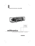
SITRANS WW200
Operating Instructions 03/2010
SITRANS
Safety Guidelines: Warning notices must be observed to ensure personal safety as well as that of
others, and to protect the product and the connected equipment. These warning notices are
accompanied by a clarification of the level of caution to be observed.
Qualified Personnel: This device/system may only be set up and operated in conjunction with this
manual. Qualified personnel are only authorized to install and operate this equipment in accordance with
established safety practices and standards.
Unit Repair and Excluded Liability:
•
•
•
•
The user is responsible for all changes and repairs made to the device by the user or the user’s
agent.
All new components are to be provided by Siemens Milltronics Process Instruments Inc.
Restrict repair to faulty components only.
Do not reuse faulty components.
Warning: Cardboard shipping package provides limited humidity and moisture protection. This product
can only function properly and safely if it is correctly transported, stored, installed, set up, operated, and
maintained.
This product is intended for use in industrial areas. Operation of this equipment in a residential area
may cause interference to several frequency based communications.
Note: Always use product in accordance with specifications.
Copyright Siemens Milltronics Process
Instruments Inc. 2010. All Rights Reserved
This document is available in bound version and in
electronic version. We encourage users to purchase
authorized bound manuals, or to view electronic
versions as designed and authored by Siemens
Milltronics Process Instruments Inc. Siemens
Milltronics Process Instruments Inc. will not be
responsible for the contents of partial or whole
reproductions of either bound or electronic versions.
Disclaimer of Liability
While we have verified the contents of this
manual for agreement with the instrumentation
described, variations remain possible. Thus we
cannot guarantee full agreement. The contents
of this manual are regularly reviewed and
corrections are included in subsequent editions.
Please check the website shown below for the
latest manual revisions.
We welcome all suggestions for improvement.
Technical data subject to change.
MILLTRONICS®is a registered trademark of Siemens Milltronics Process Instruments Inc.
Contact SMPI Technical Publications
at the following address:
Technical Publications
Siemens Milltronics Process Instruments Inc.
1954 Technology Drive, P.O. Box 4225
Peterborough, Ontario, Canada, K9J 7B1
Email: [email protected]
•
•
European Authorized Representative
Siemens AG
Industry Sector
76181 Karlsruhe
Deutschland
For a selection of Siemens Milltronics level measurement manuals, go to:
www. siemens.com/level. Choose Instructions and Manuals under the More Info list.
For a selection of Siemens Milltronics weighing manuals, go to:
www. siemens.com/weighing. Choose Support, and then Manuals / Operating Instructions.
© Siemens Milltronics Process Instruments Inc. 2010
Table of Contents
Safety ..................................................................................................................................... 2
Safety and General Precautions .........................................................................................................2
Specifications ...................................................................................................................... 3
Operation .............................................................................................................................. 5
Weighfeeders ...........................................................................................................................................5
Mechanical Installation .................................................................................................... 6
Installation ................................................................................................................................................6
Calibration ............................................................................................................................ 8
Test Load ...................................................................................................................................................8
Zero .............................................................................................................................................................8
Span ............................................................................................................................................................8
Wiring .................................................................................................................................... 9
Start Up ............................................................................................................................... 10
Shear Gate ..............................................................................................................................................10
Skirtboards ..............................................................................................................................................10
Changing the Conveyor Belt ...............................................................................................................11
Belt Tension ............................................................................................................................................11
Belt Tracking ...........................................................................................................................................12
....................................................................................................................................................................12
Telescoper Adjustment ........................................................................................................................12
Load Cell Replacement ........................................................................................................................13
Removing Old Load Cell .......................................................................................................................13
Installing New Load Cell ......................................................................................................................14
Calibration ...............................................................................................................................................15
Quick Start Up Overview .....................................................................................................................15
Troubleshooting ................................................................................................................. 16
Mechanical Troubleshooting ..............................................................................................................16
Maintenance ...................................................................................................................... 17
Preventative Maintenance .................................................................................................................17
Recommended Preventative Maintenance Schedule .................................................................17
General Maintenance ..........................................................................................................................17
Lubrication ..............................................................................................................................................18
Weighfeeder Storage Recommendations ......................................................................................18
Dimensions ........................................................................................................................ 19
i
mmmmm
Safety Notes .............................................................................................................................................1
The Manual ...............................................................................................................................................1
Table of Contents
SITRANS WW200 ................................................................................................................ 1
ii
Table of Contents
mmmmm
SITRANS WW200
SITRANS WW200 is a low- to medium- capacity weighfeeder for minor ingredient
additives.
The unique weigh system applies live load directly to two platform load cells. The
SITRANS WW200 comes with weigh bridge, speed sensor, and test weights. An
integrator is required to complete the system.
Safety Notes
Note: means important information about the product or that part of the operating
manual.
The Manual
Notes:
•
•
The SITRANS WW200 product is to be used only in the manner outlined in this
instruction manual.
This product is intended for use in industrial areas. Operation of this equipment
in a residential area may cause interference to several frequency based
communications.
This instruction manual covers the operation, installation, and maintenance of WW200.
Specific information for your Weighfeeder model is also included such as: motor, reducer,
testing documents, customer application data, spare parts.
Please refer to this manual for proper installation and operation of SITRANS WW200.
Adhering to the installation and operating procedures will ensure a quick, trouble-free
installation and allow for the maximum accuracy and reliability of your weighfeeder.
If you have any questions, comments, or suggestions about the manual contents, please
email us at [email protected].
For the complete library of Siemens manuals,
go to www. siemens.com/processautomation.
7ML19985MS01
SITRANS WW200 - OPERATING INSTRUCTIONS
Page 1
mmmmm
WARNING means that failure to observe the necessary
precautions can result in death, serious injury, and/or considerable
material damage.
Introduction
Special attention must be paid to warnings and notes highlighted from the rest of the text
by grey boxes.
Safety
Safety and General Precautions
WARNING: Always follow safe practices when working on or
around the SITRANS WW200, especially in wet environments and
when adjacent to conductive steel mounting framework.
ALWAYS STOP the belt, lock-out, and/or place a "Do Not Energize"
tag on the main disconnect before working on or around the
weighfeeder.
Note: A weighfeeder can be dangerous. Pinch points exist along the conveyor belt
line.
Safety
mmmmm
Secure the weighfeeder when:
•
•
•
•
replacing the belt
placing or removing the calibration test chain
working on or around the load cell
working on or around the speed sensor
WARNING: Whenever working near chain or belt drives, make sure
guards are in place and the equipment is safely secured. The pinch
points created by these drives can be serious.
Page 2
SITRANS WW200 - OPERATING INSTRUCTIONS
7ML19985MS01
Specifications
Accuracy
• ± 0.5%1
Operating Temperature
• -10 to +40 °C (+14 to +104 °F)
Materials
• mild steel with stainless steel, abrasive resistant contact parts optional
Load Cells
• two corrosion resistant platform type with mechanical overload protection
(aluminum or stainless steel)
• non-linearity
± 0.03%
• non-repeatability
± 0.02%
Speed Sensor
• C-flange mounted magnetic pulse generator, adapted between motor flange and
reducer input flange
• optical encoder (optional)
Framework
• precision machined, stainless or mild steel
• cantilevered design for easy belt replacement
Pulleys
• polyester carcass with polyurethane top cover and static control with vulcanised
endless finger splice for maximum weighing consistency (standard)
• variety of different belts for specific applications (optional)
1.
Accuracy subject to: On factory approved installations, the weighfeeder system’s
totalized weight will be within the specified accuracy when compared to a
known weighed material test sample. The test rate must be within the specified
range of the design capacity and held constant for the duration of the test. The
minimum material test sample must be equivalent to a sample obtained at the
test flow rate for three revolutions of the belt or at least ten minutes running
time, whichever is greater
7ML19985MS01
SITRANS WW200 - OPERATING INSTRUCTIONS
Page 3
mmmmm
Belting
Specifications
• 152 mm (6") diameter with 6 mm (¼”) rubber lagging on drive pulley for maximum
traction, 152 mm (6”) crowned tail.
Belt Tension
• screw type, telescoper module with 150 mm (6") travel (mild or stainless steel)
Belt Cleaning
• UHMW blade type with spring tensioning at head pulley
• return plow
Belt Support
• edge of flatbars eliminates material buildup
Drive
• 0.37 kW (0.5 HP) TEFC AC or DC motor with shaft mounted worm gear reducer
• larger motors available
Shipping Weight
• 280 kg (617 lbs) minimum
Approvals
Specifications
mmmmm
• for use in hazardous rated areas, consult with factory
Page 4
SITRANS WW200 - OPERATING INSTRUCTIONS
7ML19985MS01
Operation
Weighfeeders
Weighfeeders weigh bulk material while it is conveyed. An accurate rate of flow and
totalized weight measurement is received without interrupting the flow of material in
process. A weighfeeder can also control the rate of flow of the conveyed product.
In-motion weighing requires accurate transmission of the product load to strain gauge
load cells. The resulting voltage signal corresponding to weight is transmitted to the
integrator and becomes one of the two inputs required for integration.
Unlike static weighing, in-motion weighing integration requires a second input: a pulse
signal proportional to the speed of the conveyor belt. Each belt speed sensor pulse
represents a fixed distance of the travel.
Since the force measured by the load cell is represented as weight per unit length, it can
be multiplied by the distance of belt travel (one speed sensor pulse) to provide product
weight for that segment of the belt (lbs/ft x ft = lbs, or kg/m x m = kg).
Adding the samples provides total throughput weight of product across the scale. With
proper scaling and calibration, the total weight can be displayed in kilograms, pounds,
short tons, long tons, metric tons, or other appropriate units.
Open
Enclosed
SITRANS WW200 - OPERATING INSTRUCTIONS
Page 5
mmmmm
Operation
7ML19985MS01
Installation
mmmmm
Mechanical Installation
Perform a thorough and systematic inspection of containers immediately upon receipt of
your Siemens weighfeeder. The containers are packed to separate each item and provide
protection during shipping.
Note: Do not remove equipment from shipping crates or boxes until you check for
possible shipping damage. Contact the carrier immediately if damage is noted.
Your weighfeeder has been designed, assembled, and factory tested for your specific
application.
Notes:
•
•
•
•
Refer to the mechanical drawings sent with this manual prior to commencing with
installation.
Do NOT remove the tagged load cell shipping bolt(s) until the installation is
complete to prevent load cell damage.
Do NOT weld on or near the weighfeeder while the load cell is connected to the
electronic integrator. Damage to the integrator may result if the load cell is not
disconnected from the integrator.
Follow a scheduled, preventative maintenance program to ensure optimum
performance and long equipment life.
Installation
Note: Only qualified personnel are authorized to install and operate this equipment.
Installation shall be in accordance with local regulations, standards and established
safety practices. Read and understand the instructions before installing, operating or
maintaining the equipment.
1.
2.
3.
4.
Align the in-feed section of the weighfeeder with the discharge of the feed device.
Prevent twisting or misalignment that could induce stress on the weighing section.
Securely fasten the unit to a rigid, level structure. Use a level for verification and
shim as necessary. Prevent any twisting of the frame that may affect weighfeeder
performance.
Construct the necessary support framework to provide a sturdy, rigid base. Vibration
isolators are recommended if the location is subject to moderate or heavy vibration.
Inlet and discharge will not support load.
Note: If your system has a permanently lubricated gear motor, then disregard Step 5.
5.
6.
7.
Page 6
Check the gear reducer oil level. See the gear reducer information for further details
on maintenance.
Flexible in-feed connections are REQUIRED for all applications. Flexible discharge
connections are also recommended.
Connect the proper electric supply to the motor and/or motor controller, following
the interwiring diagram supplied with this manual. The AC or DC motor controller (if
SITRANS WW200 - OPERATING INSTRUCTIONS
7ML19985MS01
minimize the possibility of load cell damage resulting from incidental overload.
9.
Before starting the machine, make a final check to see that the conveyor belt is free
of all tools and foreign objects.
7ML19985MS01
SITRANS WW200 - OPERATING INSTRUCTIONS
Page 7
mmmmm
Note: DO NOT loosen or tighten the overload bolt—it has been factory set to
Installation
8.
present) must be grounded to minimize noise to the electronic integrator. Refer to
the applicable wiring diagram to make all electrical connections between the
electronic integrator and the weighfeeder.
Remove only the tagged shipping bolt that is attached to the load cell. This bolt
supports the weighbridge during transport and installation.
Calibration
After SITRANS WW200 has been properly installed, calibration of the weighing system
must be done in conjunction with the integrator. Refer to the integrator instruction
manual for programming and calibration. The calibration is initially done using the
supplied test load. Material tests are recommended to achieve maximum accuracy.
Calibration
mmmmm
Test Load
The test load value for your SITRANS WW200 is given on the accompanying test sheet.
The value is already entered into the dedicated programming parameter of the integrator,
in kilograms per meter or pounds per foot.
Zero
Perform the zero calibration as described in the Calibration section of the integrator
manual.
Span
The test load used in the calibration procedure is a set of factory sized and supplied test
weights (2).
Perform the span calibration as described in the Calibration section of the integrator
instruction manual.
After the span calibration has been completed, remove the test load and store it.
Page 8
SITRANS WW200 - OPERATING INSTRUCTIONS
7ML19985MS01
Wiring
load cell
‘B’
load cell
‘A’
Note:
aluminum/
nickelplated
shown for
reference
R R B B
E E L L
D D K K
‘A’ ‘B’ ‘A’ ‘B’
W
H
T
‘B’
G
R
N
‘B’
S
I
G
+
S
I
G
S
I
G
+
S
I
G
A
A
B
B
junction box
S
H
I
E
L
D
to integrator
Aluminum/Nickelplated
Stainless Steel
RED
GREEN
TB 2 +Sense
TB 3 -Sense
TB 4 -Excitation
BLACK
BLACK
TB 5 +Load Cell A
GREEN
WHITE
TB 6 -Load Cell A
WHITE
BLACK/RED
TB 7 +Load Cell B
GREEN
WHITE
TB 8 -Load Cell B
WHITE
BLACK/RED
YELLOW
YELLOW/CLEAR
SIEMENS
MILLTRONICS LC/SP JUNCTION BOX
TB 1 +Excitation
TB 9 SHIELD
TB 10 Speed Excitation
RED
RED
TB 11 Speed Common
BLACK
BLACK
TB 12 Speed Signal
WHITE
WHITE
7ML19985MS01
SITRANS WW200 - OPERATING INSTRUCTIONS
Page 9
mmmmm
G
R
N
‘A’
Wiring
E
X
C
+
E
X
C
W
H
T
‘A’
S S
H H
I I
E E
L L
D D
‘A’ ‘B’
Start Up
Your weighfeeder has been factory run-in for a minimum of four hours; it should require
little adjustment. However, periodic inspections of the belt tracking are recommended.
Start the belt and observe rotation.
WARNING: Turn off and lock out all power sources before
correcting rotation. On DC motors, reverse the armature wires. On
AC motors, reverse 2 of the 3 motor wires.
Start the belt again and observe the machine as it is running. If the belt is not tracking
correctly or is tracking off center, see Belt Tracking on page 12.
Shear Gate
The shear gate on the inlet of the weighfeeder needs to be set to allow the maximum
feedrate capacity requested by the customer. Consult your Siemens Milltronics
representative if feed rate changes are required.
Skirtboards
The skirtboards have also been factory set to proper specifications. Note that near the
inlet, the skirtboards are very close to the belt. However, toward the discharge end of the
weighfeeder, the skirtboards are 1/8" to 3/16" higher off the belt. This relieving effect
minimizes the possibility of material becoming lodged between the skirtboard and the
belt.
Periodic adjustments of the skirtboards should not be necessary but if adjustment is
required, set the skirtboards at the heights described above.
skirtboard
Start Up
mmmmm
Your system may have been supplied with soft PVC seal strips if the product being
conveyed is a fine powder. Position the seal strips on the skirtboards as shown.
seal strip
do not force seal
strip against belt
pulley
belt
Page 10
SITRANS WW200 - OPERATING INSTRUCTIONS
7ML19985MS01
Changing the Conveyor Belt
1.
Open and remove the access and non-access side covers (omit this step on open
construction models).
2.
Mark the position of the telescopers for reference. This will be handy when you reinstall the belt. Loosen the telescopers to remove tension from the belt.
3.
At the discharge end of the conveyor, find the belt scraper spring tensioner. Unhook
the spring on both sides of the belt scraper arm and let the belt scraper swing down
away from the belt.
Note: Skirtboard removal or adjustment is not normally necessary to perform belt
removal or installation, nor is it recommended.
4.
Remove support posts on the access site, remove rail end extensions.
5.
From the access side of the feeder at the discharge end, grab the edge of the belt on
the top and bottom. Gently pull the belt over the side rail, making sure that the
leading edge of the belt does not catch on the side rail.
6.
Now repeat Step 4 on the inlet end of the feeder. Again, be careful not to cut or
scrape the belt on the side rail.
7.
When both ends have been pulled to the outside of the side rail, you may grab the
belt in the middle and slowly remove the belt. As the belt is removed, mark the
direction the belt was rotating. This mark will allow you to re-install the belt in the
same direction. Take care when storing the belt to prevent kinks or other damage.
8.
With the belt removed, inspect the feeder for material build up, lodged particles, and
signs of wear, paying close attention to the weigh section area. Take care when
cleaning the weigh section area, as 15 lbs. (or less) pressure placed on the
weighbridge could cause loadcell damage.
9.
Reverse steps 1-7 to re-install the same belt.
The ideal belt tension for any weighfeeder is just enough tension to prevent the belt from
slipping on the drive pulley. The tension minimizes the effect of the belt on weighing
accuracy. Often, the sole cause of an inaccurate weighfeeder is excessive belt tension.
Specific belt tension cannot be given because the weighfeeder could be mounted in
various applications. As a general guideline, the bottom of the belt should droop 1-2
inches over the length of the weighfeeder. This is only an approximate specification, as
your application may require more or less tension due to varying belt loading and other
operating characteristics.
7ML19985MS01
SITRANS WW200 - OPERATING INSTRUCTIONS
Page 11
mmmmm
Belt Tension
Start Up
Note: On a new replacement belt, there may be an arrow printed on the underside of
the belt. This arrow indicates what direction the belt should rotate when it is installed.
If there is no arrow, rotation of the belt may be in either direction. Whenever a new
belt is installed, perform the belt tracking procedure (see Belt Tracking on page 12).
Belt Tracking
1.
Before attempting to track the belt, be sure:
• belt scraper and belt tension counterweights are in place
• belt tension is near guidelines suggested on page 11
• feeder is level and true
• installation has not warped or twisted the frame
• head and tail pulley are square
• plow is contacting underside
Turn on the feeder and observe its tracking line on the head and tail pulleys.
If the belt is drifting toward one side of the feeder, then adjust the telescoper on
either side of the machine (see below).
Adjust belt tracking rollers as necessary.
2.
3.
Telescoper Adjustment
1.
Determine which side of the weighfeeder you want to adjust. Compressing the
telescoper on one side will cause the belt to drift toward that side of the
weighfeeder. Conversely, extending the telescoper will cause the belt to drift away
from that side of the weighfeeder.
Loosen the jam nut.
2.
3.
Turn the adjusting screw in the desired direction. Often, only a small amount of
adjustment (1 turn or less) will be required.
4.
Observe the results of the adjustment and then readjust, if necessary.
Steps 2 and three 3 need to be repeated to obtain perfect belt tracking.
Note: As you extend or compress the telescoper, you may be changing the belt
tension. If belt tension has increased (or decreased) considerably while attempting to
track the belt, then compress (or extend) both telescopers and complete the belt
tracking process again. To avoid this problem, extend one telescoper while
compressing the other to obtain proper belt tracking.
Start Up
mmmmm
5.
Page 12
Re-tighten the jam nut located on the telescoper to maintain the new telescoper
position after completing the tracking procedure.
SITRANS WW200 - OPERATING INSTRUCTIONS
7ML19985MS01
6.
If you are having problems tracking the belt, consult Siemens Milltronics. Common
causes of belt tracking problems are: uneven or improperly distributed product
loading, twisted frame, or product buildup on head or tail pulleys.
jam nut
adjusting screw
side rail
driven shaft
Load Cell Replacement
WARNING: ALWAYS STOP the belt, lock-out, and/or place a "Do
Not Energize" tag on the main disconnect before working on or
around the weighfeeder.
If a load cell on SITRANS WW200 has been damaged and is not functioning or if you are
changing the capacity, you will need to replace one or all load cells.
Note: Please read and understand all of the instructions before proceeding with the
replacement. Contact your Siemens Milltronics representative for assistance if you
have any questions or problems.
Removing Old Load Cell
2.
Disconnect the load cell being replaced from the junction box. Verify that the load
cell is connected according to the interwiring diagram supplied with this manual.
Disconnect the load cell from the load cell junction box. Free the load cell cable from
the feeder so it is hanging free from the load cell.
7ML19985MS01
SITRANS WW200 - OPERATING INSTRUCTIONS
Page 13
mmmmm
Confirm the new replacement load cell is correct and functional. Using a digital volt
meter or ohm meter, verify that the resistance of the new load cell matches the
resistance printed on the specification sheet that comes with the load cell. If the
resistances do not match, the load cell may be damaged. Consult your Siemens
Milltronics representative.
Start Up
1.
3.
Install the shipping screw (tagged) through the bottom load cell mount and into the
load cell. Tighten the shipping screw until the load cell bottoms out on the overload
screw.
weigh deck
belt
top load cell mount
overload screw
shipping screw
load cell
bottom load cell mount
4.
Support the scale deck and remove the two top load cell mount bolts. Be careful not
to move the deck as it is still attached to the load cell on the other side of the
weighfeeder.
5.
Remove the two bottom load cell mount bolts. The load cell is now held in place only
by the shipping bolt.
6.
Support the scale deck with a block of wood or have an assistant hold it. Remove
the shipping screw and slide the load cell off the feeder.
Start Up
mmmmm
Installing New Load Cell
1.
Slide the new load cell into position and carefully screw in the load cell shipping
screw. Do not overtighten the screw.
2.
Install the two bottom load cell mount bolts. Tighten them by hand. Now re-tighten
the shipping bolt so the load cell is resting against the overload stop.
3.
Install the two top load cell mount bolts. Tighten them by hand.
4.
Start with the bottom load cell mounting bolts and tighten them to 200 in-lb torque.
Now tighten the two top load cell mounting bolts to 200 in-lb torque.
5.
Remove the shipping screw.
6.
Route the load cell cable to the junction box and connect the load cell according to
the supplied interwiring diagram. Repeat for other load cells if necessary.
7.
Perform a load cell balancing procedure as described in the integrator instruction
manual.
Page 14
SITRANS WW200 - OPERATING INSTRUCTIONS
7ML19985MS01
Calibration
1.
Power up the integrator and using the appropriate integrator menu, verify that the
new load cell(s) are operating correctly.
2.
Zero calibrate the unit. using the integrator manual for reference. Record zero
calibration procedure results.
3.
Span calibrate the unit using the integrator manual for reference. Record span
calibration procedure results.
4.
Re-check zero calibration. Run another zero calibration and record the results.
Verify that the zero repeated to the same value recorded in step 2.
5.
Confirm calibration with material test as described in the integrator manual, if
possible, before placing the feeder back in operation.
Quick Start Up Overview
1.
2.
3.
4.
Verify that the weighfeeder is installed properly as described in the Mechanical
Installation section on page 6. Verify that the belt is tracking and the shear gate (if
used) is properly set.
Verify that the weighfeeder, integrator/controller, and variable speed drive (AC or DC,
if present) are all properly wired.
Verify that the data on the design data sheet included with this manual is correct
and modify if required.
Refer to the supplied integrator/controller manual for calibration and configuration
information.
SITRANS WW200 - OPERATING INSTRUCTIONS
Page 15
mmmmm
Start Up
7ML19985MS01
Troubleshooting
Mechanical Troubleshooting
Review mechanical installation procedures and perform a thorough visual inspection to
be sure the operating error is caused by a mechanical problem. Then review and check
the common problems listed below.
Note: If you have difficulty determining the cause of the problem, contact the Service
Department at Siemens Milltronics. Be sure to have the Model Number and Serial
Number of your system and all of the calibration and setup parameters available
before calling.
Zero Drift, non-repeatability, or non-linearity
Check for these following conditions:
Troubleshooting
mmmmm
• weigh deck alignment. Verify weigh deck alignment is as accurate as possible.
Improper alignment is the most common mechanical problem affecting scale
accuracy. Contact Siemens Milltronics if you find a problem here (should be 1/32”
aligned with slider bars approach and retreat).
• material buildup on weigh section or pulleys, or between the weigh deck and
feeder frame.
• belt mis-tracking.
• belt too tight.
• load cell bolts loose.
• speed sensor pulley slippage.
• load cell shipping bolt (tagged) never removed.
• head or tail pulley too high or low, relative to idler/slider bed alignment.The head
and tail pulleys should be at least 1/8" lower than the approach and retreat slider
beds.
Page 16
SITRANS WW200 - OPERATING INSTRUCTIONS
7ML19985MS01
Maintenance
The maintenance schedule below is recommended to maintain top performance and
accuracy of the system. Weighfeeders mounted in severe weather or dusty conditions
may require a more rigorous maintenance schedule.
Make sure the weigh idler is aligned with the approach and retreat sections for accurate
weighing. Periodic measurement to verify alignment is recommended.
Recommended Preventative Maintenance
Schedule
Item
Required Maintenance
Frequency
Comments
Weigh
Section
Blow or brush off any material
building up
Weekly
More frequently in dirty
environments
Belt Tracking
Visually inspect to assure the
conveyor belt remains trained
Daily
-------
Calibration
Verify belt
zero
Verify belt zero
Daily or at
least once a
week
See Calibration section of
Integrator Manual
Calibration
span check
Use Calibration Weights
Montly
See Calibration section of
Integrator Manual
Bearings
Inspect and lubricate as required
Electric
motor (DC)
Check brushes
Every 10,000
hours
Inspect and replace as
necessary
Electric
motor (AC)
None
None
Bearings are sealed and
permanently lubricated
Gear reducer
Check oil level/Replace oil
Monthly/
Every 2500
hours
Refer to manufacturer
maintenance manual/See note
on next page
Every 10,000 Use #3 NLGI grade lithium base
hours
grease
General Maintenance
The equipment should be cleaned periodically to maintain accuracy. Any excess
accumulation of product should be removed to minimize potential damage to the
mechanical components and scale accuracy.
Abrasions, cuts, or ragged edges on the belt will create performance problems. Replace
the belt if it becomes ragged or torn.
7ML19985MS01
SITRANS WW200 - OPERATING INSTRUCTIONS
Page 17
mmmmm
Preventative Maintenance
Maintenance
WARNING: ALWAYS STOP the belt, lock-out, and/or place a "Do
Not Energize" tag on the main disconnect before working on or
around the weighfeeder.
Maintenance
mmmmm
Lubrication
All head and tail pulley bearings are pre-greased at the factory. These bearings should be
field greased periodically. The frequency of lubrication may vary due to specific operating
conditions. Some dry, dusty applications may warrant weekly greasing, while other less
harsh applications may need greasing only once or twice a year. In no case, however,
should more than 10,000 hours elapse between re-greasing.
If there is a gear reducer supplied with your weighfeeder, it has an initial break-in period.
After the first 250 hours of operation, the gear box(es) should be drained and refilled to
the proper level(s). Subsequent oil changes should be done every 2500 hours. See the
gear reducer manual provided for further details.
If there is a gear motor (motor and reducer all in one housing) supplied with your unit, it is
permanently lubricated. No lubrication is necessary.
Weighfeeder Storage Recommendations
If a weighfeeder will be stored for a period of three months or more, follow the guidelines
below:
Load Cell Care
The load cell shipping bolts should be installed whenever the feeder is moved. It is a good
idea to install these shipping bolts during the storage period as an extra safety measure.
Do not forget to remove the shipping bolts upon re-installation.
Gear Reducer/Gear Motor
Uncouple the gear reducer from the feeder drive shaft and the motor. After the reducer is
removed, liberally grease all shaft surfaces with an appropriate lubricant to help with
reassembly.
In addition, completely fill the gear reducer with an appropriate gear oil to prevent the
formation of any oxidation. When the equipment is re-installed, completely drain this gear
oil and refill the reducer to the appropriate level.
Electrical
To prevent oxidation, place a desiccant or moisture removal material in all electrical
junction boxes component cabinets. This includes the load cell junction box, the
integrator cabinet, and the motor speed controller enclosure (if present).
Lubrication
Grease all greasable points.
Belt Care
Reduce belt tension to a minimum to prevent belt damage and re-adjust belt tension at
re-installation.
Note: Do NOT store the weighfeeder in direct sunlight, as this will cause premature
breakdown of the belt.
Page 18
SITRANS WW200 - OPERATING INSTRUCTIONS
7ML19985MS01
Dimensions
Open Unit
A (nominal)
belt width
“A”
inlet
1321 mm
(52”)
discharge
724 mm
(28.5”)
229 mm
(9”)
698 mm
(27.5”)
“A”
Open Unit
Belt Width
305 mm (12”)
457 mm (18”)
610 mm (24”)
762 mm (30”)
914 mm (36”)
1067 mm (42”)
1219 mm (48”)
7ML19985MS01
A
660 mm (26”)
813 mm (32”)
965 mm (38”)
1118 mm (44”)
1270 mm (50”)
1422 mm (56”)
1575 mm (62”)
B
257 mm (10.14”)
333 mm (13.13”)
410 mm (16.13”)
486 mm (19.13”)
562 mm (22.13”)
635 mm (25”)
711 mm (28”)
SITRANS WW200 - OPERATING INSTRUCTIONS
C
425 mm (16.75”)
578 mm (22.75”)
730 mm (28.75”)
883 mm (34.75”)
1035 mm (40.75”)
1187 mm (46.75”)
1340 mm (52.75”)
Page 19
mmmmm
Dimensions
B
C
Enclosed Unit
view A-A
A (nominal)
B
Dimensions
mmmmm
belt width
C
B/2
C/2
“A”
inlet
425 mm
(16.75”)
1975 mm (77.75”)
1321 mm (52”)
discharge
908 mm
(35.75”)
146 mm
(5.75”)
95 mm (3.75”)
425 mm
(16.75”)
1016 mm
(40”)
“A”
Enclosed Unit
Belt Width
305 mm (12”)
457 mm (18”)
610 mm (24”)
762 mm (30”)
914 mm (36”)
1067 mm (42”)
1219 mm (48”)
Page 20
A
889 mm (35.38”)
1051 mm (41.38”)
1203 mm (47.38”)
1356 mm (53.38”)
1508 mm (59.38”)
1661 mm (65.38”)
1813 mm (71.38”)
B
686 mm (27”)
838 mm (33”)
991 mm (39”)
1143 mm (45”)
1295 mm (51”)
1448 mm (57”)
1600 mm (63”)
SITRANS WW200 - OPERATING INSTRUCTIONS
C
711 mm (28”)
864 mm (34”)
1016 mm (40”)
1168 mm (46”)
1321 mm (52”)
1473 mm (58”)
1626 mm (64”)
7ML19985MS01
Notes.fm Page 1 Thursday, October 11, 2001 8:48 AM
Notes
Notes.fm Page 1 Thursday, October 11, 2001 8:48 AM
Notes
IQ300IX.fm Page 5 Tuesday, October 2, 2001 1:43 PM
www.siemens.com/processautomation
For more information
www.siemens.com/level
www.siemens.com/continuous-weighing
Siemens Milltronics Process Instruments Inc.
Industry Automation (IA)
1954 Technology Drive
P.O. Box 4225
Peterborough, ON
Canada K9J 7B1
Subject to change without prior notice
7ML19985MS01 Rev. 1.0
© Siemens Milltronics Process Instruments Inc. 2010
email: [email protected]
www.siemens.com/processautomation
*7ml19985MS01*
Printed in Canada