1
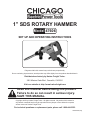
1” SDS ROTARY HAMMER
Model 47606
Set up And Operating Instructions
Diagrams within this manual may not be drawn proportionally.
Due to continuing improvements, actual product may differ slightly from the product described herein.
Distributed exclusively by Harbor Freight Tools®.
3491 Mission Oaks Blvd., Camarillo, CA 93011
Visit our website at: http://www.harborfreight.com
Read this material before using this product.
Failure to do so can result in serious injury.
Save this manual.
Copyright© 2002 by Harbor Freight Tools®. All rights reserved. No portion of this manual or
any artwork contained herein may be reproduced in any shape or form without the express
written consent of Harbor Freight Tools.
For technical questions or replacement parts, please call 1-800-444-3353.
Revised 07c, 07j
Specifications
Chuck Capacity
1 Inch
Power
120 V, 60 Hz, 1.13 HP, 850 Watts
Amperage
6.8 Peak Amps, 4.6 Working Amps
RPM
900
Blows per minute
3,200
Accessories: Break Point (Bull) Bit, Flat Head Chisel, Depth Rod, Lubricant,
Masonry Drill Bits (10mm, 9/16”, 7/8”), Extra Brushes, Blowmold Case
Save This Manual
You will need the manual for the safety warnings and precautions, assembly instructions, operating
and maintenance procedures, parts list and diagram. Keep your invoice with this manual. Write
the invoice number on the inside of the front cover. Keep the manual and invoice in a safe and
dry place for future reference.
Safety Warnings and Precautions
WARNING: When using tool, basic safety precautions should always be followed to reduce
the risk of personal injury and damage to equipment.
Read all instructions before using this tool!
1.
Keep work area clean. Cluttered areas invite injuries.
2.
Observe work area conditions. Do not use machines or power tools in damp or wet locations.
Don’t expose to rain. Keep work area well lighted. Do not use electrically powered tools in the
presence of flammable gases or liquids.
3.
Keep children away. Children must never be allowed in the work area. Do not let them handle
machines, tools, or extension cords.
4.
Store idle equipment. When not in use, tools must be stored in a dry location to inhibit rust.
Always lock up tools and keep out of reach of children.
5.
Use the right tool for the job. Do not attempt to force a small tool or attachment to do the
work of a larger industrial tool. There are certain applications for which this tool was designed.
It will do the job better and more safely at the rate for which it was intended. Do not modify this
tool and do not use this tool for a purpose for which it was not intended.
6.
Dress properly. Do not wear loose clothing or jewelry as they can be caught in moving parts.
Protective, electrically nonconductive clothes and nonskid footwear are recommended when
working. Wear restrictive hair covering to contain long hair.
7.
Use eye, face and ear protection. Always wear ANSI approved impact safety goggles. Wear
a full face shield if you are producing metal filings or wood chips. Wear an ANSI approved dust
mask or respirator when working around metal, wood, and chemical dusts and mists.
8.
Do not overreach. Keep proper footing and balance at all times. Do not reach over or across
running machines.
9.
Maintain tools with care. Keep tools sharp and clean for better and safer performance. Follow
instructions for lubricating and changing accessories. Inspect tool cords periodically and, if
SKU 47606
For technical questions, please call 1-800-444-3353.
REV 03d; 05k
Page damaged, have them repaired by an authorized technician. The handles must be kept clean,
dry, and free from oil and grease at all times.
10.
Disconnect power. Unplug tool when not in use.
11.
Remove adjusting keys and wrenches. Check that keys and adjusting wrenches are
removed from the tool or machine work surface before plugging it in.
12.
Avoid unintentional starting. Be sure the switch is in the Off position when not in use and
before plugging in. Do not carry any tool with your finger on the switch, whether it is plugged in
or not.
13.
The Rotary Hammer must be switched off and unplugged before changing the Knob
setting. Attempting to change the Knob setting while the motor is engaged will result in abrupt
bit rotation and can cause serious personal injury and/or property damage.
14.
Stay alert. Watch what you are doing, use common sense. Do not operate any tool when you
are tired.
15.
Take caution as some woods contain preservatives such as copper chromium arsenate
(CCA) which can be toxic. When drilling or chiseling these materials extra care should be
taken to avoid inhalation and minimize skin contact.
16.
Check for damaged parts. Before using any tool, any part that appears damaged should be
carefully checked to determine that it will operate properly and perform its intended function.
Check for alignment and binding of moving parts; any broken parts or mounting fixtures; and
any other condition that may affect proper operation. Any part that is damaged should be
properly repaired or replaced by a qualified technician. Do not use the tool if any switch does
not turn On and Off properly.
17.
Guard against electric shock. Prevent body contact with grounded surfaces such as pipes,
radiators, ranges, and refrigerator enclosures.
18.
Replacement parts and accessories. When servicing, use only identical replacement parts.
Use of any other parts will void the warranty. Only use accessories intended for use with this
tool. Approved accessories are available from Harbor Freight Tools.
19.
Do not operate tool if under the influence of alcohol or drugs. Read warning labels on
prescriptions to determine if your judgment or reflexes are impaired while taking drugs. If there
is any doubt, do not operate the tool.
20.
Use proper size and type extension cord. If an extension cord is required, it must be of the
proper size and type to supply the correct current to the tool without heating up. Otherwise,
the extension cord could melt and catch fire, or cause electrical damage to the tool. This tool
requires use of an extension cord of 0 to 10 amps capability (up to 50 feet), with wire size rated
at 18 AWG. Longer extension cords require larger size wire. If you are using the tool outdoors,
use an extension cord rated for outdoor use (signified by “WA” on the jacket).
21.
Maintenance. For your safety, maintenance should be performed regularly by a qualified
technician.
22.
WARNING: Some dust created by power sanding, sawing, grinding, drilling, and other
construction activities, contain chemicals known [to the State of California] to cause cancer, birth
defects or other reproductive harm. Some examples of these chemicals are:
SKU 47606
For technical questions, please call 1-800-444-3353.
REV 07c
Page - Lead from lead-based paints
- Crystalline silica from bricks and cement or other masonry products
- Arsenic and chromium from chemically treated lumber
Your risk from these exposures varies, depending on how often you do this type of work.
To reduce your exposure to these chemicals: work in a well ventilated area, and work with
approved safety equipment, such as those dust masks that are specially designed to filter out
microscopic particles. (California Health & Safety Code § 25249.5, et seq.)
23.
The warnings, cautions, and instructions discussed in this instruction manual cannot cover all
possible conditions and situations that may occur. It must be understood by the operator that
common sense and caution are factors which cannot be built into this product, but must be
supplied by the operator.
Note Performance of this tool (if powered by line voltage) may vary depending on variations in local
line voltage. Extension cord usage may also affect tool performance.
Unpacking
When unpacking, check to make sure the parts listed on page 8 are included. If any parts are
missing or broken, please call Harbor Freight Tools at the number on the cover of this manual as soon
as possible.
Vibration Hazard
This tool vibrates during use. Repeated or long-term exposure to vibration may cause
temporary or permanent physical injury, particularly to the hands, arms and shoulders. To
reduce the risk of vibration-related injury:
1.
Anyone using vibrating tools regularly or for an extended period should first be examined by
a doctor and then have regular medical check-ups to ensure medical problems are not being
caused or worsened from use. Pregnant women or people who have impaired blood circulation
to the hand, past hand injuries, nervous system disorders, diabetes, or Raynaud’s Disease
should not use this tool. If you feel any medical or physical symptoms related to vibration (such
as tingling, numbness, and white or blue fingers), seek medical advice as soon as possible.
2.
Do not smoke during use. Nicotine reduces the blood supply to the hands and fingers,
increasing the risk of vibration-related injury.
3.
Wear suitable gloves to reduce the vibration effects on the user.
4.
Use tools with the lowest vibration when there is a choice between different processes.
5.
Include vibration-free periods each day of work.
6.
To reduce vibration, maintain the tool as explained in this manual. If any abnormal vibration
occurs, stop use immediately.
REV 07j
SKU 47606
For technical questions, please call 1-800-444-3353.
Page Assembly
Refer to Figure 1.
1.
Fit the Handle Band (508) over the front of the housing above the Bit Sleeve and screw
the Handle (506) clockwise to secure. At this point do not fully tighten.
2.
Rotate the Handle (506) around the tool until it rests on a flat spot on the housing, on the
side you prefer.
Note: The Drill Stop (504) is used as a guide when doing repetitive drilling (not chiseling) at
the same depth.
3.
With the Handle (505) still loose, insert the Drill Stop (504) into the hole at the Handle
base. Fully tighten the Handle (505) clockwise. If you wish to reposition the Handle (505)
or the Drill Stop (504), loosen the Handle (505) by turning it counterclockwise.
FIGURE 1
Handle Band (508)
Bit Sleeve
Handle (505)
Drill Stop (504)
REV 07j
SKU 47606
For technical questions, please call 1-800-444-3353.
Page Inserting and removing bits.
1.
Make sure the Rotary Hammer is not plugged in.
2.
To insert a bit, pull back and retract the Bit Sleeve (see FIGURE 2) and insert the bit. Slide
the two notches on the bit into the notched receptacle and then release the Bit Sleeve. Put
on gloves and then tug on the bit forcefully, making sure it is in the Bit Sleeve firmly.
3.
When removing a bit, make sure the bit has had a chance to cool. Wear gloves and grip
the bit with one hand, and pull back on the Bit Sleeve, retracting it away from the bit. Pull
out the bit.
Note For safe, optimal performance, keeps bits and chisels properly sharpened. Never use a
dull, cracked, or chipped bit.
Bit Sleeve
Note: Break Point (Bull) Bits and cold
chisels are to be used when the Selector
Switch is in the hammering position only.
Using these bits/chisels with the Selector
Switch in the hammer/drill position will
result in unexpected tool performance.
FIGURE 2
Switch (86)
Knob (701)
Main Handle (89)
FIGURE 3
Bit Sleeve
Bit
Handle
(505)
Drill Stop (504)
Brush Cap (70)
SKU 47606
For technical questions, please call 1-800-444-3353.
REV 07c; 07j
Page Operation
Note: Make sure unit is not plugged in.
FIGURE 4
Note: If you wish, you may attach a Dust Cap for overhead
drilling applications. To do so, after you install a bit,
before you tighten the Bit Sleeve, slide the Dust Cap Curved end
over the bit and adjust the Drill Stop so that the curve on of Drill Stop
the end of the Drill Stop secures the Dust Cap. Tighten
the Handle. See FIGURE 4.
Dust
Cap
Note: Do not plug in the Rotary Hammer until the bit is loaded, the
Drill Stop is set, and the Knob selection is complete ( See Below).
1.
Following the method on page 4, number 3, under assembly,
adjust the Drill Stop to the desired length.
Note: The Drill Stop will only work when the Handle is on either side or the top of the Rotary
Hammer. The body of the Hammer will interfere with the Drill Stop if the Handle is positioned
on the bottom of the Hammer.
Warning: When setting the Knob, the Rotary Hammer must be switched off and be
unplugged. Attempting to change the Knob setting while the motor is engaged will
result in abrupt bit rotation and can cause serious personal injury and/or property
damage. See setting the Knob below.
2.
Set the Knob to either hammer/drill or hammer. See FIGURE 3 on page 5.
Hammer Setting: To hammer, turn the Knob so the “T” setting is lined up with the mark
on the housing.
Hammer/Drilling: To hammer/drill, set the Knob so the “IT” setting is lined up with the mark
on the housing.
Note: When setting the Knob make sure it positively clicks into the desired position. If
Knob does not click into place, it could slip out of position resulting in unexpected
tool performance.
3.
Install the desired bit or chisel. Only when hammer/drilling use the Drill Stop.
4.
If hammer/drilling, make sure the Drill Stop and Dust Cap, if needed, are installed
properly.
5.
The Handle should be rotated to the proper position for the application.
6.
While keeping you finger off of the Switch, plug in the unit.
7.
When you are ready to begin, make sure you have a firm grip on both the Main Handle
and the Handle. Always operate the Rotary Hammer with both hands, holding it securely.
The Rotary Hammer puts out extreme torque and will kick back and act with great force.
8.
Turn on the Switch and allow the Rotary Hammer to run without a load for approximately
one minute as the unit self-lubricates. Release the Switch, stopping the Hammer. Position
the chisel or bit on the workpiece and start the Hammer again.
9.
After using the Rotary Hammer, release the Switch to turn off the unit.
SKU 47606
For technical questions, please call 1-800-444-3353.
REV 03d, 07c
Page Troubleshooting and Maintenance
Note: Other than changing or cleaning the carbon brushes, all internal repairs should be done
by a qualified service technician.
Problem
Cause
Disrupted power
Poor switch contact
Armature or field coil burnt
Broken Stator Coil
Worn carbon brushes
Action
Motor doesn’t rotate when switched
on.
1.
2.
3.
4.
5.
Abnormal motor noise, rotates slowly,
does not rotate
Overload due to excessive drilling
depth or pressure
Reduce drill depth or
pressure/decrease force
Partial short circuit
Short circuit or open circuit armature
Repair or change armature
Low main voltage
Main power voltage too low
Adjust main power voltage
Overheated gearbox
1.
2.
3.
4.
1. Reduce load, sharpen or
replace bit
2. Dry coils
3. Repair/change armature
4. Adjust voltage
Sparking
1. Short circuit or break at armature
2. Surface of armature dirty or rough
Overload, dull bit
Damp coils
Incorrect fitting
Decrease in voltage
1.
2.
3.
4.
5.
Check Power Supply
Repair switch
Change coil
Replace Stator coil
Replace carbon brushes
1. Repair armature
2. Clean armature
Note: Rotary Hammer must be unplugged before performing service and maintenance.
General maintenance:
1. Clean the work surface with a dry brush or clean cloth. Keep moving parts lightly greased.
Always keep motor and vent areas free of dust and debris.
2. Grease the tool after 50 working hours, or more frequently with increased use.
3. Remove drill bits or chisels for storage.
Changing Carbon Brushes:
1. Using a screwdriver, remove the Brush Cap (70). See FIGURE 3 on page 5.
2. Be careful, the Brush Holder (68) may spring out. If it does not spring out easily, gently
use the tip of the screwdriver to remove it. Examine the Brush (69); the surface should
be smooth and clean. If scratch marks appear, or it is broken, replace immediately with an
approved replacement brush from Harbor Freight Tools.
3. If the Brush (69) isn’t damaged, but only dirty, clean it off with a pencil eraser. Gently rub
it until the dirt is removed. Remove the eraser dust from the Brush (69) when you are
through cleaning it.
4. Gently reinstall the Brush (69) into the Brush Holder (68) and screw the Brush Cap (70)
back on the unit and tighten.
SKU 47606
For technical questions, please call 1-800-444-3353.
Page Parts List
Part
Description
Part
Description
Part
Description
1
O-ring
35
Spring
302
Switch Handle
2
Steel Ball
36
Label
71*
Air Baffle
3
Cylinder
37
Small Cone Gear
72*
Stator
4
Flat Pin
38
Oil Seal
74*
Motor Casing
5
Striker
39
Bearing
75*
Bolt
6
O-ring
40
Washer
76*
Bottom Cap
706
Spring
41
Pull Board
77*
Tap Bolt
Cone Gear
42
Clutch Washer
78
Tap Bolt
7D
Steel Retaining Ring
43
Second Gear
79
Handle Cap
511
Oil Bearing
44
Dish Form Spring
80
Handle Buff
8
Piston
45
Specialty Nut
85
Capacitor
7
9
Piston Pin
46
Bearing
86
Switch
10
Connecting Rod
47
Crankcase
89
Main Handle
11
Needle Bearing
48
Crankshaft
90
Washer
12
O-ring
49
Steel Ball
91
Bolt
13
O-ring
303
Lifting Post
92
Tap Bolt
14
Oil Seal Cap
50
Bearing
16
Nameplate
52
Bearing Cap
97
Cable Clamp
18
Bolt
53
Spring Washer
98**
Cable Sheath
19*
Spring Washer
54
Bolt
701
Knob
20
Cylinder Case
55
First Gear
702
Spring
21
Cylinder Cap
56
Needle Bearing
703
Steel Ball
22
Oil Seal
57*
Gear Case
704
Retainer Ring
23
Washer
58*
Bearing
705
Knob Seat
24
Ball Bearing
60*
Rotor
501
Dust Cap
25
Urethane Ring
61*
Tap Bolt
503
Packing Carton
26
Plastic Duct
63
Inductor
504
Drill Stop
27
Front Cap
64*
Down Lead Spring
505
Handle
28
O-ring
65*
Bearing
506
Chuck Ring
29
Slider
66*
Washer
507
Handle Clip
30
Steel Ball
67*
Bolt
508
Handle Band
31
Guard Ring Sleeve
68*
Brush Holder
509
Square Toes Bolt
32
O-ring
69*
Brush
100*
Motor Assembly
33
O-ring
70*
Brush Cap
101** Cable Assembly
34
Second Striker
301
Retainer Ring
93**
Cable
Replacement parts with asterisk are not available individually. You must purchase either the #100 Motor Assembly
or the #101 Cable Assembly.
* #100 Motor only sold as a replacement assembly.
** #101 Cable only sold as a replacement assembly.
SKU 47606
For technical questions, please call 1-800-444-3353.
Page Assembly Drawing
701
1
2
702
703
704
705 501
3 4
5 6
706
18
7
7D
19 20
21
22
23
24
27 28
29
30
25
33
34
511
6
89
506
505
11
10
12
13 14
507
508
30
35
57
16
36
47
37
48
58
49
38
39
40
42
43
50
51
52
53
54
55
41
42
41
44
45
46
60
61
71
56
89
90 19
72
85
64
78
66
19
74
67
68
69
70
75
66 92
93
79
98
80
76
77
SKU 47606
91
86
73
65
509
26
31
32
504
503
77 97
For technical questions, please call 1-800-444-3353.
Page 10
PLEASE READ THE FOLLOWING CAREFULLY
THE MANUFACTURER AND/OR DISTRIBUTOR HAS PROVIDED THE PARTS DIAGRAM IN THIS MANUAL AS A REFERENCE
TOOL ONLY. NEITHER THE MANUFACTURER NOR DISTRIBUTOR MAKES ANY REPRESENTATION OR WARRANTY OF
ANY KIND TO THE BUYER THAT HE OR SHE IS QUALIFIED TO MAKE ANY REPAIRS TO THE PRODUCT OR THAT HE OR
SHE IS QUALIFIED TO REPLACE ANY PARTS OF THE PRODUCT. IN FACT, THE MANUFACTURER AND/OR DISTRIBUTOR
EXPRESSLY STATES THAT ALL REPAIRS AND PARTS REPLACEMENTS SHOULD BE UNDERTAKEN BY CERTIFIED AND
LICENSED TECHNICIANS AND NOT BY THE BUYER. THE BUYER ASSUMES ALL RISK AND LIABILITY ARISING OUT OF
HIS OR HER REPAIRS TO THE ORIGINAL PRODUCT OR REPLACEMENT PARTS THERETO, OR ARISING OUT OF HIS OR
HER INSTALLATION OF REPLACEMENT PARTS THERETO.
Note: Some parts are listed and shown for illustration purposes only and are not available individually
as replacement parts.
LIMITED 90 DAY WARRANTY
Harbor Freight Tools Co. makes every effort to assure that its products meet high quality and
durability standards, and warrants to the original purchaser that this product is free from defects in materials
and workmanship for the period of 90 days from the date of purchase. This warranty does not apply to
damage due directly or indirectly, to misuse, abuse, negligence or accidents, repairs or alterations outside
our facilities, criminal activity, improper installation, normal wear and tear, or to lack of maintenance. We
shall in no event be liable for death, injuries to persons or property, or for incidental, contingent, special
or consequential damages arising from the use of our product. Some states do not allow the exclusion or
limitation of incidental or consequential damages, so the above limitation of exclusion may not apply to
you. This warranty is expressly in lieu of all other warranties, express or implied,
including the warranties of merchantability and fitness.
To take advantage of this warranty, the product or part must be returned to us with transportation
charges prepaid. Proof of purchase date and an explanation of the complaint must accompany the
merchandise. If our inspection verifies the defect, we will either repair or replace the product at our
election or we may elect to refund the purchase price if we cannot readily and quickly provide you with a
replacement. We will return repaired products at our expense, but if we determine there is no defect, or
that the defect resulted from causes not within the scope of our warranty, then you must bear the cost of
returning the product.
This warranty gives you specific legal rights and you may also have other rights which vary from
state to state.
3491 Mission Oaks Blvd. • PO Box 6009 • Camarillo, CA 93011 • (800) 444-3353
SKU 47606
For technical questions, please call 1-800-444-3353.
Page 11