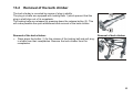
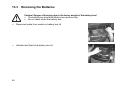
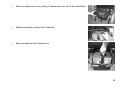
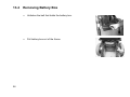
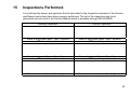
1
Invacare® Mistral
Power Wheelchair
Operating Instructions
How can you get in touch with Invacare®?
If you have any questions or need support, please contact your authorised Invacare® Dealer first. He has the
necessary know-how and equipment plus the special knowledge concerning your Invacare® product which
enables him to offer you all-round satisfactory service. Should you wish to contact us directly, you can reach
us in Europe at the following addresses and phone numbers.
INVACARE® Deutschland GmbH
Dehmer Str. 66
D-32549 Bad Oeynhausen
Deutschland
! (Kundendienst):
+49 - (0) 5731 - 754 580
! (Technische Hotline): +49 - (0) 5731 - 754 570
Fax (Kundendienst):
+49 - (0) 5731 - 754 216
Fax (Technische Hotline):+49 - (0) 5731 - 754 208
Invacare® A/S
Sdr. Ringvej 39
2605 Brøndby
Danmark
! (Kundeservice):
Fax (Kundeservice):
INVACARE®, SA
c/ Areny, s/n
Poligon Industrial de Celrà
17460 Celrà (Girona)
ESPAÑA
!:
+34 - (0) 972 - 49 32 00
Fax:
+34 - (0) 972 - 49 32 20
INVACARE® POIRIER
Les Roches
F-37230 Fondettes
France
! (Service Après-Vente):+33 - (0) 2 47 - 62 64 15
Fax (Service Après-Vente):+33 - (0) 2 47 - 62 64 64
INVACARE® (UK) Ltd
South Road
Bridgend
Mid Glamorgan - CF31-3PY
United Kingdom
! (Customer Service): +44 - (0) 1656 - 647 372
Fax (Customer Service): +44 - (0) 1656 - 649 016
Mecc San S.R.L.
Via Dei Pini, 35
I - 36016 Thiene (VI)
ITALIA
!:
Fax:
2
+45 - (0) 3690 0000
+45 - (0) 3690 0001
+39 - (0) 445-380059
+39 - (0) 445-380034
Invacare® AS
Grensesvingen 9
0603 Oslo
Norge
! (Kundeservice):
Fax (Kundeservice):
+47 - 22 57 95 10
+47 - 22 57 95 01
INVACARE® PORTUGAL Lda
Rua Senhora de Campanhã, 105
4369-001 Porto
PORTUGAL
!:
+352-225105946
Fax:
+352-225105739
INVACARE® NEDERLAND
Celsiusstraat 46
NL-6716 BZ Ede
The Netherlands
!:
+31 - (0) 318 - 69 57 57
Fax:
+31 - (0) 318 - 69 57 58
INVACARE® AB
Fagerstagatan 9
163 91 Spånga
Sverige
! (Kundtjänst):
Fax (Kundtjänst):
[email protected]
+46 - (0) 8 761 70 90
+46 - (0) 8 761 81 08
Service
Invacare
JÄRFÄLLA
!:
+46 - (0) 8 – 621 08 44
Fax:
+46 - (0) 8 – 621 08 45
[email protected]
Invacare® S.A. Belgium
Autobaan 14
8210 Loppem (Brugge)
BELGIUM
! (Kundeservice):
Fax (Kundeservice):
MÖLNDAL
!:
+46 - (0) 31 – 86 36 00
Fax:
+46 - (0) 31 – 86 36 06
[email protected]
+32 (50) 831010
+32 (50) 831011
LANDSKRONA
!:
Fax:
[email protected]
+46 - (0) 418 – 285 40
+46 - (0) 418 – 180 89
OSKARSHAMN
!:
+46 - (0) 491 – 101 40
Fax:
+46 - (0) 491 – 101 80
[email protected]
3
Table of Contents
Chapter
1
Page
Introduction .....................................................................................7
1.1
1.2
2
Safety Notes...................................................................................10
2.1
2.2
2.3
3
4
Before driving for the first time............................................................................................19
Taking Obstacles ................................................................................................................20
Driving up and down gradients ...........................................................................................21
Parking and Standstill .........................................................................................................21
Pushing the wheelchair by hand..................................................22
6.1
7
Removing / inserting armrest..............................................................................................17
Driving ............................................................................................19
5.1
5.2
5.3
5.4
6
General Safety Notes .........................................................................................................10
Safety Information on Electromagnetic Interference ..........................................................13
Safety Information on Driving and Freewheel Mode ..........................................................14
The most important parts .............................................................16
Getting in and out of the wheelchair ...........................................17
4.1
5
Important symbols in this manual .........................................................................................9
Type Classification and Area of Use ....................................................................................9
Disengaging Motors............................................................................................................22
The Joystick Box ...........................................................................23
7.1 Components and controls on the Joystick Box...................................................................23
7.1.1 Status Display..................................................................................................................24
7.1.2 Battery Charge Display....................................................................................................24
7.1.2.1 Deep discharge protection............................................................................................24
4
7.1.3 Activating and deactivating the Interlock .........................................................................25
7.2 Controlling the wheelchair with the Joystick Box................................................................26
7.2.1 How the wheelchair reacts to Joystick movements.........................................................27
7.2.2 Error Codes .....................................................................................................................28
8
Seating systems ............................................................................30
8.1 Standard Seat.....................................................................................................................30
8.1.1 Adjusting Seat Angle .......................................................................................................30
8.1.2 Adjustment of the back inclination by means of a punched plate (optional) ...................31
8.2 Armrests / side parts...........................................................................................................32
8.2.1 Adjusting height of armrest ..............................................................................................32
8.2.2 Adjusting width of side parts ............................................................................................32
8.3 Adjusting Headrest .............................................................................................................33
8.3.1 Adjusting Height of Headrest...........................................................................................33
8.3.2 Adjusting Headrest Angle ................................................................................................33
9
Footrests and Legrests.................................................................34
9.1 "Standard 80" Footrest .......................................................................................................34
9.1.1 General ............................................................................................................................34
9.1.2 Removing Footrest ..........................................................................................................35
9.1.3 Adjusting Length of Footrest............................................................................................36
10
Electrical System...........................................................................37
10.1 Electronics Protection System ..........................................................................................37
10.1.1 The main fuse ................................................................................................................38
10.2 Batteries............................................................................................................................39
10.2.1 What you need to know about batteries ........................................................................39
10.2.2 Charging the batteries ...................................................................................................41
10.2.3 Removing and fitting batteries .......................................................................................43
10.2.3.1 Removing the batteries...............................................................................................44
10.2.3.2 Connecting the New Batteries ....................................................................................45
10.2.3.3 How to handle damaged batteries correctly ...............................................................46
5
11
12
Care and maintenance ..................................................................47
Repair Instructions........................................................................50
12.1
13
Transport........................................................................................52
13.1
13.2
13.3
13.4
13.5
13.6
13.7
13.8
13.9
14
15
6
Repairing a flat tyre...........................................................................................................50
Removing Legrests...........................................................................................................52
Removal of the kerb climber .............................................................................................53
Removing the Batteries ....................................................................................................54
Removing Battery Box ......................................................................................................56
Removing the Headrest ....................................................................................................57
Loosening the backrest cross-bar ....................................................................................58
Folding the Wheelchair .....................................................................................................59
Unfolding the Wheelchair..................................................................................................60
Reassembling the Wheelchair ..........................................................................................61
Technical Specifications...............................................................62
Inspections Performed..................................................................63
1
Introduction
Dear User,
We thank you for the confidence you have placed in our products and are sure that you will enjoy your new
Invacare® Mistral very much.
The advantages at a glance:
• Maximum manoeuvrability in the smallest places.
• Easy transport made possible by easy removal of the batteries and a foldable chassis.
• High-performance motors for an optimum driving behaviour.
• Easy control due to a clearly arranged joystick box.
• Easy maintenance due to a clear construction.
This wheelchair is designed to fit the needs of a wide range of users with different requirements. Whether or
not this model is suitable for a particular user is at the sole discretion of specialised medical personnel, who
have the appropriate qualifications.
Invacare® and its legal representatives assume no liability in cases where a wheelchair is not suitable for a
particular user.
7
These operating instructions contain important information on the following subjects:
• Safety
• Operation
• Care and maintenance.
Please familiarize yourself well with the operating instructions before making your first ride.
Some of the required maintenance jobs or adjustments can be performed by the user or by an
attendant. Certain adjustments, however, require technical training and may only be performed by
your specialised Invacare® dealer. Any damage or errors resulting from not complying with the
operating instructions, or due to incorrect maintenance are excluded from the warranty.
The information provided in these instructions can be changed without advance notice. Errors excepted.
This booklet contains information protected by copyright. It may not be reprinted or reproduced
in whole or in part without the prior written consent of Invacare®.
8
1.1
Important symbols in this manual
WARNING: This symbol warns you of danger!
• Follow the instructions to avoid injury to the user or damage to the product!
NOTE:
This symbol indicates hints and suggestions which should help make operating the product
easier and point out special functions.
REQUIREMENTS:
• This symbol indicates a list of the different tools and other requirements you will need to do
certain maintenance work.
1.2
Type Classification and Area of Use
This wheelchair has been classified as class B (for indoor and outdoor areas). It has been
successfully tested for its safety according to German and international standards. When equipped
with an appropriate lighting system, the wheelchair is suitable to be driven on public roads.
WARNING: Danger of injury to occupant and damage to wheelchair if driver is not
mentally and physically able to keep full control of the vehicle at all times!
• If necessary, operation of the Powerchair must be performed by an attendant!
9
2
Safety Notes
•
2.1
READ WELL BEFORE OPERATION!
General Safety Notes
Danger of injury if wheelchair is used in any other way than the purpose described in this
manual!
• Adhere strictly to the instructions in this User's Manual!
Danger of injury if the wheelchair is driven when ability to operate a vehicle is impaired by
medication or alcohol!
• Never drive the wheelchair under the influence of medication or alcohol!
Danger of damage or injury if wheelchair is accidentally set into motion!
• Switch the wheelchair off before you get in, get out or handle unwieldy objects!
•
10
Be aware that there are only the motor brakes to stop your wheelchair. When the motors are
disengaged, these brakes are automatically deactivated. For this reason, pushing the
wheelchair by an attendant is only recommended on flat surfaces, never on gradients. Never
leave your wheelchair on a gradient with its motors disengaged. Always re-engage the
motors immediately after pushing the wheelchair.
Danger of injury if the On/Off Button is pressed while the wheelchair is in motion, due to it
coming to an abrupt, sharp stop!
• If you have to brake in an emergency, simply release the joystick which will bring you to a
halt!
Danger of injury when transferring wheelchair to another vehicle for transport with the
occupant seated in it!
• It is always better to transfer the wheelchair to another vehicle without the occupant seated in
it!
•
In case the wheelchair does need to be transferred to another vehicle over a ramp with the
occupant seated in it, always have an attendant stand behind the wheelchair during transfer
to ensure it does not tip over backwards!
Danger of injury, if the wheelchair is used as a vehicle seat without a special restraining
system!
• Only ever use the wheelchair as a vehicle seat in connection with a Wheelchair Restraint
System and with the safety belts of the transporting vehicle! Make sure to follow the
instructions and recommendations issued by the Restraint System's manufacturer!
Danger of injury if maximum permissible load is exceeded!
• Do not exceed the maximum permissible load (see technical specifications)!
Danger of injury if legrests break due to use as a stepping board!
• Do not use the legrests as a stepping board when getting in and out of the wheelchair!
11
Danger of injury due to wrong lifting or dropping of heavy components!
• When maintaining, servicing or lifting any part of your wheelchair, take into account the
weight of the individual components especially the batteries! Be sure at all times to adopt the
correct lifting posture and ask for assistance if necessary!
Danger of falling out of the wheelchair.
• Do not slide forward on the seat, do not lean forward between your knees, do not lean
backwards out over the top of the backrest, for example to reach an object.
•
If restraining systems are installed (such as seat belts), use them each time you drive the
wheelchair.
•
When changing over to a new seat, position the wheelchair as close as possible to the new
seat.
Danger of injury by moving parts!
• Make sure that no injury is incurred by moving parts of the wheelchair, like wheels or a Lifter
Module, especially when children are around!
Danger of fire or breaking down due to electric devices being connected!
• Do not connect any electric devices to your wheelchair that are not expressly certified by
INVACARE® for this purpose! Have all electrical installations done by your authorised
INVACARE® Dealer!
12
2.2
Safety Information on Electromagnetic Interference
This electric vehicle was successfully tested in accordance with international standards as to its
compliance with Electromagnetic Interference (EMI) Regulations. However, electromagnetic fields,
such as those generated by radio and television transmitters, and cellular phones, can influence
the functions of electric vehicles. Also, the electronics used in our vehicles can generate a low level
of electromagnetic interference, which however will remain within the tolerance permitted by law.
For these reasons we ask you to please observe the following precautions:
WARNING: Danger of malfunction due to electromagnetic interference!
• Do not switch on or operate portable transceivers or communication devices (such as radio
transceivers or cellular phones) when the vehicle is switched on!
•
Avoid getting near strong radio and television transmitters!
•
In case the vehicle should be set in motion unintentionally or the brakes are released, switch
it off immediately!
•
Adding electrical accessories and other components or modifying the vehicle in any way can
make it susceptible to electromagnetic interference. Keep in mind that there is no sure way to
determine the effect such modifications will have on the overall immunity of the electronic
system!
•
Report all occurrences of unintentional movement of the vehicle, or release of the electric
brakes to the manufacturer!
13
2.3
Safety Information on Driving and Freewheel Mode
Danger of injury if the wheelchair tips over!
• Only ever negotiate gradients of up to the maximum defined in the Technical Specifications
and only with the backrest and seat tilt in an upright position!
14
•
Only ever drive downhill at a maximum of 2/3 of the top speed! Avoid abrupt braking or
accelerating on gradients!
•
If at all possible, avoid driving on slippery surfaces (such as snow, gravel, ice etc.) where
there is a danger of you losing control over the vehicle, especially on a gradient! If driving on
such a surface is inevitable, then always drive slowly and with the utmost caution!
•
Never attempt to overcome an obstacle when on an uphill or downhill gradient!
•
Never attempt to drive up or down a flight of steps with your wheelchair!
•
Always approach obstacles straight on! Ensure that the front wheels and rear wheels move
over the obstacle in one stroke, do not stop halfway! Do not exceed the maximum obstacle
height (see Technical Specifications)!
•
Avoid shifting your centre of gravity as well as abrupt joystick movements and changes of
direction when the wheelchair is in motion!
•
Never use the wheelchair to transport more than one person!
•
Do not exceed the maximum permissible load!
•
Note that the wheelchair will brake or accelerate if you change the Driving Mode whilst the
wheelchair is in motion!
Danger of breaking down in adverse weather conditions, i.e. extreme cold, in an isolated
area!
• If you are a user with severely limited mobility, we advise that in the case of adverse weather
conditions DO NOT attempt a journey without an accompanying attendant!
Danger of injury if your foot slides off the footrest and gets caught underneath the
wheelchair when it is in motion!
• Make sure each time before you drive the wheelchair that your feet are squarely and securely
in place on the footplates, and that both legrests are properly locked into place!
Danger of injury if you collide with an obstacle when driving through narrow passages
such as doorways and entrances!
• Drive through narrow passages in the lowest Driving Mode and with due caution!
15
3
The most important parts
1. Push handle
2. Backrest
3. Armrest
4. Joystick box
5. Footrests
6. Disengagement
lever
7. Drive motor
8. Battery box
9. Crossbar
16
4
Getting in and out of the wheelchair
4.1
Removing / inserting armrest
To get in and out from the side, the armrest must be removed.
To remove:
• Loosen clamping lever (1).
• Pull side part (2) out of its receptacle.
Insert/Remove
Side Part
To insert:
• Push side part (2) into its receptacle.
• Tighten clamping lever (1).
Danger of injury by stay bars that are not duly fixed. The seat angle can become
maladjusted automatically under the effect of jerks caused by abrupt braking or driving
movements!
• When tightening the wing screws, please see to it that these are safely engaged with the
recesses of the stay bars!
17
Getting into the wheelchair:
•
Position your wheelchair as close as possible to your seat. This might
have to be done by an attendant.
•
Switch your wheelchair off.
•
Apply the hand brake of your wheelchair (if existing).
•
Detach the side part of your wheelchair or swivel it up.
•
Now slide into the wheelchair.
Getting out of the wheelchair:
•
Drive your wheelchair as close as possible to your seat.
•
Switch your wheelchair off.
•
Apply the hand brake of your wheelchair (if existing).
•
Detach the side part of your wheelchair or swivel it up.
•
Now slide onto your new seat.
NOTE:
If you not have sufficient muscle strength, you should by all means ask other persons for help.
Use a sliding board, if possible.
18
5
Driving
5.1
Before driving for the first time...
Before you take your first trip, you should familiarise yourself well with the operation of the vehicle
and with all operating elements. Take your time to test all functions and driving modes.
NOTE:
If installed, use the restraining systems (seat belts) each time you use the vehicle.
Sitting Comfortably = Driving Safely
Before each trip, make sure that:
•
You are within easy reach of all operating elements.
•
The battery charge is sufficient for the distance intended to be covered.
•
The seatbelt is in perfect order.
19
5.2
Taking Obstacles
Your Invacare® Mistral can climb kerbs and other obstacles of the following heights.
• Invacare® Mistral without kerb climber ......... 4 cm
• Invacare® Mistral with kerb climber .............. 8 cm
CAUTION: Danger of Tipping Over!
• Never approach obstacles at an angle!
•
Put your backrest into an upright position before climbing an obstacle!
Driving up over an obstacle
•
Correct
Approach the kerb or obstacle slowly head-on. Shortly before the front
wheels or kerb-lifter touch the obstacle, increase the speed and reduce
only after also the rear wheels have climbed the obstacle.
Driving down off of an obstacle
•
20
Approach the kerb or obstacle slowly head-on. Before the front wheels
Incorrect
touch the obstacle, reduce the speed and keep it until also the rear wheels
have climbed the obstacle.
5.3
Driving up and down gradients
The Invacare® Mistral has a safe climbing ability of 17%. When travelling uphill or downhill, you
should by all means observe the following warnings:
WARNING: Danger of tipping over!
• Only ever drive downhill at a maximum of 2/3 of the top speed!
5.4
•
Always return the backrest of your seat or the seat tipper to an upright position before
ascending slopes! We recommend that you lean the seat backrest or the seat tipper slightly
to the rear before descending slopes!
•
Never attempt to ascend or descend a slope on slippery surfaces or where there is a danger
of skidding (such as wet pavement, ice etc)!
•
Avoid trying to get out of the vehicle on an incline or a gradient!
•
Always drive straight in the direction the road or path you are on goes, rather than attempting
to zigzag!
•
Never attempt to turn around on an incline or a slope!
Parking and Standstill
When parking your vehicle or if your vehicle is stationary for a prolonged period:
•
Switch the vehicle's power system off (ON-/OFF key).
•
Activate your anti-theft lock, if existing.
21
6
Pushing the wheelchair by hand
The motors of the wheelchair are equipped with automatic brakes, preventing that the wheelchair
starts rolling out of control when the joystick box is switched off. When pushing the wheelchair, the
magnetic brakes must be disengaged.
6.1
Disengaging Motors
Danger of the vehicle running away!
• When the motors are disengaged (for push operation), the electromagnetic motor brakes are
deactivated! When the vehicle is parked, the levers for engaging and disengaging the motors
must without fail be locked firmly into the "DRIVE" position (electromagnetic motor brakes
activated)!
The disengagement lever is located at the right side of the
wheelchair.
Disengage Motors (1)
•
Switch off joystick box.
•
Pull lever upwards.
Engage Motors (2)
•
22
Press lever downwards.
Lever for engagement
and disengagement of
the motors
7
The Joystick Box
7.1
Components and controls on the Joystick Box
Top
Bottom
1.
2.
3.
4.
5.
6.
7.
8.
9.
10.
11.
Battery charge display
ON/OFF-Button
ON/OFF-LED / Status Display
REDUCE SPEED Button
Joystick
Interlock (key symbol)
INCREASE SPEED Button
Driving Speed Display
Horn
Programming socket
Charging socket
23
7.1.1
Status Display
The ON/OFF LED also serves as an Error Code Display (Status Display). For more information on Error
Codes see chap. "Error Codes" on page 28.
7.1.2
Battery Charge Display
All LED's are lit:
Yellow and red LED's are lit:
Full range
Reduced range:
• Charge batteries after use.
7.1.2.1
Only red LED's are still lit and /
or flashing:
Battery reserve = range very
reduced
• Charge Batteries as soon as
possible!
Deep discharge protection
After driving a certain length of time on battery reserve, the electronic system switches the wheelchair OFF
to protect the batteries from deep discharging.
24
7.1.3
•
Activating and deactivating the Interlock
Touch the Interlock Key Symbol on the Joystick Box with the end of the
magnetic key, which has the Invacare® logo on it.
Interlock
The horn beeps once. The Interlock is activated / deactivated.
Magnetic key
25
7.2
•
Controlling the wheelchair with the Joystick Box
Switch the Joystick ON (ON/OFF Button)
The LED's on the Joystick Box light up. The wheelchair is ready for use.
In case the wheelchair does not react after being switched ON, check the following:
The Interlock (see chapter "Activating and deactivating the Interlock" on page 25).
The Status Display (see chapter "Error Codes" on page 28.)
•
•
Select the desired speed using the REDUCE SPEED / INCREASE SPEED Buttons
The Driving Speed Display shows the selected speed: 1 (slow) to 5 (fast).
Gently move the Joystick in the desired direction (see chapter "How the wheelchair reacts to Joystick" on
page 27).
NOTE:
The electronic system is programmed at the factory with standard values. Your Invacare® Dealer
can individually re-program your wheelchair to better suit your particular needs.
26
7.2.1
How the wheelchair reacts to Joystick movements
Direction of travel for wheelchairs
with rear-wheel drive.
The farther the Joystick is moved in any direction,
the more dynamically the wheelchair reacts.
NOTE:
To brake quickly, just let go of the Joystick. It automatically returns to a neutral position, causing the
wheelchair to brake.
27
7.2.2
Error Codes
The electronic system is able to detect and correct some faults automatically. If successful, the Status
Display will quit flashing. To perform this test, turn the Joystick Box OFF, wait 5 seconds, and then turn it
back ON again. Repeat this procedure a few times, if necessary. If the problem persists, proceed to localise
the source of the problem using the following Error Codes:
Error Codes:
Flash Code:
Meaning:
First Aid:
1 Flash
2 Flashes
3 Flashes
Module defective.
Accessory failure.
Lifter raised.
•
Right motor fault.
Connection is loose or
faulty.
Left motor fault.
Connection is loose or
faulty.
•
Lower Lifter
completely.
Check connectors.
•
Check connectors.
4 Flashes
28
What to do if the
problem persists:
• Contact dealership.
• Contact dealership.
•
Contact dealership
•
Contact dealership
Flash Code:
Meaning:
5 Flashes
General fault / brake fault •
on right motor.
Connection loose or
faulty.
Motors disengaged
•
6 Flashes
7 Flashes
8 Flashes
9 or 10 Flashes
11 Flashes
12 Flashes
First Aid:
Check connectors.
General fault / brake fault
on left motor. Connection
loose or faulty.
Batteries deepdischarged.
Battery voltage too high.
Bad data transfer
between modules.
Motors overloaded.
•
Engage motors.
Switch Joystick OFF
and then back ON
again.
Check connectors.
•
Charge batteries.
Compatibility problems
between the modules.
-
•
Switch Joystick OFF
and then back ON
again.
What to do if the
problem persists:
• Contact dealership
-
•
Contact dealership
•
Contact dealership
•
•
Contact dealership
Contact dealership
•
Contact dealership
29
8
Seating systems
8.1
Standard Seat
8.1.1
Adjusting Seat Angle
•
•
•
Loosen both Allen screws (1) at the stay rods.
Adjust seat angle by lifting and lowering the seat frame.
Tighten again both Allen screws (1).
Adjusting Seat Frame
Danger of injury by stay bars that are not duly fixed. The seat angle can become
maladjusted automatically under the effect of jerks caused by abrupt braking or driving
movements!
• When tightening the wing screws, please see to it that these are safely engaged with the
recesses of the stay bars!
30
8.1.2
Adjustment of the back inclination by means of a punched plate (optional)
The inclination of the backrest is adjusted by means of the borehole plates,
Position of the Borehole
which are attached to the backrest.
Plate
The inclination is adjusted by selecting different pairs of holes, allowing for
adjustment angles between 0° and 36°, in increments of 4.5° (see illustration).
Adjusting the backrest inclination:
• Remove fastening screws on both sides of the backrest frame using an
Allen key.
• Determine the boreholes for the desired inclination by means of the
illustration of the plate.
• Tighten the backrest frame through the appropriate boreholes.
Punched Plate
NOTE:
It will be easier to place the screwing if the backrest is being held by a second person.
31
8.2
Armrests / side parts
8.2.1
Adjusting height of armrest
8.2.2
32
•
Loosen wing screw (1).
•
Push armrest to the desired height.
•
Retighten the wing screw.
Adjusting width of side parts
•
Loosen clamping lever (1).
•
Pull side parts (2) out until the desired width is reached.
•
Retighten the clamping lever.
Adjustment of Armrest
Height
8.3
Adjusting Headrest
8.3.1
Adjusting Height of Headrest
•
•
•
Loosen clamping lever (1).
Push headrest to the desired height.
Tighten clamping lever.
8.3.2
Height Adjustment
Adjusting Headrest Angle
• Loosen clamping lever (2).
• Swivel headrest into the desired position.
• Tighten clamping lever.
Adjustment of Position
33
9
Footrests and Legrests
9.1
"Standard 80" Footrest
9.1.1
General
The angle (80°) of the footrest in relation to the seating surface is fixed. The
length of the footrest is adjustable.
The adjustment of the footrest is performed with the corresponding tools.
34
"Standard 80" Footrest
9.1.2
Removing Footrest
• Unlock footrest by pressing or pulling the catch lever (1).
• Swivel footrest outward by approx. 90° (2).
Unlocking Footrest
• Pull footrest upward from its receptacle.
Removing Footrest
35
9.1.3
Adjusting Length of Footrest
Tools:
1x Wrench; 10 mm
1x Allen key; 5 mm
• Loosen fastening screw using the 4 mm Allen key and 10 mm wrench, and
remove.
• Adjust footrest to the desired height and align holes.
• Insert fastening screws into the holes.
• Screw off self-locking nut.
• Tighten fastening screw using the Allen key and the spanner.
36
Adjust length
10
Electrical System
10.1
Electronics Protection System
The vehicle's electronics are equipped with an overload-protection system.
If the motors are put under considerable strain for a longer period of time (for example, when
driving up a steep hill) and especially when the ambient temperature is high, then the electronic
system could overheat. In this case the vehicle's power is reduced gradually until it finally comes to
a halt. The Status Display shows a corresponding error code. By switching the power supply off
and back on again, the error code is cancelled and the electronics are switched back on. It will take
approximately five minutes until the electronics have cooled down enough that the motors deliver
their full power again.
When the motors are stalled by an insurmountable obstacle, such as a high kerb, and the vehicle
driver allows the motors to strain against this hindrance for more than 20 seconds without moving,
then the electronics will automatically switch off to prevent the motors from being damaged. The
Status Display shows a corresponding error code. By switching the Joystick Box off and back on
again, the error code is cancelled and the electronics are switched back on.
37
10.1.1 The main fuse
The entire electric system of the wheelchair is protected against overload by two master fuses.
The master fuses are either directly mounted to the positive poles of the batteries or to the lower
side of the battery lid. They can be replaced only after dismounting the battery lid.
NOTE
A defective main fuse may be replaced only after checking the entire electric system. An
Invacare® specialised dealer must perform the replacement.
38
10.2
Batteries
10.2.1 What you need to know about batteries
Power is supplied to the vehicle by two 12V gel batteries. The batteries are maintenance-free and
only need regular charging.
New batteries should always be once fully charged before their first use. New batteries will be at
their full capacity after having run through approx. 10 - 20 charging cycles. How fast the batteries
will be discharged will depend on many circumstances, such as ambient temperature, condition of
the surface of the road, tyre pressure, weight of the driver, way of driving and utilisation of lighting,
etc.
39
NOTE:
Pay attention to the Battery Charge Indicator! Make sure to charge the batteries when the
Battery Charge Indicator shows that battery charge is low. We recommend charging the batteries
after each trip, as well as each night over night. Depending on the level of discharge, it can take
up to 12 hours until the batteries are fully charged again.
Protect your charger for sources of heat such as heaters and direct sunlight. If the battery
charger overheats, charging current will be reduced and the charging process delayed.
To avoid damaging the batteries, never allow them to be fully discharged. Do not drive on heavily
discharged batteries if it is not absolutely necessary, as this will strain the batteries unduly and
greatly shorten their life expectancy.
In case your vehicle is not used for a longer period of time, then the batteries must be charged at
least once a month to maintain a full charge. Alternatively, the vehicle can stay connected to the
charger. The batteries cannot be overcharged with the specified charger.
40
10.2.2 Charging the batteries
•
Make sure you read and understand the battery charger's User's Manual, as well as the safety
notes on its front and rear panels!
WARNING:
Danger of explosion and destruction of batteries if the wrong battery charger is used!
• Only ever use the battery charger supplied with your vehicle!
Danger of electric shock and damage to the battery charger if it is allowed to get wet!
• Protect the battery charger from water!
Danger of short circuit and electric shock if the battery charger has been damaged!
• Do not use the battery charger it has fallen on the ground or been damaged!
Danger of fire and electric shock if a damaged extension cable is used!
• Only ever use an extension cable if it is absolutely necessary! In case you must use one,
make sure it is in good condition!
41
The charging socket is on the bottom of the Joystick Box.
Connecting the charger
Proceed in the following order:
• Connect the battery charger to the Joystick Box.
•
Connect the battery charger to the mains power supply and
switch on.
Disconnecting the charger
Proceed in the following order:
• Disconnect the battery charger from the mains power supply.
•
42
Disconnect the battery charger from the Joystick Box.
10.2.3 Removing and fitting batteries
WARNING:
Danger of injury if the batteries are not handled correctly during assembly and
maintenance work!
• Batteries may only be removed and installed by authorised technicians!
•
Observe the warnings on the batteries!
•
Take into account the heavy weight of the batteries!
•
Only ever use the battery type defined in the technical specifications!
Danger of fire and burns if battery terminals are short-circuited!
• DO NOT short-circuit battery terminals with a tool!
WARNING:
Corrosion and burns from acid leakage if batteries are damaged!
• Remove clothes that have been soiled by acid immediately!
After contact with skin:
• Immediately wash affected area with lots of water!
After contact with eyes:
• Immediately rinse eyes under running water for several minutes; consult a physician!
43
10.2.3.1 Removing the batteries
Requirements:
• Wrench 10 mm
•
Wrench 13 mm
•
Wrench 19 mm
NOTE
The removal of the batteries from the battery box is described in detail in chapter "Removing the
Batteries" on page 54.
44
•
Open battery carrying strap (1).
•
Detach the cover of the battery.
•
Loosen battery clamp (1) of the blue cable at the negative pole
of the battery by means of a wrench and remove cable.
•
Loosen the battery clamp (1) of the red cable at the positive pole
of the battery by means of a wrench and remove cable.
10.2.3.2 Connecting the New Batteries
•
Fasten battery clamp (2) of the red cable to the positive pole of
the battery and tighten by means of a wrench.
•
Fasten battery clamp (2) of the blue cable to the negative pole of
the battery and fasten by means of a wrench.
•
Lash down carrying strap as shown in the photo.
•
Secure the cover by tightening the tensioning strap.
45
10.2.3.3 How to handle damaged batteries correctly
WARNING:
Corrosion and burns from acid leakage if batteries are damaged!
• Remove clothes that have been soiled by acid immediately!
After contact with skin:
• Immediately wash affected area with lots of water!
After contact with eyes:
• Immediately rinse eyes under running water for several minutes; consult a physician!
Requirements:
• Safety goggles
•
Acid-resistant gloves
•
Acid-resistant receptacle for transportation
•
Always wear appropriate safety clothing when handling damaged batteries.
•
Place damaged batteries in an acid-resistant receptacle immediately after removing them.
•
Only ever transport damaged batteries in an appropriate acid-resistant receptacle.
•
Wash all objects that have come into contact with acid with lots of water.
Disposing of dead or damaged batteries correctly
Dead or damaged batteries can be given back to your dealer or directly to Invacare®.
46
11
Care and maintenance
NOTE:
Have your vehicle checked once a year by an authorised Invacare® dealer in order to maintain
it's driving safety and roadworthiness.
Cleaning the vehicle
When cleaning the vehicle, pay attention to the following points:
•
Only use a damp cloth and gentle detergent.
•
Do not use any scrubbing agents.
•
Do not subject the electronic components to any direct contact with water.
•
Do not use high-pressure cleaning devices.
47
Seat and backrest padding:
- Check for perfect condition.
Side part and armrest:
- Are all fastening elements installed?
- Can armrests / side parts be removed and installed without too much
physical effort?
- Are armrests secured in their positions?
Legrests:
- Do legrests lock into place without any problem?
- Do the different adjustment functions work without any problem?
Tyres:
- Have tyres checked for specified air pressure (2,5 bar).
Front wheel forks / Front wheels
- Front wheels must be running smoothly.
- If wheels are wobbling or turn heavily, adjust steering pivot pin or front
wheel bearing
- Check fork bearing for firm seat.
Rear wheels:
- Test wheel for firm seat on the axle drive shaft.
- Rear wheels must turn without wobbling
48
Monthly
Weekly
When
Delivered
Maintenance Jobs
Electronics / Electrical System:
- Check all plug connections for condition and firm seat.
- Have all batteries been fully charged before the daily operation?
- Are all holders, screws firmly fixed, tight and safe?
- Are all electric bulbs of the lighting system (if applicable) in working
order?
Cleaning:
- Clean all parts carefully.
Monthly
Weekly
When
Delivered
Maintenance Jobs
Before every trip
Before each trip
When necessary
Once a year you should have your wheelchair inspected and serviced by your authorised
dealer. If the wheelchair is serviced at regular intervals, damaged or worn parts can be
located and replaced in time, thus preserving it in good working order. A complete checklist
of necessary maintenance work can be found in the Service Manual, which can be obtained
from Invacare®.
49
12
Repair Instructions
12.1
Repairing a flat tyre
WARNING: Danger of the wheelchair running away!
• Engage the motors!
• Prevent the wheelchair from rolling away when jacking it up by placing wedges under the
wheels!
Tools:
• Allen key, 5 mm
Removing the rear wheel
• Loosen the screws that hold the wheel (1).
• Jack up the wheelchair.
• Remove the screws (1).
• Remove wheel from hub.
• Repair flat tyre.
• Replace wheel on hub.
• Replace screws and tighten.
• Make sure the wheel is mounted on the same side and turning in the
same direction as was before disassembly.
50
Remove wheel
Repairing a flat
• Remove valve cap.
• Let the air out of the tyre by pressing the pin in the centre of the valve.
• Remove screws that hold the rim together.
• Remove the tyre and the inner tube from the wheel.
• Repair the inner tube, or replace with a new one.
• Place the inner tube in the tyre.
• Fill the inner tube with a little bit of air.
• Position the rim-halves from both sides of the tyre.
• Replace the screws and tighten.
• Pump up the tyre to the pressure specified in the technical data.
51
13
Transport
The preparations for transport are to be performed in the following order:
• Remove legrests.
• Remove kerb climber (available as an option and not always mounted).
• Remove the backrest crossbar
• Detach all connection cables.
• Remove batteries.
• Remove battery box.
• The battery box can also be removed without taking out the batteries. However, due to the heavy weight
of the component, this should be done by two persons only.
• Remove cushion of the seat.
• Fold wheelchair and ship.
The assembly of the wheelchair is to be done analogously in reverse order.
13.1
Removing Legrests
NOTE:
The disassembly of the legrests depends on their design. For further information see chap.
"Removing Footrest" on page 35.
52
13.2
Removal of the kerb climber
The kerb climber is mounted by means of plug-in shafts.
The plug-in shafts are equipped with locking balls 1) which prevent that the
plug-in shaft slips out of its receptacle.
The locking balls are released by pressing down the release button (2). This
will make possible the quick attachment and removal of the kerb climber.
Removal of the kerb climber:
• Press down the button (1) for the release of the locking ball and pull plugin shafts from their receptacles. Remove the kerb climber from the
receptacles.
Removal of kerb climber
53
13.3
Removing the Batteries
Caution! Danger of bruising due to the heavy weight of the battery box!
• The battery box should be lifted by two persons only.
• Do not reach under the battery box.
•
Disconnect cable from socket on battery box lid.
•
Unfasten belt that holds battery box lid.
54
•
Remove battery box lid by pulling it towards the rear out of the wheelchair.
•
Disconnect battery cables from batteries.
•
Remove batteries from battery box.
55
13.4
56
Removing Battery Box
•
Unfasten the belt that holds the battery box.
•
Pull battery box out of the frame.
13.5
Removing the Headrest
To remove the headrest:
• Loosen the clamping lever (1).
• Pull the headrest from its support (2).
Removing Headrest
57
13.6
Loosening the backrest cross-bar
Loosen the crossbar
58
•
Loosen the thumbscrews at both ends of the
crossbar (1).
•
Unhook the crossbar on the right side and swing
away.
13.7
Folding the Wheelchair
Step 1
Step 2
Step 3
•
•
•
•
Remove seat cushion.
Lean wheelchair to one side.
Pull seat plate up by its front
and rear edges.
Push together.
59
13.8
Unfolding the Wheelchair
WARNING: Danger of injury!
• When pushing the seat down, make sure not to get your fingers caught between the two
seat panels!
•
•
•
60
To unfold, lift the wheelchair slightly from one side and open by pressing
apart the backrest handles and the armrests.
Hold the seat plate downward by its front and back edges until it has
completely reached its lower position.
Place seat cushion on top of the seat.
Pressing Down
Seat Plate
13.9
Reassembling the Wheelchair
NOTE:
The assembly of the wheelchair is performed in reverse order in relation to the disassembly.
CAUTION: Danger of injury if the battery box is not safely locked into place!
• After the assembly of the wheelchair, it must be ensured that the retaining bolts that keep
the battery case in place, are safely locked! To make sure, shake and pull at the battery
box!
61
14
Technical Specifications
Electric System
Batteries
Battery master fuse
Weight
Empty weight
Max. additional weight (Payload)
Driving properties
Travelling range
as per ISO 7176
• 31 AH, MU-1SLD G
• 50 AH, M22NF SLD G
• 2x 50 A (1x per Battery)
• approx. 64 kg (with 31 Ah batteries)
• approx. 80 kg (with 50 Ah batteries)
• 120 kg
• 31 Ah = approx. 20 km
• 50 Ah = approx. 30 km
Note: The travelling range of a wheelchair depends largely on external conditions, such as charging status of the batteries, ambient temperature, local
topography, condition of the surface of the road, tyre pressure, driver's weight, way of driving and utilization of the battery for lighting, servos etc.
Travelling speed
Climbing ability
Maximum obstacle height
Dimensions
Height
Width
Length
Tyres
Tyre pressure (rear)
62
•
•
•
•
6 km/h
max. 17%
with kerb climber = max. 8 cm
without kerb climber = max. 4 cm
•
•
•
approx. 92 cm
approx. 62 cm
approx. 108 cm
•
2,5 bar (40 psi)
15
Inspections Performed
It is confirmed by stamp and signature that all jobs listed in the inspection schedule of the Service
and Repair Instructions have been properly performed. The list of the inspection jobs to be
performed can be found in the Service Manual which is available through INVACARE®.
Delivery Inspection
1st Annual Inspection
Stamp of authorised Dealer / Date / Signature
Stamp of authorised Dealer / Date / Signature
2nd Annual Inspection
3rd Annual Inspection
Stamp of authorised Dealer / Date / Signature
Stamp of authorised Dealer / Date / Signature
4th Annual Inspection
5th Annual Inspection
Stamp of authorised Dealer / Date / Signature
Stamp of authorised Dealer / Date / Signature
63
64
Order No. of this Manual: B292003.DOC
Release Date: 21.05.01
English