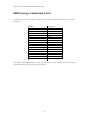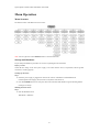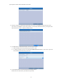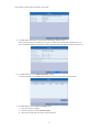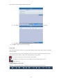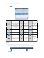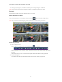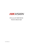
1
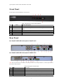
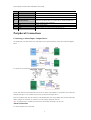
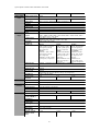
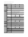
Quick Operation Guide
Ultimax 1200
Ultimax 1300
Ultimax 1400
Quick Operation Guide of DS-7200-SH/SV Series DVR
Thank you for purchasing our product. If there is any question or request, please do not hesitate to contact dealer.
This manual is applicable to DS-7204HVI-SH, DS-7208HVI-SH, DS-7216HVI-SH; DS-7204HFI-SH, DS7208HFI-SH, DS-7216HFI-SH; DS-7204HWI-SH, DS-7208HWI-SH, DS-7216HWI-SH; DS-7204HVI-SV, DS7208HVI-SV and DS-7216HVI-SV series DVR.
DVR Pre-Installation
The DS-7200-SH/SV Series DVR is highly advanced surveillance equipment that should be installed with care.
Please take into consideration the following precautionary steps before installation of the DVR.
1. Keep all liquids away from the DVR.
2. Install the DVR in a well-ventilated and dust-free area.
3. Ensure environmental conditions meet factory specifications.
4. Install a manufacturer recommended HDD.
DVR Installation
During the installation of the DVR:
1. Use brackets for rack mounting.
2. Ensure there is ample room for audio and video cables.
3. When installing cables, ensure that the bend radius of the cables are no less than five times than its diameter.
4. Connect both the alarm and RS-485 cable.
5. Allow at least 2cm (~0.75-inch) of space between racks mounted devices.
6. Ensure the DVR is grounded.
7. Environmental temperature should be within the range of -10 ºC ~ 55 ºC, 14ºF ~ 131ºF.
8. Environmental humidity should be within the range of 10% ~ 90%.
Hard Disk Installation
Before you start:
Before installing a hard disk drive (HDD), please make sure the power is disconnected from the DVR. A factory
recommended HDD should be used for this installation.
Tools Required: Screwdriver.
To install a HDD on your DVR:
1. Remove the cover from the DVR by unfastening the screws on the back and side.
2. Install the HDD in the HDD rack using the provided screws. Fasten the screws on the
bottom to fix the HDD.
2
Quick Operation Guide of DS-7200-SH/SV Series DVR
3. Connect the HDD to the motherboard of the DVR with the included data cable.
4. Connect the power cable to the HDD.
5. Re-install the cover of the DVR and fasten screws.
3
Quick Operation Guide of DS-7200-SH/SV Series DVR
Front Panel
The front panel of DS-7200-SH/SV is shown below:
Table 1 Description of Control Panel Buttons
No.
Name
Function Description
1
POWER
POWER indicator turns green when DVR is powered up.
2
STATUS
STATUS indicator lights in red when data is being read from or written to
3
Tx/Rx
4
USB Interface
5
IR Receiver
HDD.
Tx/Rx indictor blinks green when network connection is functioning properly.
Connects USB mouse or USB flash memory devices.
Receiver for IR remote.
Rear Panel
DS-7204HVI/HFI/HWI-SH and DS-7204HVI-SV:
DS-7208HVI/HFI/HWI-SH and DS-7208HVI-SV:
Note: The rear panel of DS-7216-SH/SV series DVR provides 16 video input interfaces, 16 alarm input interfaces
and 4 alarm output interfaces.
Table 2 Description of Rear Panel
No.
Item
Description
1
VIDEO IN
BNC connector for analog video input.
2
VIDEO OUT
BNC connector for video output.
3
USB Interface
Connects USB mouse or USB flash memory devices.
4
HDMI
HDMI video output.
5
VGA
DB15 connector for VGA output. Display local video output and menu.
4
Quick Operation Guide of DS-7200-SH/SV Series DVR
6
Alarm In/Out
Connector for alarm input/output.
7
AUDIO IN
RCA connector for audio input.
8
AUDIO OUT
RCA connector for audio output.
9
LAN Interface
Connector for LAN (Local Area Network).
10
RS-485 Interface
Connector for RS-485 devices. Connect the D+ and D- terminals to T+
11
12V
12VDC power supply.
12
POWER
GND
Switch for turning on/off the device.
Ground (needs to be connected when DVR starts up).
and T- of PTZ receiver respectively.
13
Peripheral Connections
Connecting to Alarm Input / Output Device
The alarm input is an open/closed relay. If the input is not an open/closed relay, follow the connection diagram
below:
To connect to an AC/DC load, use the following diagram:
For DC load, JP4 can be used within the limit of 12V/1A safely. If the interface is connected to an AC load, JP4
should be left open. Use an external relay for safety (as shown in the figure above).
There are 4 jumpers (JP4, JP5, JP6, and JP7) on the motherboard, each corresponding with one alarm output. By
default, jumpers are connected. To connect an AC load, jumpers should be removed.
Note: An external relay is needed to prevent electric shock when connecting to an AC load.
Alarm Connection
To connect alarm devices to the DVR:
5
Quick Operation Guide of DS-7200-SH/SV Series DVR
1. Disconnect pluggable block from the ALARM IN /ALARM OUT terminal block.
2. Press and hold the orange part of the pluggable block; insert signal cables into slots and release the orange part.
Ensure signal cables are in tight.
3. Connect pluggable block back into terminal block.
RS-485 Connections
To connect RS-485 devices (e.g., pan/tilt unit) to the DVR:
Press and hold the orange part of the pluggable block; insert signal cables into slots and release the orange part.
Ensure signal cables are in tight.
Note: Make sure the pan/tilt receiver unit is connected to the D+ and D- of the RS-485 terminal of DVR.
6
Quick Operation Guide of DS-7200-SH/SV Series DVR
Specifications
Table 3 Specifications for DS-7200HFI-SH
7
Quick Operation Guide of DS-7200-SH/SV Series DVR
Model
Video/Audio
input
Video/Audio
output
DS-7204HFI-SH
External
interface
General
DS-7216HFI-SH
8-ch
16-ch
Video compression
H.264
Video input
4-ch
Video input interface
BNC (1.0 Vp-p, 75 Ω), PAL /NTSC self-adaptive
Audio compression
G.711
Audio input
1-ch / 4-ch, RCA (2.0 Vp-p, 1 kΩ)
Two-way audio input
1-ch, RCA (2.0 Vp-p, 1 kΩ) (using the audio input)
HDMI/VGA output
Encoding resolution
1-ch, resolution:
1-ch, resolution:
1080P:
1080P: 1920×1080/60Hz,
1920×1080/60Hz
SXGA: 1280×1024/60Hz,
UXGA:
720P: 1280×720/60Hz,
1600×1200/60Hz
XGA: 1024×768/60Hz
SXGA:
1280×1024/60Hz
720P: 1280×720/60Hz
XGA: 1024×768/60Hz
1-ch, BNC (1.0 Vp-p, 75 Ω),
resolution: PAL: 704 × 576, NTSC: 704 × 480
4CIF / 2CIF / CIF / QCIF
Frame rate
25 fps (P) / 30 fps (N)
Video bit rate
32 Kbps ~ 3072 Kbps, or user defined (Max. 3072 Kbps)
CVBS output
Hard disk
DS-7208HFI-SH
Audio output
1-ch, RCA (Linear, 1 kΩ)
Audio bit rate
64 Kbps
Dual-stream
Support; Sub-stream: CIF / QCIF @ 25 fps (P) / 30 fps (N))
Stream type
Video, Video & Audio
Synchronous playback
4-ch
8-ch
16-ch
2 SATA interfaces
2 SATA interfaces
SATA
1 SATA interface
Capacity
Up to 4TB capacity
Network interface
1, RJ45 10M / 100M Ethernet interface
Serial interface
1 RS-485 interface, half-duplex
USB interface
2, USB 2.0
Alarm in / out
4/1
Power supply
12 VDC
Consumption
(without HDD or
DVD-R/W)
Working temperature
≤ 10 W
-10 ºC ~+55 ºC
Working humidity
10% ~ 90%
Chassis
Standalone 1U chassis
Dimensions
(W × D × H)
Weight
(without HDD or
DVD-R/W)
8/4
16 / 4
≤ 15 W
≤ 20 W
315 × 230 × 45 mm
19-inch rackmounted 1U chassis
445 × 290 × 45 mm
19-inch rackmounted 1U chassis
445 × 290 × 45 mm
≤ 2 kg
≤ 4 kg
≤ 4 kg
8
Quick Operation Guide of DS-7200-SH/SV Series DVR
Table 4 Specifications for DS-7200HVI-SH
9
Quick Operation Guide of DS-7200-SH/SV Series DVR
Model
Video/Audio
input
Video/Audio
output
DS-7204HVI-SH
DS-7208HVI-SH
DS-7216HVI-SH
8-ch
16-ch
Video compression
H.264
Video input
4-ch
Video input
interface
Audio
compression
Audio input
BNC (1.0 Vp-p, 75 Ω), PAL /NTSC self-adaptive
Two-way audio
input
HDMI/VGA
output
1-ch, RCA (2.0 Vp-p, 1 kΩ) (using the audio input)
CVBS output
Encoding
resolution
Frame rate
G.711
1-ch / 4-ch, RCA (2.0 Vp-p, 1 kΩ)
1-ch, resolution:
1920 × 1080P / 60 Hz ,1600 × 1200 / 60 Hz,1280 × 1024 / 60 Hz, 1280 ×
720 / 60 Hz, 1024 × 768 / 60 Hz
1-ch, BNC (1.0 Vp-p, 75 Ω),
resolution: PAL: 704 × 576, NTSC: 704 × 480
4CIF / 2CIF / CIF / QCIF
Video bit rate
Mode1:
Mode1:
4CIF / 2CIF @ 8 fps
4CIF / 2CIF @6fps
or CIF / QCIF @ 25
or CIF / QCIF @
25 fps (P) / 30 fps
fps (P) / 30 fps (N)
(N) Mode2:
Mode2:
Channel 1& Channel
Channel 1: 4CIF /
5: 4CIF / 2CIF / CIF / 2CIF / CIF / QCIF
@ 25 fps (P) / 30
QCIF @ 25 fps (P) /
fps (N),
30 fps (N),
Other Channels: CIF / Channel 2~16:
CIF / QCIF @ 25
QCIF @ 25 fps (P) /
fps (P) / 30 fps (N)
30 fps (N)
32 Kbps ~ 3072 Kbps, or user defined (Max. 3072 Kbps)
Audio output
1-ch, RCA (Linear, 1 kΩ)
Audio bit rate
64 Kbps
Dual-stream
Support;
Sub-stream: CIF @ 6 fps, QCIF @ 25 fps (P) /30 fps (N))
Video, Video & Audio
Stream type
Mode1:
4CIF / 2CIF @ 12 fps or
CIF / QCIF @ 25 fps
(P) / 30 fps (N)
Mode2:
Channel 1: 4CIF / 2CIF /
CIF / QCIF @ 25 fps
(P) / 30 fps (N),
Channel 2~4: CIF / QCIF
@ 25 fps (P) / 30 fps (N)
Synchronous
playback
4-ch
8-ch
Hard disk
SATA
1 SATA interface
Capacity
Up to 4TB capacity
External
interface
Network interface
1, RJ45 10M / 100M Ethernet interface
Serial interface
USB interface
1 RS-485 interface, half-duplex
2, USB 2.0
Alarm in / out
4/1
General
Power supply
12 VDC
Consumption
(without HDD or
DVD-R/W)
Working
temperature
Working humidity
≤ 10 W
Chassis
Dimensions
(W × D × H)
Weight (without
HDD or DVDR/W)
Standalone 1U chassis
315 × 230 × 45 mm
16-ch
8/4
16 / 4
≤ 10 W
≤ 15 W
≤ 4 kg
≤ 4 kg
-10 ºC ~+55 ºC
10% ~ 90%
≤ 2 kg
10
Quick Operation Guide of DS-7200-SH/SV Series DVR
Table 5 Specifications for DS-7200HVI-SV
Model
Video/Audio
input
Video/Audio
output
DS-7204HVI-SV
16-ch
Video input
4-ch
Video input
interface
Audio compression
BNC (1.0 Vp-p, 75 Ω), PAL /NTSC self-adaptive
G.711
Audio input
1-ch / 4-ch, RCA (2.0 Vp-p, 1 kΩ)
Two-way audio
input
HDMI/VGA output
1-ch, RCA (2.0 Vp-p, 1 kΩ) (using the audio input)
Frame rate
General
8-ch
H.264
Encoding resolution
External
interface
DS-7216HVI-SV
Video compression
CVBS output
Hard disk
DS-7208HVI-SV
1-ch, resolution:
1080P: 1920×1080/60Hz; SXGA: 1280×1024/60Hz;
720P: 1280×720/60Hz; XGA: 1024×768/60Hz
1-ch, BNC (1.0 Vp-p, 75 Ω),
resolution: PAL: 704 × 576, NTSC: 704 × 480
WD1 / 4CIF / 2CIF / CIF / QCIF
WD1 / 4CIF / 2CIF /
CIF / QCIF @ 25 fps
(P) / 30 fps (N)
Video bit rate
WD1 / 4CIF / 2CIF
WD1 @ 8 fps; 4CIF /
@ 15 fps; CIF / QCIF 2CIF @ 10 fps; CIF /
QCIF @ 25 fps (P) /
@ 25 fps (P) / 30 fps
(N)
30 fps (N)
32 Kbps ~ 3072 Kbps, or user defined (Max. 3072 Kbps)
Audio output
1-ch, RCA (Linear, 1 kΩ)
Audio bit rate
64 Kbps
Dual-stream
Support; sub-stream @ CIF / QCIF
Stream type
Video, Video & Audio
Synchronous
playback
4-ch
SATA
1 SATA interface
Capacity
Up to 4TB capacity
Network interface
1, RJ45 10M / 100M Ethernet interface
Serial interface
1 RS-485 interface, half-duplex
USB interface
2, USB 2.0
Alarm in / out
4/1
Power supply
12 VDC
Consumption
(without HDD or
DVD-R/W)
Working
temperature
Working humidity
≤ 10 W
Chassis
Standalone 1U chassis
Dimensions
(W × D × H)
Weight (without
HDD or DVD-R/W)
315 × 230 × 45 mm
8-ch
-10 ºC ~+55 ºC
10% ~ 90%
≤ 2 kg
11
16-ch
8/4
16 / 4
≤ 10 W
≤ 15 W
Quick Operation Guide of DS-7200-SH/SV Series DVR
Table 6 Specifications for DS-7200HWI-SH
12
Quick Operation Guide of DS-7200-SH/SV Series DVR
Model
Video/Audio
input
Video/Audio
output
DS-7204HWI-SH
Video compression
H.264
Video input
4-ch
Video input
interface
Audio compression
BNC (1.0 Vp-p, 75 Ω), PAL /NTSC self-adaptive
G.711
Audio input
1-ch / 4-ch, RCA (2.0 Vp-p, 1 kΩ)
Two-way audio
input
HDMI/VGA
output
1-ch, RCA (2.0 Vp-p, 1 kΩ) (using the audio input)
CVBS output
Encoding
resolution
Hard disk
External
interface
General
DS-7208HWI-SH
8-ch
DS-7216HWI-SH
16-ch
1-ch, resolution:
1080P: 1920×1080/60Hz; SXGA: 1280×1024/60Hz;
720P: 1280×720/60Hz; XGA: 1024×768/60Hz
1-ch, BNC (1.0 Vp-p, 75 Ω),
resolution: PAL: 704 × 576, NTSC: 704 × 480
WD1 / 4CIF / 2CIF / CIF / QCIF
Frame rate
25 fps (P) / 30 fps (N)
Video bit rate
32 Kbps ~ 3072 Kbps, or user defined (Max. 3072 Kbps)
Audio output
1-ch, RCA (Linear, 1 kΩ)
Audio bit rate
64 Kbps
Dual-stream
Support; sub-stream @ CIF/ QCIF
Stream type
Video, Video & Audio
Synchronous
playback
4-ch
8-ch
SATA
1 SATA interface
2 SATA interfaces
Capacity
Up to 4TB capacity for each disk
Network interface
1, RJ45 10M / 100M Ethernet interface
Serial interface
1 RS-485 interface, half-duplex
USB interface
2, USB 2.0
Alarm in / out
4/1
Power supply
12 VDC
Consumption
(without hard disk
or DVD-R/W)
Working
temperature
Working humidity
≤ 10 W
16-ch
8/4
16 / 4
≤ 15 W
≤ 20 W
-10 ºC ~+55 ºC
10% ~ 90%
Chassis
Standalone 1U chassis
19-inch rack-mounted 1U chassis
Dimensions
(W × D × H)
Weight (without
hard disk or DVDR/W)
315 × 230 × 45 mm
445 × 290 × 45mm
≤ 2 kg
≤ 4 kg
13
≤ 4 kg
Quick Operation Guide of DS-7200-SH/SV Series DVR
14
Quick Operation Guide of DS-7200-SH/SV Series DVR
HDD Storage Calculation Chart
The following chart shows an estimation of storage space used based on recording at one channel for an hour at a
fixed bit rate.
Bit Rate
96K
128K
160K
192K
224K
256K
320K
384K
448K
512K
640K
768K
896K
1024K
1280K
1536K
1792K
2048K
Storage Used
42M
56M
70M
84M
98M
112M
140M
168M
196M
225M
281M
337M
393M
450M
562M
675M
787M
900M
Note: Please note that supplied values for storage space used is just for reference. Storage space used is estimated
by formulas and may have some deviation from actual value.
15
Quick Operation Guide of DS-7200-SH/SV Series DVR
Menu Operation
Menu Structure
The menu structure of the DVR is shown as below:
Note: You can right click on the Shutdown button to exit the main menu.
Startup and Shutdown
Proper startup and shutdown procedures are crucial to expanding the life of the DVR.
Before you start:
Check that the voltage of the extra power supply is the same with the device’s requirement, and the ground
connection is working properly.
Starting up the device:
Steps:
1. Check the power supply is plugged into an electrical outlet. It is HIGHLY recommended that an
Uninterruptible Power Supply (UPS) be used in conjunction with the device.
2. Press the POWER button on the rear panel. The Power indicator LED should turn green indicating that the
unit begins to start up.
Shutting down the device:
Steps:
1. Enter the Shutdown menu.
Main Menu > Shutdown
16
Quick Operation Guide of DS-7200-SH/SV Series DVR
2. Click the Shutdown button to enter the following dialog box:
3. Click the Yes button. The following message box pops up:
4. Turn off the power switch on the rear panel of DVR.
Using the Setup Wizard
The Setup Wizard can walk you through some important settings of the device. By default, the Setup Wizard starts
once the device has loaded.
Operating the Setup Wizard:
1. Select the system language from the drop-down menu. The default language is English.
Click Apply to save the resolution settings.
17
Quick Operation Guide of DS-7200-SH/SV Series DVR
2. Check the checkbox to enable Setup Wizard when device starts. Click Next to continue the setup wizard.
You can also click Cancel to exit the Setup Wizard, or use the Setup Wizard next time by leaving the “Start
wizard when device starts?” checkbox checked and exit.
3. Click Next button on the Wizard window to enter the Login window.
1)
Enter the admin password. By default, the password is 12345.
2)
To change the admin password, check the New Admin Password checkbox. Enter the new password
and confirm the password in the given fields.
4. Click the Next button to enter the Date and Time settings window.
Set the time zone, date format, system date and system time.
18
Quick Operation Guide of DS-7200-SH/SV Series DVR
5. Click Next button which takes you back to the Network Setup Wizard window.
Set the network parameters, including the NIC type, IPv4 address, IPv4 subnet mask, default gateway, etc.
You can enable the DHCP to automatically obtain an IP address and other network settings from that server.
6. Click Next button to enter the HDD Management window.
To initialize the HDD, click the Init button. Initialization removes all the data saved in the HDD.
7. Click Next button to enter the Record Settings window.
1)
Select the camera to configure.
2)
Check the checkbox to enable Start Recording.
3)
Select the recording mode to Normal or Motion Detection.
19
Quick Operation Guide of DS-7200-SH/SV Series DVR
4)
Click Copy to copy the record settings of the current camera to other camera (s) if needed.
5)
Click OK to return to the Record Settings window.
8. Click OK to complete the startup Setup Wizard.
Live View
Some icons are provided on screen in Live View mode to indicate different camera status. These icons include:
Live View Icons
In the live view mode, there are icons at the right top of the screen for each channel, showing the status of the
record and alarm in the channel, so that you can find problems as soon as possible.
Alarm (video loss, tampering or motion detection or sensor alarm).
Record (manual record, schedule record, motion detection record or alarm triggered record)
Alarm & Record
Using the Mouse in Live View
In the live view mode, use the mouse to right-click on the window to access the following menu:
20
Quick Operation Guide of DS-7200-SH/SV Series DVR
Table 7 Mouse Operation in Live View
Icon
Name
Main Menu
Description
Enter the main menu of the system.
Single Screen
Switch to the single full screen live view mode.
Multi-screen
Switch to multi-screen live view mode.
Note: The multi-screen icon varies according to the device models.
Normal Record
Start all-day normal recording for all channels.
Motion Detection
Record
Playback
Start motion detection recording for all channels.
Aux Monitor
Switch to the auxiliary output mode and the operation for the main output is
disabled.
Note: If you enter Aux monitor mode and the Aux monitor is not connected,
Play back the record video.
the mouse operation is disabled; you need to switch back to the Main output
with the VOIP/MON button and Enter button on IR remote control.
Output Mode
Set the video output mode to Standard, Bright, Gentle or Vivid.
Quick NetSet
Quick settings of the network parameters, e.g., DDNS, UPnP™ and DHCP.
Previous Screen
Switch to the previous screen.
Next Screen
Switch to the next screen.
Start/Stop
switch
Auto-
Enable/disable the auto-switch of the screens.
Note: The dwell time of the live view configuration must be set before using
Start Auto-switch.
Main/Aux Output Switching
When the HDMI/VGA output is configured as the main output, you can perform the following operation to switch
to CVBS output as the main output.
Steps:
1.
Use the mouse wheel to double-click on the HDMI/VGA output screen, and the following message box pops
up:
2.
Use the mouse wheel to double-click on the screen again to switch to the Aux output, or click Cancel to
cancel the operation.
PTZ Control
Follow the procedure to set the parameters for PTZ. The configuring of the PTZ parameters should be done before
you set the PTZ camera.
Before you start, please check that the PTZ and the DVR are connected properly through RS-485 interface.
In the Live View mode, you can press the PTZ Control button on the IR remote control, or choose the PTZ
21
Quick Operation Guide of DS-7200-SH/SV Series DVR
Control icon
to enter the PTZ toolbar.
Table 8 Description of the PTZ toolbar icons
Icon
Description
Icon
Description
Icon
Description
Direction button and the
Zoom+, Focus+,
Zoom-, Focus-,
auto-cycle button
Iris+
Iris-
The speed of the PTZ
Light on/off
Wiper on/off
Image
Preset
movement
3D-Zoom
Centralization
Patrol
Pattern
Menu
Previous item
Next item
Start
pattern/patrol
Stop the patrol or pattern
Minimize
movement
windows
Exit
Record
You can perform the steps below to realize quick recording settings in live view mode.
1. In the live view mode, use the mouse to right-click on the window to access the following menu:
2. Click the
start all-day normal recording for all channels or click
for all channels.
22
to start motion detection recording
Quick Operation Guide of DS-7200-SH/SV Series DVR
3. In the pop-up message box, click Yes to finish the quick recording settings for all channels.
Note: The full-screen motion detection triggered recording is configured by default in this mode.
Playback
Play back the record files of a specific channel in the live view menu.
Instant Playback by Channel
Choose a channel under live view using the mouse and click the
button in the quick settings toolbar.
Note: Only record files recorded during the past five minutes on this channel will be played back.
Playback by Channel
1. Enter the Playback menu.
Mouse: right-click a channel in live view mode and select
from the menu.
Press PLAY button on the IR remote control to play back record files of the channel under single-screen
live view.
Under multi-screen live view, record files of the top left channel (not masked) will be played back.
2. Playback management.
The toolbar in the bottom part of Playback interface can be used to control playing process.
23
Quick Operation Guide of DS-7200-SH/SV Series DVR
The channel and time selection menu will display by moving the mouse to the right of the playback interface.
Tick the channel or channels if you want to switch playback to another channel or execute simultaneous playback
of multiple channels.
Backup
Recorded files can be backed up to various devices which connected with the DVR, such as USB flash drives,
USB HDDs or a DVD writer.
To export recorded files:
1. Enter Export interface.
Main Menu>Export>Normal
24
Quick Operation Guide of DS-7200-SH/SV Series DVR
2. Set search conditions and click Search button to enter the search result interface.
3. Select record files you want to back up.
Click button
to play the record file if you want to check it.
Check the checkbox before the record files you want to back up.
Note: The size of the currently selected files is displayed in the lower-left corner of the window.
4. Export the record files.
Click Export button and start backup.
0202011030327
25