1
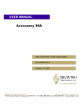
www.mgeups.com
Pulsar Evolution
2200/3000/3000 XL
Installation and user
manual
MGE UPS Systems
1660 Scenic Avenue
Costa Mesa, CA 92626
(714) 557-1636
For service call
1-800-438-7373
www.mgeups.com
IMPORTANT SAFETY INSTRUCTIONS
Read before installing product
SAVE THESE INSTRUCTIONS. This manual contains important instructions for 89347, 89348, and 89349 that should
be followed during installation and maintenance of the UPS and batteries.
Thank you for selecting an MGE UPS SYSTEMS product to protect your electrical equipment.
The Pulsar Evolution range has been designed with the utmost care. We recommend that you take the time to read this manual to take full advantage of the many features of your UPS.
MGE UPS SYSTEMS pays great attention to the environmental impact of its products. Measures that have made Pulsar
Evolution a reference in environmental protection include:
◗ The eco-design approach used in product development,
◗ recycling of Pulsar Evolution at the end of its service life.
To discover the entire range of MGE UPS SYSTEMS products and the options available for the Pulsar Evolution range, we
invite you to visit our web site at www.mgeups.com or contact your MGE UPS SYSTEMS representative.
This manual contains important instructions for Pulsar Evolution Models that must be followed during installation, operation
and maintenance of the UPS and batteries.
The Pulsar Evolution UPS Models that are covered in this manual are listed below.
Pulsar Evolution 2200, 3000, 3000XL
The normal battery voltage for all models is as follows:
Pulsar Evolution 2200-72V, 3000-72V
The Pulsar Evolution UPS is intended for installation in a temperature within 0 to 40º C, free of conductive contaminant’s.
This equipment has been tested and found to comply with the limits for a Class A digital device, pursuant to Part 15 of the
FCC Rules. These limits are designed to provide reasonable protection against harmful interference when the equipment is
operated in a commercial environment. This equipment generates, uses, and can radiate radio frequency energy and, if not
installed and used in accordance with the instruction manual, may cause harmful interference to radio communications.
Operation of this equipment in a residential area is likely to cause harmful interference in which case the user will be required
to correct the interference at his own expense.
Note
Page 2 -
3400723100/AD
Introduction
CAUTION: Safety of persons
◗
The UPS has its own internal power source (the battery). Consequently, the power outlets may be energized even if the UPS is
disconnected from the AC-power source.
◗ Dangerous voltage levels are present within the UPS. It should be opened exclusively by qualified service personnel.
◗ The UPS must be properly earthed. Measurements are required to ensure that the total leakage current of the UPS and the
protected equipment does not exceed 3.5 mA by checking their characteristics (maximum leakage current of the UPS = 2 mA).
◗ The battery supplied with the UPS contains small amounts of toxic materials. To avoid accidents, the directives listed below
must be observed:
- Never burn the battery (risk of explosion).
- Do not attempt to open the battery (the electrolyte is dangerous for the eyes and skin).
- Comply with all applicable regulations for the disposal of the battery.
- Batteries constitute a danger (electrical shock, burns). The short-circuit current may be very high. Precautions must be
taken for all handling: remove watches, rings, bracelets and any other metal objects, use tools with insulated handles.
- Do not lay tools or metal parts on top of batteries.
CAUTION: Product safety
◗
◗
◗
◗
◗
◗
◗
◗
◗
The UPS connection instructions and operation described in the manual must be followed in the indicated order.
UPS must be connected to a nearby wall outlet that is easily accessible. The UPS can be disconnected from the AC-power
source by removing the power cord.
Check that the indications on the rating plate correspond to your AC-power system and to the actual electrical consumption of
all the equipment to be connected to the UPS.
Never install the UPS near liquids or in an excessively damp environment.
Never let a foreign body penetrate inside the UPS.
Never block the ventilation grates of the UPS.
Never expose the UPS to direct sunlight or source of heat.
If the UPS must be stored prior to installation, storage must be in a dry place.
The admissible storage temperature range is -25ºC to +55ºC.
Special precautions
◗
◗
◗
All handling operations will require at least two people (unpacking, installation in rack system).
Once installed and connected to the AC power source for the first time, the battery will start to charge. Full charging to obtain
the rated battery backup time requires at least 8 hours.
Before and after the installation, if the UPS remains de-energized for a long period, the UPS must be energized for a period of
24 hours, at least once every 6 months (for a normal storage temperature less than 25°C). This charges the battery, thus
avoiding possible irreversible damage. During the replacement of the battery module, it is imperative to use the same type and
number of element previously mounted in the UPS, in order to maintain an identical level of performance and safety. In case of
doubt, don’t hesitate to contact our after sales department (for more information, refer to the web site www.mgeups.com).
3400723100/AD
- Page 3
Foreword
Using this document
Information may be found in two ways, using:
◗ the contents;
◗ the index.
Pictograms
IMPORTANT: Important instructions that must always be followed.
NOTE: Information, advice, help.
WARNING: Indicates present eminent danger, precautionary action required.
CAUTION: Indicates to proceed with caution, precautionary action required.
Visual indication.
Action.
Audio indication.
In the illustrations on the following pages, the symbols below are used:
LED off.
LED on.
LED flashing.
Page 4 -
3400723100/AD
Contents
1.
Presentation
1.1
Overall view .................................................................................................................................. 7
Tower position ..................................................................................................................................7
Rack position....................................................................................................................................7
2.
3.
1.2
Back .............................................................................................................................................. 8
1.3
Control panel ..................................................................................................................................9
Installation
2.1
Unpacking and parts check ......................................................................................................10
2.2
Upright installation (tower position) ..........................................................................................11
2.3
Flat installation (rack position) ..................................................................................................12
2.4
Connecting the protected equipment ........................................................................................13
2.5
Connection to the RS232 or USB communications port (optional) ........................................14
2.6
Connection to the data-line protection port (optional)..............................................................14
2.7
Installation of the communications-card option ......................................................................15
Operation
3.1
Start-up..........................................................................................................................................16
3.2
Shift to booster or fader mode (during voltage variations in the AC-input power) ....................16
3.3
Operation on battery power (following failure of AC-input power) ............................................17
Transfer to battery power ..............................................................................................................17
Threshold for the low-battery warning............................................................................................17
3.4
Personalization (optional) ............................................................................................................18
Function..........................................................................................................................................18
ON / OFF conditions tab ................................................................................................................18
Battery tab ......................................................................................................................................18
Voltage-thresholds tab ..................................................................................................................19
Sensitivity tab ................................................................................................................................19
4.
5.
Maintenance
4.1
Trouble-shooting ..........................................................................................................................20
4.2
Replacement of the battery module ..........................................................................................21
Environment ....................................................................................................................................23
3400723100/AD
- Page 5
Contents
6.
Appendices
6.1
Technical data ..............................................................................................................................24
Simplified diagram..........................................................................................................................24
Technical characteristics ................................................................................................................25
Examples of battery backup times ................................................................................................26
Page 6 -
3400723100/AD
6.2
Glossary ........................................................................................................................................27
6.3
Index ..............................................................................................................................................28
1. Presentation
1.1 Overall view
Tower position
Dimensions in inches
(W x H x D)
Evolution 2200
Evolution 3000
17.24 (19") x 3.56 (2U) x 25.2
Evolution 3000 XL
Weight in lbs
Evolution 2200
75
Evolution 3000
82
Evolution 3000 XL
46
SAR
P U Lut io n
Ev ol 0
300
Rack position
D
H
SAR
P U L tion
E v o l u0
300
W
3400723100/AD
- Page 7
1. Presentation
1.2 Back
Pulsar Evolution 2200
1
USB communications port.
2
RS232 communications port.
3
Connector for automatic detection of an
additional battery module.
4
Data-line protection.
5
Slot for communications-card option.
6
Connector for an additional battery
module.
7
Output circuit breakers.
8
Six receptacles for direct connection of
protected equipment.
9
Two programmable receptacles (1 and 2).
1
Data line protection
R
IN
1
Programmable
RS232
34Z5
U.P.S.
2
OUT
AC Input
WARNING
3 battery cabinets max
BATTERY CONNECTOR
Volt: 72Vdc
40A
72Vdc, 7Ah
TO BATTERY
CABINET
344-50282-00
Pb
AC Input
Volt 120V~1O
Amps 16A MAX
Hertz 50/60 Hz
AC Output
Volt 120V~1O
Hertz 50/60 Hz
W/VA 1540W/1920VA
U.S. PAT. No. 6,094,363
2
Programmable
SITE WIRING
FAULT
AC Output
5-20P
1
2
3
5
4
6
8
9
10
Pulsar Evolution 3000 / 3000 XL
A
1
Data line protection
R
WARNING
3 battery cabinets
max for 3000
12 battery cabinets
max for 3000XL
BATTERY CONNECTOR
Volt: 72Vdc
40A
72Vdc, 9Ah
TO BATTERY
CABINET
Only for 3000
344-50297-00
Pb
AC Input
Volt 120V~1O
Amps 24A MAX
Hertz 50/60 Hz
AC Output
Volt 120V~1O
Hertz 50/60 Hz
W/VA 2000W/2800VA for 3000
2000W/2568VA for 3000 XL
U.S. PAT. No. 6,094,363
A
2
Programmable
1
34Z5
U.P.S.
AC Input
2
B
SITE WIRING
FAULT
1/2
OUT
Programmable
RS232
AC OUTPUT BRANCH PROTECTOR (15Amp max/plug)
B
IN
AC Output
L5-30
5-3
0P
1
2
3
5
6
4
7
8
9
10
10 Input power cords for connection to
AC-power source; 2200/5-20P and
3000/L5-30.
11 Battery module connectors (to the UPS
or to other battery modules).
EXB additional battery module
11
3
11
13
12 Connectors for automatic detection of
additional battery modules.
13 Circuit breaker for battery ON/OFF and
protection.
Page 8 -
3400723100/AD
1. Presentation
1.3 Control panel
15 Illuminated ON/OFF button for the receptacles.
16 Operation on battery power.
17
UPS fault.
Battery fault.
18 Overload.
19 Group 1 programmable receptacles supplied with power.
1
2
20 Group 2 programmable receptacles supplied with power.
21 Booster or fader mode.
%
22 Bar graph indicating percent load at output.
%
23 Bar graph indicating the battery charge level.
76 to 100%.
51 to 75%.
26 to 50%.
0 to 25%.
3400723100/AD
- Page 9
2. Installation
2.1 Unpacking and parts check
26
25
27
28
29
30
31
SAR
P U Lut io n
Ev ol 0
300
32
26 RS232 communications cable for Windows Operating Systems. For UNIX/Linux Operating Systems, please order, for
free, the following part number: 66090
27 USB communications cable.
28 Telescopic rails for mounting in 19" bay with mounting hardware.
29 Two securing systems for equipment power cords.
30 CD-ROM with the Solution-Pac and UPS Driver software.
31 Product documentation.
32 Two supports for the upright position.
Page 10 -
3400723100/AD
2. Installation
2.2 Upright installation (tower position)
Connect the two supports for the upright position.
P U L S A R
Evolution
3 0 0 0
SAR
P U Lut io n
Ev ol 0
300
3400723100/AD
- Page 11
SAR
P U L tion
E v o l u0
300
2. Installation
2.4 Connecting the protected equipment
CAUTION: Check that the indications on the rating plate on the back of the UPS correspond to your AC-power
system and to the actual electrical consumption of all the equipment to be connected to the UPS.
BATTERY CONNECTOR
Volt: 72Vdc
40A
U.S. PAT. No. 6,094,363
1 - Remove the power cord supplying the
equipment to be protected.
- Pulsar Evolution 2200/3000/3000 XL:
Connect the supplied input power cord 10
to the AC power wall receptacle.
AC Output
AC Input
Volt 120V~1O
Hertz 50/60 Hz
W/VA 1540W/1920VA
Volt 120V~1O
Amps 16A MAX
Hertz 50/60 Hz
360°
Rotation Plug
2
Programmable
9
1
Programmable
8
2
1
AC Output
29
AC Input
R
34Z5
U.P.S.
25
10
2 - Connect the protected equipment to the
UPS using the rotation power cord 25 . It
is advised to connect priority loads to the
four standard receptacles 8 and any nonpriority loads to the two programmable
receptacles 9 .
If the UPS is connected to a computer running MGE communications software, it is possible to program the interruption of power to
the programmable receptacles 9
during operation on battery power,
thus reserving backup power for
the priority loads.
3 - Lock the connections using the securing
system 29 .
As soon as the UPS is energized, the
battery begins charging. Eight hours are
required to charge to the full rated backup time.
NOTE: Pulsar Evolution 3000 XL: At least one EXB additional battery module must be connected to the UPS because it
does not have internal batteries. See the EXB battery-module installation manual (Doc. no. 3400711600) for information
on making the connections.
3400723100/AD
- Page 13
2. Installation
2.5 Connection to the RS232 or USB communications port (optional)
CAUTION: The RS232 and USB
communications ports cannot
operate simultaneously.
26
1 - Connect the RS232 26 or USB 27
communications cable to the serial port or
the USB port on the computer.
27
RS232
TO BATTERY
CABINET
2
1
344-50297-00
2 - Connect the other end of the communications cable 26 or 27 to the RS232 2
or USB 1 communications port on the
UPS.
IN
OUT
WARNING
Data line protection
SITE WIRING
FAULT
72Vdc, 9Ah
Only for 3000
3 battery cabinets
max for 3000
12 battery cabinets
max for 3000XL
Pb
The UPS can now communicate with all
MGE UPS SYSTEMS supervision, set-up or
safety software.
2.6 Connection to the data-line protection port (optional)
RS232
The data-line protection function on the UPS
eliminates overvoltage flowing on the computer-network lines.
Simply connect the line to be protected to
the UPS using the data-line protection connectors (IN and OUT) as indicated opposite
(RJ45 cables not supplied).
TO BATTERY
CABINET
344-50297-00
IN
OUT
WARNING
Data line protection
SITE WIRING
FAULT
72Vdc, 9Ah
Only for 3000
BATTERY CONNECTOR
Volt: 72Vdc
40A
U.S. PAT. No. 6,094,363
3400723100/AD
3 battery cabinets
max for 3000
12 battery cabinets
max for 3000XL
Pb
Page 14 -
2. Installation
2.7 Installation of the communications-card option
RS232
1 - Remove the slot cover 5 secured by
two screws.
TO BATTERY
CABINET
2 - Insert the card in the slot.
5
344-50297-00
It is not necessary to shut down the UPS to
install the communications card.
IN
OUT
WARNING
72Vdc, 9Ah
Only for 3000
3 battery cabinets
max for 3000
12 battery cabinets
max for 3000XL
Pb
Data line protection
SITE WIRING
FAULT
Slot for the communications-card
option.
3 - Secure the cover with the two screws.
3400723100/AD
- Page 15
3. Operation
3.1 Start-up
15
16
17
1
%
Page 16 -
3400723100/AD
2
%
Press the ON / OFF button 15 .
The buzzer beeps and all the LEDs come ON.
The buzzer beeps twice during the self-test, then button 15 remains
ON, indicating that the receptacles are supplied with power.
- AC power is present: Only button 15 is ON. The protected equipment is supplied by the AC-power source.
- AC power is absent: Button 15 and LED 16 are ON. The protected
equipment is supplied by the UPS, operating on battery power.
All the connected equipment is supplied with power.
3. Operation
3.3 Operation on battery power (following failure of AC-input power)
Transfer to battery power
The AC-input power is out of tolerances, LED 16 goes ON.
During operation on battery power, the buzzer beeps every ten seconds.
The equipment connected to the UPS is supplied by the battery.
16
1
2
%
%
Threshold for the low-battery warning
When the threshold is reached, the buzzer beeps every three seconds.
The low-battery warning threshold can be set by the user, with the “UPS
Driver” software.
16
1
%
There is very little remaining battery backup time. Close all applications because UPS automatic shutdown is imminent.
When the battery reaches the end of its backup time, the UPS shuts
down and all the LEDs go OFF.
2
%
The equipment is no longer supplied with power.
The UPS automatically restarts when power returns.
NOTE: If the UPS does not restart, check that the “automatic restart when power returns” function has not been disabled
(see section 3.4 Personalization).
3400723100/AD
- Page 17
3. Operation
3.4 Personalization (optional)
Function
Personalization parameters can be set and modified using the UPS Driver software installed on a computer that is connected to the UPS (see section 2.5 Connection to the RS232 or USB communications port).
Check that the RS232 26 communications cable is connected.
UPS Driver installation:
1 - Insert the Solution-Pac CD-ROM containing the UPS Driver software in the drive of a PC running Windows.
2 - Open the Windows File manager or Explorer and select the CD-ROM drive.
3 - Double-click "\Emb\Evolutio\Config\Setup.exe".
Once UPS Driver has been installed, UPS parameters can be modified in a window containing a number of tabs, each
presenting a set of parameters :
Configurable function
Default setting
Automatic restart
Enabled
Cold start
Enabled
Forced reboot
Enabled
Energy saving
Disabled
UPS ON / OFF via software
Enabled
Configurable function
Default setting
Options
Once a week
Every day
Once a month
No test
Battery tab
Interval between automatic battery tests
Low-battery warning threshold
Page 18 -
3400723100/AD
20% of the remaining battery back- 10 to 40% of the remaining battery
backup time
up time
Configuration of additional battery modules
Display the number of standard
EXB modules connected
to the UPS
Protection against deep discharges
Enabled
3. Operation
Voltage-thresholds tab
Configurable function
Default setting
Options
Output voltage on battery power
120 V
100 V - 127 V
Upper threshold for transfer to battery power
151 V
141 V to 153 V
Fader-mode cut-in threshold
132 V
127 V to 138 V
Booster-mode cut-in threshold
102 V
92 V to 108 V
Lower threshold for transfer to battery power
89 V
80 V to 94 V
Maximum input-voltage range
Disabled
Enabled
(1) Lower threshold for transfer to battery mode = 70 V
Sensitivity tab
Configurable function
Default setting
Options
UPS sensitivity level
Normal
High or low
NOTE: For more information about these settings, refer to the Help function of the "UPS Driver" software.
3400723100/AD
- Page 19
4. Maintenance
4.1 Trouble-shooting
Troubleshooting not requiring MGE UPS SYSTEMS after-sales support (all versions)
Indication
Signification
Correction
LED 18 flashes and the
buzzer beeps once.
UPS overload. The power drawn by the connected
equipment exceeds UPS capacity.
Check the power drawn by the
equipment and disconnect any
non-priority devices.
LED 17 flashes.
A battery fault was detected during the automatic battery test.
Replace the battery module
(see section 4.2).
Troubleshooting requiring MGE UPS SYSTEMS after-sales support
Indication
LED 17 goes ON and
the buzzer sounds
continuously.
Signification
The equipment connected to the UPS is no
longer protected.
Page 20 -
3400723100/AD
Correction
UPS electronics have detected a UPS fault.
◗ The connected equipment is no longer supplied.
Call the after-sales support
department.
3400723100/AD
- Page 21
4. Maintenance
F - Remove the screw securing the battery
cover.
G - Remove the cover.
F
G
H - Disconnect the battery module.
I - Remove the battery module.
H
I
Battery Replacement Chart
Component
Manufacturer
12V 7Ah (in 2200VA)
12V 7Ah (in 3000VA )
Panasonic
Panasonic
Manufacturer’s
Catalog Number
LC-R127
LC-R129
Installation of the new battery module
Carry out the above operation in reverse order.
CAUTION: risk of electric arc when connecting the battery.
To maintain an identical level of performance and safety, use a battery module identical to that previously
mounted in the UPS.
◗ Press the two parts of the battery connector tightly together to ensure proper connection.
◗
◗
Page 22 -
3400723100/AD
5. Environment
This product has been designed to respect the environment:
It does not contain CFCs or HCFCs.
UPS recycling at the end of service life:
MGE UPS SYSTEMS undertakes to recycle, by certified companies and in compliance with all applicable regulations, all
UPS products recovered at the end of their service life (contact your MGE branch office).
Packing:
UPS packing materials must be recycled in compliance with all applicable regulations.
WARNING:
This product contains lead-acid batteries. Lead is a dangerous substance for the environment if it is not properly recycled
by specialized companies.
Web site: www.mgeups.com
3400723100/AD
- Page 23
6. Appendices
6.1 Technical data
Simplified diagram
Filter
Booster / fader transformer
Input
Output
Inverter
Charger
Battery
Page 24 -
3400723100/AD
6. Appendices
Technical characteristics
Output rating
AC-input power
◗ Voltage
◗ Frequency
Output power (operation
on battery power)
◗ Voltage
◗ Frequency
Battery
Environment
Noise level (operation on
AC-input power)
◗ Operating temperature
◗ Relative humidity
◗
Pulsar Evolution 2200
Pulsar Evolution 3000
Pulsar Evolution 3000 XL
1920 VA / 1540 W (1)
2880 VA / 2000 W
2568 VA / 2000 W
Single phase, 80 V to 153 V (1)
47 Hz to 70 Hz (50 Hz system) or 56.5 Hz to 70 Hz (2) (60 Hz system)
Single-phase, 120 V (3) (+ 6% / - 10%)
50/60 Hz +/- 1 Hz
6 x 12 V, 7 Ah, sealed leadacid, maintenance free
6 x 12 V, 9 Ah, sealed
lead-acid, maintenance free
external
<40 dBA
0 to 40° C
20 to 90% (without condensation)
(1) The upper and lower thresholds may be set using the UPS Driver software.
(2) Or 40 Hz in low-sensitivity mode (may be set using the UPS Driver software).
(3) Adjustable from 100 to 127 V using the UPS Driver software.
3400723100/AD
- Page 25
6. Appendices
Examples of battery backup times
Pulsar Evolution 2200
1 data server
+ 1 hard disk
2 distributed servers
+ 1 hub
8 rack-mounted servers
0
5
10
15
20
25
30 t (min)
0
5
10
15
20
25
30
Pulsar Evolution 3000
1 data server
+ 1 hard disk
4 distributed servers
+ 1 hub + 1 router
12 rack-mounted servers
35
t (min)
Pulsar Evolution 3000 XL + 3 EXB
1 telecom device
1 set of telecom devices
1 large set of telecom
devices
0
Page 26 -
3400723100/AD
100
200
300
400
500
t (min)
6. Appendices
6.2 Glossary
Backup time
Time that the connected equipment can operate on battery power if AC-input power
fails.
Bar graph
Device on the front panel indicating the percent remaining backup time or the percent
load.
Battery module (additional)
Additional battery modules connected in parallel to increase the UPS backup time.
Booster mode
Automatic UPS operating mode whereby the input-power voltage is increased if it drops
below a value set in the personalization parameters, thus avoiding a battery discharge.
De-energized
The UPS must be physically disconnected from the AC-input power.
Equipment
Devices and systems connected to the UPS output.
Fader mode
Automatic UPS operating mode whereby the input-power voltage is decreased if it rises
above a value set in the personalization parameters, thus avoiding a battery discharge.
Input circuit breaker
Circuit breaker protecting the upstream distribution system against UPS faults.
Output circuit breaker
Circuit breaker protecting the UPS against high overloads or faults on the connected
equipment.
Personalization
The parameters for a number of UPS functions may be modified using the UPS Driver
software to adapt UPS operation to user needs.
RS232 communications port
For UPS connection to a computer via the serial port.
Programmable receptacles
Pulsar Evolution has two programmable receptacles. They may be used for sequential
start-up of protected equipment, shedding of non-critical loads during operation on
battery power or management of operating priorities to provide the most critical devices
with more backup time before battery power runs out. These receptacles may be
programmed using the Solution-Pac software on the CD-ROM supplied with the UPS.
Receptacles
Receptacle that allows you to connect the equipment you want to protect.
Solution-Pac
MGE UPS SYSTEMS safety, set-up and supervision software suite on the CD-ROM
supplied with the UPS.
UPS
Uninterruptible Power Supply.
UPS Driver
Communications software on the CD-ROM supplied with the UPS. It may be used to
personalize the default settings.
USB communications port
For UPS connection to a computer via the USB port.
3400723100/AD
- Page 27
6. Appendices
6.3 Index
A
Automatic start ................................................................18
B
Bar graph ..........................................................................9
Battery
Additional modules ....................................................8
Backup time ............................................................26
End of backup time..................................................17
Fault ..........................................................................9
Personalization ........................................................18
Recycling ................................................................23
Replacement......................................................21, 22
Threshold for low-battery warning ..........................17
Transfer to battery power ....................................9, 17
Buttons ..............................................................................9
Buzzer ............................................................................17
C
Circuit breakers
Battery circuit breaker................................................8
Input circuit breaker ..................................................8
Output circuit breaker ................................................8
Communication
Cards ..................................................................8, 15
Ports ....................................................................8, 14
Connections
Data-line protection..................................................14
RS232 communications port ..................................14
USB communications port ......................................14
M
Mode
Booster mode ......................................................9, 16
Fader mode ........................................................9, 16
Sleep mode (automatic start) ..................................18
O
Overloads ....................................................................9, 20
P
Personalization ..............................................................18
Battery ....................................................................18
ON / OFF conditions ..............................................18
Output......................................................................19
Ports
RS232 ................................................................8, 14
USB ....................................................................8, 14
Programmable receptacles ..........................................8, 9
S
Safety..............................................................................21
Start-up ..........................................................................16
T
Technical characteristics ................................................25
Temperature (excessive ambient) ..................................25
U
UPS Driver....................................................16, 17, 18, 25
UPS ON / OFF via software ..........................................18
D
Dimensions........................................................................7
W
E
Web site ..........................................................................23
Weight ..............................................................................7
Environment ....................................................................23
F
Fault (UPS)........................................................................9
L
LEDs..................................................................................9
Page 28 -
3400723100/AD
1660 Scenic Avenue
Costa Mesa, CA 92626
USA
www.mgeups.com