1
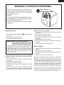
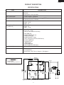
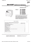
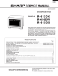
R-120DG
R-120DP
R-120DSC
SUPPLEMENTAL SERVICE MANUAL
S5012R120DPG/
MICROWAVE OVEN
MODEL
START/MIN
UTE
LUS
STOP/CLEA
ON DEF
LBS QTY
CHECK
R
HALF
R-120DG
R-120DP
R-120DSC
PINT
In the interest of user-safety the oven should be restored to its original
condition and only parts identical to those specified should be used.
WARNING TO SERVICE PERSONNEL: Microwave ovens contain circuitry capable of producing very high voltage and
current, contact with following parts may result in a severe,
possibly fatal, electrical shock. (High Voltage Capacitor, High
Voltage Power Transformer, Magnetron, High Voltage Rectifier
Assembly, High Voltage Harness etc..)
This is a supplemental Service Manual for Models R-120DG, R-120DP, R-120DSC. This model is
quite similar to base model R-120DW. Use this supplemental manual together with the Base Model Service Manual
(Refer No. is S3007R120DPW/) for complete operation, service information, etc..
TABLE OF CONTENTS
Page
PRECAUTIONS TO BE OBSERVED BEFORE AND DURING SERVICING TO
AVOID POSSIBLE EXPOSURE TO EXCESSIVE MICROWAVE ENERGY ................... INSIDE FRONT COVER
BEFORE SERVICING ...................................................................................................... INSIDE FRONT COVER
WARNING TO SERVICE PERSONNEL ................................................................................................................ 1
FOREWORD AND WARNING ............................................................................................................................... 2
PRODUCT DESCRIPTION .................................................................................................................................... 3
PICTORIAL DIAGRAM .......................................................................................................................................... 4
PARTS LIST .......................................................................................................................................................... 5
PACKING AND ACCESSORIES ........................................................................................................................... 9
SHARP CORPORATION
This document has been published to be used for after
sales service only.
The contents are subject to change without notice.
R-120DG
R-120DP
R-120DSC
PRECAUTIONS TO BE OBSERVED BEFORE AND
DURING SERVICING TO AVOID POSSIBLE
EXPOSURE TO EXCESSIVE MICROWAVE
ENERGY
(a) Do not operate or allow the oven to be operated with the door open.
(b) Make the following safety checks on all ovens to be serviced before activating the magnetron or other
microwave source, and make repairs as necessary: (1) interlock operation, (2) proper door closing, (3)
seal and sealing surfaces (arcing, wear, and other damage), (4) damage to or loosening of hinges and
latches, (5) evidence of dropping or abuse.
(c) Before turning on microwave power for any service test or inspection within the microwave generating
compartments, check the magnetron, wave guide or transmission line, and cavity for proper alignment,
integrity, and connections.
(d) Any defective or misadjusted components in the interlock, monitor, door seal, and microwave
generation and transmission systems shall be repaired, replaced, or adjusted by procedures described
in this manual before the oven is released to the owner.
(e) A microwave leakage check to verify compliance with the Federal Performance Standard should be
performed on each oven prior to release to the owner.
BEFORE SERVICING
Before servicing an operative unit, perform a microwave emission check as per the Microwave
Measurement Procedure outlined in this service manual.
If microwave emissions level is in excess of the specified limit, contact SHARP ELECTRONICS
CORPORATION immediately @1-800-237-4277.
If the unit operates with the door open, service person should 1) tell the user not to operate the oven
and 2) contact SHARP ELECTRONICS CORPORATION and The Food and Drug Administration's
Center for Devices and Radiological Health immediately.
Service personnel should inform SHARP ELECTRONICS CORPORATION of any certified unit found
with emissions in excess of 4mW/cm 2. The owner of the unit should be instructed not to use the unit
until the oven has been brought into compliance.
R-120DG
R-120DP
R-120DSC
WARNING TO SERVICE PERSONNEL
Microwave ovens contain circuitry capable of producing very high voltage and current, contact with
following parts may result in a severe, possibly
fatal, electrical shock.
(Example)
High Voltage Capacitor, High Voltage Power Transformer, Magnetron, High Voltage Rectifier Assembly, High Voltage Harness etc..
Read the Service Manual carefully and follow all
instructions.
Don't Touch !
Danger High Voltage
When the testing is completed,
1. Disconnect the power supply cord, and then remove
outer case.
2. Open the door and block it open.
3. Discharge high voltage capacitor.
4. Reconnect the leads to the primary of the power
transformer.
5. Reinstall the outer case (cabinet).
6. Reconnect the power supply cord after the outer case is
installed.
7. Run the oven and check all functions.
Before Servicing
1. Disconnect the power supply cord ¬, and then remove
outer case.
2. Open the door and block it open.
3. Discharge high voltage capacitor.
WARNING:RISK OF ELECTRIC SHOCK.
DISCHARGE THE HIGH-VOLTAGE
CAPACITOR BEFORE SERVICING.
The high-voltage capacitor remains charged about 60
seconds after the oven has been switched off. Wait for 60
seconds and then short-circuit the connection of the highvoltage capacitor (that is the connecting lead of the highvoltage rectifier) against the chassis with the use of an
insulated screwdriver.
After repairing
1. Reconnect all leads removed from components during
testing.
2. Reinstall the outer case (cabinet).
3. Reconnect the power supply cord after the outer case is
installed.
4. Run the oven and check all functions.
Whenever troubleshooting is performed the power supply
must be disconnected. It may, in some cases, be necessary
to connect the power supply after the outer case has been
removed, in this event,
1. Disconnect the power supply cord, and then remove
outer case.
2. Open the door and block it open.
3. Discharge high voltage capacitor.
4. Disconnect the leads to the primary of the power
transformer.
5. Ensure that the leads remain isolated from other
components and oven chassis by using insulation tape.
6. After that procedure, reconnect the power supply cord.
Microwave ovens should not be run empty. To test for the
presence of microwave energy within a cavity, place a cup
of cold water on the oven turntable, close the door and set
the power to HIGH and set the microwave timer for two (2)
minutes. When the two minutes has elapsed (timer at zero)
carefully check that the water is now hot. If the water
remains cold carry out Before Servicing procedure and reexamine the connections to the component being tested.
When all service work is completed and the oven is fully
assembled, the microwave power output should be checked
and a microwave leakage test should be carried out.
1
R-120DG
R-120DP
R-120DSC
SERVICE MANUAL
MICROWAVE OVEN
R-120DG/ R-120DP/ R-120DSC
FOREWORD
This Manual has been prepared to provide Sharp Electronics Corp. Service Personnel with Operation and Service
Information for the SHARP MICROWAVE OVEN, R-120DG, R-120DP, R-120DSC.
The models R-120DG, R-120DP and R-120DSC are quite similar to base model R-120DW (Refer No. is S3007R120DPW/).
It is recommended that service personnel carefully study the entire text of this manual and the base model's manual so that
they will be qualified to render satisfactory customer service.
Check the interlock switches and the door seal carefully. Special attention should be given to avoid electrical shock and
microwave radiation hazard.
WARNING
Never operate the oven until the following points are ensured.
(A) The door is tightly closed.
(B) The door brackets and hinges are not defective.
(C) The door packing is not damaged.
(D) The door is not deformed or warped.
(E) There is no other visible damage with the oven.
Servicing and repair work must be carried out only by trained service personnel.
DANGER
Certain initial parts are intentionally not grounded and present a risk of electrical shock only during servicing.
Service personnel - Do not contact the following parts while the appliance is energized;
High Voltage Capacitor, Power Transformer, Magnetron, High Voltage Rectifier Assembly, High Voltage
Harness;
If provided, Vent Hood, Fan assembly, Cooling Fan Motor.
All the parts marked “*” on parts list are used at voltages more than 250V.
Removal of the outer wrap gives access to voltage above 250V.
All the parts marked “∆” on parts list may cause undue microwave exposure, by themselves, or when they are damaged,
loosened or removed.
SHARP ELECTRONICS CORPORATION
SHARP PLAZA, MAHWAH,
NEW JERSEY 07430-2135
2
R-120DG
R-120DP
R-120DSC
PRODUCT DESCRIPTION
SPECIFICATIONS
ITEM
DESCRIPTION
Power Requirements
120 Volts
60 Hertz
Single phase, 3 wire grounded
1030W / Approx. 9 Amperes
Power Consumption
Power Output
600 W nominal of RF microwave energy (IEC Test procedure)
Operating frequency 2450 MHz
Width 14-3/8"
Height 14-1/8"
Depth 14"
Width 11-3/4"
Height 16"
Depth 11-7/8"
Case Dimensions
Cooking Cavity Dimensions
(0.7 Cubic feet)
Control Complement
Touch Control System
Clock (1:00 - 12:59)
Timer (0 - 99 minutes 45 seconds)
POPCORN pad
EXPRESS DEFROST pad
COMPU COOK pad
DOUBLE QUANTITY pad
STOP/ CLEAR pad (STOP/CLEAR button)
CLOCK/ TIMER pad
10 MINUTES pad
1 MINUTE pad
15 SECONDS pad
START/ MINUTE PLUS button
Yes
Oven Cavity Light
Safety Standard
UL Listed.
FCC Authorized
DHHS Rules, CFR, Title 21, Chapter 1, Subchapter J
C/T FUSE
MAGNETRON
THERMAL CUT-OUT
SCHEMATIC
NOTE: CONDITION OF OVEN
1. DOOR CLOSED
2. CLOCK APPEARS ON DISPLAY
COM.
POWER
TRANSFORMER
N.O.
(RY-2)
(RY-1)
A3
PRIMARY
INTERLOCK
RELAY
CAPACITOR
0.72µF
CONTROL UNIT
A1
B2
B1
GRN
120V AC
60 Hz
DOOR
SENSING
SWITCH
TTM
OL
FM
MONITOR
SWITCH
RECTIFIER
MAGNETRON
TURNTABLE
MOTOR
OVEN
LAMP
FAN
MOTOR
SECONDARY
INTERLOCK
SWITCH
Figure O-1. Oven Schematic-Off Condition
3
H
1
2
BLK
3
4
4
N.O.
5
WHT
WHT
E
Figure S-1. Pictorial Diagram
BLU
RED
RED
OVEN LAMP
& SOCKET
BLK
RED
WHT
BLK
NOTE:
The neutral (WHT) wire must be
connected to the terminal with "N"
mark on the power supply cord.
POWER SUPPLY CORD
120V 60Hz
H.V.
RECTIFIER
POWER
TRANSFORMER
HIGH VOLTAGE
WIRE
MAGNETRON
HIGH
VOLTAGE
CAPACITOR
5
GRY
GRY
RED
N
HIGH VOLTAGE COMPONENTS
MAGNETRON
THERMAL CUT-OUT
BLK
GRD
A
GRY
GRY
TURNTABLE
MOTOR
WHT
GRY
RED
RED
WHT
RED
Blue Mark
C
COM
BLU
GRY
FAN MOTOR
C/T FUSE
BLK
NOTE: Hot (RED) wire must
be connected to the terminal
with blue mark on the oven
light socket.
NOTE:
The grounding conductor of
the power supply cord has
been grounded by power
supply cord fixing screw.
The screw must always be
kept tight.
4
SECONDARY
INTERLOCK SWITCH
COM
GRY
GRN
RED
CN-B
SP
2
3
MONITOR
SWITCH
N.C.
COM
N.O.
DOOR
SENSING SWITCH
RY2
GRN
GRN
RY1
PRIMARY
INTERLOCK
RELAY
1
D
3 WHT
2
1 RED
3
B
CN-A
1
CN-A
BLK
2
CN-B
2 GRY
1 GRN
To fan duct
G
RED
1
H
F
CONTROL PANEL
R-120DG
R-120DP
R-120DSC
6
A
6
B
C
D
E
F
G
H
R-120DG
R-120DP
R-120DSC
PARTS LIST
Note: The parts marked “ ∆” may cause undue microwave exposure.
The parts marked “*” are used in voltage more than 250V.
REF. NO.
PART NO.
DESCRIPTION
1- 1
1- 2
1- 3
1- 4
1- 5
1- 6
1- 7
1- 8
1- 8
1- 9
1-10
1-10
1-11
1-12
QSW-MA137WRE0
FFS-BA027WRKZ
FACCDA079WRE0
QSOCLA021WRE0
FH-DZA095WRKZ
RC-QZA209WRE0
RMOTEA383WRE0
RV-MZA195WRE0
RV-MZA198WRE0
RLMPTA068WRE0
RMOTDA211WRE0
RMOTDA186WRE0
RTHM-A117WRE0
RTRN-A606WRZZ
Secondary interlock switch & door sensing switch
C/T fuse (120˚C, 13A) & monitor switch (AM51620C53Y1) assembly
Power supply cord
Oven lamp socket
High voltage rectifier
High voltage capacitor
Fan motor
Magnetron
Magnetron (Iinterchangeable)
Oven lamp
Turntable motor
Turntable motor (Iinterchangeable)
Thermal cut-out 95˚C
Power transformer
22222-
GCABUA779WRPZ
GCABUA781WRPZ
GCABUA783WRPZ
GDAI-A325WRWZ
GLEGPA074WRE0
Outer case cabinet [R-120DSC]
Outer case cabinet [R-120DG]
Outer case cabinet [R-120DP]
Bottom plate
Foot
Q'TY
CODE
2
1
1
1
1
1
1
1
1
1
1
1
1
1
AH
AS
AF
AH
AQ
AX
AV
BK
BN
AG
AS
AW
AQ
BM
1
1
1
1
2
BB
BB
BB
AF
AC
1
1
1
1
1
BB
AY
AN
AM
AF
1
1
1
1
1
1
1
1
1
1
1
1
1
1
1
1
2
1
1
1
1
1
1
1
1
1
1
1
1
1
1
1
1
1
1
1
AH
AD
AD
AF
AD
AC
AE
AL
AC
AD
-AD
AE
AE
AE
AE
AC
AG
AC
AC
AC
AC
AF
AE
AD
AE
AB
AC
AC
AE
AB
AC
AC
AC
AC
AC
ELECTRIC PARTS
*
*
*∆
*∆
*
CABINET PARTS
1
1
1
2
3
CONTROL PANEL PARTS
33333-
1
2
2-1
2-2
3
DPWBFC045WRUZ
FPNLCB485WRKZ
HPNLCB607WRFZ
PSHEPA723WREZ
PPACGA175WREZ
Control unit
Panel frame with key unit
Control panel
Key sheet
Packing
OVEN PARTS
∆ 4- 1
4- 2
4- 3
4- 4
4- 5
4- 6
4- 7
4- 8
4- 9
4-10
∆ 4-11
4-12
4-13
4-14
4-15
4-16
4-17
4-18
4-19
4-20
4-21
4-22
4-23
4-24
4-25
4-26
4-27
4-28
4-29
4-30
4-31
4-32
4-33
4-34
4-35
4-36
PHOK-A117WRPZ
PDUC-A740WRWZ
LBNDKA132WRP0
PDUC-A736WRPZ
PDUC-A743WRPZ
PCUSUA541WRPZ
PDUC-A745WRWZ
NFANJA029WRE0
PCUSUA540WRPZ
PDUC-A752WRFZ
*************
PCOVPA359WREZ
GLEGPA078WRFZ
GLEGPA079WRFZ
PDUC-A746WRFZ
PSKR-A367WRFZ
PCUSGA541WRPZ
PPACGA097WRE0
PCUSUA542WRPZ
PCUSGA543WRPZ
PCUSUA543WRPZ
PCUSUA544WRPZ
LANGTA369WRPZ
PDUC-A753WRPZ
LANGTA370WRPZ
PCUSGA544WRPZ
PCUSUA212WRP0
PCUSUA545WRPZ
PCUSUA546WRPZ
PSPAKA006WREZ
PCUSUA452WRP0
PSPAKA008WREZ
PSPAKA007WREZ
LX-WZA053WREZ
PSPAKA005WREZ
PSPAKA004WREZ
Latch hook
Air intake duct
H.V. Capacitor holder
Magnetron air duct
Exhaust duct
Cushion
Fan duct
Fan blade
Cushion
Top air separator
Oven cavity (Not replaceable part)
Waveguide cover
Leg (Left)
Leg (Right)
Air separator
Barrier
Cushion
O-ring
Cushion
Cushion
Cushion
Cushion
Chassis support
Air duct
Support angle
Cushion
Cushion
Cushion
Cushion
Spacer
Cushion
Spacer
Spacer
Special washer
Spacer
Spacer
Rerer to "POSTION OF SPACERS" on page 9
5
R-120DG
R-120DP
R-120DSC
REF. NO.
PART NO.
DESCRIPTION
Q'TY
CODE
1
1
1
1
2
2
1
1
1
1
1
4
1
AX
AX
AX
AX
AE
AC
AE
AB
AE
AL
AC
AC
AH
1
1
1
1
1
1
1
1
1
AP
AP
AD
AF
AR
AH
AC
AC
AC
6
20
4
2
2
1
1
6
2
6
4
2
1
AA
AA
AB
AA
AC
AB
AA
AA
AA
AA
AA
AA
AA
DOOR PARTS
∆
∆
5- 1
5- 2
5- 2
5- 2
5- 3
5- 4
5- 5
5- 6
5- 7
5- 8
5- 9
5-10
5-11
FDORFA341WRTZ
GWAKPA743WRRZ
GWAKPA747WRRZ
GWAKPA749WRRZ
JBTN-B119WRFZ
MSPRTA196WREZ
LSTPPA194WRFZ
MSPRTA084WRE0
PSHEPA722WREZ
GCOVHA418WRFZ
LSTPPA196WRFZ
XEPSE30P08XS0
PCUSUA555WRPZ
Door panel
Door frame [R-120DSC]
Door frame [R-120DG]
Door frame [R-120DP]
START/MINUTE PLUS button and STOP/CLEAR button
Button spring
Latch head
Latch spring
Sealer film
Choke cover
Door stopper
Screw : 3mm x 8mm
Cushion
MISCELLANEOUS
*
666666666-
1
2
3
4
5
6
7
8
9
FROLPA089WRK0
NTNT-A060WRE0
TINSEA857WRRZ
FW-VZB784WREZ
FW-VZB773WREZ
QW-QZA239WRZZ
TCAUAA166WRR0
TCAUAA258WRRZ
TCAUAA240WRR0
Turntable support
Turntable
Instruction book
Switch harness
Main wire harness
High voltage wire
DHHS caution label
Monitor caution
Screw caution
7- 1
7- 2
7- 3
7- 4
7- 5
7- 6
7- 7
7- 8
7- 9
7-10
7-11
7-12
7-13
XEPSD30P08KS0
XOTSD40P08000
LX-EZA042WRE0
LX-CZ0052WRE0
LX-CZA070WRE0
LX-WZA028WRE0
XHTSD40P12RV0
XHPSD40P08K00
XHPSD30P06000
XHTSD40P08RV0
XOTSD40P12RV0
XETSD40P08000
LX-CZA079WREZ
Screw :
Screw :
Special
Special
Special
Special
Screw :
Screw :
Screw :
Screw :
Screw :
Screw :
Special
SCREWS AND WASHERS
3mm x 8mm
4mm x 8mm
screw
screw
screw (Torx tamper proof screw)
washer
4mm x 12mm
4mm x 8mm
3mm x 6mm
4mm x 8mm
4mm x 12mm
4mm x 8mm
screw
HOW TO ORDER REPLACEMENT PARTS
To have your order filled promptly and correctly, please furnish the following information.
1. MODEL NUMBER
2. REF. NO.
3. PART NO.
4. DESCRIPTION
Order Parts from the authorized SHARP parts Distributor for your area.
Defective parts requiring return should be returned as indicated in the Service Policy.
6
R-120DG
R-120DP
R-120DSC
2
1
4
3
6
5
7-2
OVEN AND CABINET PARTS
7-2
A
A
2-1
7-2
7-10
4-5
7-2
7-8
4-6
1-8
B
B
7-5
4-4
7-2
4-24
7-10
4-3
C
7-10
1-11
,,
,,,,
,,
7-3
C
4-29
4-26
1-5
7-9
4-16
7-13
7-12
7-8
7-12
1-6
7-2
1-12
1-2
4-25
4-2
D
4-36
4-35
7-2
6-9
4-34
,
, ,,
,,
D
7-2
4-9
4-22
4-27
1-9
7-7
4-28
1-4
E
7-2
1-3
4-30
,,
,,
6-7
4-21
4-33
4-11
E
4-20
6-2
4-8
4-31
4-7
1-7
4-19
F
4-32
7-6
6-1
4-12
6-8
7-4
7-2
4-18
4-1
1-10
4-15
F
7-10
7-2
4-23
1-1
7-8
7-2
1-2
G
4-10
G
2-2
1-1
4-13
4-17
7-2
7-2
2-3
7-2
H
H
4-14
4-17
1
2
7-11
4
3
7
5
6
R-120DG
R-120DP
R-120DSC
2
1
4
3
6
5
CONTROL PANEL PARTS
A
A
3-1
7-1
3-2
3-2-1
B
B
3-3
5-9
3-2-2
C
C
5-8
,,,,,
,,,,,
,,,,,
,,,,,
,,,,,
,,,,,
,,,,,
,,,,,
DOOR PARTS
5-7
5-10
5-10
5-2
D
5-10
5-1
5-4
E
D
5-3
5-11
E
5-10
5-5
5-6
F
F
6-4
MISCELLANEOUS
6-5
6-6
G
G
Actual wire harness may be different than illustration.
H
H
1
2
4
3
8
5
6
R-120DG
R-120DP
R-120DSC
POSTION OF SPACERS
4-35
4-34
4-7
4-30
4-31
4-33
4-1
4-36
4-32
Back side view of oven cavity
TOP PAD ASSEMBLY
PACKING AND ACCESSORIES
FPADBA418WRKZ
DOOR PROTECTION SHEET
POLYETHYLENG BAG
SPADPA204WRE0
SSAKHA006WRE0
6-3 OPERATION MANUAL
6-2 TURNTABLE TRAY
MICROWAVE OVEN
BOTTOM PAD ASSEMBLY
FPADBA419WRKZ
6-1
TURNRABLE SUPPORT
INTO THE
OVEN CAVITY
PACKING CASE
SPAKCD427WREZ
TRAY PAD ASSY
(CPADBA269WRKZ)
Not replaceable items.
9
R-120DG
R-120DP
R-120DSC
COPYRIGHT © 2000 BY SHARP CORPORATION
ALL RIGHTS RESERVED.
No part of this publication may be reproduced,
stored in retrieval systems, or transmitted in any
form or by any means, electronic, mechanical,
photocopying, recording, or otherwise, without prior
written permission of the publisher.
2000 SHARP CORP. (5S2.530E) Printed in U.S.A
10