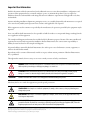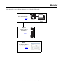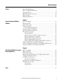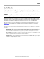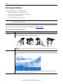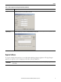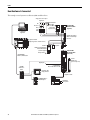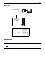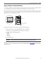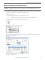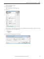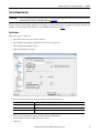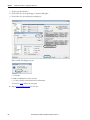
1
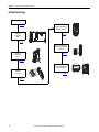
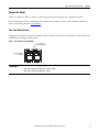
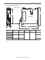
Quick Start Logix5000 Control Systems: Connect Kinetix 5500 Drives over an EtherNet/IP Network Important User Information Read this document and the documents listed in the additional resources section about installation, configuration, and operation of this equipment before you install, configure, operate, or maintain this product. Users are required to familiarize themselves with installation and wiring instructions in addition to requirements of all applicable codes, laws, and standards. Activities including installation, adjustments, putting into service, use, assembly, disassembly, and maintenance are required to be carried out by suitably trained personnel in accordance with applicable code of practice. If this equipment is used in a manner not specified by the manufacturer, the protection provided by the equipment may be impaired. In no event will Rockwell Automation, Inc. be responsible or liable for indirect or consequential damages resulting from the use or application of this equipment. The examples and diagrams in this manual are included solely for illustrative purposes. Because of the many variables and requirements associated with any particular installation, Rockwell Automation, Inc. cannot assume responsibility or liability for actual use based on the examples and diagrams. No patent liability is assumed by Rockwell Automation, Inc. with respect to use of information, circuits, equipment, or software described in this manual. Reproduction of the contents of this manual, in whole or in part, without written permission of Rockwell Automation, Inc., is prohibited. Throughout this manual, when necessary, we use notes to make you aware of safety considerations. WARNING: Identifies information about practices or circumstances that can cause an explosion in a hazardous environment, which may lead to personal injury or death, property damage, or economic loss. ATTENTION: Identifies information about practices or circumstances that can lead to personal injury or death, property damage, or economic loss. Attentions help you identify a hazard, avoid a hazard, and recognize the consequence. IMPORTANT Identifies information that is critical for successful application and understanding of the product. Labels may also be on or inside the equipment to provide specific precautions. SHOCK HAZARD: Labels may be on or inside the equipment, for example, a drive or motor, to alert people that dangerous voltage may be present. BURN HAZARD: Labels may be on or inside the equipment, for example, a drive or motor, to alert people that surfaces may reach dangerous temperatures. ARC FLASH HAZARD: Labels may be on or inside the equipment, for example, a motor control center, to alert people to potential Arc Flash. Arc Flash will cause severe injury or death. Wear proper Personal Protective Equipment (PPE). Follow ALL Regulatory requirements for safe work practices and for Personal Protective Equipment (PPE). Allen-Bradley, Rockwell Software, Rockwell Automation, CompactLogix, ControlLogix, Integrated Architecture, Kinetix, Logix5000, PanelView, POINT I/O, RSLinx, RSLogix, Stratix 5700, Studio 5000, Studio 5000 Engineering & Design Environment, and Studio 5000 Logix Designer are trademarks of Rockwell Automation, Inc. Trademarks not belonging to Rockwell Automation are property of their respective companies. Where to Start Follow this path to connect a Kinetix 5500 Drive over an EtherNet/IP Network. Prerequiste Tasks Described in Before Using This Publication 00:00:BC:2E:69:F6 1 (Front) 2 (Rear) page 8 Logix5000 Controller Logix Designer Application Chapter 1 Prepare the Kinetix 5500 Drive Hardware page 13 Chapter 2 Add a Kinetix 5500 Drive to a Logix Designer Application page 33 Rockwell Automation Publication IASIMP-QS035B-EN-P - April 2015 3 Where to Start Notes: 4 Rockwell Automation Publication IASIMP-QS035B-EN-P - April 2015 Table of Contents Preface About This Publication. . . . . . . . . . . . . . . . . . . . . . . . . . . . . . . . . . . . . . . . . . . . . 7 Before Using This Publication . . . . . . . . . . . . . . . . . . . . . . . . . . . . . . . . . . . . . . 8 Required Software . . . . . . . . . . . . . . . . . . . . . . . . . . . . . . . . . . . . . . . . . . . . . . . . . 9 How Hardware Is Connected . . . . . . . . . . . . . . . . . . . . . . . . . . . . . . . . . . . . . 10 Where to Start . . . . . . . . . . . . . . . . . . . . . . . . . . . . . . . . . . . . . . . . . . . . . . . . . . . 11 Additional Resources . . . . . . . . . . . . . . . . . . . . . . . . . . . . . . . . . . . . . . . . . . . . . 11 Chapter 1 Prepare the Kinetix 5500 Drive Hardware Before You Begin . . . . . . . . . . . . . . . . . . . . . . . . . . . . . . . . . . . . . . . . . . . . . . . . What You Need . . . . . . . . . . . . . . . . . . . . . . . . . . . . . . . . . . . . . . . . . . . . . . . . . Follow These Steps . . . . . . . . . . . . . . . . . . . . . . . . . . . . . . . . . . . . . . . . . . . . . . . Prepare the Panel. . . . . . . . . . . . . . . . . . . . . . . . . . . . . . . . . . . . . . . . . . . . . . . . . Zero-stack Tab and Cutout . . . . . . . . . . . . . . . . . . . . . . . . . . . . . . . . . . . Mount the Kinetix 5500 Drive . . . . . . . . . . . . . . . . . . . . . . . . . . . . . . . . . . . . Ground the Kinetix 5500 Drive . . . . . . . . . . . . . . . . . . . . . . . . . . . . . . . . . . . Wire Drive Connectors. . . . . . . . . . . . . . . . . . . . . . . . . . . . . . . . . . . . . . . . . . . Wiring Guidelines. . . . . . . . . . . . . . . . . . . . . . . . . . . . . . . . . . . . . . . . . . . . Wire the 24V Control Power Input Connector . . . . . . . . . . . . . . . . . Wire the Input Power Connector. . . . . . . . . . . . . . . . . . . . . . . . . . . . . . Disable the Safe Torque-off Feature. . . . . . . . . . . . . . . . . . . . . . . . . . . . Wire the Digital Inputs Connector . . . . . . . . . . . . . . . . . . . . . . . . . . . . Wire the Motor Power, Brake, and Feedback Connectors. . . . . . . . Apply the Single Motor Cable Shield Clamp . . . . . . . . . . . . . . . . . . . . . . . Connect the Kinetix 5500 Drive to the EtherNet/IP Network . . . . . . . Assign an IP Address to the Kinetix 5500 Drive. . . . . . . . . . . . . . . . . . . . . 13 13 14 15 15 16 19 20 21 21 22 23 24 24 28 30 31 Chapter 2 Add a Kinetix 5500 Drive to a Logix Designer Application Before You Begin . . . . . . . . . . . . . . . . . . . . . . . . . . . . . . . . . . . . . . . . . . . . . . . . What You Need . . . . . . . . . . . . . . . . . . . . . . . . . . . . . . . . . . . . . . . . . . . . . . . . . Follow These Steps . . . . . . . . . . . . . . . . . . . . . . . . . . . . . . . . . . . . . . . . . . . . . . . Add the Kinetix 5500 Drive to the Logix Designer Project. . . . . . . . . . . Configure the Motion Group . . . . . . . . . . . . . . . . . . . . . . . . . . . . . . . . . . . . . Configure Axis Properties . . . . . . . . . . . . . . . . . . . . . . . . . . . . . . . . . . . . . . . . Download the Program . . . . . . . . . . . . . . . . . . . . . . . . . . . . . . . . . . . . . . . Apply Power to the Kinetix 5500 Drive . . . . . . . . . . . . . . . . . . . . . . . . . . . . Test and Tune the Axis . . . . . . . . . . . . . . . . . . . . . . . . . . . . . . . . . . . . . . . . . . . Test the Axes . . . . . . . . . . . . . . . . . . . . . . . . . . . . . . . . . . . . . . . . . . . . . . . . Tune the Axes. . . . . . . . . . . . . . . . . . . . . . . . . . . . . . . . . . . . . . . . . . . . . . . . Index . . . . . . . . . . . . . . . . . . . . . . . . . . . . . . . . . . . . . . . . . . . . . . . . . . . . . . . . . . . . . . . . . 47 Rockwell Automation Publication IASIMP-QS035B-EN-P - April 2015 33 33 34 35 39 40 42 42 43 43 45 5 Table of Contents 6 Rockwell Automation Publication IASIMP-QS035B-EN-P - April 2015 Preface About This Publication This quick start provides examples and procedures for integrating a Kinetix® 5500 drive into any Logix5000™ control system over an EtherNet/IP network. The programming examples are not complex, and offer easy solutions to verify that the devices function and communicate properly. IMPORTANT This publication describes example procedures that you can complete when using a Kinetix 5500 drive over an EtherNet/IP network. The tasks that are described are not the only tasks you can complete when using a Kinetix 5500 drive in a typical Logix5000 control system. This quick start describes how to use one device on one network in a Logix5000 control system. Typically, a Logix5000 control system, operating on an EtherNet/IP network, includes a controller, power supply, and communication modules. But, in addition, the system can also include remote I/O modules, servo and/or AC drives, and HMI terminals. Other quick starts describe how to use different devices on various networks in Logix5000 control systems. For more information, see Integrated Architecture™: Logix5000 Control Systems Quick Starts Quick Reference, publication IASIMP-QR024. The beginning of each chapter contains the following information. Read these sections carefully before you start work in each chapter: • Before You Begin - This section lists the steps that must be completed and decisions that must be made before starting that chapter. You do not have to complete the chapters in this quick start in the order in which they appear, but this section defines the minimum amount of preparation required before completing the current chapter. • What You Need - This section lists the tools that are required to complete the steps in the current chapter. The the tools that are required include, but are not limited to, hardware and software. • Follow These Steps - This section illustrates the steps in the current chapter and identifies which steps are required to complete the examples using specific networks. Rockwell Automation Publication IASIMP-QS035B-EN-P - April 2015 7 Preface Before Using This Publication Do the following before you use this quick start: • Install and configure the Logix5000 controller. • Install the Studio 5000 Logix Designer™ application. • Configure the controller network. • Create a project file for your application. IMPORTANT The example graphics that are shown are for CompactLogix™ 5370 L3 controllers. The specific steps to complete the tasks depend on the Logix5000 controller you use. For more information on how to complete these tasks with specific Logix5000 controllers, see the Integrated Architecture: Logix5000 Control Systems Quick Starts Quick Reference, publication IASIMP-QR024. Table 1 - Tasks to Complete before Using This Quick Start Task Description Prepare the Logix5000 control system hardware Assemble the control system and connect to the required communication networks. Some components, for example, the Logix5000 controller and system power supply, are required. Other components, for example, a network communication module, are optional. These graphics illustrate the assembly of one example Logix5000 controller on a paint-free grounded panel. 1 (Front) 2 (Rear) IMPORTANT: This task excludes installation of other hardware components, for example, the Kinetix 5500 drives, used over the networks included in your application. Prepare the computer Install the required software on your computer. The Studio 5000 Engineering and Design Environment™ combines engineering and design elements into a common environment. The first element in the Studio 5000® environment is the Logix Designer application. Logix Designer is the rebranding of RSLogix™ 5000 software. Logix Designer is the product to program Logix5000 controllers for discrete, process, batch, motion, safety, and drive-based solutions. The Studio 5000 environment is the foundation for the future of Rockwell Automation® engineering design tools and capabilities. It is the one place for design engineers to develop all elements of their control system. 8 Rockwell Automation Publication IASIMP-QS035B-EN-P - April 2015 Preface Table 1 - Tasks to Complete before Using This Quick Start (Continued) Task Description Configure the networks Configure the controller network used in your application. This involves assigning an IP address to the controller’s communication port or communication module used in your Logix5000 control system. Create a Logix Designer application project Create a project to be used with your Logix5000 controller. A project includes all desired control system components and necessary programming. For example, add ladder logic to test tasks associated with individual system components. Required Software To complete examples in this quick start, you need the Studio 5000 Logix Designer application. The Logix Designer application is required to create or change project files that use Kinetix 5500 drives. IMPORTANT The Kinetix 5500 servo drives, and the associated tasks described in this quick start, require the Logix Designer application, version 21.00 or later. Rockwell Automation Publication IASIMP-QS035B-EN-P - April 2015 9 Preface How Hardware Is Connected This example control system uses a Kinetix 5500 standalone drive. Single-phase or Three-phase Input Power Bonded Cabinet Ground Bus 2198-DBxx-F AC Line Filter (required for CE) Line Disconnect Device Logix Designer Application Input Fusing 2198-Hxxx-ERS Kinetix 5500 Drive (top view) Mains AC and 24V Input Wired to Standard Input Connectors Logix5000 Controller (CompactLogix 5370 controller is shown) 1606-XLxxx 24V DC Control, Digital Inputs, and Motor Brake Power (customer-supplied) 00:00:BC:2E:69:F6 1 (Front) 2 (Rear) 1585J-M8CBJM-x Ethernet (shielded) Cable Allen-Bradley Safety Device 1606-XL Powe r S u p p l y Input AC Input Power 2198-Hxxx-ERS Kinetix 5500 Drive (front view) 2097-Rx Shunt Resistor (optional component) Digital Inputs 1783-BMS Stratix 5700™ Switch 2198-KITCON-DSL Motor Feedback Connector Kit PanelView™ Plus Display Terminal Bulletin 2090 Single Motor Cable 1734-AENTR POINT I/O™ EtherNet/IP Adapter 10 Rockwell Automation Publication IASIMP-QS035B-EN-P - April 2015 Bulletin VPL Rotary Motors Preface Where to Start Prerequiste Tasks Described in Before Using This Publication 00:00:BC:2E:69:F6 1 (Front) 2 (Rear) page 8 Logix5000 Controller Logix Designer Application Chapter 1 Prepare the Kinetix 5500 Drive Hardware page 11 Chapter 2 Add a Kinetix 5500 Drive to a Logix Designer Application page 31 Additional Resources Resource Description Kinetix 5500 Servo Drives User Manual, publication 2198-UM001 Describes how to install, wire, configure, operate, and troubleshoot your Kinetix 5500 drive. EtherNet/IP Modules in Logix5000 Control Systems, publication ENET-UM001 Describes how to install, configure, and operate EtherNet/IP modules. Industrial Automation Wiring and Grounding Guidelines, publication 1770-4.1 Provides general guidelines for installing a Rockwell Automation industrial system. Product Certifications website, http://www.ab.com Provides declarations of conformity, certificates, and other certification details. You can view or download publications at http://www.rockwellautomation.com/literature/. To order paper copies of technical documentation, contact your local Allen-Bradley distributor or Rockwell Automation sales representative. Rockwell Automation Publication IASIMP-QS035B-EN-P - April 2015 11 Preface Notes: 12 Rockwell Automation Publication IASIMP-QS035B-EN-P - April 2015 Chapter 1 Prepare the Kinetix 5500 Drive Hardware In this chapter, you mount the drive to your panel, make input power, motor, Ethernet, and other connections at the drive, and configure the servo drive IP address for communication over the EtherNet/IP network. Before You Begin Complete the prerequisite tasks that are related to the Logix5000 controller and Logix Designer application that is described in the Preface. What You Need This table lists the products that you need to complete the tasks in this chapter. Quantity Cat. No. Description 1 2198-Hxxx-ERS Kinetix 5500 servo drive 1 VPL-Axxxx or VPL-Bxxxx Kinetix VP Low-inertia servo motor 1 1606-XLxxx Bulletin 1606 24V DC power supply for control circuitry, digital inputs, safety, and motor brake 1 2090-CSxM1DF-xxAAxx Bulletin 2090-CSBM1DF-xxAAxx single motor cable with SpeedTec DIN connector (brake conductors included) Bulletin 2090-CSWM1DF-xxAAxx single motor cable with SpeedTec DIN connector (without brake conductors) 1 3 1585J-M8CBJM-x RJ45 to RJ45 patchcord Ethernet cables Jumper wires for disabling the safety circuit See the Kinetix 5500 Servo Drives User Manual, publication 2198-UM001, for more information on drive installation and wiring. Rockwell Automation Publication IASIMP-QS035B-EN-P - April 2015 13 Chapter 1 Prepare the Kinetix 5500 Drive Hardware Follow These Steps Prepare the Panel page 15 Apply the Single Motor Cable Shield Clamp Mount the Kinetix 5500 Drive page 28 page 16 Connect the Kinetix 5500 Drive to the EtherNet/IP Network Ground the Kinetix 5500 Drive page 30 page 19 Assign an IP Address to the Kinetix 5500 Drive L3 ove Rem DC For Only Bus Wire Drive Connectors L2 page 31 L1 page 20 14 Rockwell Automation Publication IASIMP-QS035B-EN-P - April 2015 PRECHARGE 192.168.1.1 DC BUS: 0.3V SETUP MENU PRECHARAGE 192.168.1.1 DC BUS: 0.3V SETUP MENU Prepare the Kinetix 5500 Drive Hardware Chapter 1 Prepare the Panel Mount your 2198-Hxxx-ERS servo drive on a paint-free grounded panel along with your Logix5000 controller. For more information on how to install a panel for use with a Kinetix 5500 servo drive, refer to the Kinetix 5500 Servo Drives User Manual, publication 2198-UM001. Zero-stack Tab and Cutout Engaging the zero-stack tab and cutout from drive-to-drive is optional, but the feature makes efficient use of panel space for installations with multiple standalone drives. Figure 1 - Zero-stack Tab and Cutout Example Zero-stack Tab and Cutout Engaged 2198-Hxxx-ERS Drives (front view) IMPORTANT For the zero-stack feature to engage properly (when multiple frame size are present): • frame 3 drives must mount left of frame 1 or frame 2 drives • frame 2 drives must mount left of frame 1 drives Rockwell Automation Publication IASIMP-QS035B-EN-P - April 2015 15 Chapter 1 Prepare the Kinetix 5500 Drive Hardware Mount the Kinetix 5500 Drive 1. Verify that you have met the minimum clearance requirements that are required for mounting your 2198-Hxxx-ERS servo drive. • Additional clearance is required for cables and wires or the shared-bus connection system that is connected to the top of the drive. • Additional clearance is required if other devices are installed above and/or below the drive and have clearance requirements of their own. • Additional clearance left and right of the drive is required when mounted next to noise sensitive equipment or clean wireways. • The recommended minimum cabinet depth is 300 mm (11.81 in.). Figure 2 - Minimum Clearance Requirements 40 mm (1.57 in.) clearance above drive for airflow and installation Kinetix 5500 Servo Drive Clearance left of the drive is not required. Clearance right of the drive is not required. 40 mm (1.57 in.) clearance below drive for airflow and installation IMPORTANT 16 Mount the drive in an upright position as shown. Do not mount the drive on its side. Rockwell Automation Publication IASIMP-QS035B-EN-P - April 2015 Prepare the Kinetix 5500 Drive Hardware Chapter 1 Figure 3 - Dimensions - Kinetix 5500 Servo Drives Dimensions are in mm (in.) E B 2198-H003-ERS servo drive is shown. 3.0 (0.12) C A D Kinetix 5500 Drive Cat. No. A mm (in.) B mm (in.) C mm (in.) D mm (in.) E mm (in.) 2198-H003-ERS 50 (1.97) 170 (6.69) 200 (7.87) 226 (8.90) 215 (8.46) 55 (2.16) 225 (8.86) 265 (10.43) 85.2 (3.35) 250 (9.84) 294 (11.57) 2198-H008-ERS 2198-H015-ERS 2198-H025-ERS 2198-H040-ERS 2198-H070-ERS Rockwell Automation Publication IASIMP-QS035B-EN-P - April 2015 17 Chapter 1 Prepare the Kinetix 5500 Drive Hardware 2. Drill the hole pattern for your frame 1, frame 2, or frame 3 standalone drive. Frame 1 Standalone Drive 4.51 (0.2) 8x ØM4 (#8-32) 272.0 (10.7) 243.84 (9.6) 193.68 (7.6) Frame 3 Standalone Drive Frame 2 Standalone Drive 34.00 (1.3) 5.00 (0.2) 0 0 0 Dimensions are in mm (in.) 0 0 0 52.50 (2.1) These hole patterns are only for standalone drive installations. If you have multiple drives to mount and would like to use the zero-stack mounting feature, refer to the Kinetix 5500 Servo Drives User Manual, publication 2198-UM001, for additional hole patterns and mounting information. 3. Attach your drive to the panel. The recommended mounting hardware is M4 (#8-32) steel bolts. Observe bonding techniques as described in the user manual. 4. Tighten all mounting fasteners. Apply 2.0 N•m (17.7 lb•in) maximum torque to each fastener. 18 Rockwell Automation Publication IASIMP-QS035B-EN-P - April 2015 Prepare the Kinetix 5500 Drive Hardware Chapter 1 Ground the Kinetix 5500 Drive 1. Ground Kinetix 5500 drives to a bonded cabinet ground bus with a braided ground strap or 4.0 mm2 (12 AWG) copper wire. Kinetix 5500 Servo Drive (standalone) Multiple standalone drives using zero-stack feature. Item Description 1 Ground screw (green) 2.0 N•m (17.5 lb-in), max 2 Braided ground strap (customer supplied) 3 Ground grid or power distribution ground 4 Bonded cabinet ground bus (customer supplied) 1 2 3 Braided Ground Straps 25.4 mm (1.0 in.) by 6.35 mm (0.25 in.). Keep lengths as short as possible. 4 2. Grounded power distribution is recommended; however, for ungrounded or corner-ground power, remove the two grounding screws. The two grounding screws are behind the sliding door on the drive side panel. Grounding Screws Access Door Kinetix 5500 Drive (side view) Lift door to meet arrow at left. Grounding screws that are installed for grounded power configuration (screws installed is the default setting). Remove screws for ungrounded power distribution. See the Kinetix 5500 Servo Drives User Manual, publication 2198-UM001, for additional information on grounding the drive and ungrounded power distribution. Rockwell Automation Publication IASIMP-QS035B-EN-P - April 2015 19 Chapter 1 Prepare the Kinetix 5500 Drive Hardware Wire Drive Connectors Kinetix 5500 servo drives are capable of 200V-class (single/three-phase) and 400V-class (three-phase) operation. This wiring diagram is for 200/400V-class, three-phase operation. For additional interconnect wiring diagrams, refer to the Kinetix 5500 Servo Drives User Manual, publication 2198-UM001. Figure 4 - Interconnect Wiring Diagram 2198-Hxxx-ERS Kinetix 5500 Drives Bonded Cabinet Ground Bus * PE Ground Note 4 Chassis Note 2 2 Customer Supplied +24V DC Power Supply * 1 Control Power (CP) Connector 24V_COM +24V Note 3 Cable Shield Clamp U 4 2198-DBxx-F Three-phase AC Line Filter Note 1 195…264V AC rms or 324…528V AC rms Three-phase Input 3 2 1 L3 Motor Power (MP) Connector Mains AC Input (IPD) Connector V W 4 Three-phase Motor Power Connections 3 2 1 L2 L1 Input Fusing * DC+ DC- DC+ SH Motor Brake (BC) Connector DC Bus (DC) Connector Note 5 Shunt (RC) Connector MBRK MBRK + Motor Feedback (MF) Connector D+ Digital Input (IOD) Connector COM Internal Shunt Note 6 D- IN1 IN2 * Indicates User Supplied Component Ground Screws Note 7 SHLD 2 MBRK - 1 MBRK + 1 DATA +/EPWR+ 2 DATA -/EPWR- Motor Brake Connections Motor Feedback Connections 1 2 3 Registration and Home Input Connections 4 Table 2 - Interconnect Diagram Notes Note Information 1 AC (EMC) line filter is required for EMC compliance. Place line filter as close to the drive as possible and do not route very dirty wires in wireway. If routing in wireway is unavoidable, use shielded cable with shields grounded to the drive chassis and filter case. For AC line filter specifications, refer to Kinetix Servo Drives Specifications Technical Data, publication GMC-TD003. 2 Terminal block is required to make connections. 3 Cable shield clamp must be used to meet CE requirements. 4 PE ground connection bonded to the panel must be used to meet CE requirements. 5 DC connector covered with protective knockout is default configuration. Wiring the DC connector does not apply to standalone drives. 6 Internal shunt wired to the RC connector is default configuration. Remove internal shunt wires to attach external shunt wires. 7 Default configuration for ground screws is for grounded power at user site. For ungrounded or corner-grounded power, remove the screws. Refer to Ground the Kinetix 5500 Drive on page 19 for more information. 20 Rockwell Automation Publication IASIMP-QS035B-EN-P - April 2015 Prepare the Kinetix 5500 Drive Hardware Chapter 1 Wiring Guidelines Follow these steps when wiring the connectors for your Kinetix 5500 drive. 1. Prepare the wires for attachment to each connector plug by removing insulation equal to the recommended strip length. IMPORTANT When you remove insulation from wires and tighten screws to secure the wires, refer to the tables provided for strip lengths and torque values. Use caution not to nick, cut, or otherwise damage strands as you remove the insulation. 2. Route the cable/wires to your Kinetix 5500 drive. See the interconnect wiring diagram on page 20 for connector pinouts. 3. Insert wires into connector plugs. 4. Tighten the connector screws. 5. Gently pull on each wire to make sure that it does not come out of its terminal; reinsert and tighten any loose wires. 6. Insert the connector plug into the drive connector. Wire the 24V Control Power Input Connector The 24V power (CP) connector requires 24V DC input for the control circuitry. Kinetix 5500 Drive Top View 2 24V (CP) Connector Plug ove Rem r DC Fo Only Bus 24V + 24V 1 Table 3 - 24V Power (CP) Connector Specifications Drive Cat. No. CP Pin Signal Recommended Wire Size mm2 (AWG) Strip Length mm (in.) Torque Value N•m (lb•in) 2198-Hxxxx-ERS CP-1 24V+ 7.0 (0.28) CP-2 24V- 2.5…0.5 (14…20) 0.22…0.25 (1.9…2.2) Rockwell Automation Publication IASIMP-QS035B-EN-P - April 2015 21 Chapter 1 Prepare the Kinetix 5500 Drive Hardware Wire the Input Power Connector The input power (IPD) connector requires 195…528V AC (single-phase or three-phase) for mains input power. ATTENTION: Make sure that the input power connections are correct when wiring the IPD connector plug and that the plug is fully engaged in the drive connector. Incorrect wiring/polarity or loose wiring can cause explosion or damage to equipment. Kinetix 5500 Drive Top View ove Rem r DC Fo Only Bus L3 Input Power (IPD) Connector Plug L2 L1 Table 4 - Input Power (IPD) Connector Specifications Kinetix 5500 Drive Cat. No. 2198-H003-ERS 2198-H008-ERS 2198-H015-ERS 2198-H025-ERS 2198-H040-ERS 2198-H070-ERS 22 Pin L3 L2 L1 Signal L3 L2 L1 Recommended Wire Size mm2 (AWG) Strip Length mm (in.) Torque Value N•m (lb•in) 1.5…4 (16…12) 8.0 (0.31) 0.5…0.6 (4.4…5.3) 1.5…6 (16…10) Rockwell Automation Publication IASIMP-QS035B-EN-P - April 2015 Prepare the Kinetix 5500 Drive Hardware Chapter 1 Disable the Safe Torque-off Feature The safe torque-off circuit is designed to safely turn off all of the output-power transistors. Each Kinetix 5500 drive ships with one 10-pin wiring plug for wiring to safety devices. The drive does not operate without a safety circuit or safety bypass wiring. For applications that do not require the safe torque-off feature, you must install jumper wires to bypass the safe torque-off circuitry. The application used in this quick start does not include safety devices, so you must disable the safe torque off feature. The safe torque-off (STO) connector uses spring tension to secure the wire. Depress the tab, along side each pin, to insert or release the wire. Two rows of pins are provided for drive-to-drive connections. 1 Safe Torque-off (STO) Connector Plug IMPORTANT 2 SB+SB S1 SC S2 3 4 ove Rem r DC Fo Only Bus Kinetix 5500 Drive Top View 5 Stranded wires must terminate with ferrules to prevent short circuits, per table D7 of EN 13849. Table 5 - Safe Torque-off (STO) Terminal Plug Wiring Safe Torque-off (STO) Connector Pin Signal STO-1 STO-2 STO-3 STO-4 STO-5 SB+ SB- S1 SC S2 Recommended Wire Size mm2 (AWG) Strip Length mm (in.) Torque Value N•m (lb•in) 1.5…0.2 (16…24) 10 (0.25) N/A To bypass the safety function, wire these signals as shown. With the jumper wires installed, the safe-off feature is not used. Safe Torque-off (STO) Connectors Pin 1 SB+ SBS1 SC S2 For more information on the safe torque-off feature, see Kinetix 5500 Servo Drives User Manual, publication 2198UM001. Rockwell Automation Publication IASIMP-QS035B-EN-P - April 2015 23 Chapter 1 Prepare the Kinetix 5500 Drive Hardware Wire the Digital Inputs Connector The digital inputs (IOD) connector uses spring tension to hold wires in place. Kinetix 5500 Servo Drive (front view) 1 IN1 COM IN2 SHLD Digital Inputs (IOD) Connector Plug Table 6 - Digital Inputs (IOD) Connector Specifications Drive Cat. No. DC Pin Signal Recommended Wire Size mm2 (AWG) Strip Length mm (in.) Torque Value N•m (lb•in) 2198-Hxxxx-ERS IOD-1 IOD-2 IOD-3 IOD-4 IN1 (1) COM IN2 SHLD 1.5…0.2 (16…24) 10.0 (0.39) N/A (1) This signal has dual-functionality. You can use IN1 (IOD-1) as registration or Home input. Wire the Motor Power, Brake, and Feedback Connectors The Kinetix 5500 drives use one cable that includes conductors for motor power, brake, and encoder feedback. Bulletin 2090 cables are available with and without the motor brake conductors. See the Kinetix Motion Accessories Specifications Technical Data, publication GMC-TD004, for cable specifications. Table 7 - Single Cable Catalog Numbers Motor Connector Type Motor Cat. No. Motor Cable Cat. No. (with brake wires) Motor Cable Cat. No. (without brake wires) Kinetix VP (Bulletin VPL) Circular DIN (SpeedTec) VPL-A/Bxxxxx 2090-CSBM1DF-xxAAxx (standard) cable 2090-CSWM1DF-xxAAxx (standard) cable 24 Rockwell Automation Publication IASIMP-QS035B-EN-P - April 2015 Prepare the Kinetix 5500 Drive Hardware Chapter 1 Motor Power Connections Kinetix 5500 Servo Drive (front view) U V Motor Power (MP) Connector Plug W Motor Cable Shield Clamp ATTENTION: Make sure that the motor power connections are correct when wiring the MP connector plug and that the plug is fully engaged in the module connector. Incorrect wiring/polarity or loose wiring can cause an explosion or damage to equipment. Table 8 - Motor Power (MP) Connector Specifications Drive Cat. No. 2198-H003-ERS 2198-H008-ERS 2198-H015-ERS 2198-H025-ERS 2198-H040-ERS 2198-H070-ERS Pin Signal/Wire Color U V W U Brown V Black W Blue Green/Yellow Recommended Wire Size mm2 (AWG) Strip Length mm (in.) Torque Value N•m (lb•in) Motor power cable depends on motor/ drive combination. 0.75…2.5 (18…14) max 8.0 (0.31) 0.5…0.6 (4.4…5.3) 2.5…6 (14…10) max Rockwell Automation Publication IASIMP-QS035B-EN-P - April 2015 25 Chapter 1 Prepare the Kinetix 5500 Drive Hardware Motor Brake Connections Kinetix 5500 Servo Drive (front view) 2 1 MBRKMBRK+ Motor Brake (BC) Connector Plug Motor Cable Shield Clamp Table 9 - Motor Brake (BC) Connector Specifications Drive Cat. No. Pin Signal/ Wire Color Recommended Wire Size (AWG) Strip Length mm (in.) Torque Value N•m (lb•in) 2198-Hxxx-ERS BC-1 MBRK+/Black N/A (1) 8.0 (0.31) BC-2 MBRK-/White 0.22…0.25 (1.9…2.2) (1) Motor brake wires are part of the 2090-CSBM1DF-xxAAxx motor cable. 26 Rockwell Automation Publication IASIMP-QS035B-EN-P - April 2015 Prepare the Kinetix 5500 Drive Hardware Chapter 1 Motor Feedback Connections Feedback connections are made by using the 2090-KITCON-DSL feedback connector kit, which is included with your Kinetix 5500 drive. Kinetix 5500 Servo Drive (front view) See the Kinetix 5500 Feedback Connector Kit Installation Instructions, publication 2198-IN002, for connector kit specifications. Mounting Screws (2) Motor Feedback Connector Kit 2198-KITCON-DSL Feedback Connector Kit Cover Clamp Screws (2) Exposed Shield Motor Cable Shield Clamp Connector Housing Feedback Cable (EPWR+, EPWR-) 2090-CSxM1DF-18AAxx Motor Cable Internal Grounding Plate Table 10 - Motor Feedback (MF) Connector Specifications Drive Cat. No. Pin Signal/ Wire Color Wire Size AWG Strip Length mm (in.) Torque Value N•m (lb•in) 2198-Hxxx-ERS MF-1 D+/Blue 22 8.0 (0.31) 0.4 (3.5) MF-2 D-/White IMPORTANT The feedback bundle in 2090-CSxM1DF-18AAxx motor cables (typically used with frame 1 drives) route around the shield clamp (as shown in the graphic). The feedback bundle in 14 AWG and 10 AWG cables (typically used with frame 2 and 3 drives) route with the power and brake wires inside the cable shield. Rockwell Automation Publication IASIMP-QS035B-EN-P - April 2015 27 Chapter 1 Prepare the Kinetix 5500 Drive Hardware Apply the Single Motor Cable Shield Clamp Factory-supplied 2090-Series single motor cables are shielded, and the braided cable shield must end at the drive during installation. A small portion of the cable jacket has been removed to expose the shield braid. The exposed area must be clamped (with the clamp provided) at the bottom front of the drive. SHOCK HAZARD: To avoid hazard of electrical shock, make sure that shielded power cables are grounded according to recommendations. This procedure assumes that you have completed wiring your motor power, brake, and feedback connectors and are ready to apply the cable shield clamp. Follow these steps to apply the motor cable shield clamp. 1. Loosen the clamp screws and remove at least one of the screws. Figure 5 - 18 AWG Cable Installation Kinetix 5500 Servo Drives (frame 1) Front View Motor Power (MP) Connector 2198-KITCON-DSL Motor Feedback Connector Kit Motor Cable Shield Clamp Motor Brake (BC) Connector Exposed shield braid under clamp. Cable clamp screws tightened. Feedback cable routed around the shield clamp. TIP 28 2090-CSBM1DF-18AAxx Motor Cable When the drive/motor combination calls for 18 AWG cable, the feedback cable routes around the motor cable shield clamp. Rockwell Automation Publication IASIMP-QS035B-EN-P - April 2015 Prepare the Kinetix 5500 Drive Hardware Chapter 1 Figure 6 - 14 AWG and 10 AWG Cable Installation Kinetix 5500 Servo Drives (frame 2 or 3) Front View 2198-KITCON-DSL Motor Feedback Connector Kit Motor Power (MP) Connector Motor Brake (BC) Connector Clamp features apply to all frame sizes. Retention Screw (loosen, do not remove) Feedback cable routed within the shield braid. Motor Cable Shield Clamp Exposed shield braid under clamp. Torque clamp screws to 2.0 N•m (17.5 lb-in), max Cable clamp screws tightened. 2090-CSBM1DF-14AAxx or 2090-CSBM1DF-10AAxx Motor Cables TIP When the drive/motor combination calls for 14 AWG or 10 AWG cable, the feedback cable routes along with the power and brake wiring. 2. Position the exposed portion of the cable braid directly in line with the clamp. 3. Tighten the clamp screws to a torque value of 2.0 N•m (17.7 lb•in) maximum. 4. Repeat step 1 through step 3 for each drive in multi-axis configurations. Rockwell Automation Publication IASIMP-QS035B-EN-P - April 2015 29 Chapter 1 Prepare the Kinetix 5500 Drive Hardware Connect the Kinetix 5500 Drive to the EtherNet/IP Network Ethernet connections are made at the PORT 1 and PORT 2 connectors. The Kinetix 5500 drives include two RJ45 connectors to support linear and ring topologies when multiple standalone drives are present. Kinetix 5500 Servo Drive (single, standalone) Kinetix 5500 Servo Drives (multiple, standalone) 1585J-M8CBJM-OM3 0.3 m (1.0 ft) Ethernet cable for drive-to-drive connections. PORT 1 and PORT 2 Ethernet Connectors 30 Rockwell Automation Publication IASIMP-QS035B-EN-P - April 2015 Prepare the Kinetix 5500 Drive Hardware Chapter 1 Assign an IP Address to the Kinetix 5500 Drive You can assign an IP address to the Kinetix 5500 drive manually via the drive keypad, or dynamically via a DHCP-enabled server. This publication describes tasks to manually assign an IP Address for use in a private network. The Kinetix 5500 drive has two status indicators and an LCD status display. The indicators and display are used to monitor the system status, set network parameters, and troubleshoot faults. Four navigation buttons are located directly below the display and are used to select items from a soft menu. PRECHARGE 192.168.1.1 DC BUS: 0.3V SETUP MENU Status Indicators PRECHARAGE 192.168.1.1 DC BUS: 0.3V SETUP MENU Soft Menu Navigation Buttons You program network parameters by using the LCD display and navigation buttons. 1. From the LCD display, select SETUP>NETWORK and choose STATIC IP. The default network setting is STATIC IP with an IP address of 192.168.1.1. 2. Press to configure the following parameters: • IP address • Gateway • Subnet mask 3. Cycle 24V control power. IMPORTANT Changes to the IP address, Gateway, and Subnet mask take effect only after cycling 24V control power. Settings are stored in nonvolatile memory. You can also change the IP address through the Module Configuration dialog box in RSLinx® software. See the Kinetix 5500 Servo Drives User Manual, publication 2198-UM001, for help setting the network parameters. Rockwell Automation Publication IASIMP-QS035B-EN-P - April 2015 31 Chapter 1 Prepare the Kinetix 5500 Drive Hardware Notes: 32 Rockwell Automation Publication IASIMP-QS035B-EN-P - April 2015 Chapter 2 Add a Kinetix 5500 Drive to a Logix Designer Application In this chapter, you add the Kinetix 5500 servo drive to your Logix Designer application project, download the project to the Logix5000 controller, and verify communication between drive and motor by applying power and testing an axis. Before You Begin Complete wiring the connector plugs, connecting the Ethernet cables, and configuring the IP address for your Kinetix 5500 drive (refer to Chapter 1). What You Need • Logix Designer application, version 21.00 or later • The Kinetix 5500 Servo Drives User Manual, publication 2198-UM001 Rockwell Automation Publication IASIMP-QS035B-EN-P - April 2015 33 Chapter 1 Add a Kinetix 5500 Drive to a Logix Designer Application Follow These Steps Apply Power to the Kinetix 5500 Drive L3 ove Rem DC For Only Bus Add the Kinetix 5500 Drive to the Logix Designer Project L2 L1 page 35 Configure the Motion Group page 39 page 42 Test and Tune the Axis page 43 Configure Axis Properties page 40 34 Rockwell Automation Publication IASIMP-QS035B-EN-P - April 2015 Add a Kinetix 5500 Drive to a Logix Designer Application Chapter 1 Add the Kinetix 5500 Drive to the Logix Designer Project IMPORTANT To configure Kinetix 5500 drives (catalog numbers 2198-Hxxx-ERS), you must use Logix Designer Application, version 21.00 or later. 1. Verify that power is not applied at the mains input power (IPD) connector or the 24V input power (CP) connector. 2. Verify that the following is true for your Logix Designer application project: • The project is offline • The controller is configured such that Time Synchronization is enabled TIP The Enable Time Synchronization feature is on the Date/Time tab of the Controller Properties dialog box. 3. Verify the Logix5000 controller mode switch is in the PROG mode position. RUN REM PROG 4. Right-click your network port and choose New Module. The Select Module Type dialog box opens. 5. Using the filters, check Motion and Allen-Bradley, and select your 2198-Hxxx-ERS servo drive as appropriate for your actual hardware configuration. 6. Click Create. The New Module dialog box opens. Rockwell Automation Publication IASIMP-QS035B-EN-P - April 2015 35 Chapter 1 Add a Kinetix 5500 Drive to a Logix Designer Application 7. Configure the new drive. a. On the New Module dialog box, type the drive Name. b. Select an Ethernet Address option. In this example, the Private Network address is selected. c. Enter the address of your EtherNet/IP module. In this example, the last octet of the address is 1. The IP address must match the IP address that you configured on page 29. d. Click OK to close the New Module dialog box. Your 2198-Hxxx-ERS servo drive appears in the Controller Organizer under the Ethernet controller in the I/O Configuration folder. 8. On the Select Module Type dialog box, click Close. 9. Right-click the 2198-Hxxx-ERS servo drive that you created, and choose Properties. The Module Properties dialog box opens. 10. Click the Associated Axes tab. 11. On the Associated Axes tab, click New Axis. 36 Rockwell Automation Publication IASIMP-QS035B-EN-P - April 2015 Add a Kinetix 5500 Drive to a Logix Designer Application Chapter 1 The New Tag dialog box opens. 12. Type the axis Name. AXIS_CIP_DRIVE is the default Data Type. 13. Click Create. The axis (Axis_1 in this example) appears in the Controller Organizer under Motion Groups>Ungrouped Axes and is assigned as Axis 1 on the Associated Axes tab. 14. On the Module Properties dialog box, click Apply. Rockwell Automation Publication IASIMP-QS035B-EN-P - April 2015 37 Chapter 1 Add a Kinetix 5500 Drive to a Logix Designer Application 15. Click the Power tab. 16. From the pull-down menus, choose the power options appropriate for your actual hardware configuration. Attribute Menu Description Voltage • 400-480 VAC • 200-240 VAC AC input voltage class. AC Input Phasing • Three Phase • Single Phase AC input phase. Kinetix 5500 drives with singlephase operation are limited to 2198-H003-ERS, 2198-H008-ERS, and 2198-H015-ERS. Bus Configuration (1) Standalone Applies to single-axis drives and drives with Shared AC input configurations. Shared AC/DC Applies to converter drives with Shared AC/DC and Shared AC/DC Hybrid input configurations. Shared DC Applies to inverter drives with Shared DC input (common-bus) configurations. Standalone Applies to standalone bus configurations. • Group1 • Group2 • Group3… Applies to any bus sharing configuration. Disabled Disables the internal shunt resistor and external shunt option. Shunt Regulator Enables the internal and external shunt options. Internal Enables the internal shunt (external shunt option is disabled). External Enables the external shunt (internal shunt option is disabled). • None • 2097-R6 • 2097-R7 Selects external shunt option. Only the shunt model that is intended for the drive model is shown. Bus Sharing Group (1) Shunt Regulator Action Shunt Regulator Resistor Type External Shunt (2) (1) See the Kinetix Servo Drives User Manual, publication 2198-UM001, for more information on bus configuration and bus sharing. For this quick start, configure these fields as Standalone. (2) See the Kinetix Servo Drives Specifications Technical Data, publication GMC-TD003, for more information on the Bulletin 2097 external shunt resistors. 17. Click OK. 18. Repeat step 1 through step 17 for each 2198-Hxxx-ERS servo drive. 38 Rockwell Automation Publication IASIMP-QS035B-EN-P - April 2015 Add a Kinetix 5500 Drive to a Logix Designer Application Chapter 1 Configure the Motion Group Follow these steps to configure the motion group. 1. In the Controller Organizer, right-click Motion Groups and choose New Motion Group. The New Tag dialog box opens. 2. Type the new motion group Name. 3. Click Create. Your new motion group appears in the Controller Organizer under the Motion Groups folder. 4. Right-click the new motion group and choose Properties. The Motion Group Properties dialog box opens. 5. Click the Axis Assignment tab and move your axes (created earlier) from Unassigned to Assigned. 6. Click OK. Your axis moves to the new motion group. Rockwell Automation Publication IASIMP-QS035B-EN-P - April 2015 39 Chapter 1 Add a Kinetix 5500 Drive to a Logix Designer Application Configure Axis Properties Follow these steps to configure the servo motor axis properties. 1. In the Controller Organizer, right-click an axis and choose Properties. 2. Select the General category. The General and Associated Module dialog box opens. 3. From the General pull-down menus, change configuration settings as needed for your application. 4. From the Associated Module>Module pull-down menu, choose your Kinetix 5500 drive. The drive catalog number populates the Module Type and Power Structure fields. 5. Click Apply. 6. Select the Motor category. 40 Rockwell Automation Publication IASIMP-QS035B-EN-P - April 2015 Add a Kinetix 5500 Drive to a Logix Designer Application Chapter 1 The Motor Device Specification dialog box opens. 7. From the Data Source pull-down menu, choose Catalog Number. 8. Click Change Catalog. The Change Catalog Number dialog box opens. 9. Select the motor catalog number appropriate for your application. To verify the motor catalog number, refer to the motor name plate. 10. On the Change Catalog Number dialog box, click OK. 11. On the Motor Device Specification dialog box, click Apply. Motor data specific to your motor appears in the Nameplate / Datasheet - Phase to Phase parameters field. 12. On the Motor Device Specification dialog box, click OK. 13. Repeat step 1 through step 12 for each servo motor axis. Rockwell Automation Publication IASIMP-QS035B-EN-P - April 2015 41 Chapter 1 Add a Kinetix 5500 Drive to a Logix Designer Application Download the Program 1. Complete the Logix Designer application project and save your file. 2. Download your program to the Logix5000 processor. 3. Verify that the controller is in Run mode. Apply Power to the Kinetix 5500 Drive This procedure assumes that you have wired and configured your Kinetix 5500 system and Logix5000 controller. SHOCK HAZARD: To avoid hazard of electrical shock, perform all mounting and wiring of the Bulletin 2198 servo drives before you apply power. Once power is applied, connector terminals can have voltage present even when not in use. Follow these steps to apply power to the Kinetix 5500 system. 1. Disconnect the load to the motor. ATTENTION: To avoid personal injury or damage to equipment, disconnect the load to the motor. Make sure that each motor is free of all linkages when you initially apply power to the system. 2. Apply 24V DC control power. The LCD display begins the start-up sequence. If the start-up sequence does not begin, check the 24V control power connections. 3. When the start-up sequence completes, verify that the two status indicators are steady green and the axis state is PRECHARGE. 4. Apply mains input power and monitor the DC BUS voltage on the LCD display. If the DC BUS does not reach the expected voltage level, check the three-phase input power connections. Also, it can take as many as 1.8 seconds after input power is applied before the drive can accept motion commands. 5. Verify that the axis state changes to STOPPED. For more information on the Kinetix 5500 start-up sequence, troubleshooting status indicators, and troubleshooting fault codes, refer to the Kinetix 5500 Servo Drives User Manual, publication 2198-UM001. 42 Rockwell Automation Publication IASIMP-QS035B-EN-P - April 2015 Add a Kinetix 5500 Drive to a Logix Designer Application Chapter 1 Test and Tune the Axis IMPORTANT Before proceeding with testing and tuning your axes, verify that the MOD and NET status indicators are operating as described in the Kinetix 5500 Servo Drives User Manual, publication 2198-UM001. For help using the Logix Designer application as it applies to testing and tuning your axes with ControlLogix® EtherNet/IP modules or CompactLogix 5370 controllers, refer to Additional Resources on page 9. Test the Axes Follow these steps to test the axes. 1. Verify that the load was removed from each axis. 2. In your Motion Group folder, right-click an axis and choose Properties. The Axis Properties dialog box opens. 3. Click the Hookup Tests category. 4. In the Test Distance field, type 2.0 as the number of revolutions for the test. Test Description Marker Verifies marker detection capability as you rotate the motor shaft. Motor Feedback Verifies that feedback connections are wired correctly as you rotate the motor shaft. Motor and Feedback Verifies that motor power and feedback connections are wired correctly as you command the motor to rotate. 5. Click the desired tab (Marker/Motor Feedback/Motor and Feedback). In this example, the Motor and Feedback test is chosen. 6. Click Start. Rockwell Automation Publication IASIMP-QS035B-EN-P - April 2015 43 Chapter 1 Add a Kinetix 5500 Drive to a Logix Designer Application The Logix Designer - Motor and Feedback Test dialog box opens. The Test State is Executing. TESTING appears on the drive LCD display. TESTING 192.168.1.1 DC BUS: 218.3V SETUP MENU Drive LCD Display When the test completes successfully, the Test State changes from Executing to Passed. 7. On the Motor and Feedback Test dialog box, click OK. A dialog box opens asking if the direction was correct. 8. Click Yes. 9. On the Axis Properties dialog box, click Accept Test Results. If the test fails, this dialog box opens. a. b. c. d. 44 Click OK. Verify the DC bus voltage. Verify unit values entered in the Scaling category. Return to step 5 and run the test again. Rockwell Automation Publication IASIMP-QS035B-EN-P - April 2015 Add a Kinetix 5500 Drive to a Logix Designer Application Chapter 1 Tune the Axes Follow these steps to tune the axes. 1. Verify that the load is still removed from the axis being tuned. ATTENTION: To reduce the possibility of unpredictable motor response, tune your motor with the load removed first, then reattach the load and perform the tuning procedure again to provide an accurate operational response. 2. Click the Autotune category. 3. Type values for Travel Limit and Speed. In this example, Travel Limit = 5 and Speed = 10. The actual values of programmed units depend on your application. 4. From the Direction pull-down menu, choose a setting appropriate for your application. Forward Uni-directional is default. 5. Edit other fields as appropriate for your application. 6. Click Start. The Logix Designer - Autotune dialog box opens. When the test completes, the Test State changes from Executing to Success. Tuned values populate the Loop and Load parameter tables. Actual bandwidth values (Hz) depend on your application and can require adjustment once motor and load are connected. Rockwell Automation Publication IASIMP-QS035B-EN-P - April 2015 45 Chapter 1 Add a Kinetix 5500 Drive to a Logix Designer Application 7. Click Accept Tuned Values. 8. Click OK to close the Logix Designer - Autotune dialog box. 9. Click OK to close the Axis Properties dialog box. If the test fails, this dialog box opens. a. b. c. d. Click OK. Make an adjustment to motor velocity. See the controller user manual for more information. Return to step 6 and run the test again. 10. Repeat Test and Tune the Axis for each axis. 46 Rockwell Automation Publication IASIMP-QS035B-EN-P - April 2015 Index Numerics 24V input power connector wiring 21 A applying power 42 associated axes tab 36 B BC connector wiring 26 bus regulator 38 C cables catalog numbers 24 Ethernet 13 shield clamp 28 SpeedTec DIN 13 catalog numbers motor cables 24 clamp 28 clearance requirements 16 configuring hookup test 43 module properties 36, 37, 38 motion group 39 motor test 43 tune 45 servo motor axis general category 40 motor category 41 connecting motor shield clamp 28 connections drive to EtherNet/IP network 30 hardware 10 control power wiring 21 CP connector wiring 21 D digital inputs wiring 24 dimensions 17 download program 42 drive preparation mount 16-18 Rockwell Automation Publication IASIMP-QS035B-EN-P - April 2015 E EMC motor ground termination 28 Ethernet cables 13 EtherNet/IP network connect drive 30 G general category 40 tab 36 ground screws 19 H hardware example control system 10 ground drive 19 mount drive 16-18 preparation 13-31 hole patterns 18 hookup test 43 I input power wiring 24V control 21 mains 22 interconnect diagram 20 IOD connector wiring 24 IP address assign to drive 31 IPD connector wiring 22 L LCD display 31 Logix Designer application 33 add drive to project 35-38 software 9 Logix5000 controllers prerequisite tasks 8-9 M mains input power connector wiring 22 MF connector wiring 27 mode switch 35 47 module properties associated axes tab 36 general tab 36 new tag 37 power tab 38 motion group 39 motors brake connector wiring 26 Bulletin VPL 13 cable catalog numbers 24 category 41 feedback connector wiring 27 ground termination 28 power connector wiring 25 shield clamp wiring 28 testing 43 tuning 43 mounting your drive clearance requirements 16 dimensions 17 hole patterns 18 zero-stack tab and cutout 15 MP connector wiring 25 N new tag data type 37 P panel preparation 15 power supply 24V DC 13 power tab bus regulator 38 power structure 38 power up 42 prerequisite tasks 8-9 R requirements hardware preparation 13-31 Logix Designer application 9 prerequisite tasks 8-9 S safe torque-off wiring 23 shield clamp 28 software Logix Designer application 9, 35-38 SpeedTec DIN cables 13 status indicators 31 48 Rockwell Automation Publication IASIMP-QS035B-EN-P - April 2015 STO connector wiring 23 T testing axes hookup test 43 tuning axes autotune category 45 W where to start 11 wiring BC connector 26 CP connector 21 guidelines 21 interconnect diagram 20 IOD connector 24 IPD connector 22 MF connector 27 motor cable shield clamp 28 MP connector 25 STO connector 23 Z zero-stack tab and cutout 15 Rockwell Automation Support Rockwell Automation provides technical information on the Web to assist you in using its products. At http://www.rockwellautomation.com/support you can find technical and application notes, sample code, and links to software service packs. You can also visit our Support Center at https://rockwellautomation.custhelp.com/ for software updates, support chats and forums, technical information, FAQs, and to sign up for product notification updates. In addition, we offer multiple support programs for installation, configuration, and troubleshooting. For more information, contact your local distributor or Rockwell Automation representative, or visit http://www.rockwellautomation.com/services/online-phone. Installation Assistance If you experience a problem within the first 24 hours of installation, review the information that is contained in this manual. You can contact Customer Support for initial help in getting your product up and running. United States or Canada 1.440.646.3434 Outside United States or Canada Use the Worldwide Locator at http://www.rockwellautomation.com/rockwellautomation/support/overview.page, or contact your local Rockwell Automation representative. New Product Satisfaction Return Rockwell Automation tests all of its products to help ensure that they are fully operational when shipped from the manufacturing facility. However, if your product is not functioning and needs to be returned, follow these procedures. United States Contact your distributor. You must provide a Customer Support case number (call the phone number above to obtain one) to your distributor to complete the return process. Outside United States Please contact your local Rockwell Automation representative for the return procedure. Documentation Feedback Your comments will help us serve your documentation needs better. If you have any suggestions on how to improve this document, complete this form, publication RA-DU002, available at http://www.rockwellautomation.com/literature/. Rockwell Automation maintains current product environmental information on its website at http://www.rockwellautomation.com/rockwellautomation/about-us/sustainability-ethics/product-environmental-compliance.page. Rockwell Otomasyon Ticaret A.Ş., Kar Plaza İş Merkezi E Blok Kat:6 34752 İçerenköy, İstanbul, Tel: +90 (216) 5698400 Publication IASIMP-QS035B-EN-P - April 2015 Supersedes Publication IASIMP-QS035A-EN-P - December 2012 Copyright © 2015 Rockwell Automation, Inc. All rights reserved. Printed in the U.S.A.