1
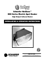
Schaefer HotZone™
HZS Series Electric Spot Heater
High Output Infrared Heater
INSTALLATION & OPERATION INSTRUCTIONS
®
41344
800-779-3267
[email protected] • www.schaeferfan.com
©2008 Schaefer Ventilation Equipment
Contents
1.0
ABOUT YOUR HotZone™ HEATER . . . . . . . . . . . . . . . . . . . . . . . . . . . . . . . . . . . . . . . . . . . . . . . .1
2.0
IMPORTANT INSTRUCTIONS . . . . . . . . . . . . . . . . . . . . . . . . . . . . . . . . . . . . . . . . . . . . . . . . . . . . .2
3.0
INSTALLATION . . . . . . . . . . . . . . . . . . . . . . . . . . . . . . . . . . . . . . . . . . . . . . . . . . . . . . . . . . . . . . . .3
4.0
3.1
Mounting Variations . . . . . . . . . . . . . . . . . . . . . . . . . . . . . . . . . . . . . . . . . . . . . . . . . . . . . . .4
3.2
Mounting the Heater . . . . . . . . . . . . . . . . . . . . . . . . . . . . . . . . . . . . . . . . . . . . . . . . . . . . . . .5
ELECTRICAL CONNECTION . . . . . . . . . . . . . . . . . . . . . . . . . . . . . . . . . . . . . . . . . . . . . . . . . . . . . .7
4.1
Heater Element CerlR™ . . . . . . . . . . . . . . . . . . . . . . . . . . . . . . . . . . . . . . . . . . . . . . . . . . . .7
4.2
Electrical Schematics . . . . . . . . . . . . . . . . . . . . . . . . . . . . . . . . . . . . . . . . . . . . . . . . . . . . . .8
5.0
MAINTENANCE . . . . . . . . . . . . . . . . . . . . . . . . . . . . . . . . . . . . . . . . . . . . . . . . . . . . . . . . . . . . . . . .9
6.0
SERVICE AND TROUBLESHOOTING . . . . . . . . . . . . . . . . . . . . . . . . . . . . . . . . . . . . . . . . . . . . . . .9
6.1
Element Troubleshooting . . . . . . . . . . . . . . . . . . . . . . . . . . . . . . . . . . . . . . . . . . . . . . . . . . .9
6.2
Lens Repair . . . . . . . . . . . . . . . . . . . . . . . . . . . . . . . . . . . . . . . . . . . . . . . . . . . . . . . . . . . . .10
7.0
CHANGING THE ELEMENT ON YOUR HEATER . . . . . . . . . . . . . . . . . . . . . . . . . . . . . . . . . . . . . . .10
8.0
CONVERTING HEATER TO A DIFFERENT VOLTAGE . . . . . . . . . . . . . . . . . . . . . . . . . . . . . . . . . . .12
9.0
8.1
New Elements with Same Number of Wires . . . . . . . . . . . . . . . . . . . . . . . . . . . . . . . . . . . . .12
8.2
New Elements with Different Numbers of Wires . . . . . . . . . . . . . . . . . . . . . . . . . . . . . . . . . . .12
8.3
Dual-Use Elements . . . . . . . . . . . . . . . . . . . . . . . . . . . . . . . . . . . . . . . . . . . . . . . . . . . . . . . .12
HZS SERIES PARTS AND DIMENSIONS . . . . . . . . . . . . . . . . . . . . . . . . . . . . . . . . . . . . . . . . . . . . .13
9.1
Parts . . . . . . . . . . . . . . . . . . . . . . . . . . . . . . . . . . . . . . . . . . . . . . . . . . . . . . . . . . . . . . . . . .13
9.2
Dimensions . . . . . . . . . . . . . . . . . . . . . . . . . . . . . . . . . . . . . . . . . . . . . . . . . . . . . . . . . . . . . .13
Appendix A.
OPTIONS, ACCESSORIES, AND CONTROLS . . . . . . . . . . . . . . . . . . . . . . . . . . . . . . . . . . .14
Appendix B.
REPLACEMENT HEATER ELEMENTS . . . . . . . . . . . . . . . . . . . . . . . . . . . . . . . . . . . . . . . .15
Appendix C.
QUICK INSTALLATION SUMMARY . . . . . . . . . . . . . . . . . . . . . . . . . . . . . . . . . . . . . . . . . . .16
ii
1. About Your HotZone™ Heater
Congratulations on purchasing a Schaefer HotZone™ Electric Infrared Heater. Your heater should give you
many years of maintenance-free comfort.
Unlike forced air heaters, HotZone™ heaters have no moving parts and warm people and objects, but not the
air, with infrared radiation.
HotZone™ heaters are the highest intensity gas and electric infrared heaters on the market today and have a
patented, lobster eye inspired, compound reflective lens that focuses and directs the infrared energy into a beam
(or a spot). These lenses are lightweight aluminum grids that look like a four-walled honeycomb structure and
are capable of magnifying without overheating.
Because HotZone™ heaters focus and direct the infrared energy into a beam:
•
HotZone™ heaters can be installed out of the way of people and equipment
•
The radiant intensity is much less sensitive to distance from the heater (your head doesn't cook while
your feet freeze)
•
They deliver between three and five times as much infrared energy to the spot, compared to a similar
powered, unfocused high intensity infrared heater
•
They will raise the surface temperature of a 25 square foot area by 20° with a single 3000 watt heater
mounted 10 feet above the target
Plan your installation "with the result in mind" by identifying the area you want heated and how much
temperature increase you need. Imagine the heater as a kind of floodlight and place it so as to cover your target
area with enough heat.
Thermal comfort solutions using Schaefer's HotZone™ heaters and appropriate heater controls:
•
Can reduce the energy cost for the same thermal comfort level (apparent temperature) by 30% to 50%
•
Help to earn points towards your building's LEED Certification
•
Are easy and cost effective to implement in new or existing facilities
•
Can compensate for the thermal comfort deficiencies of the central heating system when no other
heating technology can
Electric HotZone™ heaters come in 1500, 3000 and 5000 watt capacities, and have many voltage options in
order to accommodate installation sites with existing wiring and to minimize the expense of new installations.
The different voltage options allow for a variety of heater controls including on/off, staging and others.
All HotZone™ heaters have a variety of options and accessories summarized in the Options, Accessories and
Control chart. Options have to be ordered with the heater, as they are part of the heater while accessories are
additional items that are individually ordered.
HotZone™ electric heaters are listed with ETL and ETLc (for Canada) by ITS and are approved for use in dry
and wet locations throughout the US and Canada.
1
2. Important Instructions
When using or working on electric heaters, basic precautions should always be followed to reduce the risk of
fire, electric shock, and injury to persons, including the following:
1.
Read all instructions before using heater.
2.
To avoid surface burns, do not let bare-skin touch hot surfaces. Keep combustible materials, such as
furniture, pillows, bedding, papers, clothes, and curtains at least 5-1/2 feet from the front of the heater
and avoid contact with the sides, back and top.
3.
Extreme caution is necessary when any heater is used by or near children or invalids and whenever the
heater is left operating and unattended. Do not operate any heater after it malfunctions or has been
dropped or damaged in any matter.
4.
Burned-out elements cannot be safely repaired and must be replaced.
5.
Use heater only as described in this manual. Any other use not recommended by the manufacturer may
cause fire, electric shock, or personal injury.
6.
Heater must be installed according to NEC and all local electric codes.
7.
Use supply wires suitable for 90º C.
8.
Do not insert or allow foreign objects to enter the heater or block any ventilation opening as this may
cause an electric shock or fire, or damage the heater.
9.
To prevent a possible fire and to increase the life of the heater, install heater with the junction box on
the low side.
10.
A heater has hot and arcing or sparking parts inside. Do not use it in areas where gasoline, paint, or
flammable liquids are used or stored.
11.
Do not install closer than the Minimum Clearances to any surface.
12.
Do not install less than the Minimum Mounting Height from the floor.
13.
Servicing should be done only while the heater is disconnected from the supply circuit.
14.
Only use fast-blow fuses. Do not replace fast-blow fuses with less expensive slow-blow fuses or heater
damage may result.
2
3. Installation
Prior to installing your HotZone™ heater, the following should be reviewed and adhered to. Compliance with the
following will yield satisfactory heater operation and minimize equipment costs:
1. Heaters must be installed in accordance with National Electric and all local codes. HotZone™ heaters are
ETL listed for fixed and location-dedicated installation both indoors and outdoors.
2. Mount heaters outside the distance to combustibles and at least six feet from the floor. Install heaters so
that items in the infrared beam of the heaters do not overheat.
3. Allow for user angle and directional adjustment, if possible, as heating requirements change.
4. Supply the correct power (voltage/amps/phase) to the heater while allowing for line losses.
5. For an effective and efficient heating solution utilize some or all of the following controls: on/off switches,
power controllers (dimmers), timers, thermostats and other sensors. Many of the elements have multiple
stages allowing for efficient high and low power operation without dimming.
3
3.1 Mounting Variations
The following list describes the mounting variations for installing your HotZone™ heater. Schaefer sells some,
but not all, of the mounting accessories described below.
A
Awning Clamp - Adjustable, removable mounting to pipe
and bar structures.
B
Vestibule Enclosures - Exterior walls above people and
sidewalks. Comes in many colors.
C
Multi-Mount - Standard mounting for walls.
D
Outdoor Pole - Vestibule enclosures in the light standard
format for large areas.
E
Stand - Temporary and moveable stand with accessory pan
for decorations.
F
Deck and Yard - Another use for the standard multi-mount.
G
Chain Hung Vestibule - Architectural means to place
heaters alongside lighting equipment.
H
Jib Crane - Moveable means to place the heater up to
6 feet from the sidewall. Base extension allows for
re-direction from the floor.
I
Small Stand - For shops and garages.
J
Conduit Mount - Fastest way to securely hang a heater
and simultaneously provide electric service.
K
Cart - Easy to use and move.
L
SkyHook - An upside down "ceiling stand" that supports a
heater within a 16 foot wide circle.
M
Flush Mount - Eave and T-Bar locations both inside and
out where heater can pivot down and out.
4
3.2 Mounting the Heater
Mount the heater according to the following installation instructions:
1.
Position the heater to obtain a mounting angle between directly down and 45º. Comfort is best
obtained with the heater off to one side and angled at 35º.
2.
The heater may be mounted many different ways. Refer to Appendix A and Section 3.1 Mounting
Variations for approved installations. Follow the instructions that come with each of those accessories.
3.
Mount the heater at or above the minimum mounting height. (See below.)
4.
Make sure the MINIMUM DISTANCE TO COMBUSTIBLES is maintained around and below the heater.
(See table below.)
Minimum Mounting Height
Heater
Mounting Angle
Min Mount Height
HZS15
0°
45°
72"
72"
HZS30
0°
45°
72"
72"
Minimum Distance to Combustibles (around heater)
Heater
HZS15
HZS30
Mounting Angle
0°
45°
0°
45°
Above
6"
6"
9"
9"
Back
1"
1"
1"
1"
Front*
1"
1"
1"
1"
Side
1"
1"
1"
1"
Below (in beam)
48"
48"
66"
66"
Diameter of Combustible Avoidance Zone (below heater)
Heater
HZS15
HZS30
Distance from lens
12"
26"
32"
24"
36"
42"
36"
46"
52"
48"
56"
62"
60"
72"
72"
82"
84"
96"
HZS50
0°
45°
96"
96"
HZS50
0°
12"
1"
1"
1"
96"
45°
12"
1"
1"
1"
96"
HZS50
38"
48"
58"
68"
78"
88"
98"
108"
Notes:
•
The bulk of the heat radiates from the lens of the heater and care must be taken keep combustibles out
of the "Combustible Avoidance Zone" of the radiation beam.
•
At minimum distance to combustibles heaters will not raise the temperature of a highly absorptive
surface >90° F
•
Many heater manufacturers exaggerate the minimum distance to combustibles to exaggerate the
performance of their heaters. Our distances are true minimums.
5
3.2 Mounting the Heater cont'd
5.
The stock Multi-Mount bracket can be used in many ways. The bracket may have to be removed and
flipped for some of the installations. See Figure 1 for hole-patterns.
FIGURE 1. MULTI-MOUNT BRACKET HOLE-PATTERNS
a.
Mount with the stock multi-mount bracket directly to a wall or upright. Use screws, bolts or
u-bolts as required. (See Figure 2, item A).
b.
Hang the heater directly from an electrical junction box with EMT connected with compression
fittings. Attach the EMT to the bracket securely. If feeding wire in wet locations allow room at the
end of the pipe for the flex junction. (See Figure 2, item B). A 20 degree bend in the last 8" -12"
of the EMT give a "pendant" style look to the installation of heaters where the junction box has
to be on the bottom side. (See Figure 2, item B).
c.
For horizontal mounting to a flat surface, a single bolt placed in one of the middle holes allows
for a left/right adjustment. (See Figure 2, item C.)
WARNING
Always position the junction box on the low side of the heater. Failure to do this may result in
overheating the junction box, early heater element failure and will void the warranty.
FIGURE 2. STANDARD BRACKET MOUNTINGS
6
4.0 Electrical Connection
All wiring must be in accordance with the National and Local Electrical Codes. The heater housing must be
properly grounded. Refer to the label on the heater for model identification.
1. Install circuit protection for each heater or bank of heaters as required by the NEC and local codes.
2. Connect the service to the heater with properly sized conductors and wire nuts rated for 90° C. Use
waterproof conduit or flex if installed outdoors or in wet areas.
3. Attach grounding wire to the green screw in the bottom of the junction box.
4. Connect service to the high temp wires according to the wiring schematics in Figure 3 or in Appendix B.
Heaters have two, three or four wires with the neutral marked.
5. Junction box has 17.3 cubic inches (112 cubic centimeters) of wiring space and a 1/2 inch threaded hole.
6. Supply heater control equipment as required to turn heaters on and off. Consider additional controls to allow
the heater to come on in stages for heaters with multiple elements, to be dimmed or to be controlled by
sensors or timers.
7. Refer to Figure 3 below or Appendix B for the wiring schematic for each part number.
CAUTION
Use supply conductors suitable for 90° C (194° F) for the connections in the junction box.
4.1 Heater Element CerIR™
The HotZone™ heater's element is the most efficient infrared source
available for comfort heating. The CerIR™ heating element operates at a
higher surface temperature than any other heater - approximately 1000° C
(>1800 F°) for maximum radiant efficiency. HotZone™ heaters have the
lowest operating cost when based on delivered radiant energy.
The element is resistant to thermal and mechanical shock. It works well in
wet and dry locations and in marine use. The element has an expected life
of 2000 hours.
7
4.2 Electrical Schematics
FIGURE 3. HEATER WIRING SCHEMATICS BY VOLTAGE AND ELEMENT NUMBER
HZS15
Element
7501
Schematic
A
7502
B
208
208-S2
208Y
208Y
208D
7503
A
240
240
240
240D
7504
7502
277
277
277-S2
7505
Voltage
120
120
120-S2
A
B'
Schematic
B
C
75302
75303
B*
C
75304
D
75301
75305
75309
B'
B*
B
HZS50
Element
75501
75503
Schematic
C
C
75502
75503
75501
75504
B*
C
C
D
75505
75509
B*
B*
75506
D
75507
75510
B
C
75306
A
75307
B
346
75308
A
75508
A
480
480
480Y
75305
75309
B'
B'
75509
75505
75510
B'
B'
C
Notes:
•
•
•
•
•
•
A
HZS30
Element
75301
75303
Refer to Element Wiring Schematics on page 16.
Longest life element(s) at each voltage is (are) shaded.
Longest life element(s) for each heater is (are) outlined.
Schematics with an apostrophe (i.e., B') require the "N" (neutral) to be capped.
Schematics with an asterisk (i.e., B*) connect to "C" (a common hot wire), not "N" (neutral) as shown
in Schematic B.
Underlines indicate alternate voltages and schematics for dual-use elements.
8
5.0 Maintenance
To obtain the maximum performance from your heater, we recommend the following be done at least once a
year:
1.
With an air hose regulated to 30 psi, blow off any dust and dirt from in front of the heater that has
accumulated on the reflective surfaces of the heater and reflective lens. Accumulated dirt degrades
performance by up to 10 percent.
2.
Blow off any accumulated dirt on the vent holes of the heater and make sure the lid is not bent such that
the vent area is reduced.
3.
When not installed or in use, store the heater in a dry, dust-free place and be sure the lens assembly is
protected from any possible damage.
6.0 Service and Troubleshooting
HotZone™ heaters have no moving parts and should provide years of trouble-free service.
6.1 Element Troubleshooting
At full power and after two to three minutes of warm-up time, the heater element should glow a warm orange
color, similar to the color of coals in a hot fire.
If the element does not warm up at all:
•
Is the service power on at the circuit breaker?
•
Is there a switch or dimmer in the circuit? Is the switch on?
•
Is the heater connected to the service in the heater's junction box? Turn off the power at the circuit
breaker to check the connections.
•
Are the fuses intact? Turn off the power at the circuit breaker to check the fuses.
•
Is the element in working condition? Burned out elements normally have visible burn marks on the face
of the element. If there is no evidence of damage, and you still suspect the element, turn off the power
at the circuit breaker, disconnect the service power and check element resistance. It should be between
10 and 50 ohms, depending on the element.)
•
Are the high temperature leads connected to the element? Turn off the power at the circuit breaker.
Remove the element from the heater housing and check the connections at the back of the element.
If the heater barely glows:
•
Is there a dimmer in the heater circuit? Is the dimmer turned full on and operating correctly?
•
Is the heater connected to the correct line voltage (under load condition) for its element type?
See Figure 3 or Appendix B.
•
Is the heater wired correctly for its element type? See Figure 3 or Appendix B.
•
Are all connections intact? Note that three phase devices where one leg is disconnected will operate
with reduced output.
9
6.0 Service and Troubleshooting cont'd
If the heater glows a bright orange-white, and heats up very quickly, the heater is receiving too much
power and will burn out very quickly if it is not turned off.
•
Is the heater connected to the correct line voltage (under load condition) for its element type?
See Figure 3 or Appendix B.
•
Is the heater wired correctly for its element type? See Figure 3 or Appendix B.
•
Is the element damaged? A short circuit between adjacent coils will cause some coils to go dark and
some coils to overheat. Damaged elements cannot be repaired and must be replaced.
6.2 Lens Repair
Heater lenses are manufactured from thin aluminum and are easily bent and damaged. Heater performance
deteriorates when the lenses are bent or damaged. In most cases the lenses can be bent back into shape by
hand or with pliers. If the lens cannot be repaired, it can be replaced.
7.0 Changing the Heater Element
FIGURE 4. CHANGING THE ELEMENT
10
7.0 Changing the Heater Element cont'd
Elements have an expected life of 2,000 hours plus. When an element burns out, it cannot be repaired and must
be replaced with a new element. To change the element on your heater:
1.
Turn off the supply power at the panel.
2.
Disconnect and dismount the heater.
3.
Remove the lid with the four or five Phillips head screws.
4.
Remove the nut and bolt from the ring terminals on the back of the element.
5.
Remove the two screws fastening side of the enclosure to the support brackets.
6.
Pull the head wrap, element and support bracket out of the enclosure just enough to expose the screws
on the side of the head-wrap.
7.
Remove the support brackets from the head wrap and remove the top two screws on the head wrap
allowing the old element to be pushed out and replaced by the new element.
8.
Push the new element tight to the face of the headwrap and replace the top two screws.
9.
Set the headwrap with the support brackets into the enclosure and pull the excess wire back through the
electrical box and secure with clamp. Position the support brackets on each side of enclosure and
replace and tighten the two screws.
10.
Re-install the nut and bolt into ring terminals.
11.
Place lid onto enclosure and tighten screws.
12.
Push 1/4" plug into fuse holder and reconnect wire with a wire nut.
13.
Place on the electrical box cover and tighten screws.
14.
Re-connect and re-mount the unit.
15.
Test unit.
Note:
If the voltage has been changed you must update ETL label on the heater. Take a ballpoint pen, cross out the
old voltage and put an "x" in the new voltage to update the label.
11
8.0 Voltage Conversion
You can change the operating voltage of your heater by replacing the element or by switching to the alternate
wiring scheme for a dual-use element. Perform the applicable procedure to convert your heater to a different
voltage.
8.1
New Elements with Same Number of Wires
1.
For elements that have the same 2, 3, or 4-wire connection to the element, follow directions for
changing the element in Section 7.0.
2.
Test the unit.
3.
Take a ballpoint pen, cross out the old voltage and put an "x" in the new voltage to update the ETL
label. If the voltage has not changed the label does not need to be updated.
8.2
New Elements with Different Numbers of Wires
For elements with different numbers of wire connectors to the element, remove the electrical box cover with the
fuses.
1.
Refer to Section 7.0, "Changing the Element on Your Heater" to remove the element from the heater.
2.
Unscrew the wire nut and unplug the fuse(s).
3.
Remove or add and connect high temperature wires as needed and reseal the passage way with
silicone.
4.
Obtain and install a different fuse plate as needed.
5.
Test the unit.
6.
Take a ballpoint pen, cross out the old voltage and put an "x" in the new voltage to update the ETL label.
If the voltage has not changed the label does not need to be updated.
8.3
Dual-Use Elements
1.
Refer to Figure 3 or Appendix B to determine if you have a dual-use element and how to reconnect it at
a different voltage.
2.
Reconnect the service to the heater leads, following the appropriate schematic.
3.
Test the unit.
4.
Take a ballpoint pen, cross out the old voltage and put an "x" in the new voltage to update the ETL label.
If the voltage has not changed the label does not need to be updated.
CAUTION
New or replacement element lead wires must be of the very high temperature variety,
capable of handling 1000°F, and with stainless steel terminals.
These are available from Schaefer or your Schaefer HotZone™ dealer.
12
9.0 Parts and Dimensions
#
10
All replacement parts must be obtained from 11
Schaefer or your Schaefer HotZone™ dealer. 13
14
No parts other than those specified here
should be used on this heater. Please specify 15
16
heater model when ordering.
20
21
22
23
30
9.2 Dimensions
31
32
HZS15
HZS30
HZS50
33
Length 14-1/8"
20-1/8"
26-1/8"
34
Width
14-1/8"
20-1/8"
26-1/8"
35
Depth
9-7/8"
11-1/2"
15-1/4"
36
Weight 8 lbs
12 lbs
22 lbs
40
41
42
43
44
45
46
47
48
50
60
61
9.1 Parts
PART
HZS15
Shell Back
1
End J-Box
1
Lid
1
U-nuts 8-32
6
Screws 8-32x1/2
7
Rivets 5-32x1/8
4
Multi-Mount
1
Locknut 1/4-20
2
Bolt 1/4-20x34
2
Friction Washer 1/4-20 2
Electric Junction Box
1
Lid (w/gasket)
1
Lid Screws 6-24x3/8
2
Standoffs 3/8"
4
Screws 10-32x3/4
4
Rubber Seal
1
Ground Screw
1
Element
1
Wrap
1
U-nuts 8-32
1
Screws 8-32x1/2
1
Rod 1/8"
1
Push Nut
1
Ring Terminals
#
High Temp Wire
#
High Temp Sleeve
#
Lens Set
1
Label (for color)
1
Install Label
1
# = Quantity varies
13
HZS30
HZS50
1
1
1
1
1
1
4
4
7
7
4
6
1
1
2
2
2
2
2
2
1
1
1
1
2
2
4
4
4
4
1
1
1
1
1
1
1
1
1
1
1
1
1
1
1
1
#
#
#
#
#
#
1
1
1
1
1
1
based on model
Appendix A
Options, Accessories and Controls
Standard Features
5X Lens
CerIR™ Element
Waterproof
Multi-Mount
Serviceable
Options
Color
Marine
Heavy Duty
Accessories
In-Ceiling Mounts
Cart
Stands
Jib Arms
Sky Hooks
Patented feature that magnifies the radiant heat into its target area by a factor of five.
The lens consists of an aluminum grid of reflectors placed in front of the heater that will
cover a circular (spot) or linear (aisle) pattern.
Element operates at 1800º F, with the highest conversion efficiency of electricity into
heat, outperforming metal sheath, quartz tube and quartz lamps. It withstands thermal
shock and vibration and has an expected life of 2000+ hours.
Design is listed for outdoor installation and can be mounted in damp and wet locations.
Universal mount bracket is adjustable in many ways allowing for direct mounting to a
stand, pole, wall, jib, awning, framework and ceiling hung conduit pipe while
preserving waterproof integrity.
Designed for easy service, speeding element replacement.
Powder coat finishes of almost any color with a variety of glosses (20% to 90%),
textures (mild, wrinkle, sand & and hammertone) and veined (silver, gold copper, black).
Extreme weather construction with all non- ferrous construction. Suitable for use in farm
facilities in US and Canada.
Heavy-duty aluminum construction with a lens guard.
Fixtures that allow direct mounting in any ceiling cavity that is vented, such as eaves
and drop ceilings. Three different in-ceiling mounts exist for recessed, flush and drop
mounting. Each comes in all colors (above).
A mobile accessory for circular heaters that adds a pair of wheels, handle and rear
adjustable tilt bumper for easy adjustment and relocation. Includes a crossed wire lens
guard. (Note: this combination is not ETL listed.)
Lightweight stands for 20/45/ 60 lb heaters at elevations of up to 8', 10', 12'. The stands
are galvanized and have an optional pan base (for a plant, etc.) and wheels.
Crane type arms that support 30/ 50 lb heaters 3' and 6' from a wall or vertical column.
Allows for electric service through the arm and an optional extension for changing the
heater's direction from ground level.
An upside-down stand for the ceiling that provides for complete 3D placement of the
heater within a 14' diameter area. A tensioned pulley takes up cord slack and eliminates
floor cords and stands.
Controls and Connections
On/Off
Simple on/off methods that use direct connections or relays. Switches can control single
or multiple heaters.
Staging
Switches that turn on parts of the heater individually or parts of the service to multiple
heaters for times of lower heat requirements.
Infinite Control
Continuous "dimming" of heater from 100% down to 0%.
Thermostat
Used to provide freeze protection in addition to other controls for automatic staging
limits.
Electric Cords
Various cords with plugs, wire lengths.
Plug Sets
Plug and receptacles in sets or individually for semi-permanent installations.
14
Appendix B
Replacement Heater Elements
Element
Heater
Power
(W)
Element
Stages
Element
Wires
Schematic
Voltage
(V)
7501
HZS15120
1500
1
2
A
120
7502
HZS15120-S2
1500
2
3
B
120
7503
HZS15208
1500
1
2
A
208
7504
HZS15240
1500
1
2
A
240
7505
HZS15277
1500
1
2
A
277
75301
HZS30120/240
3000
2
3
B
120
75302
HZS30208-S2
3000
2
3
B*
208
75303
HZS30208Y
3000
3
4
C
208
75304
HZS30208D
3000
3
3
D
208
75305
HZS30240/480
3000
2
3
B*
240
75306
HZS302477
3000
1
2
A
277
75307
HZS30277-S2
3000
2
3
B
277
75308
HZS30346
3000
1
2
A
346
75309
HZS30480
3000
2
3
B'
75501
HZS50120
5000
3
4
75502
HZS50208-S2
5000
2
75503
HZS50208Y
5000
75504
HZS50208D
75505
Alternate Voltage
Schematic (V)
B'
240
B'
240
C
120
B'
480
480
B*
240
C
120
C
208
3
B*
208
3
4
C
208
C
120
5000
3
3
D
208
HZS50240/480
5000
2
3
B*
240
B'
480
75506
HZS50240D
5000
3
3
D
240
75507
HZS50277
5000
2
3
B
277
75508
HZS50346
5000
1
2
A
346
75509
HZS50480
5000
2
3
B'
480
B*
240
75510
HZS50480Y
5000
3
4
C
480
C
277
Notes:
•
•
•
•
•
•
•
Refer to Element Wiring Schematics on page 16.
Alternate connections for dual service elements are under "Alternate Schematic".
Schematics with an apostrophe (i.e., B') require the "N" (neutral) to be capped.
Schematics with an asterisk (i.e., B*) connect to "C" (a common hot wire), not "N" (neutral) as shown in
Schematic B.
Heater elements and wiring schemes that allow high/low staging are shaded.
Heater elements 75306, 75308 and 75508 are manufactured with two stages that are connected in
series at the element
See Section 4.0 Electrical Connection for more details.
15
Appendix C
Quick Installation Summary
This section provides the bare essentials for installing a HotZone™ heater. Refer to the rest of this manual for
detailed instructions and warnings.
1.
Place heater to project heat onto the work area from above and the side. Mount the heater in a safe
location by complying with the distances to the combustibles on all sides of the heater including items
that may be moved under the heater. Use the universal mounting bracket when possible.
2.
Install the heater so that the junction box is on the low side of the heater. Failure to do this may result in
overheating the junction box, early heater element failure, and will void the warranty.
3.
Connect to the correct voltage in a NEC approved circuit with supply wires suitable for 90° C (194° F).
Provide for controls that allow each heater to be turned off and/or staged for low/high voltage operation.
Wire according to schematics shown below depending on element type.
16
Warranty
Schaefer Ventilation Equipment, LLC. warrants to the original purchaser that our products which prove to be
defective in material or workmanship within one year (unless otherwise specified) from date of purchase will be
repaired or replaced at the option of Schaefer Ventilation Equipment, LLC. F.O.B. Sauk Rapids, Minnesota.
Products with warranty periods that differ from the stated one-year warranty are listed below. These
products are subject to all other provisions as stated in The Schaefer Warranty.
HotZone™ HZS Series Heaters are warranted to the original purchaser new goods or parts to be free from
defects in material and workmanship for the following periods of time from the time of delivery:
•
Electric elements - one year of regular, periodic use or 2000 hours of continual use.
•
All other heater components - three years.
What is Not Covered By The Warranty
The warranty does not cover:
(1)
(2)
(3)
(4)
(5)
Installations not made in accordance with installation instructions;
Where the operation of the product varies substantially from our operating instructions;
Malfunctions resulting from misuse, negligence, alteration, accident or lack of performance of required
maintenance;
Loss of time, inconvenience, loss of use of the product, or other consequential damages;
Removal of any manufacturer nameplate.
The above constitutes our sole warranty.
THERE IS NO WARRANTY OF MERCHANTABILITY AND THERE ARE NO WARRANTIES WHICH EXTEND
BEYOND THE DESCRIPTION OF THE FACE HEREOF.
All information, illustrations and specifications provided here are based on the latest product information
available at the time of printing. Product specifications subject to change.
17
800-779-3267
www.schaeferfan.com
©2008 Schaefer Ventilation Equipment 11-18-08