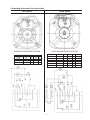
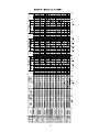
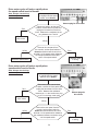
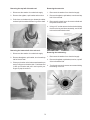
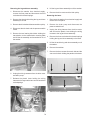
1
(/(&752/8;+20(352'8&76125 7+$0(5,&$ SERVICE MANUAL TOP LOAD WASHERS 2.7 & 3.0 Cu. Ft. Tubs :KLWH:HVWLQJKRXVH 5995377099 November 2002 1 SAFE SERVICING PRACTICES - ALL APPLIANCES To avoid personal injury and/or property damage, it is important that Safe Servicing Practices be observed. The following are some limited examples of safe practices: 1. DO NOT attempt a product repair if you have any doubts as to your ability to complete it in a safe and satisfactory manner. 2. Before servicing or moving an appliance: Remove the power cord from the electrical outlet, trip the circuit breaker to the OFF position, or remove the fuse. Turn off the gas supply. Turn off the water supply. 3. Never interfere with the proper operation of any safety device. 4. USE ONLY REPLACEMENT PARTS CATALOGED FOR THIS APPLIANCE. SUBSTITUTIONS MAY DEFEAT COMPLIANCE WITH SAFETY STANDARDS SET FOR HOME APPLIANCES. 5. GROUNDING: The standard color coding for safety ground wires is GREEN, or GREEN with YELLOW STRIPES. Ground leads are not to be used as current carrying conductors. It is EXTREMELY important that the service technician reestablish all safety grounds prior to completion of service. Failure to do so will create a hazard. 6. Prior to returning the product to service, ensure that: All electrical connections are correct and secure All electrical leads are properly dressed and secured away from sharp edges, high-temperature components, and moving parts All non-insulated electrical terminals, connectors, heaters, etc. are adequately spaced away from all metal parts and panels All safety grounds (both internal and external) are correctly and securely connected All panels are properly and securely reassembled ATTENTION!!! This service manual is intended for use by persons having electrical and mechanical training and a level of knowledge of these subjects generally considered acceptable in the appliance repair trade. Electrolux Home Products cannot be responsible, nor assume any liability, for injury or damage of any kind arising from the use of this manual. © 2001 White Consolidated Industries 2 SAFE SERVICING PRACTICES QUICK REFERENCE SHEET Serial nameplate location Serial number breakdown Tech sheet location Specification Connecting drive motor for bench check SAMPLE WIRING DIAGRAM SAMPLE TIMER CHART SECTION A - OPERATING INSTRUCTIONS Before operating your washer Operating steps Cycle selection Whites cycle Extra rinse cycle Colors cycle Knits & delicates cycle Soak & prewash cycle Soak Prewash Power scrub option Automatic extra rinse option Controls Agitate/spin speeds Wash/rinse temperature Precision temp control Load size Energy saving tips SECTION B - OWNERS GUIDE Safety information For your safety Product registration Important safety instructions Prevent fire Protect children Prevent injury Washing procedures Sorting laundry Prepare items for washing Pretreat stains and heavy soil Adding detergent Adding liquid bleach Adding laundry Adding liquid fabric softener For models with a removable dispenser For models without a fabric softener dispenser Set cycle selector knob and washer controls Start the washer Remove items when the cycle is completed Stain removal Safe stain removal procedures For successful stain removal Stain removal chart Common washing problems Care and cleaning 3 2 7-9 7 7 7 8 9 10 11 12 - 14 12 12 12 12 12 12 13 13 13 13 13 13 - 14 13 14 14 14 14 14 15 - 29 15 - 16 15 15 15 15 15 16 17 - 19 17 17 17 18 18 18 18 19 19 19 19 19 19 - 21 19 20 20 - 21 22 - 23 24 Inside Outside Winterizing instructions Avoid service checklist Sample warranty USA Service information (Canada) Sample warranty Canada SECTION C - INSTALLATION INSTRUCTIONS Full size automatic washer Pre-installation requirements Tools required for installation Electrical reqirement Circuit Power supply Outlet receptacle Grounding requirements Water supply requirements Drain requirements Rough-in dimensions Location of your washer Do not install your washer Unpacking Installation Replacement parts United States Canada SECTION D - PARTS LOCATION AND THEIR FUNCTION Timer Speed combination switch Sample timer cycle chart Pressure switch assembly Wash cycle options switch Wash/rinse temperature switch Auto temp system The end of cycle signal switch The end of cycle signal Lid lock assembly Softener dispenser Agitator Bleach dispenser Water inlet valve Valve operation Drain pump The motor Transmission Spin basket or inner tub Splash tub cover Outer tub Leg and dome assembly Snubber Base SECTION E - ELECTRICAL OPERATION Option switch circuits Line switch circuit Fill circuit During the wash cycle 4 24 24 24 25 - 26 27 28 29 30 - 33 30 30 30 30 30 30 30 30 30 31 31 31 31 31 32 33 33 33 34 - 42 34 34 35 36 36 36 37 37 37 38 38 38 38 39 39 40 40 40 41 42 42 42 42 42 43 - 46 43 44 44 - 45 44 Spray rinse during the first pump cycle During the rinse cycle Drive motor circuit Motor in agitation cycle Motor in spin cycle SECTION F - TROUBLESHOOTING FLOW CHARTS Washer completely inoperative Timer does not advance Washer does not drain Drive motor operates in spin but not in agitation Drive motor does not turn Drive motor operates in agitation but not in spin Slow water fill Drive motor cycles off and on rapidly when the speed switch set to normal Drive motor cycles off and on rapidly when the speed switch set to gentle Drive motor cycles off and on rapidly when the speed switch set to ex. gentle Auto temp control does not control the wash water temperature within specifications Water fill does not turn off Incorrect water level Washer will not fill in any setting of the temperature selector sw Washer will not fill in wash cycle, but will fill in rinse with the temp switch set to cold/cold Washer will only fill with cold water in the wash cycle, with the temp switch set to warm/cold Water temperature is too hot or too cold in the wash cycle with the temp sw. set to warm/warm Washer will only fill with hot water in the wash cycle, with the temp switch set to warm/cold but does fill with cold water in the rinse cycle SECTION G - TEARDOWN Removing the knobs Timer knob (some models) Timer knob (some models) Timer skirt (some models) Timer skirt (some models) All other knobs Raising the top Removing the rear panel from console Removing the timer (some models) Removing the timer (some models) Removing the speed switch, option switch or temp switch Removing the end of cycle signal Removing the end of cycle signal switch Removing the pressure switch assembly Removing the electronic moisture sensor control Removing the front closure Removing the console Removing the end caps Removing the consoles front panel Removing the lid lock assembly Removing the lid hinges Removing the lid spring Removing the lid Removing the water inlet nozzle assembly Removing the bleach dispenser Replacing the top 5 45 46 47 - 50 47 - 48 49 - 50 51 - 61 52 52 53 53 54 55 55 56 56 57 57 58 58 59 60 60 61 61 62 - 79 62 62 62 62 63 63 63 63 64 64 64 65 65 66 66 66 67 67 68 68 68 69 69 69 69 70 Removing the top hinges Removing the water inlet valve Alternate water valve attachment Removing the ATC sensor Removing the front panel Removing the drain pump Disassembling the drain pump Removing the softener dispenser Removing the mechanism cap Reinstalling the mechanism cap Removing the agitator Removing the drive hub Removing the splash tub cover Removing the spin basket Removing the trunnion Removing the top half of the tub seal Removing the bottom half of the tub seal Removing the outer tub Removing the tub bearing Removing the drive belt Removing the transmission pulley Removing the transmission Replacing the vertical springs Removing the idler pulley assembly Removing the snubber Removing the drive motor shield Removing the start capacitor Removing the drive motor Removing the leg and dome assembly Removing the base 70 70 70 71 71 71 72 72 72 73 73 73 74 74 74 75 75 75 75 76 76 76 76 77 77 77 78 78 79 79 6 QUICK REFERENCE SHEET 1. Serial nameplate location: On the under side of the lid, in the top right-hand corner. X C 2 0 7 0 1 3 8 8 2. Serial number breakdown. Incremented unit number Production week Last digit of production year Product identification Manufacturing facility 3. Tech sheet location Inside the console 7 Specifications Washer Transmission Agitate Speed Oscillations Per Minute (High) Agitate Speed Oscillations Per Minute (Low) Agitate Speed Oscillations Per Minute (Gentle) Spin Speed R.P.M. (High Speed) Spin Speed R.P.M. (Low Speed) Oil Capacity (Ounces) Motor Motor HP @ 120V, 60Hz. (Min OP - 100V Internal Thermal Overload Protection, Capacitor Start (189 - 210 Mfd., 135 Volt) One Speed (RPM) Two Speed (RPM) Three Speed (RPM) Agitate Agitate Wattage - Full Load (High Speed) Max. Agitate Wattage - Full Load (Low Speed) Max. Agitate Wattage - Full Load (Ex. Low Speed) Max. Spin Full Spin Wattage - No Load (High Speed) Full Spin Wattage - No Load (Low Speed) Spin Wattage - No Load (High Speed) Max. After 10 Sec. Spin Wattage - No Load (High Speed) Max. After 10 Sec. Full Spin Wattage - Full Load (High Speed) Full Spin Wattage - Full Load (Low Speed) Spin Wattage - Full Load (High Speed) Max. After 10 Sec. Spin Wattage - Full Load (High Speed) Max. After 10 Sec. Tub Capacity / Water Usage Capacity (Cu. Ft.) Water Level (Inches) Measured from tub bottom Large Small Water Supply Pressure (P.S.I.) Minimum/Maximum Water Flow Rate (G.P.M.) Drain Pumpout G.P.M. @ 36 (Min.) G.P.M. @ 96 (Min.) Agitator Clearance Agitator Bottom to Tub Component resistance - Ohms +/- 10% @ 77°F Motor 4 Pole Main Winding (High Speed) 6 Pole Main Winding (Low Speed) If 2 Speed Motor Fill Valve Hot Water Solenoid Cold Water Solenoid Timer Motor Pump Motor - Ohms +/- 7% @ 68°F ATC - Ohms +/- 2% @ 77°F 8 2.7 Cu. Ft. tub 3.0 Cu. Ft. tub 71 - 77 47 - 51 33 - 37 600 - 640 390 - 420 32 71 - 77 47 - 51 33 - 37 600 - 640 390 - 420 32 1/2 & 3/4 1/2 & 3/4 1725 1150/1725 840/1150/1725 1725 1150/1725 840/1150/1725 750 450 950 475 475 300 - 660 250 - 575 800 700 300 - 660 250 - 575 900 700 300 - 660 250 - 575 800 700 300 - 660 250 - 575 900 700 2.7 10.8 - 13.0 4.3 - 6.6 3.0 13.5 - 15.2 5.5 - 7.8 30/120 3 - 14.6 30/120 3 - 14.6 12 7 12 7 .050 - .300 .050 - .300 2.4 1.5 2.4 1.5 880 880 2322 12 50000 880 880 2322 12 50000 Connecting drive motor for bench check Two Speed Three Speed ROTATION GIVEN VIEWING LEAD END ROTATION GIVEN VIEWING LEAD END ROTATION CCW CCW CW CW SPEED HI LO HI LO L1 3 3 3 3 L2 6,1 2,1 6,5 2,5 ROTATION SPEED CCW HI CCW LO CCW EX. LO CW HI CW LO CW EX. LO 7 5 5 1 1 9 L1 3 3 3 3 3 3 L2 6,1 2,1 2,1 6,5 2,5 2,5 7 5 5 5 1 1 1 8 -W/OR W/V -W/OR W/V Caution: Disconnect Electrical Current Before Servicing 10 11 SECTION A - OPERATING INSTRUCTIONS WASH/RINSE TEMPERATURE WARM WARM EXTRA RINSE COLD * COLD COLD COLD WASH CYCLE OPTIONS POWER SCRUB POWER SCRUB / EXTRA RINSE WARM * COLD WARM COLD OFF GENTLE NORMAL MEDIUM SMALL SOAK & PREWASH WASH / SPIN SPEEDS LOAD SIZE SUPER RESET EXTRA GENTLE GENTLE NORMAL NORMAL WARM * WARM HOT COLD OFF * REGULAR / WHITES 8 RINSE POWER SPIN POWER SCRUB /SOAK EXTRA RINSE SPIN RINSE HAND WASH CYCLE SIGNAL ON 15 12 PREWASH GENTLE GENTLE KNITS/DELICATES PRECISION TEMP CONTROL 6 PULL TO START Versión en español Si desea obtener una copia en español de estas Instrucciones de Funcionamiento, sírvase escribir a la dirección que se incluye a continuación. Solicite la P/N 134108600. Spanish Owner's Guides Electrolux Home Products P. O. Box 212378 Augusta, GA 30917 Before Operating Your Washer Read your washer Owner's Guide. It has important safety and warranty information. It also has many suggestions for best washing results. To reduce the risk of fire, electric shock, or injury to persons, read the IMPORTANT SAFETY INSTRUCTIONS in your washer Owner's Guide before operating this appliance. Operating Steps Read Washing Procedures in your Owner's Guide. It explains these operating steps in detail. 7. If desired, add liquid fabric softener to Fabric Softener Dispenser. 8. Set cycle selector and washer controls according to type, size, and soil level of each load. 12 PERM PRESS / COLORS PUSH TO STOP Cycle Selection Always follow instructions on fabric care labels. The Whites, Colors, and Knits & Delicates cycles provide a spray rinse during the first spin, followed by a deep rinse and final spin. Whites Cycle Provides up to 15 minutes of wash agitation for most fabrics. Power Spin provides 12 minutes of spin at a selected speed for maximum removal of water. This conserves energy by reducing drying time. Extra Rinse Cycle Use Extra Rinse to remove excess dirt and detergent from heavily soiled loads. Extra Rinse provides 3 minutes of rinse agitation, then a 9 minute spin. Select Automatic Extra Rinse under Wash Cycle Options to automatically advance to Extra Rinse after the Whites cycle is completed. Select Automatic Power Scrub/Extra Rinse under Wash Cycle Options to automatically advance to Extra Rinse after the Soak & Prewash and Whites cycles are completed. 5. If desired, add liquid bleach to Bleach Dispenser. 6. Add laundry load to wash tub. 8 10. Remove items at end of cycle. A signal will sound at the end of the cycle when the End of Cycle Signal is turned on. Wait about 1 minute for safety lid lock to release. 3. Pretreat stains and heavy soil. 4. Add the measured amount of detergent to wash tub. 4 9. Close lid and pull cycle selector knob to start washer. 1. Sort laundry into loads that can be washed together. 2. Prepare items for washing. PERM PRESS PREWAS Colors Cycle Provides 12 minutes of wash agitation for light weight cottons, 8 minutes of wash agitation for items with a noiron finish or 4 minutes of wash agitation for knits. 12 Knits & Delicates Cycle Provides 6 minutes of wash agitation for delicate items or 3 minutes of wash agitation for hand washables. Soak & Prewash Cycle from the Soak or Prewash setting into the Whites wash and Extra Rinse cycles. 1. Add the measured amount of detergent to wash tub, then add wash load. 2. Select appropriate Wash/Rinse Temperature, Load Size, and Agitate/Spin Speed. Soak Use Soak to treat heavily soiled or stained items. Soak provides 3 minutes of agitation and 12 minutes of soaking time. The load then advances into the Prewash portion of the cycle. Use the amount of detergent recommended for a normal wash cycle. If desired, use bleach or a soaking agent for colorfast items. The Soak water temperature is the same as the rinse water temperature selected. Select the Agitate/Spin Speed appropriate for the items being soaked. Select Wash Cycle Option OFF if advancing into the Whites cycle is not desired. Follow Soak with a complete wash cycle using the normal amount of detergent. Prewash Use Prewash when soaking is not necessary. Prewash helps remove protein-based stains such as milk, grass and blood. It also helps loosen soils before washing. Prewash provides 3 minutes of wash agitation. Use the amount of detergent recommended for a normal wash cycle. The Prewash water temperature is the same as the wash water temperature selected. To avoid setting protein stains, select cold water. Select the Agitate/Spin Speed appropriate for the items being prewashed. Select Wash Cycle Option OFF if advancing into the Whites cycle is not desired. Follow Prewash with a complete wash cycle using the normal amount of detergent. Power Scrub Option Select Power Scrub to automatically advance a load 13 3. Select Power Scrub under Wash Cycle Options. To use a cycle other than Whites after the Soak or Prewash settings, select OFF and manually advance cycle selector to cycle desired. 4. Fill fabric softener dispenser with the recommended amount of LIQUID detergent. Add water to bring liquid level to fill line on dispenser cap. When selecting Power Scrub, the fabric softener dispenser must be filled with diluted liquid detergent at the beginning of the Soak or Prewash setting. The detergent for the Whites cycle will then be dispensed after the spin in Prewash. DO NOT use powdered detergent in the dispenser. Clean the fabric softener dispenser thoroughly after each use. Fabric softener and liquid detergent should not be mixed. 5. Set the cycle selector at Soak or Prewash and pull knob to start. The washer will provide Soak or Prewash as selected. It then automatically advances to the full Whites and Extra Rinse cycles. Automatic Extra Rinse Option Select Automatic Extra Rinse or Power Scrub/Extra Rinse to provide an extra rinse at the end of the Whites cycle. Controls Always follow instructions on fabric care labels. AGITATE/SPIN SPEEDS offers three agitation speeds and four combinations of agitation and spin speeds for any cycle. The following chart suggests agitate/spin speeds for basic fabric types. Fabric Type Agitate/Spin Speed Regular Normal/Normal Perm Press Normal/Normal Knits Gentle/Normal Delicates / Washable woolens Gentle/Gentle Hand washables Extra Gentle/Gentle WASH/RINSE TEMPERATURE sets water temperatures for washing and rinsing. Select wash water temperature according to fiber content, soil level and type of detergent. A cold water rinse saves energy and reduces wrinkling. Precision Temp Control The normal temperature of warm and cold wash water can be affected by the hot water heater setting and seasonally low ground water temperatures in some geographic areas. Since detergents work best in wash water at a minimum of 65° F, select a Precision Temp to regulate the temperature of the warm and cold wash water in any cycle. Wash water in the Precision Temp Warm/Cold and Precision Temp Warm/Warm settings is regulated to approximately 90° F. and the wash water in the Precision Temp Cold/Cold setting is regulated to approximately 70° F. Rinse water temperatures are not regulated. When small wash loads cannot be avoided, use lower water levels. Select the appropriate cycle and time for each load. Shorten wash times for lightly soiled loads. To reduce drying time, select a fast spin speed to remove more water from heavy items such as towels and jeans. Use warm water to wash most loads. Limit hot water washes to heavily soiled and white loads. Use cold water for lightly soiled items and rinsing. Operate the washer in early morning and late evening when utility demands are low. Follow proper laundry procedures to avoid rewashing. The following chart suggests wash/rinse temperatures for some typical wash loads. Fabric Type Wash/Rinse Temperature Heavily soiled white/colorfast cotton, perm press Hot/Cold Lightly soiled white/colorfast cotton, perm press Warm/Cold * Noncolorfast fabrics, knits, delicates, hand washables Washable woolens Cold/Cold * Warm/Warm * * unregulated or Precision Temp Control LOAD SIZE sets the amount of wash and rinse water for the wash load. Select a water level appropriate for the load size. There should be enough water for items to move freely. To increase water level after the wash cycle begins, turn the Load Size control to Reset and hold. When water begins to enter the tub, turn the control to the desired setting. Energy Saving Tips Wash full loads. Oversize loads use extra energy. Undersize loads waste energy. 14 SECTION B - OWNERS GUIDE waxes, etc. Do not store these items on or near the washer. These substances give off vapors or chemical reactions that could ignite or explode. Product Registration Do not put oily or greasy rags or clothing on top of the washer. These substances give off vapors that could ignite the materials. Thank you for choosing this washer. This owner's guide will explain proper operation and care. Record Your Model and Serial Numbers Record below the model and serial numbers found on the washer serial plate located on the underside of the washer lid. Keep these numbers for future reference. Do not add gasoline, cleaning solvents, or other flammable or explosive substances to the wash water. These substances give off vapors that could ignite or explode. Model Number ________________ Under certain conditions, hydrogen gas may be produced in a hot water system that has not been used for 2 weeks or more. HYDROGEN GAS IS EXPLOSIVE. If the hot water system has not been used for such a period, before using the washer, turn on all hot water faucets and let the water flow from each for several minutes. This will release any accumulated hydrogen gas. Hydrogen gas is flammable; do not smoke or use an open flame during this time. Serial Number _________________ Date of Purchase ________________ Register Your Product The self-addressed PRODUCT REGISTRATION CARD should be filled in completely, signed and returned. This Owner's Guide provides general operating instructions for your washer. It also contains information about features for several other models. Your washer may not have every feature included here. Use the washer only as instructed in this Owner's Guide and the Operating Instructions card included with your washer. FOR YOUR SAFETY Do not store or use gasoline or other flammable vapors or liquids in the vicinity of this or any other appliance. Failure to comply with these warnings could result in fire, explosion, serious bodily injury and/or damage to the rubber or plastic parts of the washer. Protect Children Do not allow children to play on or in the washer. Close supervision of children is necessary when the washer is used near children. As children grow, teach them the proper, safe use of all appliances. Destroy the carton, plastic bag and other packing materials after the washer is unpacked. Children might use them for play. Cartons covered with rugs, bedspreads or plastic sheets can become airtight chambers. Important Safety Instructions Read all instructions before using this washer. To reduce the risk of fire, electrical shock, or injury to persons when using this washer, comply with the basic warnings listed below. Failure to comply with these warnings could result in serious personal injuries. Prevent Fire Do not wash items that have been previously cleaned in, soaked in, or spotted with gasoline, cleaning solvents, kerosene, cooking oils, 15 Keep laundry products out of children's reach. To prevent personal injury, observe all warnings on product labels. Before the washer is removed from service or discarded, remove the washer lid to prevent accidental entrapment. Failure to comply with these warnings could result in serious personal injuries. Avoid fire hazard or electrical shock. Do not use an adaptor plug or extension cord or remove grounding prong from electrical power cord. Failure to follow this warning can cause serious injury, fire or death. must be plugged into a properly grounded and polarized 3-prong outlet. The third grounding prong must never be removed. Never ground the washer to a gas pipe. Do not use an extension cord or an adaptor plug. Follow package directions when using laundry products. Incorrect usage can produce poisonous gas--resulting in serious injury or death. CORRECT Use this way ONLY Do not use or mix liquid chlorine bleach with other household chemicals such as toilet cleaners, rust removers, acid or products containing ammonia. These mixtures can produce dangerous fumes which can cause serious injury or death. Do not combine laundry products for use in 1 load unless specified on the label. Do not mix chlorine bleach with ammonia or acids such as vinegar. To prevent serious personal injury and damage to the washer: All repairs and servicing must be performed by an authorized servicer unless specifically recommended in this Owner's Guide. Use only authorized factory parts. Do not tamper with controls. Do not install or store the washer where it will be exposed to the weather. ALWAYS disconnect the washer from the electrical supply before attempting any service or cleaning. Failure to do so can result in electrical shock or injury. Note: The instructions appearing in this Owner's Guide are not meant to cover every possible condition and situation that may occur. Common sense and caution must be practiced when installing, operating and maintaining any appliance. Prevent Injury To prevent shock hazard and assure stability during operation, the washer must be installed and electrically grounded by a qualified service person in accordance with local codes. Installation instructions are packed in the washer for installer's reference. Refer to INSTALLATION INSTRUCTIONS for detailed grounding procedures. If the washer is moved to a new location, have it checked and reinstalled by a qualified service person. To prevent injury, do not reach into the washer while parts are moving. Before loading, unloading or adding items, push in the cycle selector knob and allow the tub to coast to a complete stop before reaching inside. Failure to comply with these warnings could result in serious personal injuries. This washer is equipped with an electrical overload protector. The motor will stop if it becomes overheated. The washer will automatically restart after a cool down period of up to 30 minutes, if the washer has not been manually turned off during this time. SAVE THESE INSTRUCTIONS To prevent personal injury or damage to the washer, the electrical power cord of the washer 16 Washing Procedures Follow the guidelines below for preparing the wash load. Read the Operating Instructions card for operating your specific model. Always read and follow fabric care and laundry product labels. 2. Prepare items for washing. Empty pockets. To reduce the risk of fire, electrical shock, or injury to persons, read Important Safety Instructions, before operating this washer. Empty pockets. 1. Sort laundry into loads that can be washed together. Sort items by recommended water temperatures, wash time, and agitate/spin speeds. Brush off lint and dirt. Shake out rugs and beach towels. Close zippers, fasten hooks, tie strings and sashes, and remove nonwashable trims and ornaments. Separate white, light, and colorfast items from dark and noncolorfast items. Separate items which shed lint from items which attract lint. Permanent press, synthetic, knit and corduroy items will pick up lint from towels, rugs and chenille bedspreads. Remove pins, decorative buttons, belt buckles, and other objects which could be damaged. This also helps protect other items in the wash load. Separate heavily soiled items from lightly soiled items. Mend rips and tears to prevent further damage during washing. Separate lacy, sheer and loosely knit items from sturdy items. Place delicate items such as bras, shoulder pads, hosiery, and belts in a mesh bag to prevent tangling during the wash cycle. Place delicate items in a mesh bag. Sort laundry into loads that can be washed together. Turn knit items inside out to prevent pilling. 3. Pretreat stains and heavy soil. See Stain Removal. 4. Add a measured amount of detergent to the wash tub before adding the laundry load. Follow detergent manufacturer's directions. The 17 amount required depends on type of detergent, load size and soil level, and water hardness. 5. If desired, add liquid bleach to Bleach Dispenser (some models). Before adding the wash load, add liquid bleach to bleach dispenser located in left front corner under the lid: 3/4 cup (180 ml) for small loads 1 cup (240 ml) for large loads 1-1/4 cups (300 ml) for extra-large loads. When washing a single heavy item, add 1 or 2 towels to balance the load. Then add 1 cup (240 ml) water to flush the dispenser. Built-In Fabric Softener Dispenser (some models) 1. Add liquid softener to the dispenser, following fabric softener label directions. Do not use powdered bleach in the bleach dispenser. 2. Add water to bring liquid level to fill line on dispenser cap. 3. Remove the dispenser from the agitator after each use. Rinse both cap and cup with warm water. Replace dispenser in the agitator. 6. Add laundry load to washer. NOTE: To separate cap from cup, put thumb into dispenser and push against side of cup. Dry load level should not be higher than top row of holes in wash tub. Do not load items above top row of holes in wash tub. Built-In Fabric Softener Dispenser(some models) Do not overload washer. For models with a built-in dispenser For models without a bleach dispenser, dilute the recommended amount of liquid chlorine bleach in 1 quart (.95 L) water. Add it to wash water after a few minutes of agitation. Do not pour bleach directly on wash load. Combine large and small items in a load. Load large items first. Large items should not be more than half the total wash load. 7. If desired, add liquid fabric softener to Fabric Softener Dispenser (some models). Bleach Dispenser (some models) After cleaning, push cap and cup firmly together. Replace dispenser by lining up the ribs and grooves and snapping it into position. Do not put items on top of agitator or wrap them around it. Load items evenly. 18 Fabric softener will be flushed from area under the built-in fabric softener dispenser when Large Load Water Level is selected. If a build-up of fabric softener occurs, clean with hot water. DO NOT REMOVE SERVICE CAP. 10. Remove items when the cycle is completed. For your safety, the lid locks when the tub is spinning. It will remain locked for about 1 minute after the tub stops spinning. For models with a removable dispenser: 1. Attach fabric softener dispenser to top of agitator by pressing down gently. To open the lid during a spin, push in the cycle selector knob and wait about 1 minute for the lid lock to release. Do not force open the locked lid. 2. Add softener to the dispenser, following fabric softener label directions. Place washed items in automatic dryer, line dry, or dry flat as directed by fabric care label. Excess wrinkling, color transfer or odors may develop in items left in the washer after the cycle has ended. Removable Fabric Softener Dispenser (some models) 3. Add water to bring liquid level to top of the peg in the center of the cup. To avoid serious personal injury, do not operate washer if safety lid lock is missing or damaged. 4. Remove the dispenser from the agitator after each use. Rinse both lid and bowl thoroughly with warm water. Reassemble and place dispenser on agitator or store it nearby. Stain Removal For models without a fabric softener dispenser, follow fabric softener label directions. Add diluted fabric softener to the final rinse. Do not pour fabric softener directly on the wash load 8. Set cycle selector knob and washer controls according to type, size, and soil level of each load, and detergent used. 9. Start the washer. Close the washer lid and pull out the cycle selector knob. Washer will fill with the lid open. The tub will not agitate or spin unless the lid is closed. To stop the washer, push in the cycle selector knob. Do not stop and restart washer during a spin when using the fabric softener dispenser. To change a cycle, push in the cycle selector knob. Turn it clockwise to the desired setting. Pull out the knob to restart the washer. 19 Safe Stain Removal Procedures To reduce the risk of fire or serious injury to persons or property, comply with the basic warnings listed below: Read and comply with all instructions on stain removal products. Keep products in their original labeled containers and out of children's reach. Thoroughly wash any utensil used. Do not combine stain removal products, especially ammonia and chlorine bleach. Dangerous fumes may result. Do not combine stain removal products. Never wash items which have been previously cleaned in, washed in, soaked in or spotted with gasoline, dry cleaning solvents or other flammable or explosive substances because they give off vapors that could ignite or explode. Use cold water on unknown stains because hot water can set stains. Check care label instructions for treatments to avoid on specific fabrics. Never use highly flammable solvents, such as gasoline, inside the home. Vapors can explode on contact with flames or sparks. For successful stain removal: Remove stains promptly. Determine the kind of stain, then follow recommended treatment in the stain removal chart on the next page. To pretreat stains, use a prewash product, liquid detergent, or a paste made from granular detergent and water. Follow fabric care label instructions. Check for colorfastness by testing stain remover on an inside seam. Rinse and wash items after stain removal. Stain Removal STAIN TREATMENT Adhesive tape, chewing gum, rubber cement. Apply ice. Scrape off excess. Place stain face down on paper towels. Saturate with prewash stain remover or nonflammable dry cleaning fluid. Baby formula, dairy products, egg. Use product containing enzymes to pretreat or soak stains. Soak for 30 minutes or more. Wash. Beverages (coffee, tea, soda,juice, alcoholic beverages). Pretreat stain. Wash using cold water and bleach safe for fabric. Blood. Rinse with cold water. Rub with bar soap. Or, pretreat or soak with product containing enzymes. Wash using bleach safe for fabric. Candle wax, crayon. Scrape off surface wax. Place stain face down between paper towels. Press with warm iron until wax is absorbed. Replace paper towels frequently. Treat remaining stain with prewash stain remover or nonflammable dry cleaning fluid. Hand wash to remove solvent. Wash using bleach safe for fabric. Chocolate. Pretreat or soak in warm water using product containing enzymes. Wash using bleach safe for fabric. Collar or cuff soil, cosmetics. Pretreat with prewash stain remover or rub with bar soap. Dye transfer on white fabric. Use packaged color remover. Wash using bleach safe for fabric. Grass. Pretreat or soak in warm water using product containing enzymes. Wash using bleach safe for fabric. 20 STAIN TREATMENT Grease, oil, tar (butter, fats,salad dressing, cooking oils, car grease, motor oils). Scrape residue from fabric. Pretreat. Wash using hottest water safe for fabric. For heavy stains and tar, apply nonflammable dry cleaning fluid to back of stain. Replace towels under stain frequently. Rinse thoroughly. Wash using hottest water safe for fabric. Ink. Some inks may be impossible to remove. Washing may set some inks. Use prewash stain remover, denatured alcohol or nonflammable dry cleaning fluid. Mildew, scorch. Wash with chlorine bleach if safe for fabric. Or, soak in oxygen bleach and hot water before washing. Badly mildewed fabrics may be permanently damaged. Mud. Brush off dry mud. Pretreat or soak with product containing enzymes. Mustard, tomato. Pretreat with prewash stain remover. Wash using bleach safe for fabric. Nail polish. May be impossible to remove. Place stain face down on paper towels. Apply nail polish remover to back of stain. Repeat, replacing paper towels frequently. Do not use on acetate fabrics. Paint, varnish. WATER BASED: Rinse fabric in cool water while stain is wet. Wash. Once paint is dry, it cannot be removed. OIL BASED AND VARNISH: Use solvent recommended on can label. Rinse thoroughly before washing. Perspiration. Use prewash stain remover or rub with bar soap. Rinse. Wash using nonchlorine bleach in hottest water safe for fabric. Rust, brown or yellow discoloration. For spots, use rust remover safe for fabric. For discoloration of an entire load, use nonchlorine bleach. Do not use chlorine bleach because it may intensify discoloration. Shoe polish. LIQUID: Pretreat with a paste of granular detergent and water. PASTE: Scrape residue from fabric. Pretreat with prewash stain remover or nonflammable dry cleaning fluid. Rinse. Rub detergent into dampened area. Wash using bleach safe for fabric. Urine, vomit, mucus, feces. Pretreat or soak in product containing enzymes. Wash using bleach safe for fabric. 21 Common Washing Problems Many washing problems involve poor soil and stain removal, residues of lint and scum, and fabric damage. For satisfactory washing results, follow these suggestions provided by The Soap and Detergent Association. PROBLEM POSSIBLE CAUSES SOLUTIONS PREVENTIVE MEASURES Detergent or liquid fabric softener did not dissolve or disperse. If caused by detergent, mix 1 cup (240 ml) white vinegar with 1 quart (.95 L) water in a plastic container. Soak item 1 hour. Rinse. If caused by fabric softener, rub stains with bar soap. Wash. Add detergent before wash load. Then start washer. Discoloration, graying Not enough detergent. Wash water temperature too low. Incorrect sorting. Rewash with correct amount of detergent and hottest water safe for fabric. Add bleach safe for fabric. Sort items by soil level and color. Use correct amount of detergent, hottest water and bleach safe for fabric. Greasy, oily stains Not enough detergent. Undiluted liquid fabric softener poured directly on fabric. Treat with prewash stain remover or liquid detergent. Increase detergent and water temperature. Rewash. Rub fabric softener stains with bar soap. Use correct amount of detergent and hottest water safe for fabric. Do not pour liquid fabric softener directly on fabric. See package directions or Washing Procedures for proper diluting. Holes, tears, or snags Incorrect use of chlorine bleach. Unfastened zippers, hooks, buckles. Rips, tears and broken threads. Overloading the washer. Degradation of fabric. May be irreversible if rips, tears and seams cannot be mended. Never pour chlorine bleach directly on fabric. Check condition of items before washing. See Washing Procedures for preparing and loading the wash load. Lint Incorrect sorting. Tissues left in pocket. Overloading the washer. Not enough detergent. Undissolved detergent has left residue. Static cling is attracting lint. Load washed too long. Reduce load size. Rewash using correct water temperature, water level, and amount of detergent. Add nonprecipitating water conditioner to wash water. Add liquid fabric softener to final rinse. Dry load in dryer. Remove lint with lint brush or roller. See Washing Procedures for sorting and preparing the wash load. Do not overload washer. Use correct amount of detergent, water temperature and water level. Blue stains 22 Dilute fabric softener with water. Common Washing Problems Many washing problems involve poor soil and stain removal, residues of lint and scum, and fabric damage. For satisfactory washing results, follow these suggestions provided by The Soap and Detergent Association. PROBLEM POSSIBLE CAUSES Pilling is normal with Pilling synthetic and permanent (Fibers break off, ball up and cling to press fabrics. This is due to abrasion from normal fabric) wear. SOLUTIONS Use a lint brush or shaver to remove pills. PREVENTIVE MEASURES Use fabric softener in the washer to lubricate fibers. When ironing, use spray starch or fabric finish on collars and cuffs. Turn items inside out to reduce abrasion. Residue or powder on dark items; Stiff, harsh fabrics. Undissolved detergent. Some nonphosphate granular detergents can combine with hard water minerals to form a residue. Increase water temperature Reduce load size. using hottest water safe for Add dissolved detergent fabric. to tub . Rewash load. Mix 1 cup (240 ml) white Do not overload washer. vinegar to 1 gallon (3.8 L) Use liquid detergent or use nonprecipitating water warm water in plastic conditioner with container. Soak item. nonphosphate granular Rinse and rewash. detergent. Wrinkling Overloading the washer. Reduce load size. Rinse in cold water with liquid fabric softener. Yellow buildup of Agitation time too short. Wash water temperature body soil on too low. synthetic fabrics Not enough detergent. Yellow or brown rust stains Do not overload washer. Remove items from washer as soon as cycle is completed. Use liquid fabric softener. Soak in detergent booster Wash synthetics frequently using water at least 100°F or product containing (37°C ) and correct water enzymes. Wash in hot water (120°F/ level. 49°C) using full permanent press cycle. Increase detergent. Add bleach safe for fabric. Or, treat with color remover. Iron or manganese in To restore discolored load Use nonprecipitating water softener. water supply, water pipes, of whites, use rust Before washing, run hot or water heater. remover safe for fabric. water for a few minutes to Do not use chlorine clear lines. bleach to remove rust stains. It may intensify Drain water heater occasionally. discoloration. For an ongoing problem, install an iron filter in your water supply system. 23 Care and Cleaning Use care with laundry products. They can damage finish on the washer. Before moving the washer, place a strip of cardboard or thin fiberboard under the front leveling legs to prevent floor damage. Follow Winterizing Instructions for cold weather care. Inside Remove items from the washer as soon as the cycle ends. Excess wrinkling, color transfer, and odors may develop in items left in the washer. Dry the washer top, the area around the lid opening, and the underside of the lid. These areas should always be dry before the lid is closed. Before cleaning the washer interior, unplug the electrical power cord to avoid electrical shock hazards. When extremely soiled items have been washed, a dirty residue may remain on the tub. Remove this by wiping the tub with a nonabrasive household cleanser. Rinse thoroughly with water. The agitator or tub may become stained from fabric dye. Clean these parts with a nonabrasive household cleanser. This prevents dye transfer to future loads. Outside When washing is completed, wipe top and sides of washer with a damp cloth. Turn water faucets off to prevent pressure build-up in the hoses. As needed, clean the cabinet with mild soap and water. Never use harsh, gritty or abrasive cleansers. If top or lid becomes stained, clean with diluted chlorine bleach [1/2 cup (120 ml) in 1 quart (.95 L) water]. Rinse several times with clear water. Winterizing Instructions If the washer is stored in an area where freezing can occur or moved in freezing temperatures, follow these winterizing instructions to prevent damage to the washer: 1. Turn off water supply faucets. 2. Disconnect hoses from water supply and drain water from hoses. 3. Plug electrical cord into a properly grounded electrical outlet. 4. Add 1 gallon nontoxic recreational vehicle (RV) antifreeze to empty wash tub. Close lid. 5. Set cycle selector knob at a spin setting. Pull out knob and let washer spin for 1 minute to drain out all water. Not all of the RV antifreeze will be expelled. 6. Push in knob, unplug electrical power cord, dry tub interior, and close lid. 7. Store washer in an upright position. 8. To remove antifreeze from washer after storage, run empty washer through a complete cycle using detergent. Do not add wash load. Remove glue residue from tape or labels with a mixture of warm water and mild detergent. Or, touch residue with the sticky side of the tape or label. 24 Avoid Service Checklist Before calling for service, review this list. It may save both time and expense. The list includes common concerns that are not the result of defective workmanship or materials in this washer. OCCURRENCE NOISE "Clunking" sounds. or POSSIBLE CAUSE SOLUTION gear A certain amount of "clunking" or gear sounds are normal in a heavy-duty washer. This is normal. Rattling and clanking noise. Foreign objects such as coins or safety pins may be in tub or pump. Stop washer and check tub. If noise continues after washer is restarted, objects may be in pump. Call your authorized servicer. Belt buckles and metal fasteners are hitting wash tub. To prevent unnecessary noise and damage to tub, fasten fasteners and turn items inside out. Squealing sound or hot rubber odor. Washer is overloaded. Do not overload washer. Stop washer and reduce load. Thumping sound. Heavy wash loads may produce a thumping sound. This is usually normal. If sound continues, washer is probably out of balance. Stop washer and redistribute wash load. Vibrating noise. Washer is not resting firmly on floor. Move washer so it rests firmly on floor. Adjust leveling legs. See INSTALLATION INSTRUCTIONS for details. Shipping bolt and block have not been removed during installation. See INSTALLATION INSTRUCTIONS for removing shipping bolt and block. Wash load unevenly distributed in tub. Stop washer and rearrange wash load. Electrical power cord may not be plugged in or connection may be loose. Make sure plug fits tightly in wall outlet. House fuse blown, circuit breaker tripped, or a power outage has occurred. Reset circuit breaker or replace fuse. Do not increase fuse capacity. If problem is a circuit overload, have it corrected by a qualified electrician. If problem is a power outage, call local electric company. Water supply faucets are not turned on. Turn on water supply faucets. Cycle selector is not in correct position. Move indicator clockwise slightly. Pull out knob. Motor is overheated. Washer motor will stop if it becomes overheated. It will automatically restart after a cool down period of up to 30 minutes (if washer has not been manually turned off). OPERATING Washer does not start. 25 OCCURRENCE Washer won't spin. POSSIBLE CAUSE Lid is not completely closed. SOLUTION Residue left in tub. Heavily soiled items. Wipe tub with a nonabrasive household cleanser, then rinse. Shake or brush excess dirt and sand from items before washing. Wash load too wet after spin. Washer is overloaded. Do not overload washer. See Washing Procedures. Rearrange load to allow proper spinning. Straighten drain hose. Water does not enter washer or it enters slowly. Water supply is not adequate in area. Water supply faucets are not completely open. Water is being used elsewhere in the house. Close lid completely. Load is out of balance. Drain hose is kinked. Water inlet hoses are kinked. Water level does not cover load. Warm or hot water is not hot enough. Check another faucet in the house. Wait until water supply and pressure increase. Fully open hot and cold faucets. Water pressure must be at least 30 psi (260 kPa). Avoid running water elsewhere while washer is filling. Straighten hoses. Improper water level selection (for models with water level/load size control). Washer is overloaded. Select higher water level/load size. Hot water heater is set too low or is a distance from washer. Measure hot water temperature at nearby faucet with candy or meat thermometer. Water temperature should be at least 130°F (70°C). Adjust water heater as necessary. Avoid using hot water elsewhere before or during washer use. There may not be enough hot water available for proper cleaning. If problem persists, your hot water system may be unable to support more than 1 use at a time. Hot water is being used elsewhere in the house. Do not overload washer. When control is set at highest fill level, dry load level should not be higher than top row of circular holes in wash tub. Water in washer does not drain or drains slowly. Drain hose is kinked or clogged. Clean and straighten the drain hose. Water leaks. Fill hose connection at faucet or washer. House drain pipes are clogged. Oversudsing. Check and tighten hose connections. Install rubber sealing washers provided. Unclog drain pipes. Contact plumber if necessary. Use less detergent. Incorrect wash and rinse temperatures. Hot and cold water hoses are Connect hot water hose to hot water faucet and cold water hose to cold water faucet. Standpipe must be a minimum of 33" (83.82 cm) high to prevent siphoning. See INSTALLATION INSTRUCTIONS. Water is entering washer but tub does not fill. 26 FRIGIDAIRE GALLERY TOP LOAD WASHER WARRANTY SAMPLE WARRANTY ALWAYS USE THE WARRANTY (UNITED STATES) SUPPLIED WITH PRODUCTS Your Frigidaire product is protected by this warranty FRIGIDAIRE, THROUGH ITS AUTHORIZED SERVICERS, WILL: THE CONSUMER WILL BE RESPONSIBLE FOR: Pay all costs for repairing or replacing any parts of this appliance which prove to be defective in materials or workmanship. Costs of service calls that are listed under NORMAL RESPONSIBILITIES OF THE CONSUMER.* Provide a replacement for a defective or malfunctioning part found in the washer transmission (illustrated below). Costs for labor and replacement parts other than defective transmission parts. FULL 25-YEAR 25 years from original INNER WASH BASKET purchase date. WARRANTY (Excluding Alaska) Provide a replacement and in-home service labor, without charge, for an inner wash basket (illustrated below) that breaks due to defective materials or workmanship. Costs of service calls that are listed under NORMAL RESPONSIBILITIES OF THE CONSUMER.* LIMITED WARRANTY (Applicable to the State of Alaska) All of the provisions of the full and limited warranties above and the exclusions listed below apply. Costs of the technician's travel to the home and any costs for pick up and delivery of the appliance required because of service. WARRANTY PERIOD FULL ONE-YEAR WARRANTY LIMITED 2ND - 5TH YEAR WARRANTY One year from original purchase date. Second through fifth years from original purchase date. Time periods listed above. Your appliance is warranted by Frigidaire Home Products, a division of White Consolidated Industries, Inc. We authorize no person to change or add to any of our obligations under this warranty. Our obligations for service and parts under this warranty must be performed by Frigidaire or an authorized Frigidaire servicer. *NORMAL RESPONSIBILITIES OF THE CONSUMER This warranty applies only to products in ordinary household use, and the consumer is responsible for the items listed below: 1. Proper use of the appliance in accordance with instructions provided with the product. 2. Proper installation by an authorized servicer in accordance with instructions provided with the appliance and in accordance with all local plumbing, electrical and/or gas codes. 3. Proper connection to a grounded power supply of sufficient voltage, replacement of blown fuses, repair of loose connections or defects in house wiring. 4. Expenses for making the appliance accessible for servicing, such as removal of trim, cupboards, shelves, etc., which are not a part of the appliance when it was shipped from the factory. 5. Damages to finish after installation. 6. Replacement of light bulbs and/or fluorescent tubes (on models with these features). EXCLUSIONS This warranty does not cover the following: 1. CONSEQUENTIAL OR INCIDENTAL DAMAGES SUCH AS PROPERTY DAMAGE AND INCIDENTAL EXPENSES RESULTING FROM ANY BREACH OF THIS WRITTEN OR ANY IMPLIED WARRANTY. Note: Some states do not allow the exclusion or limitation of incidental or consequential damages, so this limitation or exclusion may not apply to you. 2. Service calls which do not involve malfunction or defects in workmanship or material, or for appliances not in ordinary household use. The consumer shall pay for such service calls. 3. Damages caused by services performed by servicers other than Frigidaire or its authorized servicers; use of parts other than genuine Frigidaire Home Products parts; obtained from persons other than such servicers; or external causes such as abuse, misuse, inadequate power supply or acts of God. 4. Products with original serial numbers that have been removed or altered and cannot be readily determined. Keep your bill of sale, delivery slip, or some other appropriate payment record. The date on the bill establishes the warranty period should service be required. If service is performed, it is in your best interest to obtain and keep all receipts. This written warranty gives you specific legal rights. You may also have other rights that vary from state to state. Service under this warranty must be obtained by contacting Frigidaire Home Products: IF YOU NEED SERVICE 800 944 9044 Frigidaire Home Products P.O. Box 212378 Augusta, GA 30917 27 Service Information (Canada) To avoid unnecessary cost and inconvenience, make a few simple checks before calling for service. Common occurrences and their solutions can be found in the Avoid Service Checklist. Be sure you have followed the instructions in this manual. If you are unable to locate the cause of a problem, call for service. Insist on factory service by an authorized FRIGIDAIRE HOME PRODUCTS PARTS AND SERVICE depot. FRIGIDAIRE HOME PRODUCTS PARTS AND SERVICE All Frigidaire appliances are backed by FRIGIDAIRE HOME PRODUCTS PARTS AND SERVICE, one of Canada's largest parts and service networks. The Frigidaire reputation means you can enjoy complete professional service from one of our hundreds of trained technicians across the country. Ask your Frigidaire dealer for details about the Extended Service Plan offered by FRIGIDAIRE HOME PRODUCTS PARTS AND SERVICE to all purchasers of Frigidaire appliances in Canada. FRIGIDAIRE HOME PRODUCTS PARTS AND SERVICE 7075 Ordan Drive Mississauga, Ontario L5T 1K6 Place the name, address and telephone number of your service depot in the spaces below. Product and feature specifications as described or illustrated are subject to change without notice. 28 WARRANTY (CANADA) GALLERY AUTOMATIC WASHERS AND DRYERS WARRANTOR: Frigidaire Home Products 7075 Ordan Drive Mississauga, Ontario L5T 1K6 For service under this warranty, contact your local dealer/retailer, authorized FRIGIDAIRE HOME PRODUCTS PARTS AND SERVICE depot, or: WARRANTY PERIOD: WARRANTOR WILL THROUGH ITS AUTHORIZED SERVICE DEPOT: For the first two years after purchase by the original consumer/owner: Lifetime washer, after purchase by the original consumer/owner: Top load automatic washers only: transmission for the third through tenth year after purchase by the original consumer/owner: FRIGIDAIRE HOME PRODUCTS PARTS & SERVICE 7075 Ordan Drive Mississauga, Ontario L5T 1K6 Tel.: (905) 565-9200 Fax: (905) 565-0937 Pay all costs to repair or replace any defective parts. Pay all costs (excluding labour to install) of a polypropylene washer basket and/or polypropylene tub. Pay all costs (excluding labour to install) to replace any defective transmission. WARRANTY APPLIES TO: a) Products purchased and installed in Canada for personal single family household use. b) Defects resulting or arising out of the manufacturing process. c) Products bearing legible manufacturer's model and serial numbers. d) Replacement parts only for the remainder of the original warranty. WARRANTY DOES NOT APPLY TO: a) Transportation damage. b) Supply and replacement of porcelain, fuses, glass and light bulbs. c) Parts and service supplied or obtained from other than FRIGIDAIRE HOME PRODUCTS PARTS AND SERVICE or FRIGIDAIRE HOME PRODUCTS PARTS AND SERVICE authorized depots. d) Damage or failure as the result of abuse, improper or commercial use. CONSUMER/OWNER RESPONSIBILITY: a) To provide proof of the original date of purchase by means of a bill of sale or payment record verifying purchase date. b) To pay all costs to make the appliance readily accessible for service. c) To ensure proper power supply and connection of the appliance to same. d) Proper installation, control setting and care of finish. This warranty is in addition to any statutory warranties contained in any applicable legislation. The terms and conditions of this warranty are not intended to exclude or limit your rights under those statutes. The warrantor however reserves the right to charge transportation and travelling costs for distances in excess of 48 kilometres (30 miles) from the nearest FRIGIDAIRE HOME PRODUCTS PARTS AND SERVICE authorized service depot. This warranty plus the statutory warranties mentioned are the only warranties given to the consumer/owner for this product. 29 SECTION C - INSTALLATION INSTRUCTIONS the grounding prong on the power supply cord. In situations where a two-slot receptacle is present, it is the owners responsibility to have a licensed electrician replace it with a properly grounded three prong grounding type receptacle. Full Size Automatic Washer Before beginning installation, carefully read these instructions. This will simplify the installation and ensure the washer is installed correctly and safely. Leave these instructions near the washer after installation for future reference. NOTE: The electrical service to the washer must conform with local codes and ordinances and the latest edition of the National Electrical Code, ANSI/ NFPA 70, or in Canada, CSA 22.1 Canadian Electrical Code Part 1. PRE-INSTALLATION REQUIREMENTS Tools Required for Installation: 1. 3/8 in. socket with ratchet. 2. Channel-lock adjustable pliers. 3. Carpenters level. ELECTRICAL REQUIREMENTS CIRCUIT - Individual, properly polarized and grounded 15 amp. branch circuit fused with 15 amp. time delay fuse or circuit breaker. POWER SUPPLY - 2 wire, with ground, 120 volt, single phase, 60 Hz, Alternating Current. OUTLET RECEPTACLE - Properly grounded 3-prong receptacle to be located so the power supply cord is accessible when the washer is in an installed position. GROUNDING REQUIREMENTS Improper connection of the equipment grounding conductor can result in a risk of electrical shock. Check with a licensed electrician if you are in doubt as to whether the appliance is properly grounded. 1. The washer MUST be grounded. In the event of a malfunction or breakdown, grounding will reduce the risk of electrical shock by a path of least resistance for electrical current. 2. Since your washer is equipped with a power supply cord having an equipment-grounding conductor and a grounding plug, the plug MUST be plugged into an appropriate, copper wired receptacle that is properly installed and grounded in accordance with all local codes and ordinances or in the absence of local codes, with the National Electrical Codes, ANSI/NFPA 70 (latest edition). If in doubt, call a licensed electrician. DO NOT cut off or alter 3. For added personal safety, connect a separate ground wire (No. 18 minimum) from a top panel hinge screw on the rear of the washer to a grounded cold water pipe. DO NOT ground to a gas supply pipe or hot water pipe. 4. Grounded cold water pipe MUST have metal continuity to electrical ground and MUST register no more than 25 ohms resistance. It MUST not be interrupted by plastic, rubber, or other electrical insulating connectors such as hoses, fittings, washers, gaskets (including water meter or pump). Any electrically insulated connector should be jumped with a length of No. 4 copper wire securely clamped to bare metal at both ends with a UL approved ground clamp. 5. If a grounded water pipe is not available, a ground rod MUST be used and register no more than 25 ohms resistance when in the ground. Drive the rod into the ground outside the dwelling and connect a grounding wire (12 AWG or heavier) between the grounding screw and the grounding rod. It may take more than one ground rod to not exceed 25 ohms resistance to ground. WATER SUPPLY REQUIREMENTS Hot and cold water faucets MUST be installed within 42 inches (107 cm) of your washers water inlet. The faucets MUST be 3/4 inch (1.9 cm) garden hose type so inlet hoses can be connected. Water pressure MUST be between 10 and 120 pounds per square inch (maximum unbalance pressure, hot vs. cold, 10 psi.) Your water department can advise you of your water pressure. The hot water temperature should be about 140 degrees F (60 degrees C). 30 DRAIN REQUIREMENTS 2. In an area where it will come in contact with curtains or drapes. 1. Drain capable of eliminating 17 gallons (64.3 L) per minute. 3. In an area (garage or garage-type building) where gasoline of other flammables are kept or stored (including automobiles). 2. A standpipe diameter of 1-1/4 in. (3.18 cm) minimum. 3. The standpipe height above the floor should be: Minimum height: 33 in. (83.82 cm) Maximum height: 96 in. (244 cm) 4. On carpet. Floor MUST BE SOLID with a maximum slope of 1 in. (2.54 cm). To ensure vibration or movement does not occur, REINFORCEMENT of the floor may be necessary. ↑ 96" Max. (244 cm) ↑ 33" Min. (83.82 cm) ↓ NOTE: IMPORTANT MINIMUM INSTALLATION CLEARANCES When installed in alcove: Sides = 0" (0 cm), Rear = 0" (0 cm), Top = 20" (50.8 cm). When installed in closet: Sides = 0" (0 cm), Rear = 0" (0 cm), Top = 20" (50.8 cm), Front = 1" (2.54 cm). ↓ For installations requiring a longer drain hose, have a qualified technician install a longer drain hose, P/N 131461201, available from an authorized parts distributor. For drain systems in the floor, install a syphon break kit, available from your local hardware store. Closet door ventilation required: 2 louvered openings each 60 square inches (387 cm2) 3 inches (7.6 cm) from bottom and top of door. UNPACKING ROUGH-IN DIMENSIONS 1. Using the four shipping carton corner posts (two on each side), carefully lay the washer on its left side and remove foam shipping base. LID OPEN 90° 2. Using a ratchet with 3/8" socket, remove the mechanism shipping bolt and plastic spacer block from the center of the base. WATER INLETS (REAR) 51" (129.54 cm) NOTE: 44" DRAIN 29-7/16" (111.76 OUTLET (74.77 cm) cm) (REAR) DRAIN OUTLET 3-3/4" (9.53 cm) 11-7/16" (29.05 cm) If the washer is to be transported at a later date, the tub blocking pad, shipping bolt, and plastic spacer block should be retained. ← 27" (68.58 cm) 27" (68.58 cm) FRONT VIEW SIDE VIEW PLASTIC SPACER BLOCK SHIPPING BLOCKS LOCATION OF YOUR WASHER DO NOT INSTALL YOUR WASHER: 1. In an area exposed to dripping water or outside weather conditions. The ambient temperature should never be below 60 degrees F (15.6 degrees C) for proper washer operation. MECHANISM SHIPPING BOLT FOAM SHIPPING PAD 31 SHIPPING CARTON CORNER POSTS POWER CORD DRAIN HOSE 3. Return the washer to an upright position. 4. Remove the tape holding the lid shut and open the lid. 5. Remove the foam tub blocking pad. 6. Remove the inlet hoses and enclosure package from the tub. 7. From the back of the washer, remove only the WIRE shipping clips that secure the drain hose to the left side of the washer backsheet. DO NOT REMOVE THE PLASTIC CLAMPS on the right side of the washer. These clamps form a standpipe to prevent water siphoning. 6. To ensure the washer is level and solid on all four legs, open the lid, grasp the top panel and tilt the washer forward so the rear legs are off the ground. Gently set the washer back down to allow the rear legs to self adjust. Place a level on top of the washer. Check it side to side, then front to back. Screw the front leveling legs up or down to ensure the washer is resting solid on all four legs (no rocking of the washer should exist). NOTE: Keep the leg extension at a minimum to prevent excessive vibration. The farther out the legs are extended the more the washer will vibrate. 8. Carefully move the washer to within 4 feet of the final location for the start of the installation. INSTALLATION CABLE TIE 1. Run some water from the hot and cold faucets to flush the water lines and remove particles that might clog up the water valve screens. 2. Remove the inlet hoses and rubber washers from the plastic bag and install the rubber washers in each end of the inlet hoses. 3. Carefully connect the inlet hose marked "HOT" to the bottom outlet of the water valve. Tighten by hand, then tighten another 2/3 turn with pliers. Carefully connect the other inlet hose to the top outlet of the water valve. Tighten by hand, then tighten another 2/3 turn with pliers. CABLE TIE 7. Form a "U" shape on the end of the drain hose with the hose pointed toward the drain. Place the formed end in a laundry tub or a standpipe and secure with a cable tie provided in the enclosure package. DO NOT CROSS THREAD OR OVERTIGHTEN THESE CONNECTIONS. 4. Determine which water faucet is the HOT water faucet and carefully connect the bottom inlet hose to the HOT water faucet, tighten by hand, then tighten another 2/3 turn with pliers. Carefully connect the top inlet hose to the COLD water faucet, tighten by hand, then tighten another 2/3 turn with pliers. DO NOT CROSS THREAD OR OVERTIGHTEN THESE CONNECTIONS. Turn the water on and check for leaks at both connections. 5. Carefully move the washer to its final location. NOTE: The standpipe inside diameter must be 1-1/4" (3.18 cm) minimum. There must be an air gap around the drain hose in the standpipe. A snug hose fit can cause a siphoning action. 8.Plug the power cord into a grounded outlet. NOTE: Check to ensure the power is off at a circuit breaker/fuse box before plugging the power cord into an outlet. 9. Turn on the power at a circuit breaker/fuse box. 10. Read the Operating Instructions and Owners Guide provided with the washer. They contain valuable and helpful information that will save you time and money. 32 11. Run the washer through a complete cycle. Check for water leaks and proper operation. 12. If your washer does not operate, please review the Avoid Service Checklist located in your Owners Guide before calling for service. 13. Place these instructions in a location near the washer for future reference. NOTE: A wiring diagram is located inside the washer console. REPLACEMENT PARTS UNITED STATES If replacement parts are needed for your washer, contact the source where you purchased your washer or call 1-800-944-9044 for the Frigidaire Company Authorized Parts Distributor nearest you. CANADA If replacement parts are needed for your washer, contact your local dealer/retailer or call (905) 565-9200 for the authorized Frigidaire Parts and Service depot nearest you. Destroy the carton and plastic bags after the washer is unpacked. Children might use them for play. Cartons covered with rugs, bedspreads, or plastic sheets can become airtight chambers causing suffocation. Place all materials in a garbage container or make materials inaccessible to children. The instructions in this manual and all other literature included with this washer are not meant to cover every possible condition and situation that may occur. Good safe practice and caution MUST be applied when installing, operating and maintaining any appliance. Maximum benefits and enjoyment are achieved when all the Safety and Operating instructions are understood and practiced as a routine with your laundering tasks. 33 SECTION D - PARTS LOCATION AND THEIR FUNCTION Timer The timer is located in the console and controls electrical power to the components of the washer. power applied to them with the fixed terminals connected to the components that power is being applied to. The next column is titled CONTACT and identified as T for the top contacts of the fixed terminals and B for the bottom contacts of the fixed terminals. The next column is titled CIRCUIT and indicates the circuit controlled by the cam, terminals and contacts. For example, CAM 10, ACTIVE terminal 17, FIXED terminal 18, and CONTACT B controls the drain pump circuit at specific times. Each circuit has a horizontal line extending across the timer chart. The remaining columns make up the wash cycles and are connected by vertical lines below to the step time in minutes and the step number. When the boxes formed by the horizontal lines from the circuit and the vertical lines step time are filled in, this indicates that electrical power is applied to that circuit at that time in the cycle. IMPORTANT NOTE: Only the cam number and contact are called out on the schematic and wiring diagram. Speed combination switch The timer is made up of a motor driven spool that advances one increment a minute whenever electrical power is applied to the motor. The speed combination switch is located in the console and allows the user to select combinations of agitation and spin speeds. When a speed combination is set, depending on the model, two of either 3 or 5 sets of contacts close completing the circuit to one of the motors run windings. SPEED SWITCH CIRCUIT AGIT/SPIN N/F 1-5 1-4 X G/S X EG/S To help determine when each set of contacts are closed, a timer cycle chart is provided with each washer. (A sample timer cycle chart is shown on the following page.) The first column of the chart is titled CAM. In this column are numbers 0 to 14 that equate to the number of cams starting at the rear of the timer. The next two columns are titled TERM for terminals and are identified as ACTIVE and FIXED. The active terminals are the terminals that are moved by the cams, the fixed terminals are the ones that the do not move. The active terminals are usually the terminals that have 34 2-5 1-3 X G/F N=NORMAL F=FAST G=GENTLE S=SLOW The spool has 14 cams that open and close the 24 contacts and supply electric power to components at the correct time in the cycle. 2-4 X X X X X EG=EXTRA GENTLE 35 Pressure switch assembly The pressure switch is located in the console. The wash cycle options feature allows the user to set combinations of POWER SCRUB, REGULAR WASH AND EXTRA RINSE cycles and have the cycles run continuously. The contacts of the switch bypass the OFF position between these cycles so the timer advances from one cycle to another without stopping. Wash/rinse temperature switch The wash/rinse temperature switch is located in the console. It is made up of a knob and gear assembly that allows the user to adjust the water level in the tub, an adjustable pressure switch and plastic tubing that connects the pressure switch to the outer tub. When the tub does not have water in it, the air in the plastic tubing is at atmospheric pressure and the spring in the pressure switch holds contacts 1 to 2 closed, completing the circuit to the water valves. As water enter the tub the air in the tube is compressed. When pressure in the tube exceeds the pressure of the spring in the pressure switch, the contact of the pressure switch change from 1 to 2 to 2 to 3 turning off the water valves and suppling power to the motor circuit. Wash cycle options switch (some models) The wash cycle options cycle switch is located in the console. The wash/rinse temperature switch allows the user to select the water temperature in the wash and rinse cycles. The switch controls the water temperature by supplying power to the hot and cold solenoids of the water valve, and in some models, the auto temperature control. The switch has 2 input terminals that receive power from the timer. Two output terminals (on models without the auto temp feature) are connected to the hot and cold solenoids of the water valve. If the model has the auto temp feature the switch has a third output terminal supplying power to the auto temp control. TEMPERATURE SWITCH CIRCUIT WASH/RINSE F-H H/C X W/C X C/C W/W FF-H FF-C X X R C/C R W/C R W/W 1 2 3 4 OPTION 1-9 1-3 POWER SCRUB/ EXTRA RINSE EXTRA RINSE OFF 5-2 X X X X POWER SCRUB 5-4 X X X X X=SWITCH CLOSED 36 X X X X X X X H=HOT R=REGULATED C=COLD W=WARM OPTION SWITCH POS F-D X Auto temp system The auto temp system is made up of the auto temp control, mounted to the left end cap of the console and a positive thermal sensor connected in the water hose between the water valve and the water inlet. When the temp selector switch is set to regulated cold/ cold, electrical power is supplied to the cold water solenoid by contacts FF and C of the temperature selector switch. The auto temperature control cycles the hot water solenoid using the information received from the sensor to control the wash water temperature to 70 +/- 5 degrees F. End of cycle signal switch The end of cycle signal switch is located in the console. Auto temp board When the temperature selector switch is set to regulated warm/warm, electrical power is supplied to the hot water solenoid by contacts FF and H of the temperature selector switch. The auto temperature control cycles the cold water solenoid using the information received from the sensor to control the wash water temperature to 90 +/- 5 degrees F. When the temperature selector switch is set to regulated warm/cold, electrical power is supplied to the hot water solenoid by contacts F and H of the temperature selector switch. The auto temperature control cycles the cold water solenoid using the information received from the sensor to control the wash water temperature to 90 +/- 5 degrees F. 37 The switch controls power to the end of cycle signal which allows the user to turn end of cycle signal off or on. End of cycle signal The end of cycle signal is mounted to the control mounting panel in the console. When the cycle is over and the lid is unlocked the signal sounds for 3 to 5 seconds to notify the user that the cycle is complete. Agitator The agitator is located in the center of the inner tub Lid lock assembly The lid lock assembly is a safety device that removes power from the motor circuits when the lid is lifted during agitation and locks the lid to prevent it from being opened during the spin cycle. The lid lock assembly is mounted to the bottom of the top panel and locks the lid by moving a locking arm through the lid strike. The agitator is driven by the shaft of the transmission and rotates back and forth to moves the clothes through the water. Some models are equipped with dual action agitators where the bottom half of the agitator moves back and forth and the top rotates in one direction. Bleach dispenser Softener dispenser The softener dispenser is mounted on the top of the agitator on 2.7 cu. ft. models and in the agitator on 3.0 cu. ft. models. The bleach dispenser has two parts. One part is mounted in the top panel where liquid bleach is added. The second part is molded into the splasher shield and dispenses the bleach between the tub and the spin basket. The spin basket prevents the bleach from getting on the clothes until the bleach is mixed with the fill water. The liquid fabric softner remains in the dispenser during the wash cycle. During the first spin cycle, the softener moves from the dispenser to the outer cavity of the dispenser or agitator and is held in place by centrifugal force until the end of the spin cycle. The softener is then dispensed into the tub during the rinse fill portion of the wash cycle. 38 Water inlet valve The water valve is mounted to the rear panel under the main top in the right-hand side. The water inlet valve is actually two solenoid operating valves in one body - a hot water valve and a cold water valve that discharge into a common mixing chamber. The flow of water out of the chamber is controlled by a molded in flow washer capable of maintaining a flow rate of 3.0 - 14.6 gallons per minute, with incoming water pressure of 30 to 120 P.S.I. The inlet valve is controlled by the timer and water temperature selector switch, individually or together, to provide hot, cold, or warm water for washing and cold or warm water for rinsing. The temperature of the warm mixture will be dependent upon the temperature and pressure of the hot and cold water supply lines or the auto temp control. Valve operation Both inlet solenoid valves are identical in construction and operation. The valve body provides an air passage with a large orifice and seat where the water can be stopped. The outlet of the valve body empties into the mixing chamber. A moveable rubber diaphragm operates against the valve seat to start and stop the flow of water. The diaphragm is operated by water pressure. It has a small bleed orifice outside the seat contact area, and a large main orifice at its center. The armature of the solenoid serves to open and close the main orifice. The armature operates within a closed metal tube (valve guide) which is sealed by the outer edge of the diaphragm to the valve body. A coil spring holds the armature down against the diaphragm main orifice when the solenoid is not energized. The following line drawings and text explains basic valve operation. 39 When the valve is in a closed position, the solenoid is not energized. Water has bled through the diaphragm bleed orifice placing incoming line pressure on top of the diaphragm. The bottom of the diaphragm is essentially at atmospheric pressure (open to the outlet) and the pressure differential holds the valve shut. Water Valve Closed When the solenoid is energized, the resulting magnetic field pulls the armature up into the valve guide. The armature spring is compressed by this action. When the armature moves up, it allows the water on the top of the diaphragm to drain through the main orifice. The diaphragm bleed orifice is much smaller than the main orifice and will not admit enough water to maintain pressure on the top side of the diaphragm. Thus, as the pressure on the top of the diaphragm is reduced to almost zero, the pressure on the bottom lifts the diaphragm off the valve seat, allowing a full flow of water. Solenoid Activated It operates on 120 VAC and is controlled by the timer. The pump out specifications of the drain pump vary from 12 G.P.M with a 3 foot standpipe height to 7 G.P.M. with a 8 foot standpipe height. The motor The motor is mounted to transmission mounting plate, which is part of the leg and dome assembly, and is located at the right front under the tub. Water Valve Open and Diaphragm Up When the solenoid is de-energized, the armature drops down, closing the diaphragm main orifice. Water continues to flow through the diaphragm bleed orifice, equalizing the pressure and allowing the spring to push the diaphragm down against the valve seat. The motor is a capacitor start, bi-directional motor. Depending on the model, it is either 1/2 or 3/4 HP with from 1 to 3 speeds. The motor drives the transmission by a belt. When the motor turns clockwise the transmission agitates. When the motor turns counterclockwise the transmission spins. Transmission The top of the transmission is centered in the outer tub by a bearing and seal assembly. The bottom of the transmission mounts to the transmission mounting plate by bolts through the bearing block . Water Valve Closing Drain pump The drain pump is mounted in the left front corner of the washer base. 40 The agitator shaft of the transmission is connected to the agitator. When the pulley on the transmission is turned clockwise the gears inside the transmission cause the shaft to oscillate back and forth. Simultaneously, the one-way bearing located at the base of the transmission locks to prevent turning of the transmission and spin basket. The spin basket is fastened to the spin shaft of the transmission. When the pulley on the transmission is turned counterclockwise, a small spring inside the transmission tightens around the input shaft causing the transmission and spin basket to turn. Simultaneously, the one-way bearing located at the base of the transmission slips to allow turning of the transmission and the spin basket. 41 Spin basket or inner tub The spin basket is mounted to the top of the transmission. The spin basket holds the clothes. During the wash cycle the movement of the agitator draws water up through the lint screen filter in the bottom of the spin basket and forces it out the holes in the side and the bottom. As the water circulates lint is trapped on the under side of the filter screen. During the drain cycle the water is drawn down through the filter screen flushing the lint out the drain. Because of the one way bearing at the bottom of the transmission and the movement of the agitator, the spin basket rotates or indexes during the agitation cycle. Molded into the top of the spin basket is a liquid filled ring that works as a counter balance during the spin cycle to reduce vibration. Splash tub cover Leg and dome assembly The splash tub cover snaps to the top of the outer tub and prevents water from splashing out over the outer tub. The leg and dome assembly rests on the snubber and is held down and centered by six springs. Outer tub The leg and dome assembly supports the outer tub, transmission and drive motor. The outer tub holds the water and is mounted to the three legs of the leg and dome assembly. Snubber The snubber is located between the leg and dome assembly and the base. Snubber The snubber allows the leg and dome assembly to move while the base remains stationary. Base The base is made of heavy metal that is embossed for strength. The base supports the complete weight of the washer, clothes and water. 42 SECTION E - ELECTRICAL OPERATION When power is applied to the washer, L1 is connected to terminal 5 of the option switch and terminal T1 of the timer (the line switch). Option switch circuits (some models) If the option switch is set to the OFF position, the contacts between terminals 5 and 2, and 5 and 4 are open. If the option switch is set to Extra Rinse, the contacts between terminals 5 and 4 are closed connecting L1 to terminal T13L of the timer. Terminal T13L is closed to terminal T14L of the timer during the off position between Regular Wash and Extra Rinse. This allows the timer to advance between Regular Wash and Extra Rinse without being reset. If the option switch is set to Power Scrub, the contacts between terminals 5 and 2 are closed connecting L1 to terminal T16L of the timer. Terminal T16L is closed to timer terminal T14L during the off position between Prewash and Regular Wash. This allows the timer to advance between Prewash and Regular Wash without being reset. If the option switch is set to Power Scrub/Extra Rinse, the contacts between terminals 5 and 2 and terminals 5 and 4 are closed connecting L1 to terminals T13L and T16L of the timer. This allows the timer to be started at Prewash and run through Extra Rinse without being reset. The other contacts in the option switch, 1 to 3 and 1 to 9, are used to control the end of cycle signal after Prewash and Regular Wash. When the option switch is set to OFF, both sets of contacts are closed and the end of cycle signal will sound after Prewash and Regular Wash. When the option switch is set to Power Scrub, contacts 1 to 3 are closed. The end of cycle signal will not sound at the end of Prewash but will sound at the end of Regular Wash. When the option switch is set to Extra Rinse, contacts 1 to 9 are closed. The end of cycle signal will not sound at the end of Regular Wash but will sound at the end of Prewash. When the option switch is set to Power Scrub/Extra Rinse, both sets of contacts are open. The end of cycle signal will not sound at the end of Prewash or Regular Wash. 43 Line switch circuit The line switch, formed by the contacts between terminals T1 and T2 of the timer, controls power to the washer. The contacts of the line switch are controlled by pulling the timer knob out to close and pushing the timer knob in to open. Fill circuit At the start of the Wash Cycle, power passes through terminals T1 and T2 (the line switch) of the timer to terminal T16 of the timer. During the Fill Cycle, T16 is connected to terminal T17 of the timer. Terminal T17 is connected internally in the timer to terminal T10 of the timer. Terminal T10 is connected to terminal 2 of the pressure switch. When the tub does not have water in it, terminal 2 of the pressure switch is closed to terminal 1 of the pressure switch. From terminal 1 of the pressure switch, power is applied to terminal T23 of the timer. Terminal T23 is closed to terminal T22 of the timer. Terminal T22 provides two outputs, one to terminal FF of the temp switch and the other to terminal F of the temp switch through terminal T19 of the timer. During the wash cycle when temp switch is set to: Hot /Cold Contacts F to H of the temp switch are closed and power is applied to the hot solenoid. Warm / Cold Contacts F to H and FF to C of the temp switch are closed and power is applied to both the hot and cold solenoids. Cold / Cold Contacts FF to C of the temp switch are closed and power is applied to the cold solenoid. Warm / Warm Contacts FF to H and FF to C of the temp switch are closed and power is applied to both the hot and cold solenoids. Reg Cold / Cold Contacts FF to C and F to D of the temp switch are closed, FF to C applies power to the cold solenoid and F to D applies power to terminal 5 of the automatic temperature control. The hot solenoid is then cycled as needed by power from terminal 4 of the automatic temperature control to raise the incoming water temperature to around 70°F. Reg Warm / Cold Contacts F to H and F to D of the temp switch are closed, F to H applies power to the hot solenoid and F to D applies power to terminal 5 of the automatic temperature control. The cold solenoid is then cycled, as needed, by power from terminal 6 of the automatic temperature control to lower the incoming water temperature to around 90°F. Reg Warm / Warm Contacts FF to H and F to D of the temp switch are closed, FF to H applies power to the hot solenoid and F to D applies power to terminal 5 of the automatic temperature control. The cold solenoid is then cycled, as needed, by power from terminal 6 of the automatic temperature control to lower the incoming water temperature to around 90°F. 44 Spray rinse during the first pump cycle with the temp switch set to: All settings other than Timer contact T23 swings from T22 to T24. Terminal T24 provides power through T21 to Warm / Warm the cold water solenoid. Warm / Warm Timer contact T23 swings from T22 to T24. Terminal T24 provides power through T21 to the cold water solenoid and power to terminal C of the temp switch. With contacts FF to H and FF to C of the temp switch closed, power is applied to the hot solenoid giving a warm spray rinse. During the rinse cycle with temp switch set to: All settings other than Timer contact T23 swings from T24 to T22 and timer contact T22 is closed to T24. Terminal Warm / Warm T24 provides power through T21 to the cold water solenoid. Warm / Warm Timer contact T23 swings from T24 to T22 and timer contact T22 is closed to T24. Terminal T24 provides power through T21 to the cold water solenoid and power to terminal C of the temp switch. With contacts FF to H and FF to C of the temp switch closed, power is applied to the hot solenoid giving a warm rinse. 45 Timer Motor Circuit When the line switch is closed there are two possible paths for current flow, through contacts T16 and T17 of the timer or through the contacts of the lid lock. The contacts in the timer are in parallel with the contacts of the lid lock switch and the bimetal heater. The lid lock switch circuit and the lid lock heater circuit have resistance. When the washer is in the wash cycle contacts T16 to T17 of the timer are closed. Current follows the path of least resistance through contacts T16 to T17 to terminal TM of the timer. Terminal TM supplies power to the winding of the timer motor and the circuit is completed through the thermal fuse in the drive motor to neutral. When the washer is in the spin cycle, the contacts between terminals T16 and T17 of the timer are open and the current flows to the timer motor through the lid lock. Drain Pump Motor Circuit During pump out, current flows through the line switch, the lid lock, contacts T17 and T18 of the timer, the winding of the pump motor and the thermal fuse of the main motor to neutral. 46 Drive motor circuit Motor in agitation cycles Current flows from L1 through contact T1 to T2 of the timer to terminal T16 of the timer. T16 is closed to terminal T17 of the timer and T17 is connected internally in the timer to terminal T10 of the timer. T10 supplies power to terminal 2 of the pressure switch. When the water fill has satisfied the pressure switch, terminal 2 of the pressure switch is closed to terminal 3 of the pressure switch. Terminal 3 of the pressure switch is connected to one side of the lid switch, when the lid is down the lid switch is closed suppling power to terminal T14 of the timer. T14 is closed to terminal T12 of the timer that supplies power to terminal M2 of the drive motor. M2 is connected in the motor to the run centrifugal switch. When the motor is not running, the output terminal of the run centrifugal switch is connected to one end of the high speed run winding and to terminal M6 of the motor. The other end of the high speed run winding is connected internally in the motor through the thermal fuse terminal to terminal M3 of the motor. Terminal M3 is connected to neutral allowing current flow through the high speed run winding. Terminal M6 of the motor is connected to terminals T7 and T4 of the timer. During agitation T7 is closed to timer terminal T8 which is connected to one end of the start capacitor. The other end of the start capacitor is connected to motor terminal M5. Terminal M5 is connected to the start winding through the start winding centrifugal switch. The other end of the start winding is connected to terminal M1 of the motor. Terminal M1 of the motor is connected through timer contacts T9 to T5 to terminal M7 of the motor. Terminal M7 of the motor is connected through the motor thermal fuse to terminal M3 of the motor which is connected to neutral. Current now flows through the start capacitor (that changes the phase of the current) through the start winding to neutral and the motor starts to turn. Agitation cycle - motor not running 47 When the motor reaches approximately 80 percent of its normal run speed, the start winding centrifugal switch opens removing power from the start winding. The run winding centrifugal switch changes from motor terminal M6 to motor terminal M8. M8 is connected to terminal T8L of the timer. During agitation, T8L is closed to terminal T9L of the timer that supplies power to Terminal 1 of the speed switch. If the speed switch is set to Normal, terminal 1 of the speed switch is connected to terminal 5 of the speed switch that supplies power to terminal T4 of the timer. Terminal T4 of the timer is connected to terminal M6 that supplies power to the high speed run winding. If the speed switch is set to Gentle, terminal 1 of the speed switch is connected to terminal 4 of the speed switch that supply power to terminal M11 of the motor. Terminal M11 supplies power to the low speed run winding. If the speed switch is set to Extra Gentle, terminal 1 of the speed switch is connected to terminal 3 of the speed switch that supplies power to terminal M10 of the motor. Terminal M10 supplies power to the extra low speed run winding. Agitation cycle - motor running Note: The drive motor always starts at high speed, then changes to the speed switch setting. 48 Motor in spin cycle Current flows from L1 through contact T1 to T2 of the timer to the lid lock. When the lid is closed, the lid lock arm closes a set of contacts inside the lid lock applying power through the lid lock bimetal element. As current flows through the bimetal element in the lid lock, it forces the locking arm to engage the lid strike. This provides power to terminal T17 of the timer. Terminal T17 is closed to terminal T14 of the timer. T14 is closed to terminal T12 of the timer that supplies power to terminal M2 of the drive motor. M2 is connected in the motor to the run centrifugal switch. When the motor is not running, the output terminal of the run centrifugal switch is connected to one end of the high speed run winding and to terminal M6 of the motor. The other end of the high speed run winding is connected internally in the motor through the thermal fuse to terminal M3 of the motor. Terminal M3 is connected to neutral allowing current flow through the high speed run winding. Terminal M6 of the motor is connected to terminals T7 and T4 of the timer. During spin, T7 is closed to terminal T5 of the timer, which is connected to terminal M1 of the motor. Terminal M1 is connected to one end of the start winding. The other end of the start winding is connected to motor terminal M5 through the start winding centrifugal switch. Terminal M5 of the motor is connected to one end of the start capacitor. The other end of the start capacitor is connected to terminal T8 of the timer. T8 is closed to terminal T9 of the timer which is connected to terminal M7 of the motor. Terminal M7 of the motor is connected through the motor thermal fuse to terminal M3 of the motor that is connected to neutral. Current now flows through the start winding, the start capacitor (that changes the phase of the current) to neutral and the motor starts to turn. Spin cycle - motor not running Note: The drive motor always starts at high speed then changes to the speed switch setting. 49 When the motor reaches approximately 80 percent of its normal run speed the start winding centrifugal switch opens, removing power from the start winding. The run winding centrifugal switch changes from motor terminal M6 to motor terminal M8. M8 is connected to terminal T8L of the timer. During spin, T8L is closed to terminal T12 of the timer that supplies power to terminal 2 of the speed switch. If the speed switch is set to Normal/Fast or Gentle/Fast, terminal 2 of the speed switch is connected to terminal 5 of the speed switch that supplies power to terminal T4 of the timer. Terminal T4 of the timer is connected to terminal M6 of the motor that supplies power to the high speed run winding. If the speed switch is set to Gentle/Slow or Extra Gentle/ Slow, terminal 2 of the speed switch is connected to terminal 4 of the speed switch that supplies power to terminal M11 of the motor. Terminal M11 supplies power to the low speed run winding. Spin cycle - motor running 50 SECTION F - TROUBLESHOOTING FLOW CHARTS NOTE: Always check the wiring and pin/plug connectors before replacing any component. Washer completely inoperative. Page 52 Timer does not advance. Page 52 Washer does not drain. Page 53 Drive motor operates in spin but not in agitation. Page 53 Drive motor does not turn. Page 54 Drive motor operates in agitation but not in spin. Page 55 Slow water fill. Page 55 Drive motor cycles off and on rapidly when the speed switch set to Normal. Page 56 Drive motor cycles off and on rapidly when the speed switch set to Gentle. Page 56 Drive motor cycles off and on rapidly when the speed switch set to ExGentle. Page 57 Auto temp control does not control the wash water temperature within specification. Page 57 Water fill does not turn off. Page 58 Incorrect water level. Page 58 Washer will not fill in any setting of the temperature selector switch. Page 59 Washer will not fill in wash cycle, but will fill in rinse with the temp switch set to cold/cold. Page 60 Washer will only fill with cold water in the wash cycle, with the temp switch set to warm/cold. Page 60 Water temperature is too hot or too cold in the wash cycle with the temp sw. set to warm/warm. Page 61 Washer will only fill with hot water in the wash cycle, with the temp switch set to warm/cold but does fill with cold water in the rinse cycle. Page 61 51 Washer completely inoperative. Note: Always check wiring to the components. N H Washer completely inoperative. Infinity. Unplug the washer, pull the timer knob out and raise the top. Using an Ohmmeter check the resistance between the H terminal on the power plug and the input terminal of the Lid lock. Remove the wires from the lid switch. With the lid down, measure the resistance of the switch. Reconnect power, remove the consoles back panel, disconnect the line cord and measure the voltage between the two outside pin in the line cord. 0. Defective line cord or no power at the outlet. 120 VAC. Defective timer. Zero. Disconnect the plug from the drive motor and measure the resistance between pins 3 and 7 of the motor. Zero. Defective wiring. Timer does not advance. Note: Always check wiring to the components. Zero. Timer does not advance. Defective timer. 52 Infinity. Defective motor. Infinity. Defective lid switch. Washer does not drain. Note: Always check wiring to the components. Washer does not drain. Yes. Disconnect power from the washer, remove the front panel, reconnect power and set the timer to the drain position. Is the pump running? Restricted drain hose. No. Unplug the connector from the drain pump and measure the voltage drop between the two pins in the plug. 120 VAC. Zero. Defective timer or wiring. Defective drain pump. Drive motor operates in spin but not in agitation. Note: Always check wiring to the components. No. Transmission is locked. 120 VAC. Drive motor operates in spin but not in agitation. Disconnect power from the washer, remove the front panel. Can the motor pulley be turned in the agitation direction? Yes. Measure the voltage drop between the two terminals of the lid switch. Defective lid switch. Zero. Defective timer. 53 Drive motor does not turn. Note: Always check wiring to the components. 1 10 Drive motor does not turn. Harness plug for drive motor Disconnect power from the washer, remove the front panel. Can the motor pulley be turned? No. Remove the belt and see if the motor or transmission is locked. No. Defective start capacitor. 120 VAC. Yes. Disconnect the wires from the start capacitor and check it with an Ohmmeter. Does the capacitor charge and recharge when the meter leads are reversed? Yes. Unplug the connector from the drive motor, reconnect the capacitor, reconnect power and measure the voltage drop between pins 3 and 4 in the plug. Defective drive motor. Zero. Defective timer or wiring. 54 Drive motor operates in agitation but not in spin. Drive motor operates in agitation but not in spin. Note: Always check wiring to the components. Disconnect power from the washer, remove the front panel. Can the motor pulley be turned? No. Defective tub bearing. No. Yes. Raise the top, reconnect power, set the timer to spin. Does the lid lock latch the lid? Defective lid lock. Yes. Measure the voltage drop between the two terminals of the lid lock. 120 VAC. Defective timer or wiring. Defective lid lock. Slow water fill. Slow water fill. Note: Always check wiring to the components. Hoses are kinked or faucets not turned on completely. Around 1 VAC. Check the water hose for kinks and that the faucets are turned completely on. Straighten hose and turn the faucets completely on. Water pressure is below 10 psi. Hoses are not kinked and the faucets are turned on completely. Disconnect the water hoses at the faucets and check the water pressure. Water pressure is above 10 psi. Disconnect the water hoses at the washer, clean the valve screens and check the hoses for any restrictions. Have homeowner correct pressure problem. 55 Drive motor cycles off and on rapidly when the speed switch is set to Normal. Note: Always check wiring to the components. 1 10 Drive motor cycles off and on rapidly when the speed switch set to Normal. Harness plug for drive motor Zero. Defective drive motor. Infinity. Defective speed switch. Disconnect power, set the timer to wash, remove the front panel and unplug the harness from the drive motor. Measure the resistance in the plug between pins 7 and 9. Infinity. Remove the rear panel from the console, set the speed switch to Normal and disconnect the wire from terminal 5 of the speed switch. Measure the resistance between terminals 1 and 5 of the speed switch. Drive motor cycles off and on rapidly when speed switch is set to Gentle. Note: Always check wiring to the components. Zero. Defective drive motor. Infinity. Defective speed switch. Zero. Defective timer or wiring. 10 1 Drive motor cycles off and on rapidly when the speed switch is set to Gentle. Disconnect power, set the timer to wash, remove the front panel and unplug the harnesses from the drive motor. Measure the resistance between pin 1 in the small motor plug to pin 9 in the large motor plug. Harness plugs for drive motor Infinity. Remove the rear panel from the console, set the speed switch to Gentle and disconnect the wire from terminal 4 of the speed switch. Measure the resistance between terminals 1 and 4 of the speed switch. 56 Zero. Defective timer or wiring. Drive motor cycles off and on rapidly when speed switch is set to ExGentle. Note: Always check wiring to the components. Zero. Defective drive motor. Infinity. Defective speed switch. Drive motor cycles off and on rapidly when the speed switch is set to ExGentle. Disconnect power, set the timer to wash, remove the front panel and unplug the harnesses from the drive motor. Measure the resistance between pin 2 in the small motor plug to pin 9 in the large motor plug. No. Harness plugs for drive motor Infinity. Remove the rear panel from the console, set the speed switch to ExGentle and disconnect the wire from terminal 3 of the speed switch. Measure the resistance between terminals 1 and 3 of the speed switch. Auto Temp Control does not control the wash water temperature within specifications. Note: Always check wiring to the components. 10 1 Auto temp control does not control the wash water temperature within specification. Unplug the wires from the sensor and measure the resistance of the sensor. Is the reading 50K ± 2%? Yes. Defective sensor. Reconnect the sensor. Set the timer to fill in wash, and measure the voltage drop between terminal D of the temp switch and neutral. Zero. 120 VAC. Defective temp switch. Defective auto temp board. 57 Zero. Defective timer or wiring. Water fill does not turn off. Note: Always check wiring to the components. Water fill does not turn off. Disconnect electrical power. Does the water stop coming in? No. Defective water inlet valve Yes. Visually inspect the air bell and pressure switch hose for any holes or air leaks. Air leak or holes. Tighten or replace defect part. Defective pressure switch. Incorrect water level. Note: Always check wiring to the components. Incorrect water level. Visually inspect the pressure switch hose for kinks or restrictions. Kinked or restricted. Straighten or replace defective part. 58 Defective pressure switch. Washer will not fill in any setting of the temp switch. Note: Always check wiring to the components. Washer will not fill in any setting of the temperature selector sw. Are the faucets turned completely on? No Turn the faucets on. Yes Set the timer to the fill increment in the rinse cycle and measure the voltage drop between pin 2 of the pressure sw. and neutral. Zero. 120 VAC. Defective timer. Measure the voltage drop between pin 1 of the pressure sw. and neutral. Zero. Defective pressure switch. 120 VAC. Unplug the the wires from the cold water solenoid. Measure the voltage drop between the two terminals in the plug, not on the valve. 120 VAC. Zero. Defective water valve. Defective timer. 59 Washer will not fill in wash cycle, but will fill in rinse with the temp switch set to Cold/Cold. Note: Always check wiring to the components. Washer will not fill in wash cycle, but will fill in rinse with the temp switch set to cold/cold. Measure the voltage drop between pin C of the temp switch and neutral. Zero. 120 VAC. Defective temp switch. Defective timer. Washer will only fill with cold water in the wash cycle, with the temp switch set to Warm/Cold. Note: Always check wiring to the components. Zero. Defective timer. Zero Defective temp switch. Zero. Washer will only fill with cold water in the wash cycle, with the temp switch set to warm/cold. Measure the voltage drop between terminal FF of the temp switch and neutral. 120 VAC. Measure the voltage drop between pin C of the temp switch and neutral. 120 VAC. Unplug the the wires from the cold water solenoid. Measure the voltage drop between the two terminals in the plug, not on the valve. 120 VAC. Defective water valve. Defective timer. 60 Water temperature is too hot or too cold in the wash cycle with the temp switch set to Warm/Warm. Note: Always check wiring to the components. Water temperature is too hot or too cold in the wash cycle with the temp sw. set to warm/warm. Set the temp switch to hot and then to cold and compare the flows. The hot water flow should be about 20% less than the cold water flow. Incorrect flow. Check that the faucets are turned completely on and clean screens in water valve. Correct flow. Defective temp switch. Washer will only fill with hot water in the wash cycle, with the temp switch set to Warm/Cold, but does fill with cold in the rinse cycle. Note: Always check wiring to the components. Washer will only fill with hot water in the wash cycle, with the temp switch set to warm/cold but does fill with cold in the rinse cycle. Measure the voltage drop between pin FF of the temp switch and neutral. 120 VAC. Zero. Defective temp switch. Defective timer. 61 SECTION G - TEARDOWN This section will describe how to remove components from a top load washer. Unless stated, the procedure will be the same on all top load washers. Unless stated, reverse the procedure to reinstall the component. Always remove electrical power from the washer when working in an area where electrical power is present. Removing the knobs: Timer knob: (some models) 1. The timer knob is threaded to the shaft. To remove the timer knob push the knob in, to the off position, and turn the knob counter clockwise. Timer knob: (some models) Timer skirt: (some models) 1. Remove the timer knob and the washer around the timer shaft between the knob and the skirt. 2. Pull the skirt straight off. 1. The timer knob is held on the shaft by a locking rod that extends to the rear of the timer. To remove the knob, disconnect power, remove the rear panel of the console and using a small screwdriver pull the locking rod backward to release the knob. 62 Timer skirt: (some models) and in front by two spring loaded clips. 1. Remove the timer knob and pull the skirt straight off 2. Insert a flat object, such as a putty knife, between top and front panel to release the clip and lift up on the top. All other knobs: 1. The shafts of the knobs are D shaped and pull straight off. Removing the rear panel from console: 1. Disconnect the washer from electrical supply. Raising the top: 2. Remove the four screws holding the panel to the console and the two screws holding the panel to the top. 1. The top is held in the rear by hinges and slots 63 Removing the timer: (some models) 4. Remove the screw holding the timer to the console front panel. 1. Disconnect the washer from electrical supply. 2. Remove the rear panel from the console and the timer knob and skirt. 3. Unplug the two wiring harnesses from the timer. 5. From the rear of the console lift timer locking tab and slide the timer to the right to release it from the control mounting plate and pull back on the timer. Locking Tab 4. Remove the two screws holding timer to the console panel and pull the timer out the rear. Removing the speed switch, option switch or temp switch: 1. Disconnect the washer from electrical supply. Removing the timer: (some models) 2. Remove the knob from the switch and the rear panel from the console. 1. Disconnect the washer from electrical supply. 3. Disconnect and mark the wires from the switch. 2. Remove the rear panel from the console and the timer knob and skirt. 3. Unplug the wiring harness from the timer. 64 4. The switch is held to control mounting panel by two spring loaded ramping tabs and a locking tab. 3. The end of cycle signal is held to the control mounting plate by four tabs and a locking pin. TAB TAB PIN TAB TAB 4. Lift the locking pin with a small screwdriver and slide the end of cycle signal down to release the tabs. 5. Use a small screwdriver to lift the locking tab, turn the switch about 1/8 of a turn counter clockwise and pull back on the switch. Removing the end of cycle signal: 1. Disconnect the washer from electrical supply and remove the rear panel from the console. 2. Disconnect the wires from the end of cycle signal. Removing the end of cycle signal switch: 1. Disconnect the washer from electrical supply and remove the rear panel from the console. 2. Disconnect the wires from the end of cycle signal switch. 65 3. Squeeze the tabs on the side of the switch and push the switch out the front. 4. Remove the pressure switch knob, remove the screw and lift the assembly up . Removing the pressure switch assembly: 1. Disconnect the washer from electrical supply. 2. Remove the back panel from the console, disconnect the wires from the pressure switch and disconnect the pressure hose. Removing the electronic moisture sensor control: 1. Disconnect the washer from electrical supply. 2. Remove the back panel from the console and unplug the harness from the electronic moisture sensor control. 3. Push up on the top tab to release the control. 3. The pressure switch assembly is held to the control mounting plate by a tab and a screw. SCREW Removing the front closure: 1. Disconnect the washer from electrical supply. 2. Remove the back panel from the console. TAB 66 3. With a small screwdriver, release the two tabs in the center and the two tabs on each end that hold the front closure to the end caps and console mounting panel. 3. The console is held to the top panel by three slotted tabs molded into each end cap and two screws behind the front closure. Remove the two screws, slide the console forward and lift up. Removing the end caps: 1. Disconnect the washer from electrical supply. 2. Disengage the console from the top. Removing the console: 3. Release the two tabs at the top and one tab at the front. 1. Disconnect the washer from electrical supply. 2. Remove the back panel and skirt from the console and disconnect the components from the console. 67 Removing the consoles front panel: Removing the lid hinges: 1. Disconnect the washer from electrical supply. 1. Disconnect the washer from electrical supply. 2. Remove the knobs and front closure from the console. 2. Raise the top and remove the spring if removing the left hand hinge. 3. Remove the lower screw holding the timer and roll the top of the panel forward to disengage bottom tabs of the panel. 3. Remove the two screws holding the hinge to the lid. 4. Removing the lid lock assembly: 1. Disconnect the washer from electrical supply. 2. Raise the top and disconnect the wires from the lid lock assembly. 3. Remove the two screws holding the lid lock assembly to the top and slide the assembly away from the top. 68 Pull the hinge in and rotate the end of the hinge counter clockwise while pulling. Removing the lid spring: Removing the water inlet nozzle assembly: 1. Disconnect the washer from electrical supply. 1. Disconnect the washer from electrical supply. 2. Raise the top, raise the lid, unhook the spring from the top and turn the other end of the spring out of the lid hinge. 2. Raise the top, disconnect the hose from the water valve. Removing the lid: Note: 1. Disconnect the washer from electrical supply. 2. Remove the hinges and lift the lid off. If equipped with ATC, disconnect wires from ATC. 3. Remove the one screw holding the nozzle to the top. Removing the bleach dispenser: 1. The bleach dispenser is snapped into the top. Place a screwdriver underneath the front corner and pop the dispenser out. 69 Replacing the top: 2. Disconnect the wiring and hoses from the valve. 1. Disconnect the washer from electrical supply. 2. Remove the console and disconnect the ground wire. 3. Raise the top, unfasten the lid lock assembly, the wiring to the lid lock assembly and nozzel assembly from the top. 4. Remove the lid and the dispenser top. 5. Disconnect the line cord, pull the wiring and pressure hose through the opening in the top and lift the top off the hinges. 3. Gain access to the rear of the washer and remove the two screws holding the valve to the rear panel. Removing the top hinges: 1. Gain access to the rear of the washer, remove the one screw holding the hinge to the rear panel and pull and rotate the hinge up. Alternate water valve attachment: 3. Gain access to the rear of the washer and remove one screw holding the valve to the rear panel. Removing the water inlet valve: 1. Disconnect the washer from electrical supply, turn the water off and raise the top. 70 Removing the ATC sensor: Removing the drain pump: 1. Disconnect the washer from electrical supply and raise the top. Note: 2. Unplug the wiring harness from the sensor and remove the water inlet assembly. There will be water in the pump so have a pan or towels to catch it before disconnecting the pump. 1. Disconnect the washer from electrical supply and remove the front panel. 2. Unplug the wiring from the drain pump and remove the one screw holding the drain pump shield to the pump (if equipped). Release the tab and pull the shield back. Removing the front panel: 1. Disconnect the washer from electrical supply and raise the top. 2. Remove the two screws at the bottom of the panel and slide the panel down to release the tabs from the side panels. 71 3. Disconnect the hoses and remove the two screws holding the pump to the washer base. Disassembling the drain pump: Removing the softener dispenser: 1. Disconnect the washer from electrical supply. 1. Raise the top and lift the softener dispenser off the agitator. 2. Remove the drain pump from the washer. 3. The check valve is located in the output connection of the pump. To remove the check valve lift it off its tab. Removing the mechanism cap: 4. To remove the rear pump housing, remove three screws locking the housings together and pull the housings apart. (Do not twist.) 1. Raise the lid, remove the softener dispenser. 72 2. Remove the mechanism cap by placing a cloth between pliers jaws and grasping the handle on the cap. Pull upward firmly until cap pops out. Removing the agitator: 1. Raise the top, remove the softener dispenser and lift the cap out. 2. Using a 1/2 socket remove the bolt from the center of the agitator shaft and lift the agitator off. Reinstalling the mechanism cap: 1. Wipe the mechanism cap o-ring and sealing surface inside the upper agitator with a dry cloth to remove any foreign material that might prevent a proper seal. Do not wash out the agitator mechanism or contaminate it with any liquid. Reinstall the mechanism cap by placing one side of the cap under the plastic ridge at the level of the upper agitator softener holes. Push the cap firmly downward. Using a padded instrument such as a rubber coated pliers handle or a cushioned hammer handle, work around the cap edge using light vertical blows until seated. Excessive force may crack the cap. Then check the installation by: a. Making sure the o-ring is properly seated in the groove on the cap before installation. b. Looking for the black o-ring through the softener holes in the upper agitator. The cap is not properly installed if any black can be seen. c. Check that the entire edge of the mechanism cap is under the four plastic ridges on the inside of the upper agitator. 73 Removing the drive hub: 1. The drive hub is forced on the transmission shaft by the bolt that holds the agitator to the transmission shaft. 2. Place a screwdriver between transmission shaft and the drive hub and force the drive hub off. Removing the splash tub cover: Removing the spin basket: 1. Disconnect the washer from electrical supply. 1. Disconnect the washer from electrical supply. 2. Raise the top and remove the front panel. 2. Remove the agitator and the splash tub cover. 3. Unsnap the pressure hose from the cover. 3. Using a 1/2 socket remove the five bolts holding the spin basket to the trunnion. 4. Using a screwdriver unsnap the cover from the tub and lift it off. Removing the trunnion: 1. Disconnect the washer from electrical supply. 2. Remove the agitator, splash tub cover and spin basket. 3. Using a 1/2 socket loosen the two bolts holding the lockplate to the agitator shaft and lift the trunnion off the shaft. 74 Removing the top half of the tub seal: Removing the outer tub: 1. Disconnect the washer from electrical supply. 1. Disconnect the washer from electrical supply. 2. Remove the agitator, spin basket and trunnion. 2. Remove the agitator, spin basket, trunnion and top half of the tub seal. 3. Push down on the brass ring to release the rubber seal and pull the seal and brass ring off the shaft. 3. Disconnect the drain hose, drive motor shield and the pressure switch hose. 4. Using a 1/2 socket remove the three bolts holding the tub to the leg and dome assembly, and lift the tub over the transmission shaft. Removing the bottom half of the tub seal: Removing the tub bearing: 1. Disconnect the washer from electrical supply. 2. Remove the agitator, spin basket, trunnion and top half of the tub seal 3. Place your thumbs on the bottom seal towards you and your fingers on the other side. Push down and in with your thumbs and pull in and up with your fingers to pop the seal out. 75 1. Disconnect the washer from electrical supply. 2. Remove the agitator, spin basket, trunnion, top half of the tub seal and tub. 3. Turn the tub over and remove two screws holding the bearing to the tub. Removing the drive belt: Removing the transmission: 1. Disconnect the washer from electrical supply and remove the front panel. 1. Disconnect the washer from electrical supply, remove the front panel and the drive belt. 2. Check the setting of idler pulley spring. 2. Remove the agitator, spin basket, trunnion, tub and transmission pulley. 3. Using a 3/8 socket remove the two bolts holding the transmission bearing block to the transmission mounting plate and remove transmission. 3. Push in on the idler pulley and turn the belt off. Replacing the vertical springs: Removing the transmission pulley: 1. Disconnect the washer from electrical supply, remove the front panel and the drive belt. 2. Using a 3/8 socket, loosen the locking screw of the transmission pulley and drop the pulley off the shaft. 1. Disconnect the washer from electrical supply and remove the front panel. 2. The three vertical springs are not the same. The springs are identified by two them being painted. The spring without the paint goes in the left rear across from the motor. WITHOUT PAINT 76 Removing the idler pulley assembly: 5. Pull the snubber out with the wire hook. 1. Disconnect the washer from electrical supply, remove the front panel and the drive belt. 2. Release the front vertical and horizontal springs. 3. Release the small C clip from the transmission stud and allow the assembly to drop down. Reinstalling the snubber: Before reinstalling the snubber the base must be wiped out weather the snubber is replaced or not. A cloth wetted with denatured (camp stove) alcohol or rubbing alcohol will clean any residue, such as soap, or fabric softener off of the base and will also cut any waxes or oils that may have been missed by the factory, during assembly. An old cloth work glove would work well also. Make sure that the snubber area is wiped out well. Note: The C clip is very small and hard to find if dropped. Removing the snubber: 1. Disconnect the washer from electrical supply and remove the front panel. 2. Make a wire hook to pull the snubber out with. Note : Never oil the base to stop snubber noise. Inspect the teflon strips on upper and lower edges of the snubber they must be perfectly smooth and undamaged in any way. Note: The arrow on the side of the snubber. When reinstalling or replacing the part, the arrow must be pointing upward. Removing the drive motor shield: 1. Disconnect the washer from electrical supply and remove the front panel. Caution: Never place your hands or fingers under the leg and dome assembly while it is raised. 3. Release the front vertical and horizontal springs. 4. Place a 2 by 4 between the bottom rim of the leg and dome assembly and the base and raise the leg and dome assembly. Note: It is a good idea to be prepaired with some sort of supports (like 3/4 inch pieces ofwood) to slide between the lower edge of the assembly and the base to help support it if it were to slide off of your pry-bar. 77 2. Disconnect the wires from the capacitor, remove the two screws holding the shield to the tub and rotate the shield down and out. Removing the start capacitor: 1. Disconnect the washer from electrical supply and remove the front panel. 4. Remove the drive belt and (depending on the model) disconnect the wiring harness or harnesses from the drive motor. 2. Disconnect the wires from the capacitor and remove the drive motor shield. 3. Release the strap plastic rivet to release the capacitor from the shield. 5. Using a 3/8 wrench, remove the four nuts from the motor studs, lift the motor up, tip it back and pull the motor out the front. Removing the drive motor: 1. Disconnect the washer from electrical supply and remove the front panel. 2. Remove the front vertical and horizontal springs, disconnect the wires from the capacitor and remove the drive motor shield. 3. Remove the bolt from the front leg, raise the tub, reinsert the bolt so that the bottom of the tub rests on the bolt to raise the tub. 78 Removing the leg and dome assembly: 8. Lift the leg and dome assembly out of the washer. 1. Disconnect the washer from electrical supply, remove the front panel and disconnect the front vertical and horizontal springs. 9. Remove the drive motor and the idler pulley. 2. Remove the three bolts holding the leg and dome assembly to the tub. 1. Disconnect the washer from electrical supply and remove the front panel. 3. Remove the drive belt and the transmission pulley. 2. Remove the drain pump and disconnect the pressure switch hose. 4. Disconnect the tub drain and the pressure switch hoses. 5. Remove the two bearing block bolts holding the transmission to the transmission mounting plate and lift the tub assembly and transmission out of the washer. Removing the base: 3. Unplug the wiring harness from the drive motor and remove the plastic rivets holding the wiring harness to the leg and dome assembly. 4. Remove the three vertical and horizontal springs holding the leg and dome assembly to the base. 5. Lift the tub and the leg and dome assembly out of the washer. 6. Remove the snubber. 7. Remove the three screws from each side and the one screw in back holding the panels to the base. 6. Unplug the wiring harnesses from the drive motor and drain pump. 7. Release the plastic rivets holding the wiring harness to the legs and the two rear horizontal and vertical springs. 8. Slide the base out the front. 79 80